

Page 1
KAYENNE
VIDEO PRODUCTION CENTER
Installation Planning Guide
071869003
AUGUST 2011
Page 2

CERTIFICATE
Certificate Number: 510040.001
The Quality System of:
Grass Valley USA, LLC and its Grass Valley Affiliates
Headquarters:
400 Providence Mine Road
Nevada City, CA 95945
United States
15655 SW Greystone Ct.
Beaverton, OR 97006
United States
Brunnenweg 9
D-64331 Weiterstadt
Germany
Kapittelweg 10
4827 HG Breda
The Nederlands
2300 So. Decker Lake Blvd.
Salt Lake City, UT 84119
United States
Including its implementation, meets the requirements of the standard:
ISO 9001:2008
Scope:
The design, manufacture and support of video and audio hardware and software products and related
systems.
This Certificate is valid until: June 14, 2012
This Certificate is valid as of: December 23, 2010
Certified for the first time: June 14, 2000
H. Pierre Sallé
President
KEMA-Registered Quality
The method of operation for quality certification is defined in the KEMA General Terms And Conditions For
Quality And Environmental Management Systems Certifications. Integral publication of this certificate is allowed.
KEMA-Registered Quality, Inc.
4377 County Line Road
Chalfont, PA 18914
Ph: (215)997-4519
Fax: (215)997-3809
CRT 001 042108
ccredited By:
ANAB
A
Page 3

KAYENNE
VIDEO PRODUCTION CENTER
Installation Planning Guide
071869003
AUGUST 2011
Page 4
Contacting Grass Valley
International
Support Centers
Local Support
Centers
(available
during normal
business hours)
France
24 x 7
Australia and New Zealand: +61 1300 721 495 Central/South America: +55 11 5509 3443
Middle East: +971 4 299 64 40 Near East and Africa: +800 8080 2020 or +33 1 48 25 20 20
Europe
+800 8080 2020 or +33 1 48 25 20 20
Hong Kong, Taiwan, Korea, Macau: +852 2531 3058 Indian Subcontinent: +91 22 24933476
Asia
Southeast Asia/Malaysia: +603 7805 3884 Southeast Asia/Singapore: +65 6379 1313
China: +861 0660 159 450 Japan: +81 3 5484 6868
Belarus, Russia, Tadzikistan, Ukraine, Uzbekistan: +7 095 2580924 225 Switzerland: +41 1 487 80 02
S. Europe/Italy-Roma: +39 06 87 20 35 28 -Milan: +39 02 48 41 46 58 S. Europe/Spain: +34 91 512 03 50
Benelux/Belgium: +32 (0) 2 334 90 30 Benelux/Netherlands: +31 (0) 35 62 38 42 1 N. Europe: +45 45 96 88 70
Germany, Austria, Eastern Europe: +49 6150 104 444 UK, Ireland, Israel: +44 118 923 0499
Copyright © Grass Valley USA, LLC. All rights reserved.
This product may be covered by one or more U.S. and foreign patents.
United States/Canada
24 x 7
+1 800 547 8949 or +1 530 478 4148
Grass Valley Web Site
The www.grassvalley.com web site offers the following:
Online User Documentation — Current versions of product catalogs, brochures,
data sheets, ordering guides, planning guides, manuals, and release notes
in .pdf format can be downloaded.
FAQ Database — Solutions to problems and troubleshooting efforts can be
found by searching our Frequently Asked Questions (FAQ) database.
Software Downloads — Download software updates, drivers, and patches.
4 KAYENNE — Installation Planning Guide
Page 5

Contents
Section 1 — Introduction. . . . . . . . . . . . . . . . . . . . . . . . . . . . . . . . . . . . . . . . . . . . . . . . . 9
Section 2 — Kayenne Control Surfaces . . . . . . . . . . . . . . . . . . . . . . . . . . . . . . . . 15
Overview . . . . . . . . . . . . . . . . . . . . . . . . . . . . . . . . . . . . . . . . . . . . . . . . . . . . . . . . . . . . . 9
Kayenne Video Processor Frames . . . . . . . . . . . . . . . . . . . . . . . . . . . . . . . . . . . . . . . . 9
Kayenne Control Surfaces . . . . . . . . . . . . . . . . . . . . . . . . . . . . . . . . . . . . . . . . . . . . . . 10
Multiple Suites and Control Surfaces. . . . . . . . . . . . . . . . . . . . . . . . . . . . . . . . . . . 11
Flat or Curved Control Panel Orientation . . . . . . . . . . . . . . . . . . . . . . . . . . . . . . . 11
Control Panel Stripes . . . . . . . . . . . . . . . . . . . . . . . . . . . . . . . . . . . . . . . . . . . . . . . . 12
Control Panel Modules . . . . . . . . . . . . . . . . . . . . . . . . . . . . . . . . . . . . . . . . . . . . . . . 12
Touch Screen Menu Panel and PC Menu Control . . . . . . . . . . . . . . . . . . . . . . . . 13
Panel Control Unit. . . . . . . . . . . . . . . . . . . . . . . . . . . . . . . . . . . . . . . . . . . . . . . . . . . 13
Redundant Power Supplies . . . . . . . . . . . . . . . . . . . . . . . . . . . . . . . . . . . . . . . . . . . . . 14
Supported Control Protocols. . . . . . . . . . . . . . . . . . . . . . . . . . . . . . . . . . . . . . . . . . . . 14
Overview . . . . . . . . . . . . . . . . . . . . . . . . . . . . . . . . . . . . . . . . . . . . . . . . . . . . . . . . . . . . 15
Control Panel Assembly. . . . . . . . . . . . . . . . . . . . . . . . . . . . . . . . . . . . . . . . . . . . . . . . 15
Support Structure Assembly Required . . . . . . . . . . . . . . . . . . . . . . . . . . . . . . . . . 15
Control Panel Variations . . . . . . . . . . . . . . . . . . . . . . . . . . . . . . . . . . . . . . . . . . . . . 16
Control Panel Cooling. . . . . . . . . . . . . . . . . . . . . . . . . . . . . . . . . . . . . . . . . . . . . . . . 16
Truck and High Vibration Environment Considerations . . . . . . . . . . . . . . . . . . 16
4-ME 35 Control Panel, Curved Assembly . . . . . . . . . . . . . . . . . . . . . . . . . . . . . . 17
4-ME 35 Control Panel, Flat Assembly. . . . . . . . . . . . . . . . . . . . . . . . . . . . . . . . . . 19
4-ME 25 Control Panel . . . . . . . . . . . . . . . . . . . . . . . . . . . . . . . . . . . . . . . . . . . . . . . 21
3-ME 35 Control Panel, Curved Assembly . . . . . . . . . . . . . . . . . . . . . . . . . . . . . . 22
3-ME 35 Control Panel, Flat Assembly. . . . . . . . . . . . . . . . . . . . . . . . . . . . . . . . . . 24
3-ME 25 Control Panel . . . . . . . . . . . . . . . . . . . . . . . . . . . . . . . . . . . . . . . . . . . . . . . 26
2-ME 35 Control Panel, Curved Assembly . . . . . . . . . . . . . . . . . . . . . . . . . . . . . . 27
2-ME 35 Control Panel, Flat Assembly with Local Aux. . . . . . . . . . . . . . . . . . . . 29
2-ME 35 Control Panel, Flat without Local Aux . . . . . . . . . . . . . . . . . . . . . . . . . . 31
2-ME 25 Control Panel . . . . . . . . . . . . . . . . . . . . . . . . . . . . . . . . . . . . . . . . . . . . . . . 32
1-ME 15 Control Panel . . . . . . . . . . . . . . . . . . . . . . . . . . . . . . . . . . . . . . . . . . . . . . . 33
Separately Mounted Local Aux Stripe (35 & 25 Models) . . . . . . . . . . . . . . . . . . 34
Control Panel Stripe-PCU Connections . . . . . . . . . . . . . . . . . . . . . . . . . . . . . . . . . 34
Touch Screen Menu Panel Installation. . . . . . . . . . . . . . . . . . . . . . . . . . . . . . . . . . . . 35
Menu Panel Dimensions. . . . . . . . . . . . . . . . . . . . . . . . . . . . . . . . . . . . . . . . . . . . . . 35
Menu Panel Connectors . . . . . . . . . . . . . . . . . . . . . . . . . . . . . . . . . . . . . . . . . . . . . . 35
Menu Panel Cooling . . . . . . . . . . . . . . . . . . . . . . . . . . . . . . . . . . . . . . . . . . . . . . . . . 36
Menu Panel Articulated Arm Installation . . . . . . . . . . . . . . . . . . . . . . . . . . . . . . . 36
Additional Kayenne Menu Panels . . . . . . . . . . . . . . . . . . . . . . . . . . . . . . . . . . . . . 37
Touch Screen Menu Panel Using PCU . . . . . . . . . . . . . . . . . . . . . . . . . . . . . . . . 37
Touch Screen Menu Panel Using PC. . . . . . . . . . . . . . . . . . . . . . . . . . . . . . . . . . 37
Menu Application on PC (Keyboard & Mouse) . . . . . . . . . . . . . . . . . . . . . . . . 38
KAYENNE — Installation Planning Guide 5
Page 6

Contents
Section 3 — Kayenne Frames . . . . . . . . . . . . . . . . . . . . . . . . . . . . . . . . . . . . . . . . . . 39
General Rack Mounting Instructions . . . . . . . . . . . . . . . . . . . . . . . . . . . . . . . . . . . . 39
Weight Distribution . . . . . . . . . . . . . . . . . . . . . . . . . . . . . . . . . . . . . . . . . . . . . . . . . 39
Cooling Requirements . . . . . . . . . . . . . . . . . . . . . . . . . . . . . . . . . . . . . . . . . . . . . . . 39
Power Connections. . . . . . . . . . . . . . . . . . . . . . . . . . . . . . . . . . . . . . . . . . . . . . . . . . 39
Kayenne 8-RU Video Processor Frame Installation . . . . . . . . . . . . . . . . . . . . . . . . 40
8-RU Frame Dimensions . . . . . . . . . . . . . . . . . . . . . . . . . . . . . . . . . . . . . . . . . . . . . 40
8-RU Frame Rack Mounting . . . . . . . . . . . . . . . . . . . . . . . . . . . . . . . . . . . . . . . . . . 42
Door Removal Clearance . . . . . . . . . . . . . . . . . . . . . . . . . . . . . . . . . . . . . . . . . . . 42
8-RU Frame Connectors. . . . . . . . . . . . . . . . . . . . . . . . . . . . . . . . . . . . . . . . . . . . . . 43
8-RU Frame Power Supplies . . . . . . . . . . . . . . . . . . . . . . . . . . . . . . . . . . . . . . . . . . 44
Kayenne 4-RU Video Processor Frame Installation . . . . . . . . . . . . . . . . . . . . . . . . 45
4-RU Frame Dimensions . . . . . . . . . . . . . . . . . . . . . . . . . . . . . . . . . . . . . . . . . . . . . 45
4-RU Frame Rack Mounting . . . . . . . . . . . . . . . . . . . . . . . . . . . . . . . . . . . . . . . . . . 46
Door Removal Clearance . . . . . . . . . . . . . . . . . . . . . . . . . . . . . . . . . . . . . . . . . . . 46
4-RU Frame Connectors. . . . . . . . . . . . . . . . . . . . . . . . . . . . . . . . . . . . . . . . . . . . . . 47
4-RU Frame Power Supplies . . . . . . . . . . . . . . . . . . . . . . . . . . . . . . . . . . . . . . . . . . 48
Panel Control Unit (PCU) Installation. . . . . . . . . . . . . . . . . . . . . . . . . . . . . . . . . . . . 48
PCU Dimensions. . . . . . . . . . . . . . . . . . . . . . . . . . . . . . . . . . . . . . . . . . . . . . . . . . . . 48
PCU Frame Rack Mounting . . . . . . . . . . . . . . . . . . . . . . . . . . . . . . . . . . . . . . . . . . 50
Door Removal Clearance . . . . . . . . . . . . . . . . . . . . . . . . . . . . . . . . . . . . . . . . . . . 50
PCU Connectors . . . . . . . . . . . . . . . . . . . . . . . . . . . . . . . . . . . . . . . . . . . . . . . . . . . . 51
PCU Power Supplies . . . . . . . . . . . . . . . . . . . . . . . . . . . . . . . . . . . . . . . . . . . . . . . . 52
Section 4 — System Cabling . . . . . . . . . . . . . . . . . . . . . . . . . . . . . . . . . . . . . . . . . . . 53
Overview . . . . . . . . . . . . . . . . . . . . . . . . . . . . . . . . . . . . . . . . . . . . . . . . . . . . . . . . . . . . 53
Network Cabling . . . . . . . . . . . . . . . . . . . . . . . . . . . . . . . . . . . . . . . . . . . . . . . . . . . . . 54
Suites and Control Surfaces. . . . . . . . . . . . . . . . . . . . . . . . . . . . . . . . . . . . . . . . . . . 55
Customer Supplied Ethernet Routers and Switches . . . . . . . . . . . . . . . . . . . . 56
Factory Default Network Settings . . . . . . . . . . . . . . . . . . . . . . . . . . . . . . . . . . . 58
Control Surface Cabling . . . . . . . . . . . . . . . . . . . . . . . . . . . . . . . . . . . . . . . . . . . . . . . 58
ME and Local Aux Stripe Connections . . . . . . . . . . . . . . . . . . . . . . . . . . . . . . . . . 59
Satellite Panel Cabling . . . . . . . . . . . . . . . . . . . . . . . . . . . . . . . . . . . . . . . . . . . . . . . 59
PCU Cabling . . . . . . . . . . . . . . . . . . . . . . . . . . . . . . . . . . . . . . . . . . . . . . . . . . . . . 59
Internal Cabling. . . . . . . . . . . . . . . . . . . . . . . . . . . . . . . . . . . . . . . . . . . . . . . . . . . 60
Touch Screen Menu Panels (Used with PCU) . . . . . . . . . . . . . . . . . . . . . . . . . . . 60
Video Cabling . . . . . . . . . . . . . . . . . . . . . . . . . . . . . . . . . . . . . . . . . . . . . . . . . . . . . . . . 60
Inputs . . . . . . . . . . . . . . . . . . . . . . . . . . . . . . . . . . . . . . . . . . . . . . . . . . . . . . . . . . . . . 60
Outputs. . . . . . . . . . . . . . . . . . . . . . . . . . . . . . . . . . . . . . . . . . . . . . . . . . . . . . . . . . . . 60
MatchDef and SetDef Format Conversion . . . . . . . . . . . . . . . . . . . . . . . . . . . . . . 61
Reference Input . . . . . . . . . . . . . . . . . . . . . . . . . . . . . . . . . . . . . . . . . . . . . . . . . . . . . 61
Video Processor Frame GPI/Tally Interface . . . . . . . . . . . . . . . . . . . . . . . . . . . . . . 61
GPI and Tally Connections . . . . . . . . . . . . . . . . . . . . . . . . . . . . . . . . . . . . . . . . . . . 62
GPI Inputs . . . . . . . . . . . . . . . . . . . . . . . . . . . . . . . . . . . . . . . . . . . . . . . . . . . . . . . 62
Tally/GPI Outputs . . . . . . . . . . . . . . . . . . . . . . . . . . . . . . . . . . . . . . . . . . . . . . . . 63
Pin Assignments. . . . . . . . . . . . . . . . . . . . . . . . . . . . . . . . . . . . . . . . . . . . . . . . . . . . . . 65
RS-422/485 Ports. . . . . . . . . . . . . . . . . . . . . . . . . . . . . . . . . . . . . . . . . . . . . . . . . . . . 65
RS-232 Ports. . . . . . . . . . . . . . . . . . . . . . . . . . . . . . . . . . . . . . . . . . . . . . . . . . . . . . . . 66
4-RU and 8-RU Frame (GPI In 1-8, Tally 1-24, GPI Out 1-8) . . . . . . . . . . . . . . . 67
4-RU and 8-RU Frame (GPI In 9-16, Tally 25 - 48, GPI Out 9-16) . . . . . . . . . . . 68
8-RU Frame (GPI In 17-24, Tally 49 - 72, GPI Out 17-24) . . . . . . . . . . . . . . . . . . 69
8-RU Frame (GPI In 25-32, Tally 73 - 96, GPI Out 25 - 32) . . . . . . . . . . . . . . . . . 70
6 KAYENNE — Installation Planning Guide
Page 7

Appendix A — Specifications . . . . . . . . . . . . . . . . . . . . . . . . . . . . . . . . . . . . . . . . . . . 71
Index . . . . . . . . . . . . . . . . . . . . . . . . . . . . . . . . . . . . . . . . . . . . . . . . . . . . . . . . . . . . . . . . . . . . . . 75
Contents
KAYENNE — Installation Planning Guide 7
Page 8

Contents
8 KAYENNE — Installation Planning Guide
Page 9

Introduction
Kayenne 8-RU
Video Processor Frame
Kayenne 4-RU
Video Processor Frame
Note For reader convenience this identical Section 1 is included at the beginning
Overview
The Grass Valley Kayenne family of multi-format digital production
switchers provides powerful, ground-breaking features designed to meet
the widest range of requirements for live studio, mobile, and post-produc
tion applications. Available in configurations ranging from 1.5-ME to
4.5-MEs, Kayenne systems combine features and functionality available in
the current Grass Valley Kalypso, KayakHD, and XtenDD switchers along
with additional capabilities previously unavailable in any video produc
tion switcher from any manufacturer. A wide variety of possible Kayenne
system configurations exist to meet different customer requirements.
Section 1
of each Kayenne manual. If you are already familiar with this material you can
skip to the next section.
-
-
Kayenne Video Processor Frames
KAYENNE — Installation Planning Guide 9
The Kayenne Video Processor Frame is available in two sizes. The 8-RU full
size frame supports up to 4.5 ME systems. The 4-RU compact frame sup
ports 1.5-ME through 2.5-ME Kayenne systems (Figure 1). The number of
licensed boards present in the Kayenne frame determines the number of
MEs available, as well as the number of video inputs, outputs, GPIOs and
Relay Tallies.
Figure 1. Kayenne Video Processor Frames
-
Page 10
Section 1 — Introduction
4-ME 35 Control Panel Menu Panel
Menu Panel
Articulated
Arm
8623266_01
Panel Control Unit (PCU)
Optional Device
Control Module
Optional
Module
Menu Panel
Menu Panel
Articulated
Arm
8623266_02
Panel Control Unit (PCU)
3-ME 35 Control Panel
Optional Device
Control Module
Menu Panel
Menu Panel
Articulated
Arm
8623266_03
Panel Control Unit (PCU)
2-ME 25 Control Panel
Menu Panel
Menu Panel
Articulated
Arm
8623266_04
Panel Control Unit (PCU)
1-ME 15 Control Panel
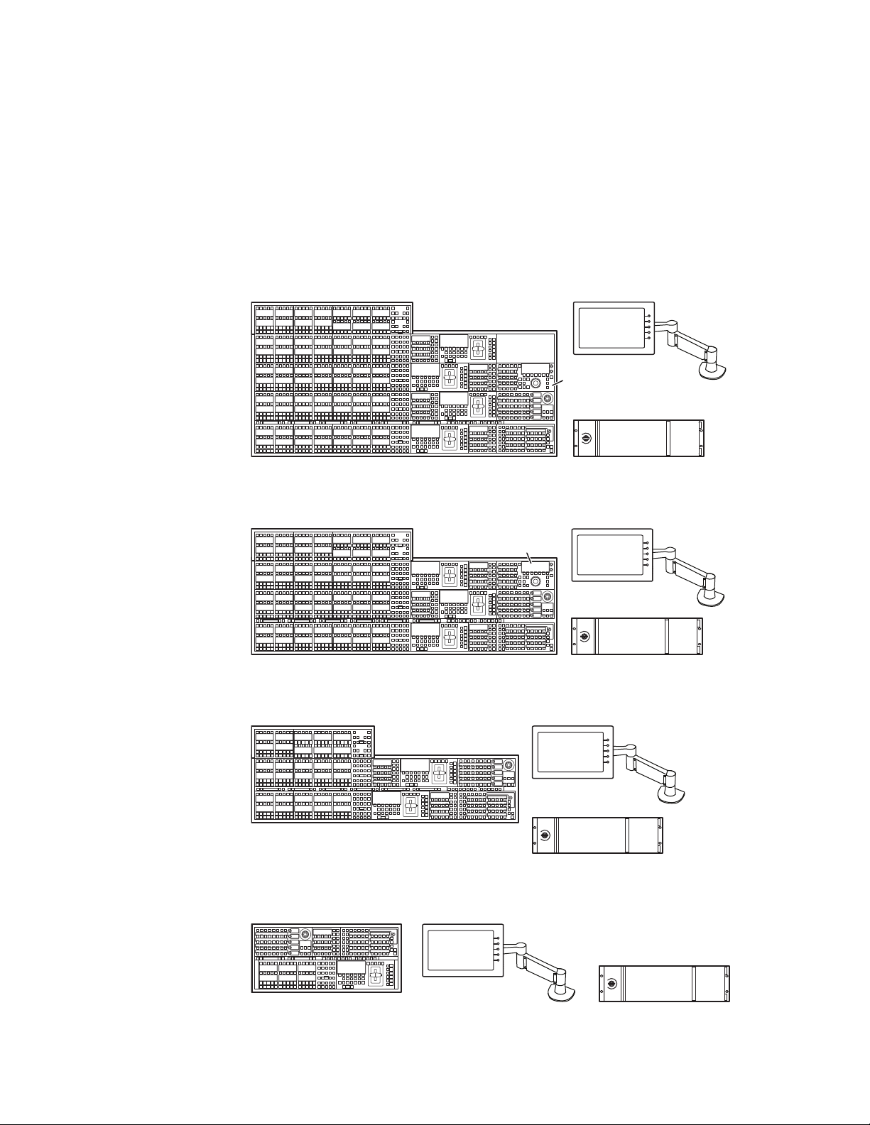
Kayenne Control Surfaces
A Kayenne control surface typically consists of a Control Panel, a Menu
Panel with an included articulated support arm, a Panel Control Unit
(PCU) frame, and optional Satellite Panels. This control surface has an
innovative modular design. Representative Kayenne control surfaces are
shown in the following illustrations.
Figure 2. Kayenne 4-ME 35 Control Surface
Figure 3. Kayenne 3-ME 35 Control Surface
Figure 4. Kayenne 2-ME 25 Control Surface
Figure 5. Kayenne 1-ME 15 Control Surface
10 KAYENNE — Installation Planning Guide
Page 11
The modular design and use of a separate PCU supports the hot-replace-
Flat Control Panel AssemblyCurved Control Panel Assembly
ment of individual Control Panel components, if necessary, while the rest
of the system remains operational.
Multiple Suites and Control Surfaces
A Kayenne system can be subdivided into two suites, if desired, each of
which can have two control surfaces. Hardware resources in the Video Pro
cessor Frame can be assigned to an individual suite during configuration,
essentially creating two separate switchers from one Kayenne system. A
Kayenne PCU can support two control surfaces using its eight available
ports.
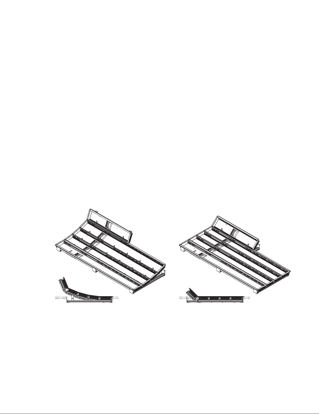
Flat or Curved Control Panel Orientation
The main Kayenne Control Panel supports different physical orientations.
Besides a conventional flat surface, a special support design permits a
curved working surface, where the MEs progressively tilt for improved
ergonomics (
Figure 6).
Kayenne Control Surfaces
-
Figure 6. Curved and Flat Control Surface Installations
KAYENNE — Installation Planning Guide 11
Page 12
Section 1 — Introduction
Hold
Hold
A
Hold
BU1U2
Hold
Far
Key
Split
Rules
Hold
EMEM
Sec
Aux
Pri
Key
3
Key
1
Macro
Key
5
Key
4
Key
2
RtrKeKey
6
EMEM
Macroro
Rev
Rwd
Run
Tr
ans
Rate
Auto
Run
Pa
nel
Mem
Menu
Mix
Transns
PVW
Tr
ans
Rate
EMEM
Runun
Ptntn
Limit
Pst
BLK
Key
1
Key
2
Key
3
Key
4
Key
5
Key
6
Key1
Cut
Key2
Cut
Key4
Cut
Key3
Cut
Key6
Cut
Key5
Cut
Key1
Auto
Key2
Auto
Key3
Auto
Key4
Auto
Key6
Auto
Cut
Auto
Key5
Auto
Userer5Userer
6
Userer4W
ipe2W
ipe
1
Userer3Userer2Userer
1
Key
Prior
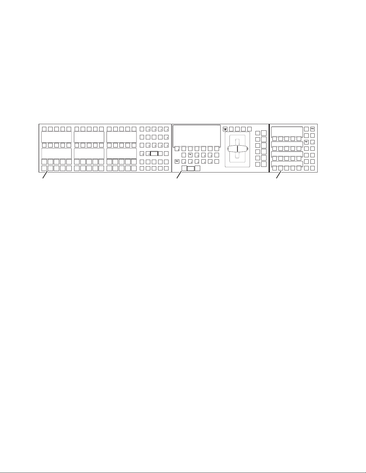
Control Panel Stripes
The main Kayenne Control Panel is organized into from one to five Stripes.
Each Stripe consists of a tray and its complement of drop-in modules. An
ME Stripe has a module for Source Selection, Transition, and individual
E-MEM control (Figure 7). Additional Master E-MEM, Machine Control,
Multi-Function, and Local Aux modules are populated to complete the
control surface functionality.
Figure 7. Portion of Control Panel ME Stripe
Key
Key
Hold
Key
Spl
Hold
Hold
Hold
Source Module (35, 25, or 15) Local E-MEM ModuleTransition Module
Key
Macro
Far
Key
Key
Rules
Sec
Hold
Key
EMEM
Key
ipe
ipe
Cut
ans
EMEM
Lim
Key
Key
Key
Key
Auto
Ke
Ke
Auto
Cut
Ke
Ke
Auto
Cut
Ke
Ke
Auto
Cut
Ke
Ke
Auto
Cut
Ke
Ke
Auto
Cut
Ke
Ke
Auto
Cut
EMEM
ans
nel
Rate
Mem
Me
Ma
Run
Rev
Rwd
Run
8623266_54
Control Panel Modules
The following Kayenne modules are available:
• KAYN-PNL-TRM - Transition Module
• KAYN-PNL-LEM - Local E-MEM Module
• KAYN-PNL-MEM - Master E-MEM Module
• KAYN-PNL-MFM - Multi-Function Module
• KAYN-PNL-SRC-35, 25, 15 - Source Module, available in 35, 25, and 15
button widths.
Note 15 button widths are only available with 1-ME Control Panels.
• KAYN-PNL-AUX-35, 25 - Local Aux Module, available in 35 and 25
button widths.
• KAYN-PNL-BAR-35, 15 - System Bar, available in two sizes to match
various Control Panel widths.
• KAYN-PNL-DCM - Device Control Module, available as an option for
3 and 4-ME panels and as a satellite panel module.
12 KAYENNE — Installation Planning Guide
Page 13
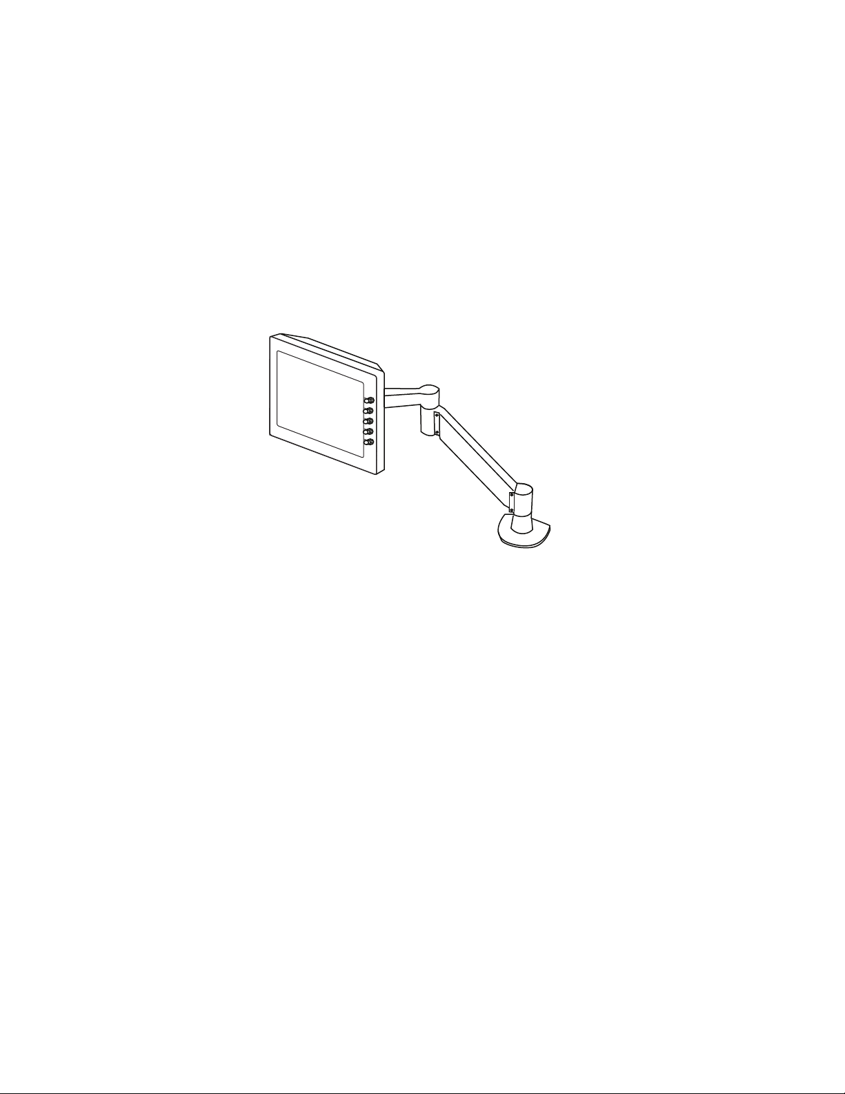
Touch Screen Menu Panel and PC Menu Control
Each Kayenne control surface includes a Menu Panel that features a wide
format 15 in. touch screen display. An articulated arm is also included,
offering a wide variety of installation options (Figure 8). The Menu Panel
has a standard VESA-75 hole pattern and M4 threads, compatible with this
and many other mounting devices.
The Menu Panel has four USB ports, two on the right side edge of the panel
and two on the back for keyboard and mouse (wired or wireless are sup
ported).
Figure 8. Menu Panel with Articulated Arm
Kayenne Control Surfaces
-
8623266_05
An additional touch screen Kayenne Menu Panel is available as an option
(additional Menu Controller Board is required in the PCU).
It is also possible to run the Kayenne Menu application on a standard PC,
permitting mouse and keyboard control from a laptop, or remote control
from any location on the network.
Panel Control Unit
The Kayenne Control Panel and Menu Panel(s) are powered from a separate rack mount Panel Control Unit (PCU). Control surface processing and
communications are handled by this unit. The PCU eliminates the need for
cooling fans in the Control Panel and Menu Panels, making for quiet
system operation.
KAYENNE — Installation Planning Guide 13
Page 14

Section 1 — Introduction
Redundant Power Supplies
Optional built-in redundant power supplies are available for the Kayenne
4-RU and 8-RU Frames. An additional redundant power supply is stan
dard with the Kayenne PCU.
Supported Control Protocols
All Kayenne systems support the following control interfaces and types of
external devices:
• Serial control of VTR/DDR (BVW, AMP, and Odetics protocols),
• Ethernet control of DDR channels (AMP protocol),
• Peripheral Bus II protocol,
• Tally (Contact Closure and Serial),
• GPI Inputs and Outputs,
-
• Routing Control Systems (Jupiter, Encore, SMS-7000, and third party
routers), and
• Grass Valley Editor protocol.
14 KAYENNE — Installation Planning Guide
Page 15

Section 2
Kayenne Control Surfaces
Overview
A typical Kayenne control surface has a modular Control Panel, a Menu
Panel, and is driven by a Panel Control Unit (PCU) frame. Additional Menu
Panels and Satellite Panels are available as options.
A Control Panel consists of system operation modules, which mount into
trays, which are in turn held in place by a Control Panel support structure.
One Control Panel tray filled with modules is called a Stripe. Various
numbers and types of modules and trays can be combined to create a wide
variety of control surface functionality.
The Control Panel and Menu Panel’s processing electronics are located in
the PCU. The Stripes and Menu Panels are connected to the PCU via multipin cables that carry power and communication signals.
Kayenne Control Panels ship to the customer as boxed Stripes, which are
assembled with the support structure on site. You will need to know what
Control Panel configuration(s) you intend to use at your facility in order to
plan your installation effectively.
The Kayenne Control Panel support kit uses 30mm series components
sourced from Bosch Rexroth.
Control Panel Assembly
Support Structure Assembly Required
CAUTION Assembly of the Control Panel support structure is nontrivial. Do not attempt
assembly without first reading the detailed instructions in the separate
Kayenne Installation & Service Manual.
If you purchased commissioning with your Kayenne system, assembly of
the Control Panel support is included as part of the commissioning.
KAYENNE — Installation Planning Guide 15
Page 16

Section 2 — Kayenne Control Surfaces
If you did not purchase commissioning, but would like to reconsider the
option, contact Grass Valley Customer Support.
Control Panel Variations
Seven basic Control Panel assemblies are considered standard: 4-ME 35,
4-ME 25, 3-ME 35, 3-ME 25, 2-ME 35, 2-ME 25, and 1-ME 15. Each assembly
name identifies the number of MEs present and the number of source
selector buttons in each ME.
Two Control Panel Assembly orientations are possible, flat and curved. The
curved panel provides improved operator ergonomics. This orientation
raises the Control Panel height, so visibility of a monitor wall should be
considered prior to installation. An assembled Control Panel can be oper
ated from a tabletop, or it can be installed into a cutout.
The Local Aux Stripe can be connected to the Control Panel support structure at a 45 degree angle, or it can be mounted separately in its own backsplash cutout.
-
The following diagrams show some standard Control Panel assemblies. It
is also possible to create different Control Panel assemblies (for example, a
2-ME 35), since the parts are interchangeable. Specific information for nonstandard configurations is not included in this document.
Control Panel Cooling
The Kayenne Control Panel is externally powered and does not have
internal cooling fans. Electronics in the panel are convection cooled and
require free air movement. Do not install the panel into a sealed space.
CAUTION If the panel is mounted in a counter-top, do not enclose the
lower portion of the cutout. Leave the bottom open to allow
passive air movement.
Truck and High Vibration Environment Considerations
The Kayenne Control Panel has several bolt and screw tightened components. In high vibration environments these attachments could loosen over
time. Loctite Blue 242 or equivalent thread locking compound is recom
mended for these environments. This compound is designed to lock
threaded components together during assembly, but permits them to be
loosened if necessary later using hand tools.
-
During Control Panel assembly, apply a drop of the locking compound to
the ends of the threads of the support beam bolts, to the screws connecting
the cutout lip brackets to the support beams, and to the bolts attaching the
16 KAYENNE — Installation Planning Guide
Page 17
trays to the support beams. Make sure the locking compound is present
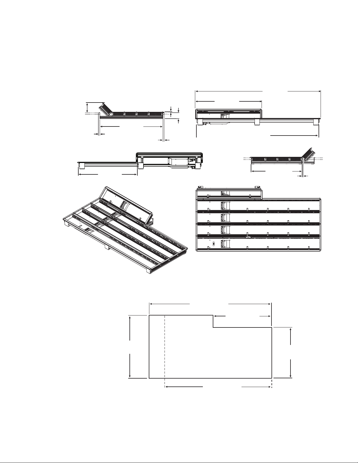
1533.7 mm
60.4 in.
8623266_12
813.5 mm
32.0 in.
1501.5 mm
59.1 in.
622.8 mm
24.5 in.
109.2 mm
4.3 in. 14.3 mm
0.6 in.
275.0 mm
10.8 in.
10.3 mm
0.4 in.
74.0 mm
2.9 in.
where the thread interfaces to each bolt or beam.
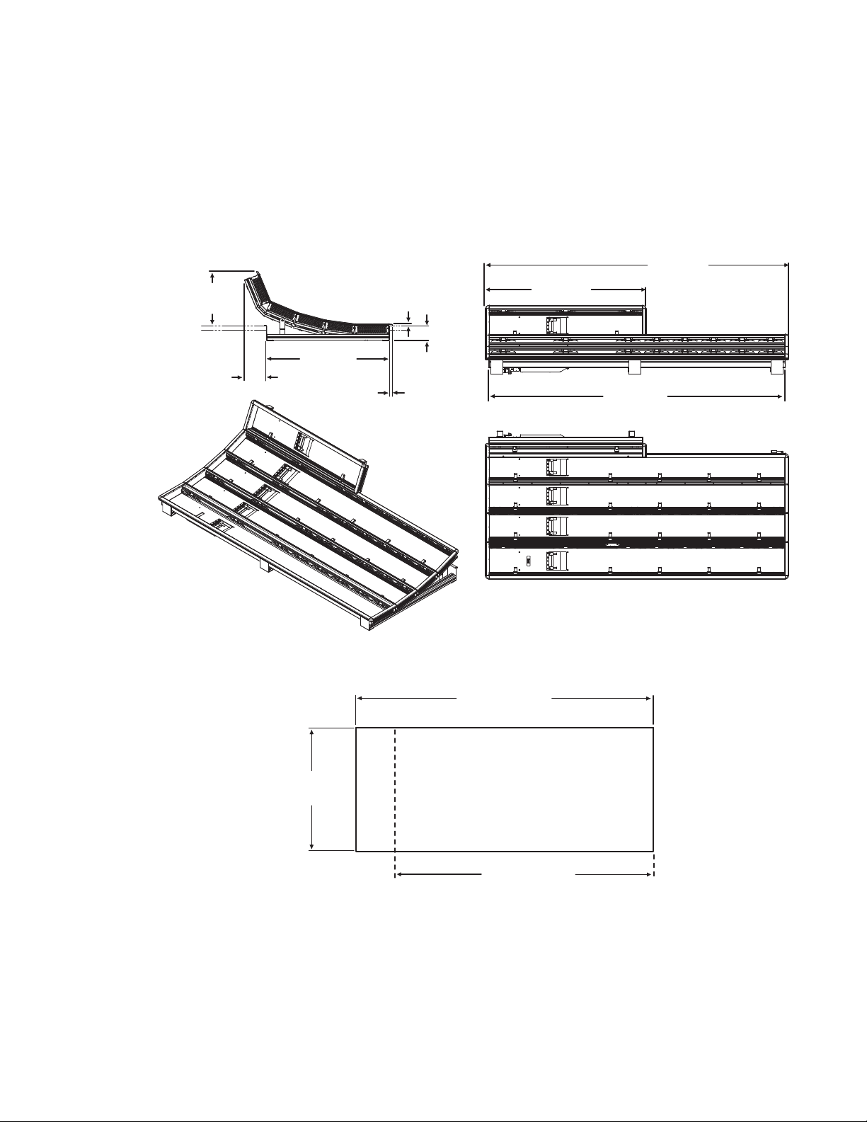
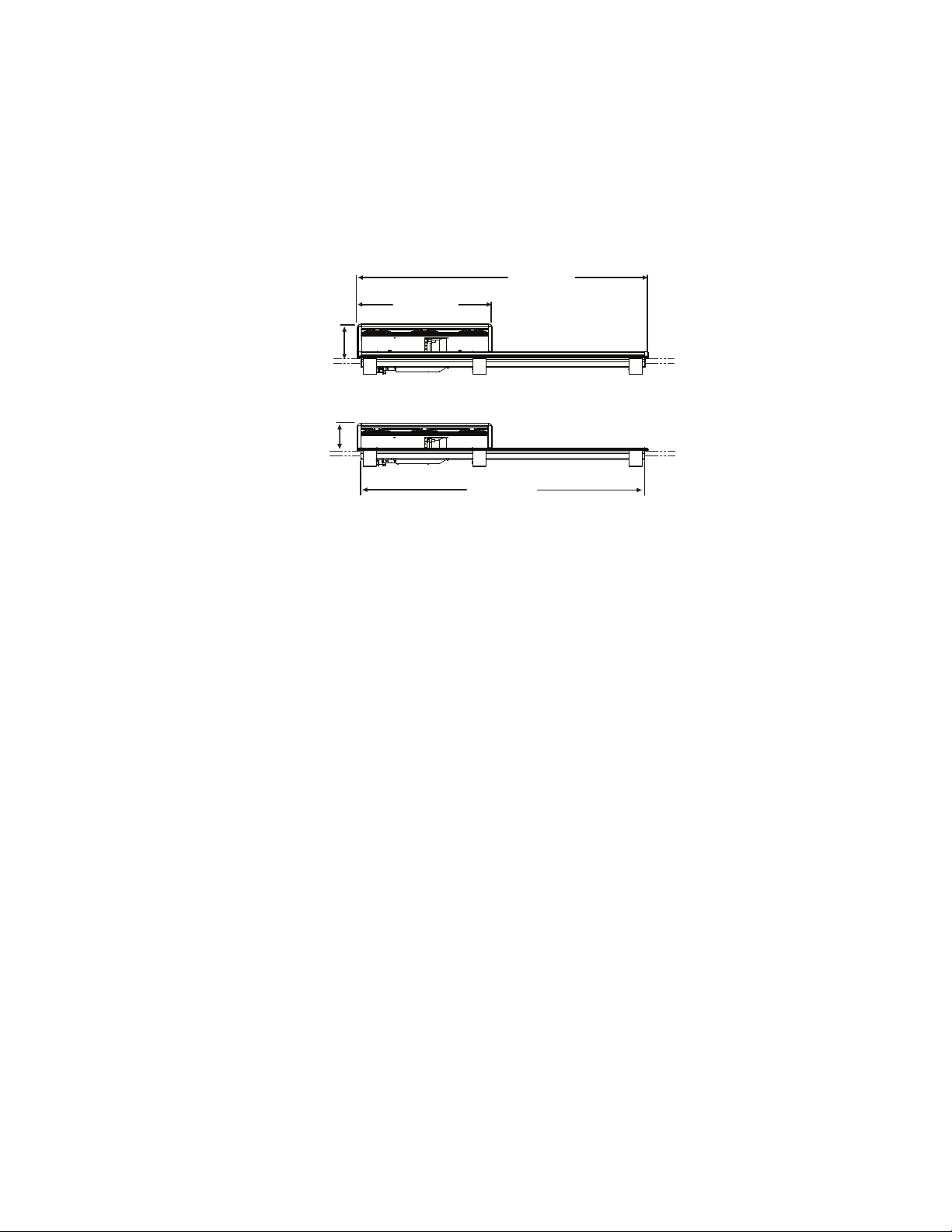
4-ME 35 Control Panel, Curved Assembly
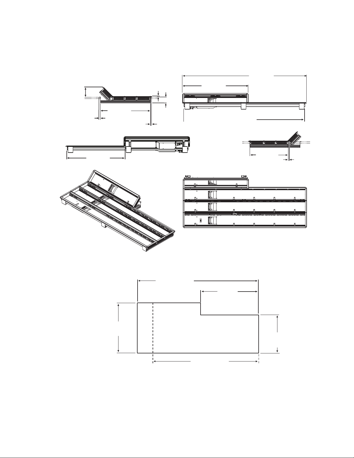
Figure 9. 4-ME 35 Control Panel Dimensions, Curved Installation
Control Panel Assembly
Figure 10. 4-ME Control Panel Cutout Dimensions, Curved Installation
4-ME 35 Panel Cutout
1503.5 +/-1 mm
59.2 +/-.04 in.
1311.5 +/-1 mm
51.6 +/-.04 in.
4-ME 25 Panel Cutout
625 +/-1 mm
24.6 +/-.04 i
n.
4-ME Panel Curved Install Cutout
8623266_14
KAYENNE — Installation Planning Guide 17
Page 18
Section 2 — Kayenne Control Surfaces
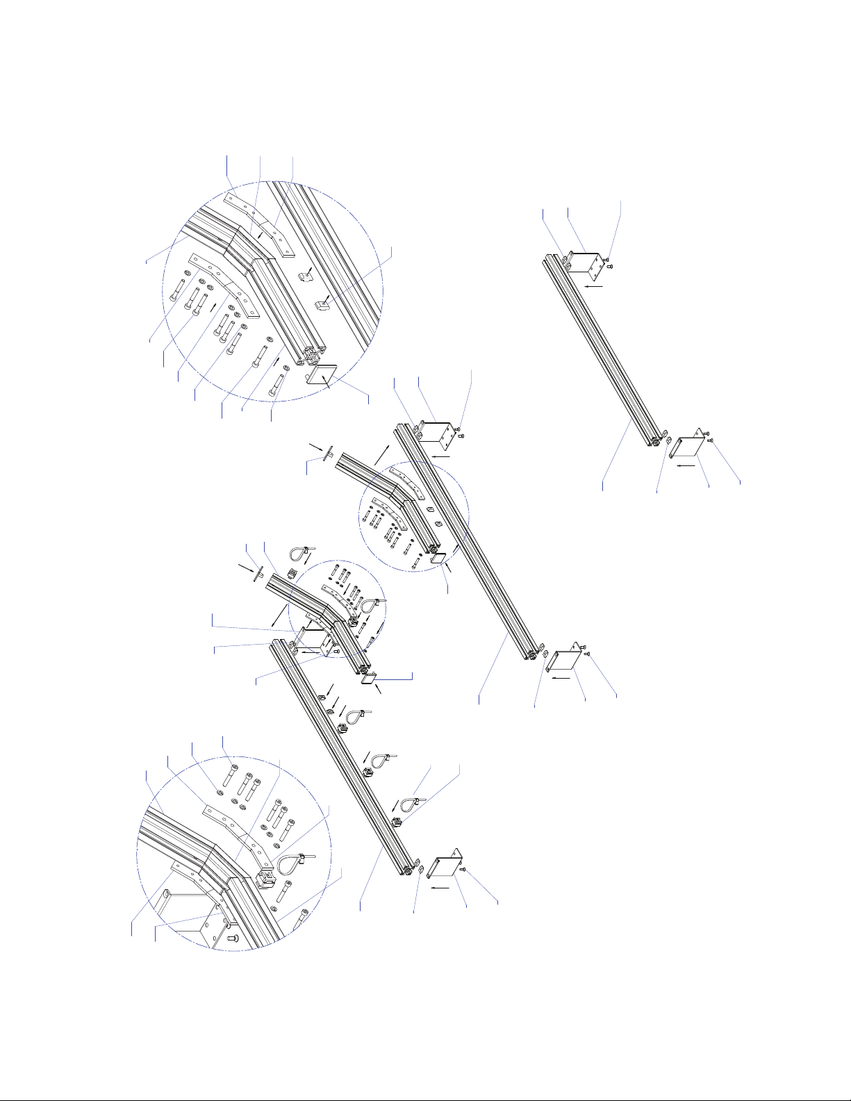
855 7 2700
855 7 2700
855 7 2700
8557 27 80
8557 2780
8557 27 80
8557 2 710
8557 27 10
8557 27 10
855 7 2710
8557 2 710
8557 2710
8557 27 10
855 7 2710
8557 27 10
8557 2710
855 7 2710
8620 3 170
862 0 3170
8620 31 70
855 7 2890
855 7 2890
855 7 2890
8557 28 90
855 7 2890
855 7 2890
B
DETAIL B
A
DETAIL A
8557 2830
8557 28 30
8557 2820
8557 2 820
855 7 2720
850 0 4420
6x
862 0 3200
6x
850 0 442 0
4x
855 7 2810
855 7 2860
862 0 3180
862 0 3180
850 0 7620
850 0 7620
862 0 3180
4x
8500 6460
4x
8620 3180
4x
8500 6460
4x
8620 3 180
4x
8500 6460
4x
850 0 6460
2x
850 0 6460
2x
850 0 6460
2x
862 0 3180
2x
862 0 3180
2x
855 7 2860
8620 3180
862 0 3180
8500 7620
850 0 7620
C
DETAIL C
8500 4 420
862 0 3200
862 0 3200
8500 44 20
8620 3180
862 0 3180
8620 3200
850 0 4420
862 0 3200
850 0 442 0
862 0 3180
2x
855 7 2810
855 7 2800
8500 4420
4x
862 0 3200
4x
862 0 3200
4x
855 7 2800
8622 5420
5x
862 2 5410
5x
8623266_13_r2
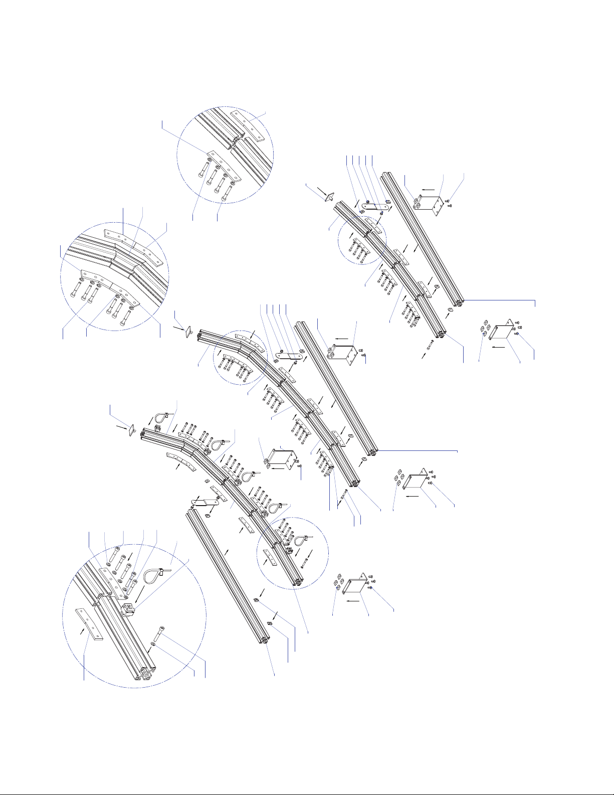
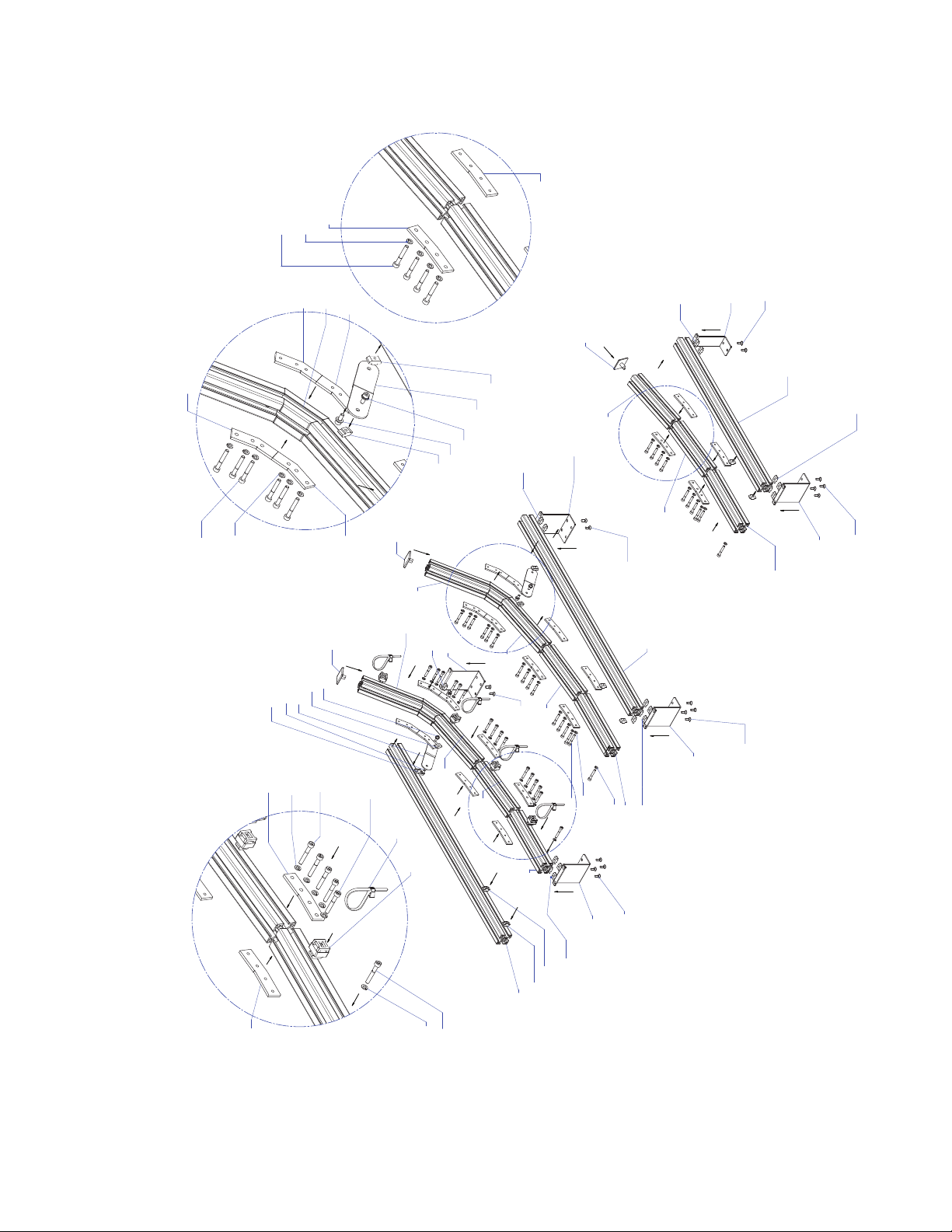
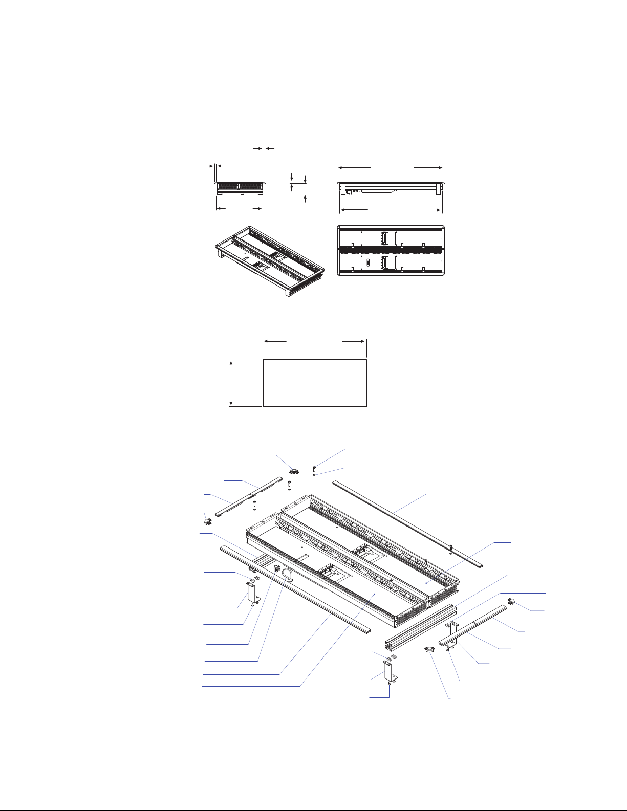
Figure 11. 4-ME Support Structure, Curved Installation
18 KAYENNE — Installation Planning Guide
Page 19
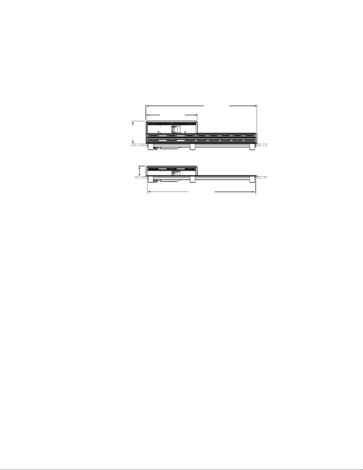
4-ME 35 Control Panel, Flat Assembly
1501.5 mm
59.1 in.
622.8 mm
24.5 in.
1533.7 mm
60.4 in.
813.5 mm
32.0 in.
771.5 mm
30.4 in.
10.4 mm
0.4 in.
14.1 mm
0.6 in.
124.0 mm
4.9 in.
10.3 mm
0.4 in.
74.0 mm
2.9 in.
720.0 mm
28.3 in.
14.3 mm
0.6 in.
8623266_17
Note Read through the entire procedure before you begin actual assembly.
Figure 12. 4-ME 35 Control Panel Dimensions, Flat Installation
Control Panel Assembly
Figure 13. 4-ME Control Panel Cutout Dimensions, Flat Installation
773.5 +/-1 mm
30.5 +/-.04 in.
4-ME 35 Panel Cutout
4-ME Panel Flat Install Cutout
1503.5 +/-1 mm
59.2 +/-.04 in.
28.3 in. +0-.04 in.
1311.5 +/-1 mm
51.6 +/-.04 in.
4-ME 25 Panel Cutout
720 +0-1 mm
625 +/-1 mm
24.6 +/-.04 in.
8623266_16
KAYENNE — Installation Planning Guide 19
Page 20
Section 2 — Kayenne Control Surfaces
8557 2780
8557 2710
8557 2710
8557 2890
8557 2890
8620 3180
2x
8500 6460
2x
8622 5410
5x
8622 5420
5x
855 7 2890
8620 3180
2x
8500 6460
2x
8557 2890
862 0 3180
2x
8500 6460
2x
855 7 2790
8557 2790
855 7 2890
862 0 3180
2x
8500 6460
2x
8557 2890
862 0 3180
2x
850 0 6460
2x
A
DE T A IL A
855 7 2720
8557 2830
855 7 2830
855 7 2820
8557 2820
8500 4420
6x
862 0 3200
6x
8620 3200
2x
850 0 442 0
2x
862 0 3180
2x
8620 3170
862 0 3180
2x
850 0 6460
2x
8620 3170
862 0 3170
862 0 3170
862 0 3170
855 7 2710
B
DETAIL B
855 7 2710
855 7 2720
8557 2710
855 7 2830
855 7 2830
855 7 2820
855 7 2820
862 0 3200
6x
8500 4420
6x
Figure 14. 4-ME Support Structure, Flat Installation
20 KAYENNE — Installation Planning Guide
Page 21
4-ME 25 Control Panel
Control panels with 25 source selection buttons are narrower in width, but
otherwise have the same dimensions as 35 source button models.
Figure 15. 4-ME 25 Control Panel Dimensions
275.0 mm
10.8 in.
124.0 mm
4.9 in.
4-ME 25 Curved Installation
1341.7 mm
621.5 mm
24.5 in.
4-ME 25 Flat Installation
1309.5 mm
52.8 in.
51.6 in.
Control Panel Assembly
8623266_32
KAYENNE — Installation Planning Guide 21
Page 22
Section 2 — Kayenne Control Surfaces
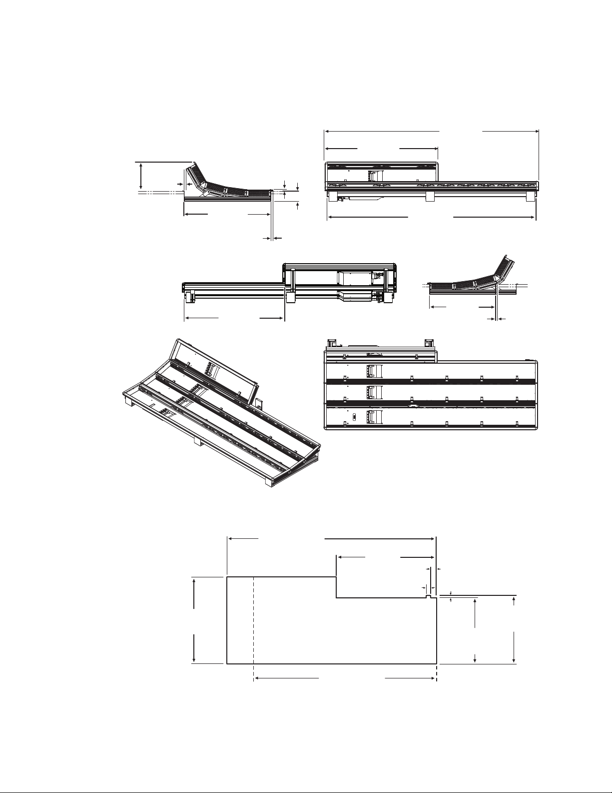
8623266_19
1533.7 mm
60.4 in.
813.5 mm
32.0 in.
1501.5 mm
59.1 in.
622.8 mm
24.5 in.
14.8 mm
0.6 in.
14.3 mm
0.6 in.
208.0 mm
8.2 in.
10.3 mm
0.4 in.
74.0 mm
2.9 in.
720.0 mm
28.3 in.
474.1 mm
18.7 in.
13.9 mm
0.5 in.
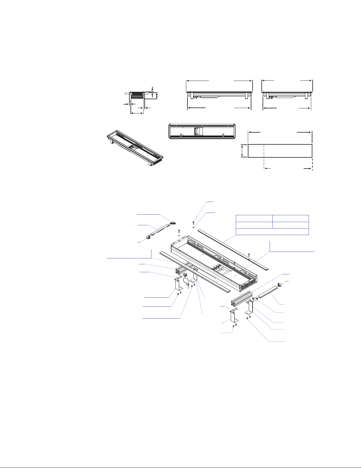
3-ME 35 Control Panel, Curved Assembly
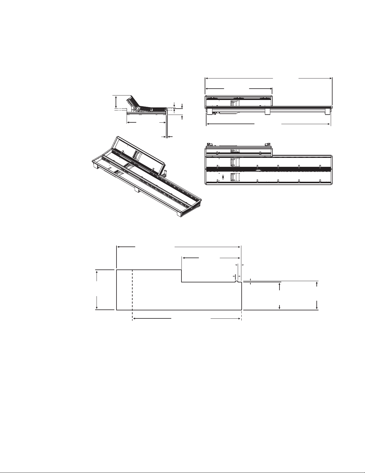
Figure 16. 3-ME 35 Control Panel Dimensions, Curved Installation
Figure 17. 3-ME Control Panel Cutout Dimensions, Curved Installation
3-ME 35 Panel Cutout
625.0 +/-1 mm
24.6 +/-.04 in.
1503.5 +/-1 mm
59.2 +/-.04 in.
3-ME Panel Curved Install Cutout
720 mm
28.3 in.
32.0 +2 -0 mm
1.3 +.08 in. -0 in.
1311.5 +/- 1 mm
51.6 +/- .04 in.
3-ME 25 Panel Cutout
42.5 +/-1 mm
1.7 +/-.04
15 mm
.60 in.
476.0 +/-1 mm
18.7 +/-.04 in.
491.0 +/-1 mm
19.3 +/-.04 in.
8623266_19_r1
22 KAYENNE — Installation Planning Guide
Page 23
Control Panel Assembly
855 7 2700
855 7 2700
8557 2700
8557 2780
8557 2710
8557 2 710
8557 2710
8557 27 10
8557 2710
8557 27 10
8557 2710
855 7 2710
862 0 3170
8620 3 170
8620 3170
855 7 2890
8557 2890
855 7 2890
855 7 2850
8557 2890
8557 28 90
B
DETAIL B
A
DETAIL A
8557 2830
8557 2830
8557 2 820
855 7 2820
855 7 2720
850 0 442 0
6x
8620 3200
6x
8620 31 80
4x
8500 6 460
4x
862 0 3180
4x
8620 31 80
4x
8500 6460
4x
850 0 6460
2x
8500 6460
2x
850 0 6460
2x
8620 3180
2x
862 0 3180
2x
C
DE T AIL C
8500 4420
8620 3200
862 0 3200
8620 31 80
8620 3 180
850 0 442 0
8620 3200
8500 4420
8620 3 180
2x
855 7 2810
8557 2800
8500 4420
4x
862 0 3200
4x
8622 54 20
4x
862 2 5410
4x
8557 2770
850 0 442 0
8x
8620 32 00
8x
8557 28 00
855 7 2810
85 57 27 80
8620 3180
850 0 7620
8557 28 60
8500 76 20
862 0 3180
862 0 3180
4x
8620 31 80
8500 76 20
855 7 2860
862 0 3180
8500 7620
8623266_20_r2
Figure 18. 3-ME Support Structure, Curved Installation
KAYENNE — Installation Planning Guide 23
Page 24
Section 2 — Kayenne Control Surfaces
3-ME Panel Flat Install Cutout
476.0 +/-1 mm
18.7 +/-.04 in.
3-ME 35 Panel Cutout
1503.5 +/-1 mm
59.2 +/-.04 in.
1311.5 +/- 1 mm
51.6 +/- .04 in.
3-ME 25 Panel Cutout
720 mm
28.3 in.
625.0 +/-1 mm
24.6 +/-.04 in.
3-ME 35 Control Panel, Flat Assembly
Figure 19. 3-ME 35 Control Panel Dimensions, Flat Installation
124.0 mm
4.9 in.
10.3 mm
0.4 in.
813.5 mm
32.0 in.
1533.7 mm
60.4 in.
10.2 mm
0.4 in.
720.0 mm
622.8 mm
24.5 in.
14.4 mm
0.6 in.
28.3 in.
Figure 20. 3-ME Control Panel Cutout Dimensions, Flat Installation
74.0 mm
2.9 in.
1501.5 mm
59.1 in.
474.1 mm
18.7 in.
13.9 mm
0.55 in.
8623266_55
24 KAYENNE — Installation Planning Guide
Page 25

Figure 21. 3-ME Support Structure, Flat Installation
855 7 2770
8557 2710
8557 2 710
8557 28 90
8557 2890
862 0 3180
2x
8500 64 60
2x
862 2 5410
4x
8622 5420
4x
855 7 2890
8620 3180
2x
8500 6 460
2x
8557 28 90
862 0 3180
2x
8500 6 460
2x
855 7 2780
8557 2 780
855 7 2890
862 0 3180
2x
850 0 6460
2x
8557 28 90
8620 3 180
2x
850 0 6460
2x
A
DETAIL A
8557 2720
855 7 2830
8557 2830
855 7 2820
8557 2820
850 0 442 0
6x
862 0 3200
6x
862 0 3200
2x
862 0 3180
2x
850 0 6460
2x
8620 3170
8620 3170
862 0 3170
8620 3 170
8557 2 710
B
DETAIL B
855 7 2710
8557 2720
8557 27 10
8557 28 30
855 7 2830
8557 2820
8
557 2820
862 0 3200
6x
8500 4420
6x
8623266_57_r2
Control Panel Assembly
KAYENNE — Installation Planning Guide 25
Page 26

Section 2 — Kayenne Control Surfaces
1341.7 mm
52.8 in.
621.5 mm
24.5 in.
3-ME 25 Flat Installation
1309.5 mm
51.6 in.
124.0 mm
4.9 in.
208.0 mm
8.2 in.
3-ME 25 Curved Installation
3-ME 25 Control Panel
Control panels with 25 source selection buttons are narrower in width, but
otherwise have the same dimensions as 35 source button models.
Figure 22. 4-ME 25 Control Panel Dimensions
26 KAYENNE — Installation Planning Guide
Page 27
2-ME 35 Control Panel, Curved Assembly
8623266_24
1533.7 mm
60.4 in.
813.5 mm
32.0 in.
1501.5 mm
59.1 in.
474.1 mm
18.7in.
14.3 mm
0.6 in.
158.0 mm
6.2 in.
10.3 mm
0.4 in.
74.0 mm
2.9 in.
2-ME Panel Curved Install Cutout
330.5 +/-1 mm
13.0 +/-.04 in.
340.5 +/-1 mm
13.4 +/-.04 in.
32.0 +2 -0 mm
1.3 +.08 in. -0 in.
42.5 +/-1 mm
1.7 +/-.04
2-ME 35 Panel Cutout
1503.5 +/-1 mm
59.2 +/-.04 in.
1311.5 +/- 1 mm
51.6 +/- .04 in.
2-ME 25 Panel Cutout
720 mm
28.3 in.
476.0 +/-1 mm
18.7 +/-.04 in.
10 mm
.40 in.
Figure 23. 2-ME 35 Control Panel Dimensions, Curved Installation
Control Panel Assembly
Figure 24. 2-ME Control Panel Cutout Dimensions, Curved Installation
KAYENNE — Installation Planning Guide 27
Page 28

Section 2 — Kayenne Control Surfaces
A
DETAIL A
B
DETAIL B
C
DETAIL C
855 7 2710
862 0 3170
8557 2890
855 7 2850
8500 6460
4x
850 0 6460
2x
862 0 3180
2x
8557 27 60
8620 3 180
4x
8620 32 00
2x
850 0 442 0
2x
8620 3180
2x
8557 2700
850 0 442 0
8x
862 0 3200
8x
8557 28 00
8557 2810
8557 2 890
855 7 2850
8620 3 180
4x
850 0 6460
4x
8500 6 460
2x
8620 3 180
2x
855 7 2770
8620 32 00
2x
8500 4420
2x
8620 3180
2x
8557 2700
855 7 2830
8557 2830
855 7 2820
855 7 2820
8557 2720
850 0 442 0
6x
862 0 3200
6x
8620 3180
850 0 7620
8557 2 860
8500 7620
8620 3180
8557 2 700
8557 27 80
855 7 2710
855 7 2710
8557 2720
8620 31 70
862 0 3170
8557 2 890
8620 3 180
4x
8620 3 180
8620 3 180
8620 3180
4x
8620 3 170
8622 5420
3x
8622 5410
3x
8500 7620
8557 28 60
8500 76 20
862 0 3180
8620 3180
Figure 25. 2-ME Support Structure, Curved Installation
28 KAYENNE — Installation Planning Guide
Page 29

2-ME 35 Control Panel, Flat Assembly with Local Aux
8623266_58
1533.6 mm
60.4 in.
813.5 mm
32.0 in.
1501.5 mm
59.1 in.
474.1 mm
18.7in.
14.3 mm
0.6 in.
124.0 mm
4.9 in.
10.3 mm
0.4 in.
74.0 mm
2.9 in.
10 mm
0.4 in.
2-ME Panel Flat Install Cutout
327.5 +/-1 mm
12.9 +/-.04 in.
2-ME 35 Panel Cutout
1503.5 +/-1 mm
59.2 +/-.04 in.
1311.5 +/- 1 mm
51.6 +/- .04 in.
2-ME 25 Panel Cutout
720 mm
28.3 in.
476.5 +/-1 mm
18.8 +/-.04 in.
Figure 26. 2-ME 35 Control Panel Dimensions, Flat Installation
Control Panel Assembly
Figure 27. 2-ME Control Panel Cutout Dimensions, Flat Installation
KAYENNE — Installation Planning Guide 29
Page 30

Section 2 — Kayenne Control Surfaces
Figure 28. 2-ME Support Structure, Flat Installation
855 7 2830
855 7 2830
DE T AIL B
8557 27 70
862 0 3180
2x
855 7 2850
8557 27 10
855 7 2710
8500 6460
2x
8557 2 820
855 7 2720
8557 28 20
850 0 442 0
6x
8620 3 200
6x
B
8620 3 180
2x
855 7 2850
862 0 3170
855 7 2710
8620 3 170
8500 4420
8620 3 200
2x
8620 3 200
855 7 2820
6x
6x
8557 2820
8620 31 80
2x
855 7 2890
8557 2720
855 7 2710
8557 2830
DETAIL A
8500 64 60
2x
8622 5410
4x
8622 54 20
4x
8620 3180
2x
8557 2850
850 0 6460
2x
862 0 3170
A
855 7 2770
855 7 2760
862 0 3180
2x
8557 2850
850 0 6460
8500 6460
2x
8620 3 180
2x
850 0 6460
2x
855 7 2850
2x
8623266_60_r2
30 KAYENNE — Installation Planning Guide
Page 31
2-ME 35 Control Panel, Flat without Local Aux
8623266_21
1501.5 mm
59.1 in.
1533.7 mm
60.4 in.
325.4 mm
12.8 in.
10.3 mm
0.4 in.
74.0 mm
2.9 in.
15.2 mm
0.60 in.
15.8 mm
0.62 in.
8557 28 50
862 2 5420
2x
862 2 5410
2x
8557 2850
8557 2760
8620 3180
2x
862 0 3180
2x
8500 64 60
2x
8500 64 60
2x
72850
8557 2850
8557 2760
8620 3180
2x
850 0 6460
2x
8620 3180
2x
850 0 6460
2x
8623266_23_r1
855
8557 2 850
8620 3 180
2x
8500 6 460
2x
8557 28 50
855 7 2760
862 0 3180
2x
850 0 6460
2x
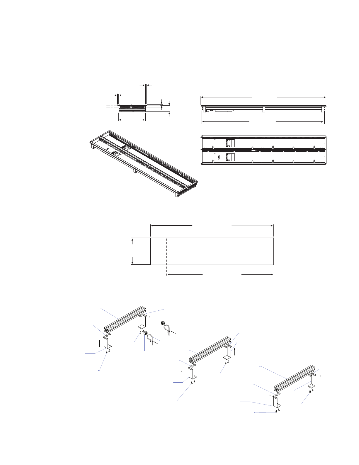
Figure 29. 2-ME 35 Control Panel Dimensions, Flat Installation
Control Panel Assembly
Figure 30. 2-ME Control Panel Cutout Dimensions, Flat Installation
2-ME 35 Panel Cutout
1503.5 +/-1 mm
59.2 +/-.04 in.
327.5 +/-1 mm
12.9 +/-.04 in.
2-ME Panel Flat Install Cutout
(Local Aux Installed Separately)
1311.5 +/-1 mm
51.6 +/-.04 in.
2-ME 25 Panel Cutout
8623266_22
Figure 31. 2-ME Support Structure, Flat Installation, w/o Local Aux Stripe
KAYENNE — Installation Planning Guide 31
Page 32
Section 2 — Kayenne Control Surfaces
1341.7 mm
52.8 in.
621.5 mm
24.5 in.
2-ME 25 Flat Installation
1309.5 mm
51.6 in.
124.0 mm
4.9 in.
158.0 mm
6.2 in.
2-ME 25 Curved Installation
2-ME 25 Control Panel
Control panels with 25 source selection buttons are narrower in width, but
otherwise have the same dimensions as 35 source button models.
Figure 32. 2-ME 25 Control Panel Dimensions
32 KAYENNE — Installation Planning Guide
Page 33
1-ME 15 Control Panel
327.5 +/-1 mm
12.9 +/-.04 in.
8623266_28
728 +/-1 mm
28.7 +/-.04 in.
1-ME 15 Panel Cutout
850 0 4960
6x
850 0 4420
6x
855 7 1480
855 7 1480
855 7 1480
855 7 3180
855 7 3180
850 06460
4x
850 06460
2x
850 06460
2x
862 0 3180
4x
862 0 3180
2x
862 0 3180
2x
8557 2 850
855 7 2850
855 7 2850
2x
855 7 2760
8557 2 760
855 7 3190
855 7 3190
855 7 1480
855 7 2550
855 7 2630
8557 3 150
w/ Silkscreen Kayenne Logo
855 7 3120
862 2 5420
2x
8622 5 410
2x
Figure 33. 1-ME 15 Control Panel Dimensions, Flat Installation
15.8 mm
0.62 in.
15.2 mm
0.60 in.
10.3 mm
0.4 in.
Control Panel Assembly
758.3 mm
29.9 in.
325.4 mm
12.8 in.
74.0 mm
2.9 in.
726.0 mm
28.6 in.
8623266_27
Figure 34. 1-ME 15 Control Panel Cutout Dimensions, Flat Installation
Figure 35. 1-ME Support Structure and Trim, Flat Installation
KAYENNE — Installation Planning Guide 33
Page 34
Section 2 — Kayenne Control Surfaces
Separately Mounted Local Aux Stripe (35 & 25 Models)
Figure 36. Local Aux Stripe Separate Installation Dimensions
15.2 mm
0.60 in.
154.7 mm
8623266_30
Figure 37. Local Aux Stripe Support Structure, Tray, and Trim
855 7 1480
855 7 3180
855 7 1480
855 7 3060 - 3 5 A UX B UT TON
855 7 3070 - 2 5 A UX B UT TON
855 7 2710
862 0 3180
6.1 in.
2x
10.3 mm
0.4 in.
15.8 mm
0.62 in.
74.0 mm
2.9 in.
Local Aux 35 Width
813.7 mm
32.0 in.
781.5 mm
30.8 in.
156.5 +/-1 mm
6.2+/-.04 in.
850 0 4960
4x
850 0 4420
4x
Local Aux 25 Width
621.7 mm
24.5 in.
589.5 mm
23.2 in.
Local Aux 35 Panel Cutout
783.5 +/-1 mm
30.8 +/-.04 in.
Aux Panel
Installed Separately
591.5 +/-1 mm
23.3 +/-.04 in.
Local Aux 25 Panel Cutout
35 AUX BUTT ON 25 AUX BUTT ON
855 7 3000
Silkscreen Kayenne Logo
855 7 3010
HOUSING CPL. AUX
855 7 258 0 - 35 A UX B UTT ON
855 7 259 0 - 25 A UX B UTT ON
855 7 2710
855 7 1480
855 7 2850
850 06460
2x
850 06460
2x
862 0 3180
2x
862 0 3180
2x
855 7 2850
855 7 2850
850 06460
2x
855 7 3180
855 7 1480
862 0 3180
2x
855 7 2850
850 06460
2x
8623266_31_r2
Control Panel Stripe-PCU Connections
Connectors on the outside bottom of the Stripe connect to the PCU, using a
special multi-pin cable that carries both power and communications.
CAUTION Do not connect or disconnect the multi-pin cables linking a Kayenne Control
Panel tray and PCU while the PCU is powered up. Damage to the Kayenne
equipment can result.
34 KAYENNE — Installation Planning Guide
Page 35
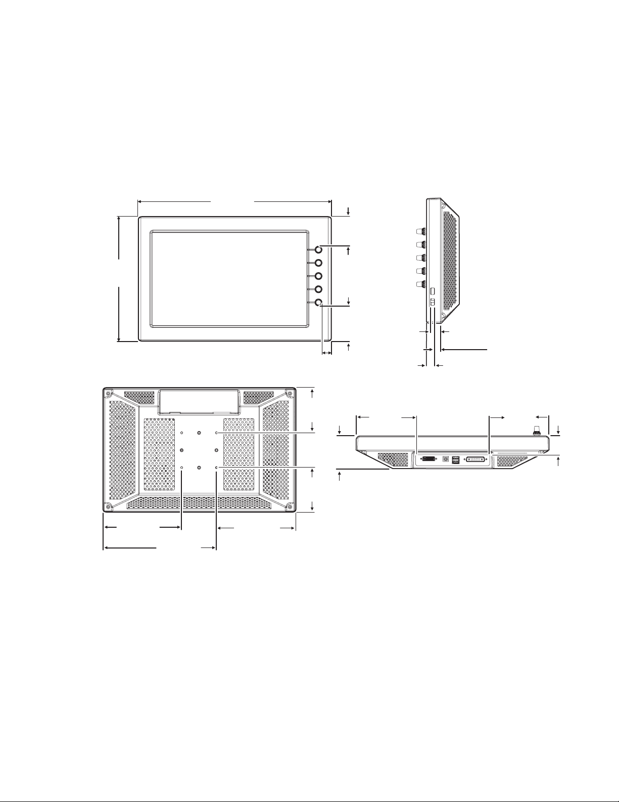
Touch Screen Menu Panel Installation
Front View
Rear View
Side View, Right
8623266_07
Bottom View
170.9 mm
6.73 in.
245.9 mm
9.68 in.
171.9 mm
6.77 in.
19.1 mm
.79 in.
76.2 mm
3.00 in.
417.8 mm
16.45 in.
270.0 mm
10.63 in.
64.1 mm
2.52 in.
129.4 mm
5.09 in.
8.4 mm
.33 in.
17.3 mm
.68 in.
12.7 mm
5.0 in.
97.5 mm
3.84 in.
97.5 mm
3.84 in.
128.4 mm
5.06 in.
70.6 mm
2.78 in.
40.6 mm
1.60 in.
Menu Panel Dimensions
Figure 38. Menu Panel Dimensions
Touch Screen Menu Panel Installation
Menu Panel Connectors
The Kayenne Menu Panel’s processor is located in the PCU. The Menu
Panel connects to the PCU with a special multi-pin cable that carries both
power and communications signals.
CAUTION Do not connect or disconnect the multi-pin cables linking a Kayenne Menu
Panel to the PCU while the PCU is powered up. Damage to the Kayenne equipment can result.
KAYENNE — Installation Planning Guide 35
Page 36

Section 2 — Kayenne Control Surfaces
Side View, Right
8623266_11
Bottom View
USB (2)
USB (2)
DVI-D USB Type B
Optional use with PC
PCU Connector
Figure 39. Menu Panel Connections
Menu Panel Cooling
CAUTION Do not install the Menu Panel into an enclosed space. Passive
air movement is required for cooling.
The Kayenne Menu Panel is externally powered and does not have internal
cooling fans. The electronics are convection cooled through perforations in
the rear of the Menu Panel chassis. Mounting the panel free-standing with
the articulated arm allows maximum air movement, and is the preferred
installation method. If an alternative method is used, ensure that all vents
are unobstructed and adequate airflow is available.
Menu Panel Articulated Arm Installation
The Kayenne Menu Panel has VESA 75 threads on the back that can be used
to mount the Menu Panel to the supplied articulated arm, or any VESA
compliant mounting system.
36 KAYENNE — Installation Planning Guide
Page 37

Touch Screen Menu Panel Installation
157 mm
6.18 in.
225.5 mm
8.88 in.
Max
vertical
range
454.7 mm
17.0 in.
Max
horizontal
range
685.8 mm
27.0 in.
114.3 mm
4.5 in.
438.2 mm
17.25 in.
387.4 mm
15.25 in.
195.3 mm
7.69 in.
79.4 mm
3.125 in.
S IDE VIEW
Vertical Range
TOP VIEW
Horizontal Range
TOP VIEW
Arm Folded
Figure 40. Articulated Arm Range of Motion Dimensions
The supplied articulated arm is equipped with a flex-mount system, permitting a variety of mounting options (table-top, wall mount, etc.). See the
documentation provided with the articulated arm for specific installation
instructions.
Additional Kayenne Menu Panels
Touch Screen Menu Panel Using PCU
An additional Touch Screen Menu Panel, available as an option, requires a
second Menu Panel processor board in the PCU. A multi-pin cable is pro
vided with the option to supply power and signals to the Menu Panel.
Touch Screen Menu Panel Using PC
A Touch Screen Menu Panel can be configured to operate without a PCU,
using a PC. Communication between the Menu Panel and the Kayenne
system is handled using the PC’s Ethernet connection. A special power
supply brick is required, which powers the Menu Panel through the PCU
connector.
-
KAYENNE — Installation Planning Guide 37
Page 38

Section 2 — Kayenne Control Surfaces
Menu Application on PC (Keyboard & Mouse)
The Kayenne menu application can also be run on a standard PC, permitting mouse and keyboard control from a nearby laptop, or remote control
of the Kayenne system from any location on the network. If a PC is used for
Kayenne Menu operation, the PC’s IP address must be set to a compatible
value to work with the rest of the Kayenne system.
38 KAYENNE — Installation Planning Guide
Page 39

Kayenne Frames
General Rack Mounting Instructions
Weight Distribution
Make sure that you mount the unit in the rack so that it is evenly balanced
to prevent damage to the frame and to avoid creating a hazardous condi
tion. Kayenne Frames (8-RU, 4-RU, and PCU) require rear rack support.
Section 3
-
Cooling Requirements
The maximum ambient temperature for a Kayenne chassis is 40-degrees C
(104-degrees F) monitored at the air intake. Installing the frame in a closed
or multi-unit rack assembly together with other units could increase the
maximum ambient temperature for this unit. If the unit is installed in a
rack, ventilation openings should not be blocked or otherwise covered.
Make sure you install the frame to allow for cooling airflow.
Power Connections
When connecting the unit to the supply circuit be sure that the supply
circuit of the rack is not overloaded. The unit must be well-grounded. The
safety ground is accomplished via the third wire in the AC line cord(s). The
rear panel ground lug is available for an optional ground.
All Kayenne Frame power supplies are 100V-240V AC +/-10% autorange,
power factor corrected. Each power supply has its own line IEC line cord.
Connecting each line cord to a separate AC circuit is recommended.
KAYENNE — Installation Planning Guide 39
Page 40

Section 3 — Kayenne Frames
Kayenne 8-RU Video Processor Frame Installation
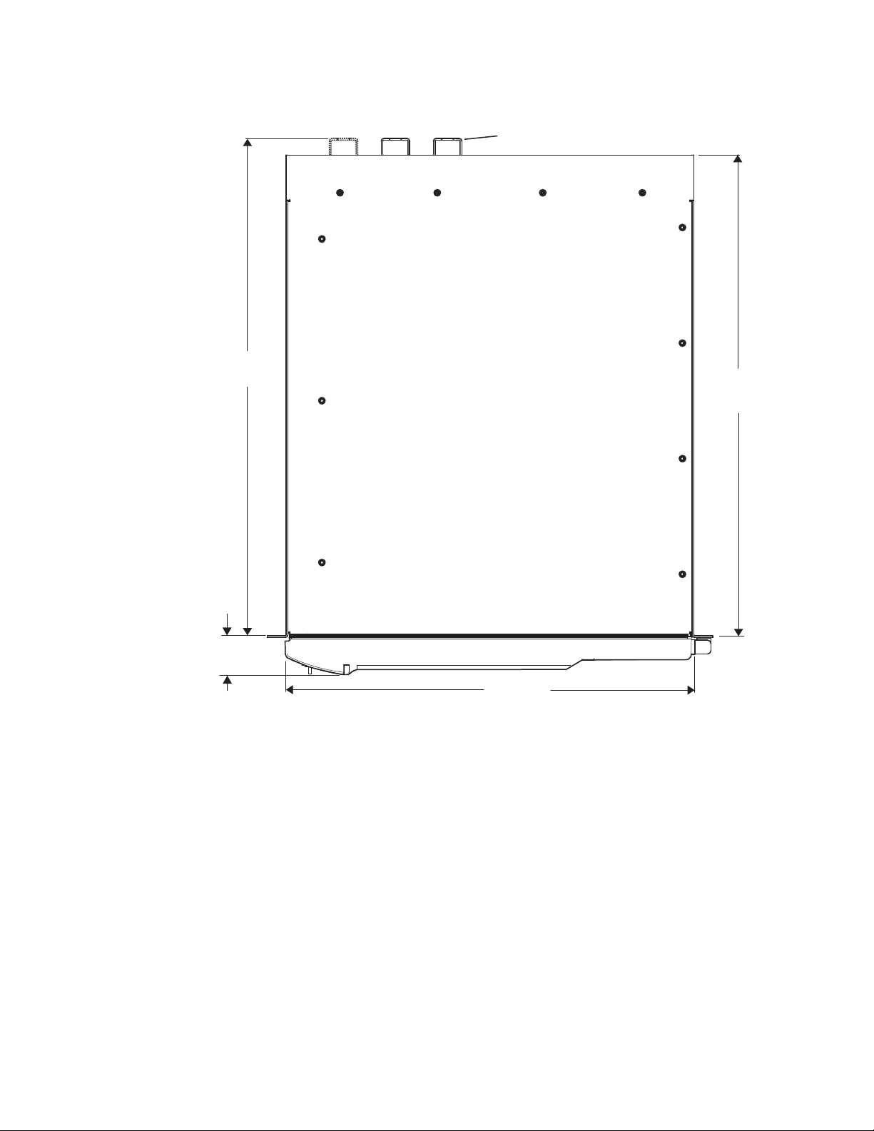
8-RU Frame Dimensions
Figure 41. Kayenne 8-RU Frame Dimensions (Front View)
483 mm
465 mm
18.31 in.
166 mm
6.5 in.
19.0 in.
178 mm
7.0 in.
355 mm
13.97 in.
8623266_93
40 KAYENNE — Installation Planning Guide
Page 41
Kayenne 8-RU Video Processor Frame Installation
523 mm
20.58 in.
541 mm
21.29 in.
AC Line Cord Retainers
(3 on 8-RU, 2 on 4-RU)
442 mm
17.4 in.
39.6 mm
1.56 in.
Figure 42. Kayenne 8-RU and 4-RU Frame Dimensions (Top View)
KAYENNE — Installation Planning Guide 41
Page 42

Section 3 — Kayenne Frames
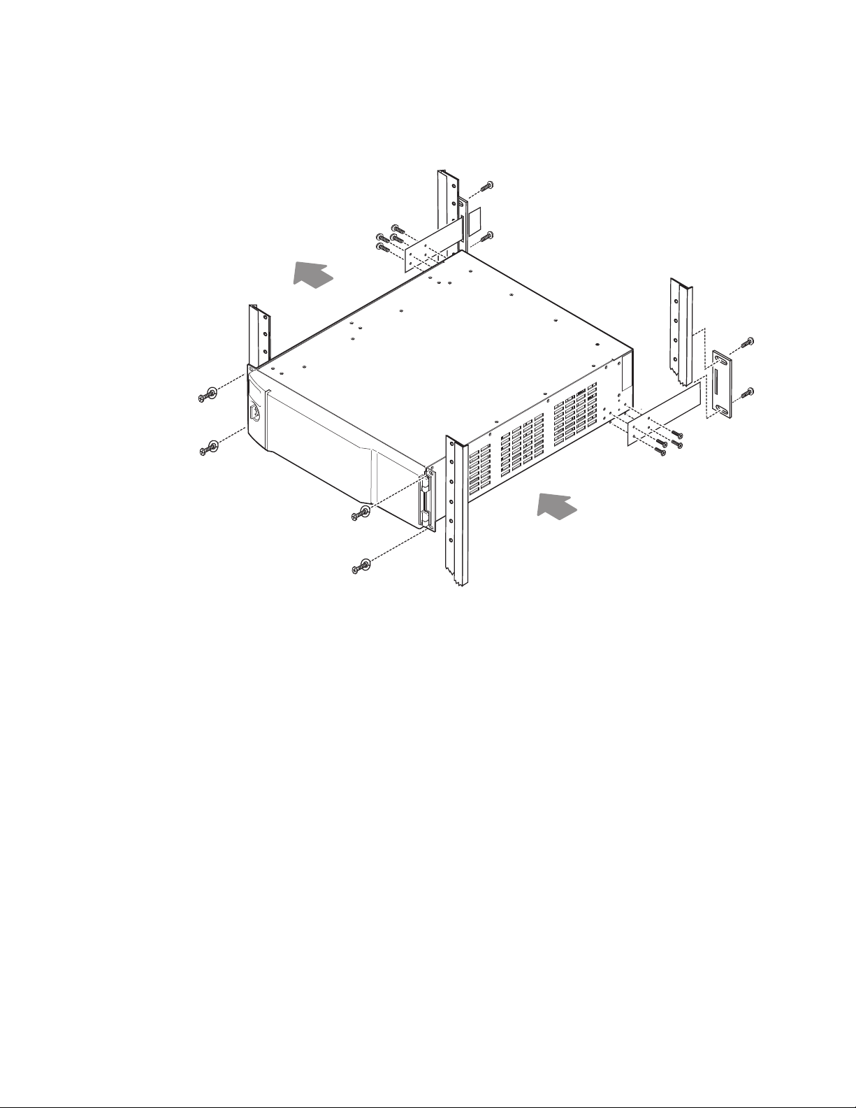
8-RU Frame Rack Mounting
Figure 43. Kayenne 8-RU Frame Rack Mounting and Cooling Airflow
Air
Exhaust
CAUTION Kayenne Frames (8-RU, 4-RU, and PCU) installations require the use of the
provided rear rack supports.
Air intake holes exist on the right side of the frame (as you face the frame
front) and air exhaust holes are on the left. Make sure adequate ventilation
is provided for the Kayenne Frame. Do not block ventilation holes, which
could make the frame overheat.
Door Removal Clearance
CAUTION Mounting a Kayenne Frame in a rack immediately below equipment that
extends forward from the rack may not provide enough clearance to completely remove the Kayenne door.
8623266_53
Air
Intake
Rear Rack
Support
The Kayenne frame door should be able to be completely removed when
installed in a rack immediately below conventional flush mounted rack-ear
only equipment.
42 KAYENNE — Installation Planning Guide
Page 43
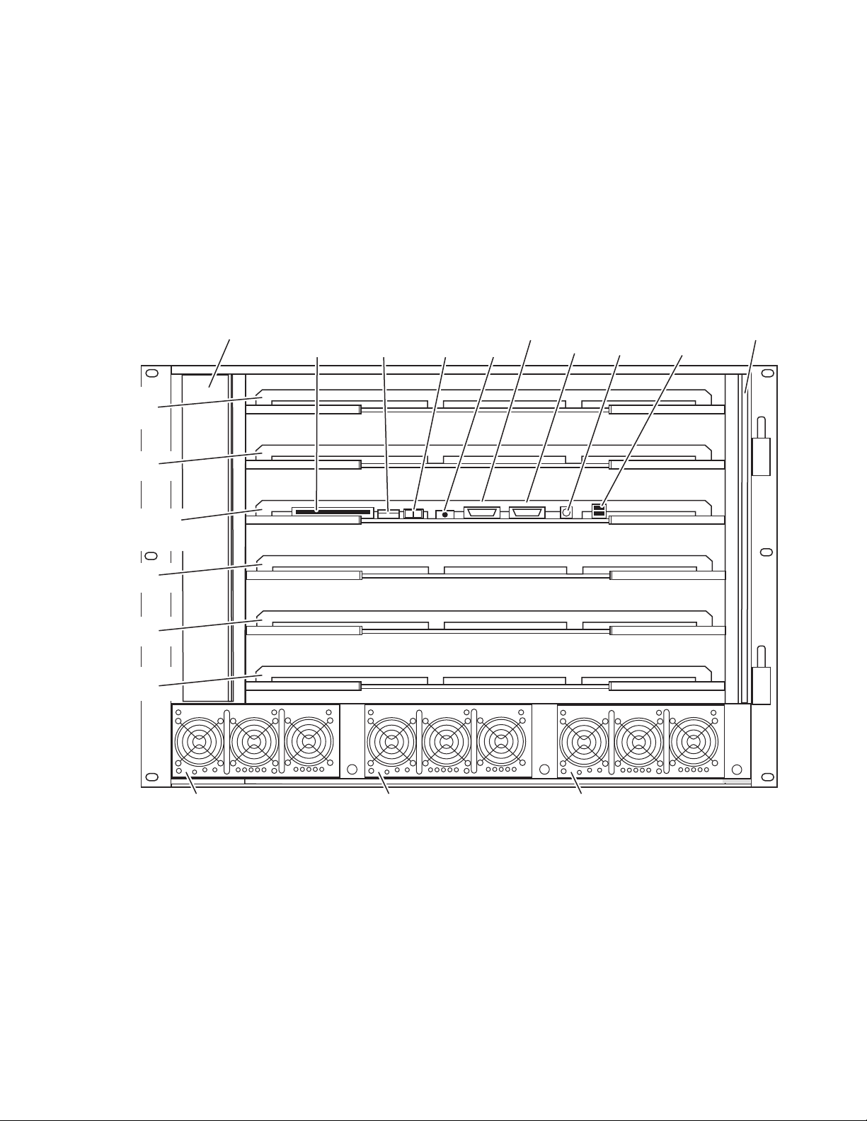
If the chassis is mounted immediately below equipment that extends
ON
OFF
ME A
ME B
ME C
ME D
eDPM
Controller
(and ME 50)
Fan Assembly Flash
Memory
Boot Mode
DIP Switch
Power
Switch
Reset
Button
USB
(not used)
Air Filter
Power Supply Unit 2 Power Supply Unit 3 (option)
RS-232 PS2
Keyboard
VGA
Power Supply Unit 1
8623266_43
forward from the rack (for example, under another Kayenne frame), extra
space must be reserved to be able to remove the front door. The door lifts
off its hinges vertically and for the 8-RU frames 23.7 mm (0.93-in.) of clear
ance is required to completely remove the door. A flush design 1 RU blank
filler panel can be used for clearance, if required.
8-RU Frame Connectors
Figure 44. Kayenne 8-RU Frame, Front View with Door Removed
Kayenne 8-RU Video Processor Frame Installation
-
KAYENNE — Installation Planning Guide 43
Page 44

Section 3 — Kayenne Frames
Video In
1 M/E: 1-24
2 M/E: 1-48
3 M/E: 1-72
4 M/E: 1-96
Figure 45. Kayenne 8-RU Frame, Backplane View
Video Out
1 M/E: 1-12
2 M/E: 1-24
3 M/E: 1-36
4 M/E: 1-48
GPI In/Out 1-8
Tally 1-24
SD Reference In
HD Reference In
Tri Level Sync
GPI In/Out 9-16
Tally 25-48
(2 M/E only)
LAN
(Internal Switch
with 4 Ports)
RS422/485
Serial Ports
(8)
Grounding Lug
(Not used with Kayenne) 100-240V AC
8-RU Frame Power Supplies
The 8-RU Kayenne Video Processor frame has two power supplies standard. A minimum of two supplies are needed for 8-RU frame operation.
An additional power supply is available as an option for redundancy. It
slides into the extra power supply slot in the chassis. When equipped with
the redundant power supply option, the frame will continue to operate
without interruption should a single power supply fail.
Redundant AC
Power Supply 3
(option)
100-240V AC
Power Supply 2
Power Supply 1
GPI In/Out 17-24
Tally 49-72
(3 M/E only)
GPI In/Out 25-32
Tally 73-96
(4 M/E only)
8623266_35
44 KAYENNE — Installation Planning Guide
Page 45

Kayenne 4-RU Video Processor Frame Installation
177 mm
6.97 in.
482 mm
19.0 in.
465 mm
18.31 in.
165 mm
6.5 in.
8623266_51
Kayenne 4-RU Video Processor Frame Installation
4-RU Frame Dimensions
Figure 46. Kayenne 4-RU Frame Dimensions (Front View)
The top view dimensions of the Kayenne 4-RU Frame are the same as the
8-RU Frame, except there are only two AC line cord retainers (see
on page 41).
Figure 42
KAYENNE — Installation Planning Guide 45
Page 46

Section 3 — Kayenne Frames
4-RU Frame Rack Mounting
Figure 47. Kayenne 4-RU Frame Rack Installation and Cooling Airflow
Air
Exhaust
CAUTION Kayenne Frame (8-RU, 4-RU, and PCU) installations require the use of the
provided rear rack supports.
Air intake holes exist on the right side of the frame (as you face the frame
front) and air exhaust holes are on the left. Make sure adequate ventilation
is provided for the Kayenne Frame. Do not block any ventilation holes,
which could make the frame overheat.
Door Removal Clearance
CAUTION Mounting a Kayenne Frame in a rack immediately below equipment that
extends forward from the rack may not provide enough clearance to completely remove the Kayenne door.
8623266_52
Air
Intake
Rear Rack
Support
The Kayenne frame door should be able to be completely removed when
installed in a rack immediately below conventional flush mounted rack-ear
only equipment.
If the chassis is mounted immediately below equipment that extends
forward from the rack (for example, under another Kayenne frame), extra
space must be reserved to be able to remove the front door. The door lifts
46 KAYENNE — Installation Planning Guide
Page 47

off its hinges vertically and for the 4-RU and PCU frames 7.7 mm (0.3 in.)
ON
OFF
Top Slot
ME A
Bottom Slot
ME B
Controller
(and ME 50)
USB
(not used)
Air Filter
Fan Assembly
Flash
Memory
Power
Switch
Reset
Button
RS-232
Power Supply Unit 1 Redundant Power Supply Unit 2 (option)
8623266_44
PS2
Keyboard
VGABoot Mode
DIP Switch
8623266_38
(Not used with Kayenne) 100-240V AC
Power Supply 1
Redundant AC
Power Supply 2
(option)
Grounding Lug
GPI In/Out 9-16
Tally 25-48
(2 M/E only)
GPI In/Out 1-8
Tally 1-24
HD Reference In
Tri Level Sync
Video Out
1 M/E: 1-12
2 M/E: 1-24
Video In
1 M/E: 1-24
2 M/E: 1-48
SD Reference In
LAN
(Internal Switch
with 4 Ports)
RS422/485
Serial Ports
(8)
of clearance is required to completely remove the door. A flush design 1 RU
blank filler panel can be used for clearance, if required.
4-RU Frame Connectors
Figure 48. Kayenne 4-RU Frame, Front View with Door Removed
Kayenne 4-RU Video Processor Frame Installation
Figure 49. Kayenne 4-RU Frame, Backplane View
KAYENNE — Installation Planning Guide 47
Page 48
Section 3 — Kayenne Frames
483 mm
19.0 in.
132.6 mm
5.22 in.
8623266_09
4-RU Frame Power Supplies
The 4-RU Kayenne Video Processor frame has one power supply standard.
An additional power supply is available as an option for redundancy. It
slides into the extra power supply slot in the chassis. When equipped with
the redundant power supply option, the frame will continue to operate
without interruption should a single power supply fail.
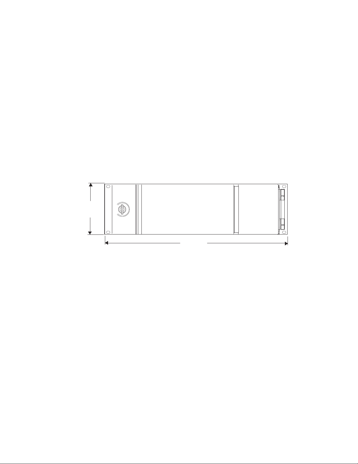
Panel Control Unit (PCU) Installation
PCU Dimensions
Figure 50. Panel Control Unit Dimension (Front View)
48 KAYENNE — Installation Planning Guide
Page 49

18.0 mm
0.71 in.
Panel Control Unit (PCU) Installation
Figure 51. Panel Control Unit Dimensions (Top View)
442.0 mm
17.4 in.
AC Line Cord Retainers
530.9 mm
20.90 in.
39.6 mm
1.56 in.
8623266_10
KAYENNE — Installation Planning Guide 49
Page 50
Section 3 — Kayenne Frames
PCU Frame Rack Mounting
Figure 52. Panel Control Unit Rack Installation and Cooling Airflow
Air
Exhaust
Rear Rack
Support
CAUTION Kayenne Frames (8-RU, 4-RU, and PCU) installations require the use of the
provided rear rack supports.
Air intake holes exist on the right side of the frame (as you face the frame
front) and air exhaust holes on the left. Make sure to provide adequate ven
tilation for the Kayenne Frame. Do not block any ventilation holes, which
can prevent cooling air from reaching the frame and cause it to overheat.
Door Removal Clearance
CAUTION Mounting a Kayenne Frame in a rack immediately below equipment that
extends forward from the rack may not provide enough clearance to completely remove the Kayenne door.
The Kayenne frame door should be able to be completely removed when
installed in a rack immediately below conventional flush mounted rack-ear
only equipment.
8621266_37
Air
Intake
-
If the chassis is mounted immediately below equipment that extends
forward from the rack (for example, under another Kayenne frame), extra
space must be reserved to be able to remove the front door. The door lifts
50 KAYENNE — Installation Planning Guide
Page 51

off its hinges vertically and for the 4-RU and PCU frames 7.7 mm (0.3-in.)
OFF
ON
100-240V AC
Power Supply 1
Redundant AC
Power Supply 2
USB (2)
Chassis
Fan
Panel Processor Menu Processor
Second Menu
Processor (Option)
AT
Keyboard
Compact
Flash
Panel
Reset
Menu
Reset
Status
Display &
Boot Switch
Serial Port
Com 1
VGA
Display
Power
Switch
Status
Display &
Boot Switch
Air
Filter
USB (2)
AT
Keyboard
Serial Port
Com 1
VGA
Display
RS 422/485
AC 1AC 2
PANELS
MENU
GPI
USB
2123456 7 81
USB
(Panel Processor)
GPI
(inactive)
Grounding Lug
LAN
(Internal Switch
with 6 Ports)
Panel
LAN
(Reserved LAN)
Menu
Panel 1
Panel Stripe
Connectors (8)
Menu
Panel 2
RS422/485
Serial Port
(Panel
Processor)
8623266_50
100-240V
AC Power 1
Redundant
AC Power 2
of clearance is required to completely remove the door. A flush design 1 RU
blank filler panel can be used for clearance, if required.
PCU Connectors
Figure 53. Panel Control Unit, Front View with Door Removed
Panel Control Unit (PCU) Installation
Figure 54. Panel Control Unit, Backplane View
CAUTION Do not connect or disconnect the multi-pin cables linking a PCU to a Menu
Panel or Control Panel Stripe while the PCU is powered up. Damage to the
Kayenne equipment can result.
KAYENNE — Installation Planning Guide 51
Page 52

Section 3 — Kayenne Frames
PCU Power Supplies
The Kayenne system uses a Panel Control Unit (PCU). This 3RU rackmount frame powers the Control Panel and Touch Screen Menu Panel(s),
and houses the processors for these devices. The PCU has one processor for
the Control Panel, and another processor for the standard Touch Screen
Menu Panel. An additional Menu Panel processor is available as an option.
The PCU has an internal Ethernet switch, used for Menu Panel processor
communications. Six Ethernet ports are available on the back. Two ports are
used internally for the Menu Panels. An additional Ethernet port is used for
Control Panel processor communications.
The Kayenne PCU frame has two power supplies standard. The frame will
continue to operate without interruption should a single power supply fail.
52 KAYENNE — Installation Planning Guide
Page 53

System Cabling
8623266_39_r2
Technical
Director’s
Laptop
CD-ROM
Drive
Disable Internet or
Wireless Connections
Isolate Kayenne System
from External Network
Ethernet
Serial Control
Custom Multi-Pin (Menu, 15m / 50ft max length)
Custom Multi-Pin (Panel, 15m / 50ft max length)
Maintenance Only (board front edge)
*
Internal
Control
Kayenne Video Processor
Frame
Video
Processor
CPU
Compact
Flash
Image
Store
CPU
RAM
Only
Ehternet Switch
1
2
3
4
5
6
7
8
Panel Main LAN
Panel Aux LAN
(not used)
Ehternet Switch
1
2
3
4
5
6
7
8
Kayenne PCU
Menu
CPU
Hard
Disk
Menu
CPU
(option)
Hard
Disk
Panel
CPU
Compact
Flash
Menu Panel
Kayenne Control Panel
Remote Aux Panel
Local Aux Stripe
ME Stripe
ME Stripe
ME Stripe
(Up to 8 Stripe Connections)
USB
RS-422/485
Facility LAN
Switch
Ethernet
Router
Remote Aux Panel
Clip Store
(Image Store Clips)
USB (2)*
Keyboard, VGA*
RS-232*
RS-422/485 (8)
GPI In/Out
Tally
Keyboard, VGA*
RS-232*
USB (2)*
USB (4)
RS-232*
USB (2)*
Keyboard, VGA*
Overview
The Kayenne system uses Ethernet, serial, and USB connections. Custom
multi-pin cabling is also used to connect the Kayenne Panel Control Unit
(PCU) to Kayenne control surface and Menu Panel components. The
Kayenne Video Processor Frame and PCU each have built-in Ethernet
switches. Tally outputs and GPI I/O (General Purpose Interface Input/
Output) control is also available (
Figure 55. Kayenne System Communications Overview
Section 4
Figure 55).
KAYENNE — Installation Planning Guide 53
CAUTION The facility network used for your Kayenne system (and other video produc-
tion equipment) should be kept separate from any external network, to
prevent network traffic from adversely affecting Kayenne system operation.
Kayenne system power is provided by power supplies built into the
Kayenne Video Processor Frame and Kayenne PCU. Power is routed to
Page 54

Section 4 — System Cabling
8623266_40_r1
Internal
Control
Kayenne Video Processor
Frame
Video
Processor
CPU
Image
Store
CPU
Ehternet Switch
1
2
3
4
5
6
7
8
Panel Main LAN
Panel Aux LAN
(reserved)
Ehternet Switch
1
2
3
4
5
6
7
8
Kayenne PCU
Menu
CPU
Menu
CPU
(option)
Panel
CPU
Two Cable PCU Frame Connection
Network Cabling
Kayenne control surface components and Menu Panels from the PCU
through the custom multi-pin cabling. Additional Frame and PCU power
supplies are available for redundancy.
Serial digital video and key input and output signals are connected to the
Kayenne Video Processor Frame. Specified MatchDef Input pair and
SetDef Output pair connectors on the Frame can be used for internal format
conversion (an optional feature). Separate Video Reference inputs are avail
able for HD and SD formats.
Network connections are required between the Kayenne Video Processor
Frame and the PCU. The PCU routes network communications to and from
the Control Panel Stripes and Menu Panels, using custom multi-pin cables.
The Ethernet switches built into the Kayenne Frame and PCU auto-detect
speed and polarity, and are 10/100/1000 Mbps capable. Either straightthrough or crossover Ethernet cabling can be used. Available Ethernet con
nectors may be connected to the Facility LAN or other devices, as needed.
However, should the Kayenne Frame or PCU power down, the internal
Ethernet switches will also power down, interrupting communication to
devices connected to that Frame’s or PCU’s internal Ethernet switches.
Only connect devices that are Kayenne system related.
-
-
54 KAYENNE — Installation Planning Guide
The use of two Ethernet cables to connect the PCU to the Frame is recommended (Figure 56).
Figure 56. PCU to Frame Network Connection Methods
The PCU Ethernet switch to Frame Ethernet switch cable connection is
used for Menu Panel communications. The second cable connects the Panel
PCU directly to the Frame’s Ethernet switch. Using two cables provides
additional Ethernet communications throughput (to support Image Store
file operations) and also offers redundancy. Because the Menu Panel and
Page 55
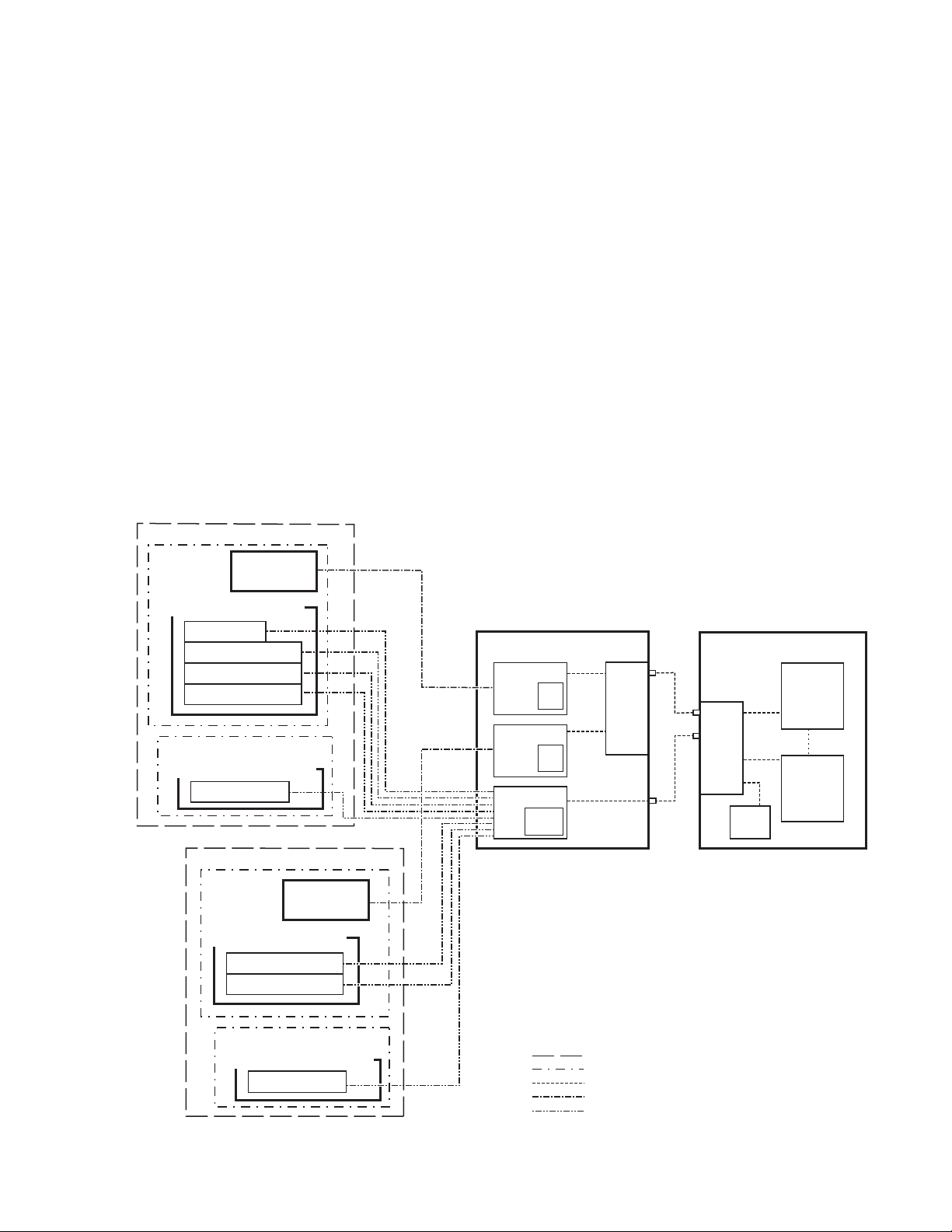
the Control Panel have independent cable connections, failure of one of
8623266_41_r2
Panel Main LAN
Ehternet Switch
1
2
3
4
5
6
7
8
Kayenne PCU
Menu
CPU
Hard
Disk
Menu
CPU
(option)
Hard
Disk
Panel
CPU
Compact
Flash
Menu Panel
Kayenne Control Panel
Local Aux Stripe
ME Stripe
ME Stripe
ME Stripe
Menu Panel
Kayenne Control Panel
ME Stripe
ME Stripe
Kayenne Satellite Panel
Satellite Stripe
Suite Boundary
Control Surface Boundary
Ethernet
Custom Multi-Pin (Menu, 15m / 50ft max length)
Custom Multi-Pin (Panel, 15m / 50ft max length)
Kayenne Satellite Panel
Satellite Stripe
Internal
Control
Kayenne Video Processor
Frame
Video
Processor
CPU
Image
Store
CPU
Ehternet Switch
1
2
3
4
5
6
7
8
Option
Slot
Kayenne Suite 2
Suite 2
Control Surface A
Suite 2
Control Surface B
Kayenne Suite 1
Suite 1
Control Surface A
Suite 1
Control Surface B
(Up to 8 Stripe Connections)
these cables will not completely disable the Kayenne system. Either the
Menu Panel or the Control Panel will remain operational after a single
network cable failure.
Suites and Control Surfaces
A Kayenne system can be divided into two suites. Kayenne system
resources (MEs, eDPMs, external devices, etc.) can be assigned to each
suite, creating two switchers with one Kayenne system. Each suite can be
subdivided into two control surfaces. Each control surface is intended for
use by a single operator. The Kayenne Control Panel system flexibility
permits locating these control surfaces in physically separate locations.
Custom multi-pin cable runs are limited to 15 meters (50 ft.) If this length is
sufficient, a single PCU can be used for an entire multi-suite Kayenne
system (
Figure 57. Two Suites with Two Control Surfaces Using One PCU
Figure 57).
Network Cabling
KAYENNE — Installation Planning Guide 55
Page 56

Section 4 — System Cabling
Using a second PCU, Kayenne suites can be located anywhere on the network, permitting system control from different rooms, floors, or even different buildings (Figure 58).
Figure 58. Two Suites Using Two PCUs
Kayenne Suite 1
Menu Panel
Kayenne Control Panel
Local Aux Stripe
ME Stripe
ME Stripe
ME Stripe
Kayenne Suite 2
Menu Panel
Kayenne Control Panel
Local Aux Stripe
ME Stripe
ME Stripe
ME Stripe
8623266_42_r2
Kayenne PCU 1
Menu
CPU
Menu
CPU
(option)
Panel Main LAN
Panel
CPU
Kayenne PCU 2
Menu
CPU
Menu
CPU
(option)
Panel
CPU
7
1
2
3
4
8
5
Ehternet Switch
6
7
8
Panel Main LAN
Ethernet
(100m / 300ft max single hop length,
unlimited distance using switches)
1
2
3
4
5
Ehternet Switch
6
Kayenne Video Processor
Frame
1
5
2
6
3
7
4
8
Ehternet Switch
Option
Slot
Suite Boundary
Ethernet
Custom Multi-Pin (Menu, 15m / 50ft max length)
Custom Multi-Pin (Panel, 15m / 50ft max length)
Video
Processor
CPU
Internal
Control
Image
Store
CPU
Customer Supplied Ethernet Routers and Switches
Existing facility Ethernet switches can be used in conjunction with a
Kayenne system. If connecting to a network area outside that used by the
Kayenne system, use of an appropriately configured Ethernet Router is
strongly advised. This reduces network traffic on the Kayenne network and
keeps it isolated. Any Ethernet switches added specifically for use with the
56 KAYENNE — Installation Planning Guide
Page 57

Network Cabling
Kayenne system should be 1000 Mbps capable for the most efficient operation (see Tab le 1).
Table 1. Ethernet Specifications
10BaseT, 100BaseT, 1000BaseT compatible.
Typ e
Cables
Connectors
Length
Speed
Ports
Switch
Unmanaged
Managed
Category 5 cable, 8 conductor twisted pair.
The system will work at lower ratings with reduced performance.
1000BaseT components are highly recommended.
RJ-45 male connector at each end of cable.
100BaseT, 1000BaseT: 328 ft. (100 m) maximum.
10BaseT: 984 ft. (300 m) maximum.
Use additional switches to exceed maximum cable runs.
10/100/1000 Mbps
RJ-45 auto-negotiating 10/100/1000 Mbps; number of ports required
is dependent upon system size. Frame and PCU ports are capable of
1000 Mbps. Using a 1000 Mbps Ethernet switch enhances Image Store
transfer speeds.
Recommended. Configuration not required, but does not provide
remote monitoring capability.
May be used. Requires configuration, but offers remote monitoring
capability.
KAYENNE — Installation Planning Guide 57
Page 58

Section 4 — System Cabling
Factory Default Network Settings
Table 2. Kayenne System Default IP Addresses
Device IP Address
Video Processor Frame CPU 192.168.0.170
Image Store CPU 192.168.0.171
Control Panel Surface 1A 192.168.0.173
Touch Screen Menu Panel 1 192.168.0.175
Touch Screen Menu Panel 2 192.168.0.176
Control Panel Surface 1B 192.168.0.177
Control Panel Surface 2A 192.168.0.178
Control Panel Surface 2B 192.168.0.179
IP Address: 192.168.1.2
Frame IP: 192.168.1.1
32-Crosspoint Remote Aux Panels
V1.6.5 and higher software:
(hard reset with the front panel buttons)
All Subnet Masks) 255.255.255.0
All Gateways
(except V1.6.5 software Remote Aux panel)
Reserved For Future Use
Video Processor Frame Gigabit Ethernet
PCU Panel Reserved LAN Port
Gateway IP: 192.168.1.1
Subnet Mask 255.255.255.0
Note
192.168.0.1
CAUTION
192.168.0.172
192.168.0.174
32-Crosspoint Remote Aux Panel default settings must
be changed to operate with a Kayenne system whose
other components are configured with their default IP
addresses.
Do not connect any devices configured with the following IP addresses to a Kayenne network.
To integrate Kayenne devices into an existing network, ask the local
network administrator for that network’s subnet mask. Before changing IP
addresses always set the subnet masks of the Kayenne devices to the mask
of the local network.
Control Surface Cabling
Connectors on the outside bottom of the Control Panel tray connect to
numbered ports on the PCU, using special multi-pin cables that carry both
power and communications signals. Special cables are also used to connect
the Menu Panels to the PCU.
CAUTION Do not connect or disconnect the multi-pin cables linking a Kayenne Control
Panel tray or Menu Panel to the PCU while the PCU is powered up. Damage
to the Kayenne equipment can result.
58 KAYENNE — Installation Planning Guide
Page 59
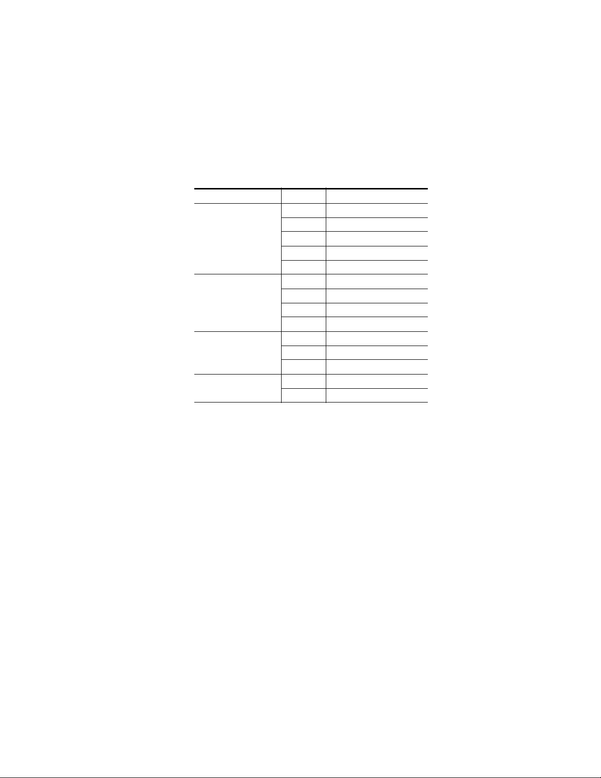
ME and Local Aux Stripe Connections
It is recommended that the PCU numbered ports be connected to Control
Panel Stripes in ascending ME order, followed by the Local Aux Stripe.
PCU port connections can be re-mapped, but this order matches the default
configuration. The table below shows the connections for various Kayenne
Control Panel models used in a single suite.
Table 3. PCU Port to Control Panel Stripe Connections, Single Suite
Control Panel Model PCU Port Panel Stripe
1 ME 1 (top Stripe)
2 ME 2 (second Stripe)
4-ME with Local Aux
3-ME with Local Aux
2-ME with Local Aux
1-ME (no Local Aux)
3 ME 3 (third Stripe)
4 ME 4 (bottom Stripe)
5 Local Aux Stripe
1 ME 1 (top Stripe)
2 ME 2 (second Stripe)
3 ME 3 (bottom Stripe)
4 Local Aux Stripe
1 ME 1 (top Stripe)
2 ME 2 (bottom Stripe)
3 Local Aux Stripe
2 Master EMEM, MFM (top tray)
1 ME (bottom tray)
Control Surface Cabling
Satellite Panel Cabling
PCU Cabling
CAUTION Do not connect or disconnect multi-pin PCU cables while the PCU is powered
up. Damage to the Kayenne equipment can result.
Each Satellite Panel has a standard multi-pin cable for connection to the
PCU. Modules independent of a particular Stripe (for example Device
Control or Master E-MEM modules) can use any available PCU connector.
Modules to be associated with a particular Stripe (like a Transition Module)
must be connected to the next higher PCU port for that Stripe. For example,
if you wish to use a Transition Module with ME 4 that uses PCU Port 4,
plug the Satellite Panel into PCU Port 5, and move the Local Aux Stripe
connector (if used) to PCU Port 6.
KAYENNE — Installation Planning Guide 59
Page 60

Section 4 — System Cabling
Internal Cabling
Touch Screen Menu Panels (Used with PCU)
CAUTION The RJ-45 connectors inside the Satellite Panel trays are used for proprietary
communications only. Ethernet devices may be damaged if plugged into
these connectors.
The Single Module Satellite Panel has internal module cabling the same as
the other Stripes. Simply plug the module into a port using the provided
cable.
The Double Module Satellite Panel has a similar internal cabling arrangement, but one cable passes through a hole to the other tray.
Connect a single or primary Menu Panel to the PUC Menu 1 connector, using
the supplied custom multi-pin cable. Connect an optional second Menu
Panel to the
Kayenne system configuration.
Menu 2 connector. Menu Panels are assigned to suites during
Video Cabling
Inputs
Outputs
All Kayenne system video inputs and outputs are configurable. For cabling
configuration flexibility, each external primary input can be mapped to any
Kayenne panel source select button, as can each internal video system
source. Any Kayenne system video signal, such as M/E program, preview,
clean feed, or PGM/PST, can be mapped to any output bus to be sent to any
output connector, or an output bus can act as an auxiliary bus.
Non-looping video inputs on the back of the Video Processor Frame are
numbered 1 through 48 on the 4-RU frame, and 1 through 96 on the 8-RU
frame. Each accepts a 270 MHz or 1.485 Gb serial digital video signal. The
number of inputs that are active depends on the number of ME boards
installed in the chassis. Twenty four inputs are active for every board
installed.
The outputs on the back of the Video Processor Frame are numbered 1
through 24 on the 4-RU frame, and 1 through 48 on the 8-RU frame. All of
the outputs carry the same video format, as determined by the standard
selected and by the reference signals connected. The number of outputs
60 KAYENNE — Installation Planning Guide
Page 61

that are active depends on the number of ME boards installed in the
chassis. Twelve outputs are active for every board installed.
MatchDef and SetDef Format Conversion
The four highest numbered input connectors associated with each installed
ME board can be used with the optional MatchDef format conversion
feature (inputs 21-24, 45-48, 69-72, 93-96). The two highest numbered
output connectors associated with each installed ME board can be used
with the optional SetDef format conversion feature (outputs 11-12, 23-24,
35-36, 47-48). 525, 625, 1080i and 720p line rate signal format conversion is
supported.
Reference Input
The Kayenne Video Processor Frame has two separate, looping reference
input pairs. The upper pair accepts analog 525 or 625 composite video.
Burst is not required, but typically facility reference color black is used.
Kayenne can auto-sense whether the reference is 525 or 625 and can change
the internal standard accordingly. The lower looping reference input pair is
for HD production and uses analog tri-level sync.
Video Processor Frame GPI/Tally Interface
75-ohm termination of one of each of these looping inputs is required,
either directly on the adjacent connector or at the end of a daisy chain
looping to other equipment. Any one of the SDI inputs can also be used
temporarily as reference in the respective standard.
CAUTION Kayenne HD operation requires tri-level sync. Using an HD SDI source for
sync purposes is not recommended, except for temporary troubleshooting.
Video Processor Frame GPI/Tally Interface
The GPI (General Purpose Interface) and tally interface provides a means
to transfer commands to and from the switcher to external customer pro
vided equipment. A one wire per function parallel hardware relay mechanism is used. The nominal contact rating specification for each relay is 1A,
60 V.
Note A serial tally interface that communicates with third party devices over a
Video Processor Frame RS422 connector is also available. Refer to the separate Switcher Products Protocols Manual for specific information.
-
KAYENNE — Installation Planning Guide 61
Page 62

Section 4 — System Cabling
GPI and Tally Connections
GPI Inputs
The Kayenne 4-RU Video Processor Frame has two 50 pin female subminiature D connectors on the rear of the chassis, available for GPI and tally.
The 8-RU Frame has four connectors. Each connector is activated by the
presence of an ME module installed in the frame, providing up to four con
nectors on a four M/E system.
Each 50 pin connector has 8 GPI Inputs, 24 Tally Outputs, and 8 GPI Outputs. These four connectors do not share any signals in common, other than
ground reference and chassis ground. Because of this, some GPI/Tally
interconnects may require external common connections between connec
tors, as explained below.
The purpose of the GPI In pins is to provide a stimulus from the customer's
equipment to the switcher. A simple connection of two pins activates the
corresponding input. An external relay contact or an open-collector output
can be employed.
-
-
CAUTION When connecting to an open-collector output, there is no ground potential
isolation between the Video Processor Frame and controlling devices.
Since the circuit ground is led out of the device, cabling should be shielded
for this kind of control. Non-shielded cables may cause EMC and/or ESD
problems. To activate a GPI In you must provide switch closure between a
particular GPI In pin and one of the two GPI In Com pins (1 and 34). Pins 1
and 34 of each connector is connected to ground (
tions that span across more than one connector, only one ground (common)
connection is required.
Figure 59). For applica-
62 KAYENNE — Installation Planning Guide
Page 63

Video Processor Frame GPI/Tally Interface
50-pin Connector
Pin Numbers
Opto Isolator
(1 of 8)
GPI IN 1
GPI IN 5
+ 3.3 V
Open
Collector
18
35
19
36
20
4
1
34
3
2
150 ohm
Opto Isolator
(5 of 8)
Ground and
Chassis
User Equipment
+ 3.3 V
150 ohm
Kayenne Video
Processor Frame
Figure 59. GPI Input Connections (Typical 2 of 8 Connections)
The function of each GPI input is user assignable. A function can be programmed to occur on the leading edge or the trailing edge of the closure,
or both edges. The switch must be closed for at least one field.
Tally/GPI Outputs
Tally and GPI Outputs are arranged in groups of four. Each group has its
own common connection. These commons can all be tied together, forming
one common bus for all the outputs. Alternatively, multiple smaller
commons can be constructed to interface with systems that need isolated
common connections. This common or isolated bus scheme can extend
across multiple connectors. For example, a situation may require two iso
lated common busses, half of the commons form the first common bus and
the other half form the second common bus.
-
KAYENNE — Installation Planning Guide 63
Page 64
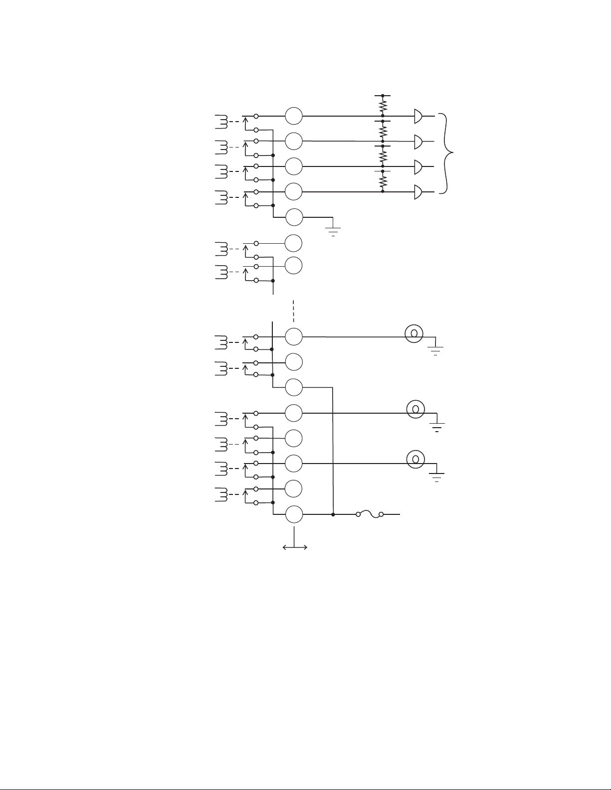
Section 4 — System Cabling
Figure 60. Tally and GPI Output Connection Example
50-pin Connector
Pin Numbers
1A of 32
21
2A of 32
3A of 32
4A of 32
5B of 32
6B of 32
27G of 32
28G of 32
29H of 32
Common A
Common B
Common G
38
22
37
39
23
48
32
47
49
5
Logic
12V Lamp
12V Lamp
30H of 32
31H of 32
32H of 32
Common H
Kayenne Video
Processor Frame
33
17
50
16
User Equipment
12V Lamp
+ 12V DC
8623266_46
The example shown in Figure 60 illustrates two common busses. The first
four outputs (COMMON A) have the common bus tied to ground. This
drives a logic system. The last outputs (COMMON G and COMMON H)
have the common bus tied to +12 volts. This drives a tally lamp system.
Although diagram shows mechanical relays, the actual outputs are implemented with solid state relays. The solid state relays are bidirectional;
either polarity voltage can be applied. If the switcher GPI/Tally outputs are
used to drive downstream DC relays, be sure to install diodes across the
64 KAYENNE — Installation Planning Guide
Page 65

relay coils to clamp inductive spikes. Shielded cable is recommended for
Pin 1Pin 5
Pin 6Pin 9
D-9 Female
the connection from the switcher to the user tally system.
Table 4. Tally and GPI Output Specifications
Pin Assignments
RS-422/485 Ports
Eight RS-422/485 ports are available on the rear of the Kayenne 8-RU and
4 RU Frames, and can be used to control various devices, or for switcher
control by an external controller.
Pin Assignments
Maximum current for any one output 1 amp AC/DC
Maximum current for any one common 2 amp AC/DC
Maximum off (open circuit) voltage between output and common 60 Volts peak
Maximum voltage between any point and ground (chassis) 60 Volts peak
One RS-422/485 port is also located on the rear of the Kayenne PCU.
Note The Frame serial port pinout is automatically configured based on assign-
ment. The Frame is the bus controller when controlling external devices,
PBus, and serial tally. The Frame is a tributary when being controlled by an
editor.
Table 5. RS-422/485 Pinouts
Socket Pin Bus Controller Tributary
1 Chassis Ground Chassis Ground
2 RxA (-) TxA (-)
3 TxB (+) RxB (+)
4 Signal Ground Signal Ground
5 Not used Not used
6 Signal Ground Signal Ground
7 RxB (+) TxB (+)
8 TxA (-) RxA (-)
9 Chassis Ground Chassis Ground
KAYENNE — Installation Planning Guide 65
Page 66
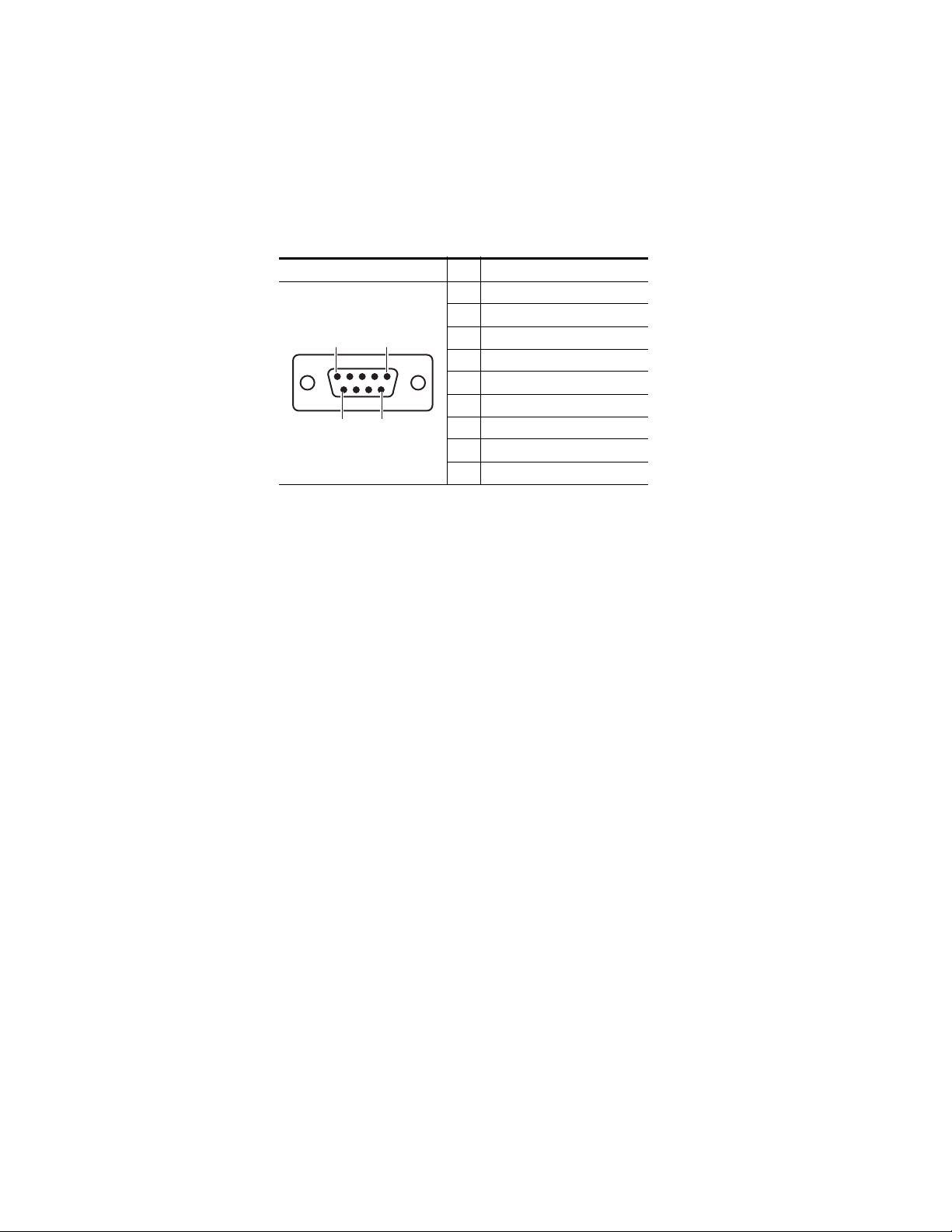
Section 4 — System Cabling
Pin 1Pin 5
Pin 6Pin 9
D-9 Female
RS-232 Ports
RS-232 serial ports are located on the front of each processor board (Video
Processor, Panel Processor, Menu Processor), and are available for mainte
nance and diagnostics.
Table 6.
Socket Pin Signal
1 Chassis Ground
2Transmit Data
3 Receive Data
4 Not used
5 Signal Ground
6 Not used
7 Clear to Send
8 Request to Send
9 Not used
-
Standard VGA and keyboard ports are also available on all processor
boards, and are also used for maintenance.
66 KAYENNE — Installation Planning Guide
Page 67
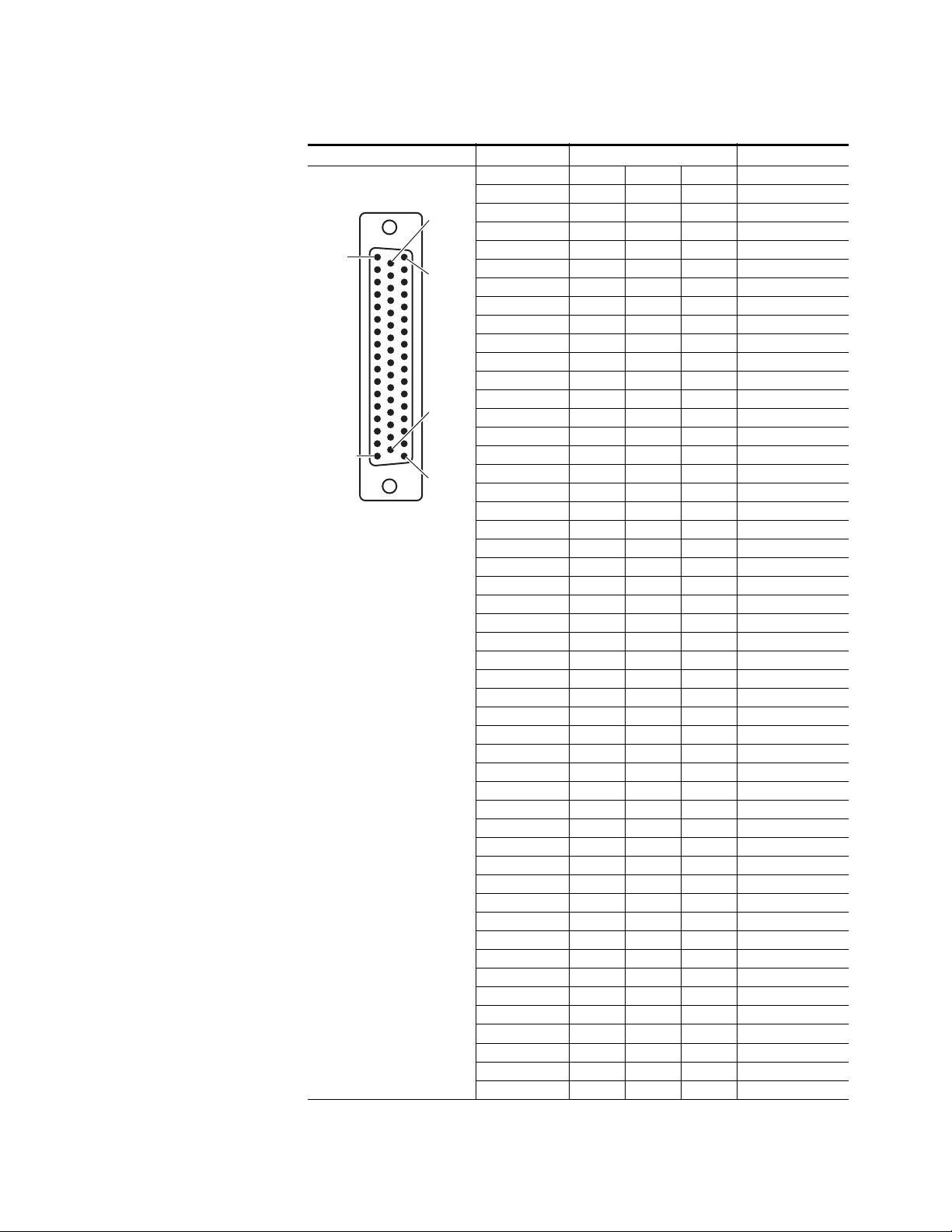
D-50 Female
Pin 1
Pin 17
Pin 33
Pin 50
Pin 18
Pin 34
Pin Assignments
4-RU and 8-RU Frame (GPI In 1-8, Tally 1-24, GPI Out 1-8)
Socket Ribbon Cable 50-Pin D-Sub Signal
1 1 GPIInCom
2 34 GPIInCom
3 18 GPIIn1
4 2 GPIIn2
5 35 GPIIn3
6 19 GPIIn4
7 3 GPIIn5
8 36 GPIIn6
9 20 GPIIn7
10 4 GPIIn8
11 37 TallyComA
12 21 Tally1A
13 5 Tally2A
14 38 Tally3A
15 22 Tally4A
16 6 TallyComB
17 39 Tally5B
18 23 Tally6B
19 7 Tally7B
20 40 Tally8B
21 24 TallyComC
22 8 Tally9C
23 41 Tally10C
24 25 Tally11C
25 9 Tally12C
26 42 TallyComD
27 26 Tally13D
28 10 Tally14D
29 43 Tally15D
30 27 Tally16D
31 11 TallyComE
32 44 Tally17E
33 28 Tally18E
34 12 Tally19E
35 45 Tally20E
36 29 TallyComF
37 13 Tally21F
38 46 Tally22F
39 30 Tally23F
40 14 Tally24F
41 47 GPIOutComG
42 31 GPIOut1G
43 15 GPIOut2G
44 48 GPIOut3G
45 32 GPIOut4G
46 16 GPIOutComH
47 49 GPIOut5H
48 33 GPIOut6H
49 17 GPIOut7H
50 50 GPIOut8H
KAYENNE — Installation Planning Guide 67
Page 68

Section 4 — System Cabling
4-RU and 8-RU Frame (GPI In 9-16, Tally 25 - 48, GPI Out 9-16)
Pin 1
Pin 17
Socket Ribbon Cable 50-Pin D-Sub Signal
1 1 GPIInCom
D-50 Female
Pin 18
Pin 34
Pin 33
Pin 50
2 34 GPIInCom
3 18 GPIIn9
4 2 GPIIn10
5 35 GPIIn11
6 19 GPIIn12
7 3 GPIIn13
8 36 GPIIn14
9 20 GPIIn15
10 4 GPIIn16
11 37 TallyComJ
12 21 Tally25J
13 5 Tally26J
14 38 Tally27J
15 22 Tally28J
16 6 TallyComK
17 39 Tally29K
18 23 Tally30K
19 7 Tally31K
20 40 Tally32K
21 24 TallyComL
22 8 Tally33L
23 41 Tally34L
24 25 Tally35L
25 9 Tally36L
26 42 TallyComM
27 26 Tally37M
28 10 Tally38M
29 43 Tally39M
30 27 Tally40M
31 11 TallyComN
32 44 Tally41N
33 28 Tally42N
34 12 Tally43N
35 45 Tally44N
36 29 TallyComP
37 13 Tally45P
38 46 Tally46P
39 30 Tally47P
40 14 Tally48P
41 47 GPIOutComQ
42 31 GPIOut9Q
43 15 GPIOut10Q
44 48 GPIOut11Q
45 32 GPIOut12Q
46 16 GPIOutComR
47 49 GPIOut13R
48 33 GPIOut14R
49 17 GPIOut15R
50 50 GPIOut16R
68 KAYENNE — Installation Planning Guide
Page 69

D-50 Female
Pin 1
Pin 17
Pin 33
Pin 50
Pin 18
Pin 34
Pin Assignments
8-RU Frame (GPI In 17-24, Tally 49 - 72, GPI Out 17-24)
Socket Ribbon Cable 50-Pin D-Sub Signal
1 1 GPIInCom
2 34 GPIInCom
3 18 GPIIn17
4 2 GPIIn18
5 35 GPIIn19
6 19 GPIIn20
7 3 GPIIn21
8 36 GPIIn22
9 20 GPIIn23
10 4 GPIIn24
11 37 TallyComS
12 21 Tally49S
13 5 Tally50S
14 38 Tally51S
15 22 Tally52S
16 6 TallyComT
17 39 Tally53T
18 23 Tally54T
19 7 Tally55T
20 40 Tally56T
21 24 TallyComU
22 8 Tally57U
23 41 Tally58U
24 25 Tally59U
25 9 Tally60U
26 42 TallyComV
27 26 Tally61V
28 10 Tally62V
29 43 Tally63V
30 27 Tally64V
31 11 TallyComW
32 44 Tally65W
33 28 Tally66W
34 12 Tally67W
35 45 Tally68W
36 29 TallyComX
37 13 Tally69X
38 46 Tally70X
39 30 Tally71X
40 14 Tally72X
41 47 GPIOutComY
42 31 GPIOut17Y
43 15 GPIOut18Y
44 48 GPIOut19Y
45 32 GPIOut20Y
46 16 GPIOutComZ
47 49 GPIOut21Z
48 33 GPIOut22Z
49 17 GPIOut23Z
50 50 GPIOut24Z
KAYENNE — Installation Planning Guide 69
Page 70
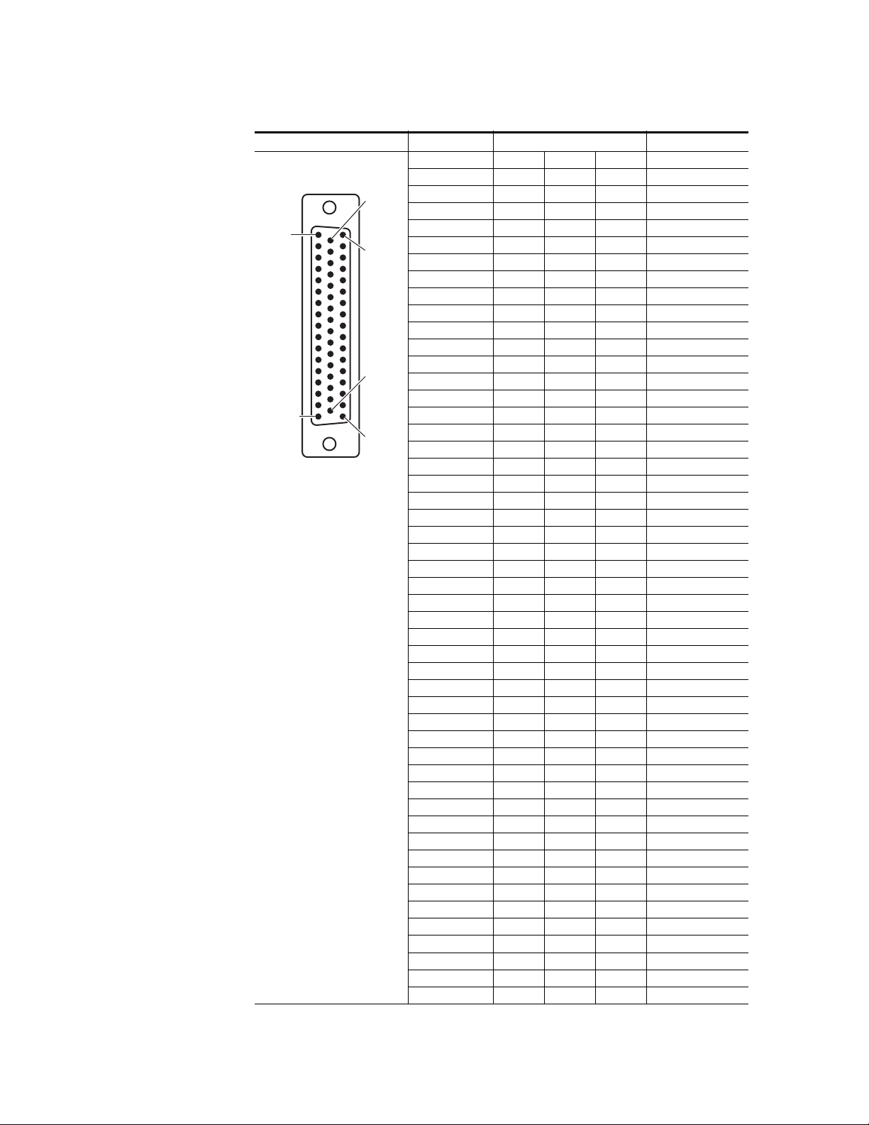
Section 4 — System Cabling
8-RU Frame (GPI In 25-32, Tally 73 - 96, GPI Out 25 - 32)
Pin 1
Pin 17
Socket Ribbon Cable 50-Pin D-Sub Signal
1 1 GPIInCom
D-50 Female
Pin 18
Pin 34
Pin 33
Pin 50
2 34 GPIInCom
3 18 GPIIn25
4 2 GPIIn26
5 35 GPIIn27
6 19 GPIIn28
7 3 GPIIn29
8 36 GPIIn30
9 20 GPIIn31
10 4 GPIIn32
11 37 TallyComAA
12 21 Tally73AA
13 5 Tally74AA
14 38 Tally75AA
15 22 Tally76AA
16 6 TallyComAB
17 39 Tally77AB
18 23 Tally78AB
19 7 Tally79AB
20 40 Tally80AB
21 24 TallyComAC
22 8 Tally81AC
23 41 Tally82AC
24 25 Tally83AC
25 9 Tally84AC
26 42 TallyComAD
27 26 Tally85AD
28 10 Tally86AD
29 43 Tally87AD
30 27 Tally88AD
31 11 TallyComAE
32 44 Tally89AE
33 28 Tally90AE
34 12 Tally91AE
35 45 Tally92AE
36 29 TallyComAF
37 13 Tally93AF
38 46 Tally94AF
39 30 Tally95AF
40 14 Tally96AF
41 47 GPIOutComAG
42 31 GPIOut25AG
43 15 GPIOut26AG
44 48 GPIOut27AG
45 32 GPIOut28AG
46 16 GPIOutComAH
47 49 GPIOut29AH
48 33 GPIOut30AH
49 17 GPIOut31AH
50 50 GPIOut32AH
70 KAYENNE — Installation Planning Guide
Page 71

Specifications
Table 7. Kayenne Mechanical Specifications
Component Depth Width Height Weight
Control Panels
4 ME-35, with attached
Local Aux Stripe, 15 m Cables
3 ME-35, with
Local Aux Stripe, 15 m Cables
2 ME-25, with
Local Aux Stripe, 15 m Cables
1 ME-15,with 15 m Cables,
without Local Aux Stripe
Local Aux Stripe
Local Aux-35
with 15 m Cable
Local Aux-25
with 15 m Cable
Menu Panel
Touch Screen
with 15 m cable
Menu Panel Support Arm
Panel Control Unit (PCU)
Kayenne 4-RU Frame
Kayenne 8-RU Frame
a
All weights approximate.
Appendix A
Curved Support Structure Orientation
746.3 mm
(29.38 in.)
637.1 mm
(25.08 in.)
488.4 mm
(19.23 in.)
356.4 mm
(14.03 in.)
185.7 mm
(7.31 in.)
185.7 mm
(7.31 in.)
91.7 mm
(3.612 in.)
n/a n/a n/a 4.8 kg
588.52 mm
(23.17 in.)
546.10 mm
(21.5 in.)
522.73 mm
(20.58 in.)
1533.7 mm
(60.38 in.)
1533.7 mm
(60.38 in.)
1341.7 mm
(52.82 in.)
758.3 mm
(29.85 in.)
Separately Mounted, Flat Orientation
813.7 mm
(32.04 in.)
621.7 mm
(24.48 in.)
417.85 mm
(16.45 in.)
482.60 mm
(19 in.)
482.60 mm
(19 in.)
482.60 mm
(19 in.)
559.3 mm
(22.02 in.)
292.3 mm
(11.51 in.)
242.3 mm
(9.54 in.)
84.3 mm
(3.32 in.)
84.3 mm
(3.32 in.)
84.3 mm
(3.32 in.)
270.10 mm
(10.63 in.)
132.59 mm
(5.22 in.)
177.80 mm
(7 in.)
441.96 mm
(17.4 in.)
57.3 kg
(126.2 lbs.)
44.7 kg
(98.4 lbs.)
29.9 kg
(65.8 lbs.)
14.5 kg
(32.0 lbs.)
6.3 kg
(13.8 lbs.)
6.1
(13.4 lbs.)
6.2 kg
(13.5 lbs)
(10.5 lbs)
16.1 kg
(35.4 lbs)
17.7 kg
(39 lbs)
30.4 kg
(67 lbs)
a
Rack Units
n/a
n/a
n/a
n/a
n/a
n/a
n/a
n/a
3
4
8
Table 8. Environmental
Storage temperature -20 to 70 deg C (-4 to 158 deg F)
Operating temperature 0 to 40 deg C (32 to 104 deg F)
Relative humidity 0-95% (non-condensing)
Electromagnetic environment E2 (according to EN55103-1, -2)
KAYENNE — Installation Planning Guide 71
Page 72

Appendix A — Specifications
Table 9. Network Connections
Type of connection 10/100/1000 Base T
Protocol TCP(UDP)/IP, Auto speed detection. Auto crossover cable configuration.
Cable and connectors CAT5 UTP, RJ45 connectors;
Max. Cable Length 100m / 300ft
Note
The Video Processor Frame and the PCU Frame each have an internal Ethernet switch. The VP Frame has four
available external ports on its switch, two of which are to be used with each PCU (two PCUs maximum). The PCU
has six available external ports on its internal switch, and one additional port dedicated for Control Panel use.
When a PCU is attached to the VP Frame, five PCU ports remain available for additional network connections.
Table 10. PCU Interconnects
Control Panel - PCU Connections
Cable and connectors Custom 7 Pin D style
Number Required 1 for each Control Panel Stripe, Local Aux Stripe, and Satellite Panel
Max. Interconnect Cable Length 15 m / 50 ft. (7.5 m / 25 ft. cable length also available)
Cable Weight
15 m / 50 ft. 1.3 kg (2.9 lbs)
7.5 m / 25 ft. 0.7 kg (1.6 lbs.)
Touch Screen Menu Panel - PCU Connection
Cable and connectors Custom 17 Pin D style
Number Required 1 for each Menu Panel (2 maximum)
Max. Interconnect Cable Length 15m / 50ft (7.5m / 25ft cable length also available)
Cable Weight
15 m / 50 ft. 1.6 kg (3.7 lbs)
7.5 m / 25 ft. 0.9 kg (2.0 lbs.)
Table 11. Power
4-RU Video Processor Frame
Line voltage
Line frequency 50/60Hz +/- 5%
Power consumption max. 400W
Leakage current < 2.5 mA
100V-240V AC +/-10% autorange, power factor corrected. Automatic linevoltage sensing for 120V and 240V sources.
8-RU Video Processor Frame
Line voltage
Line frequency 50/60Hz +/- 5%
Power consumption max. 1000W
Leakage current < 2.5 mA
100V-240V AC +/-10% autorange, power factor corrected. Automatic linevoltage sensing for 120V and 240V sources.
Panel Control Unit (required for Control Panel and Touch Screen Menu Panel Operation)
Line voltage
Line frequency 50/60Hz +/- 5%
Power consumption max. 500W
Leakage current < 2.5 mA
100V-240V AC +/-10% autorange, power factor corrected. Automatic linevoltage sensing for 120V and 240V sources.
72 KAYENNE — Installation Planning Guide
Page 73

Table 12. Serial Digital Video Inputs
Format
Number of Inputs
Return loss > 15 db, 5 MHz to 1.5 GHz
Type of Connector 75 ohm BNC (SMPTE 259M)
Interface
Nominal Amplitude 800mV peak-to-peak terminated
Channel Coding conforms to SMPTE 259M, SMPTE 292M
Ancillary Data Blanked or passed (user selectable)
Embedded audio Blanked or passed (user selectable)
EDH Blanked
Input Impedance 75 ohm
Max cable length
ITU-R656, SMPTE 259M, 270 Mbit/s.
SMPTE 292M, 1.485 Gbit/s
Frame w/ 1 ME Board: 24
Frame w/ 2 ME Boards: 48
Frame w/ 3 ME Boards: 72
Frame w/ 4 ME Boards: 96
HD Video Formats SMPTE 292M-1998
SD Video Formats SMPTE 259M-1997
HD Video 100 meters using Belden 1694A type cable
SD Video 300 meters using Belden 1694A type cable
Table 13. Serial Digital Video Outputs
Format
Number of Outputs
Return loss > 15 db, 5 MHz to 1.5 GHz
Type of Connector 75 ohm BNC (SMPTE 259M)
Interface
Nominal Amplitude 800 mv peak-to-peak across 75 ohm +/- 10%
Rise & Fall Times
Jitter ITU R 601/656
Output Impedance 75 ohm
DC Offset < 50mV with 75 ohm termination
ITU-R656, SMPTE 259M, 270 Mbit/s.
SMPTE 292M, 1.485 Gbit/s
Frame w/ 1 ME Board: 12
Frame w/ 2 ME Boards: 24
Frame w/ 3 ME Boards: 36
Frame w/ 4 ME Boards: 48
HD Video Formats SMPTE 292M-1998
SD Video Formats SMPTE 259M-1997
400 to 1400picoseconds 75 ohm termination
between 20% and 80% amplitude
KAYENNE — Installation Planning Guide 73
Page 74
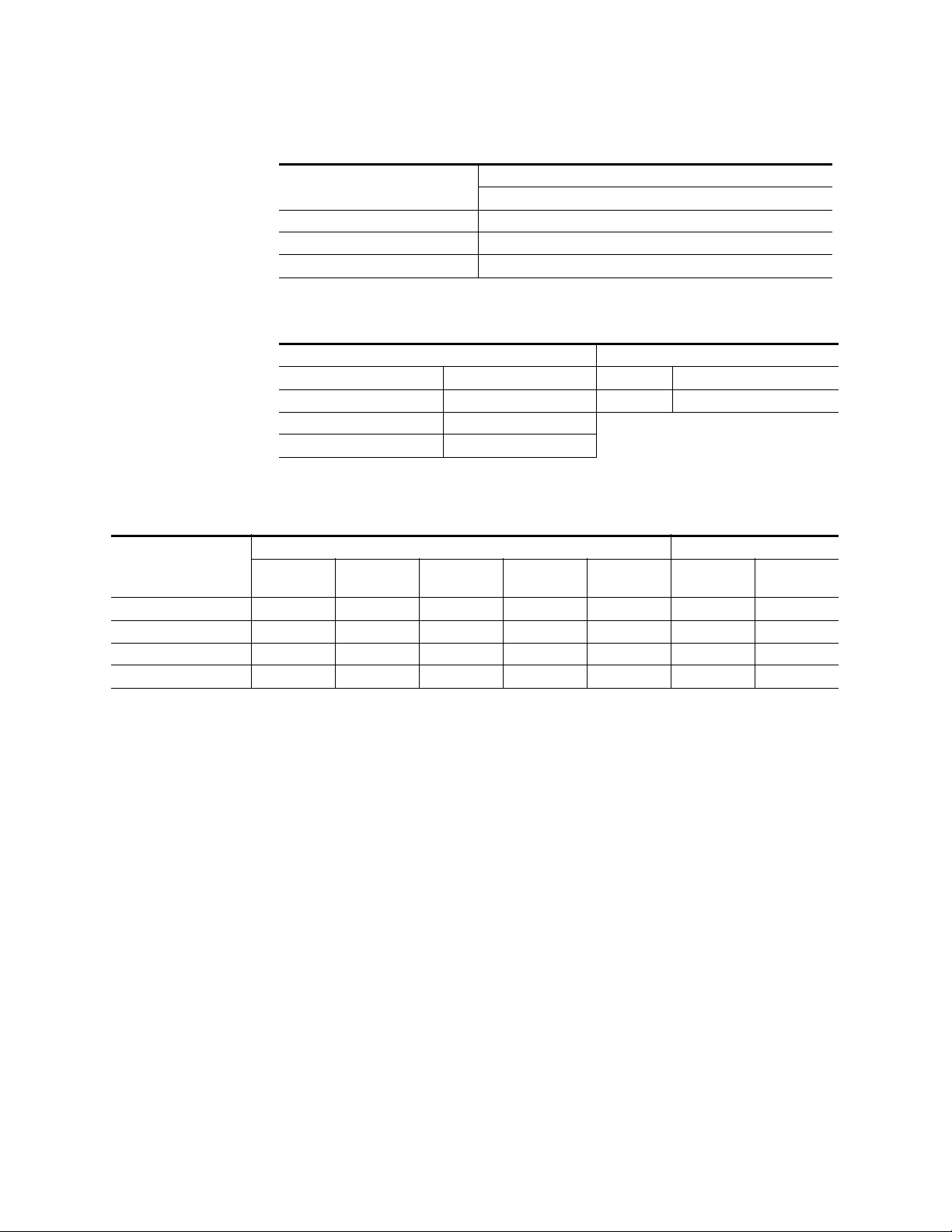
Appendix A — Specifications
Table 14. Analog Reference Input
Video Standard
Return loss > 40dB, up to 5 MHz
Connectors 2 each BNC loop through for both HD and SD inputs
Impedance 75 ohm external
Table 15. Kayenne Video Standards
HD Mode SD Mode
1080i 29.97/30 SMPTE 274M Table 4, 5 525i 29.97 SMPTE 259M
1080i 25 SMPTE 274M Table 6 625i 25 SMPTE 259M
1080sF 23.97/24/25/29.97/30 SMPTE RP211 Table 12-16
720p 50/59.94/60 SMPTE 296 Table 1-3
For HD Video: Tri-level Sync, Analog equivalent to the standard being used
For SD Video: Color Black, Analog equivalent to the standard being used
Table 16. Kayenne System Timing, 4.5 ME System
HD Mode SD Mode
System Timing
Nominal Switcher Delay 21.96 µs 19.79 µs 26.46 µs 23.50 µs 27.20 µs 61.46 µs 61.68 µs
Serial Input Autotiming +/- 4.71 µs +/- 2.45 µs +/- 9.12 µs +/- 6.16 µs +/- 9.86 µs +/- 2.10 µs +/- 2.32 µs
Minimum Switcher Delay 17.34 µs 17.34 µs 17.34 µs 17.34 µs 17.34 µs 59.36 µs 59.36 µs
~ Maximum Switcher Delay 26.67 µs 22.24 µs 35.56 µs 29.66 µs 37.04 µs 63.56 µs 64.00 µs
720p/
50
720p/
59.94/60
1080i & sf/251080i & sf/
29.97/30
1080sf/
23.97/24
525i/
29.97
625i/
25
74 KAYENNE — Installation Planning Guide
Page 75

Index
Numerics
1-ME 15 Control Panel 33
2-ME 25 Control Panel 32
2-ME 35 Control Panel
curved assembly
flat assembly 29
flat assembly no Local Aux 31
30mm components 15
3-ME 25 Control Panel 26
3-ME 35 Control Panel
curved assembly
flat assembly 24
4-ME 25 Control Panel 21
4-ME 35 Control Panel
curved assembly
flat assembly 19
4-RU Frame
connectors
cooling 46
dimensions 45
door clearance 46
installation 45
power supply 48
rack mounting 46
75-ohm termination 61
8-RU Frame
connectors
cooling 42
dimensions 40
door clearance 42
installation 40
power supply 44
rack mounting 42
A
ambient temperature
maximum
articulated arm
assembly with Menu Panel
used with Menu Panel 13
39
47
43
27
22
17
36
B
Bosch Rexroth 15
C
cabling
control surface
network 54
overview 53
suite 55
commissioning
and Control Panel assembly
connectors
8-RU Frame
PCU 51
control interfaces 14
Control Panel
assembly
assembly variations 16
commissioning includes assembly 15
cooling 16
curved 11
electronics in PCU 15
flat 11
general description 15
module types 12
Stripe to PCU connection 34
Stripe to PCU connections 59
support component size 15
support structure assembly 15
truck vibration considerations 16
control surface
cabling
components 15
definition 10
examples 10
cooling
4-RU Frame
8-RU Frame 42
Control Panel 16
Frame 39
PCU 50
55
55
15
43
15
46
KAYENNE — Installation Planning Guide 75
Page 76

Index
D
default 58
default IP address 58
default network settings 58
dimensions
4-RU Frame
8-RU Frame 40
articulated arm for Menu Panel 37
Menu Panel 35
PCU 48
documentation online 4
door clearance
4-RU Frame
8-RU Frame 42
PCU 50
45
46
E
Ethernet
subnet mask
Ethernet router 56
Ethernet switch 56
58
GPI Out port
pinouts
GPI/Tally interface 61
Grass Valley web site 4
67
H
high vibration environment 16
I
inputs
GPI
62
video cabling 60
IP address
default
58
K
Kayenne system overview 9
L
F
factory default network settings 58
FAQ database 4
format conversion 61
connectors 61
Frame
cooling
power 39
power supply 39
weight distribution 39
frequently asked questions 4
39
G
GPI
connections
inputs 62
outputs 63
GPI In port
pinouts
GPI out
circuitry
62
67
63
line rate signal format conversion 61
Local Aux Stripe
connection to PCU
mounted separately 34
mounting options 16
Loctite Blue 242 16
59
M
MatchDef
connectors
maximum ambient temperature 39
ME Stripe 12
connectionsto PCU 59
Menu application 13
Menu Panel
additional
articulated arm 13
articulated arm assembly 36
articulated arm dimensions 37
connectors 35
cooling 36
dimensions 35
electronics in PCU 15
61
13, 37
76 KAYENNE — Installation Planning Guide
Page 77

Index
installation 35
PCU cabling 60
touch screen 13
multi-pin cable
maximum length
N
network
cabling
network cabling 54
network settings 58
54
O
online documentation 4
outputs
63
GPI
Tally 63
video cabling 60
P
Panel Control Unit
see PCU
PCU
connections to Stripes
connectors 51
Control Panel electronics 15
cooling 50
dimensions 48
door clearance 50
general description 13
installation 48
Menu Panel electronics 15
power supply 52
rack nounting 50
Stripe connection 34
use of second for suite 56
pin assignments 65
pinouts 65
GPI In 67
GPI Out 67
RS-232 66
RS-422/485 65
Tally 67
power
for Frame
39
55
59
power supply
4-RU Frame
8-RU Frame 44
Frame 39
PCU 52
protocols
control
48
14
R
rack mounting
4-RU Frame
8-RU Frame 42
general instructions 39
PCU 50
redundant power supply
for frames
reference
video cabling
router
Ethernet
RS-232 port
pinouts
RS-422/485 port
pinouts
46
14
61
56
66
65
S
serial tally interface 61
SetDef
connectors
software download from web 4
specifications 71
Stripe
boxed for shipment
connection to PCU 34
connections to PCU 59
defined 12
Local Aux 16
ME 12
subnet mask 58
suite
cabling
definition 11
uses of second PCU 56
support assembly
30mm components
61
15
55
15
KAYENNE — Installation Planning Guide 77
Page 78

Index
support structure assembly
for Control Panel
switch
Ethernet
system communications 53
system overview 9
56
15
T
Tally
outputs
tally
connections
serial 61
Tally out
circuitry
Tally port
pinouts
Tally/GPI 61
touch screen Menu Panel 13
tri-level sync 61
truck installation
vibration considerations
63
62
63
67
16
V
video cabling 60
inputs 60
MatchDef, SetDef connectors 61
outputs 60
reference input 61
Video Processor
4-RU Frame installation
8-RU Frame installation 40
Video Processor Frame
general description
45
9
W
web site documentation 4
web site FAQ database 4
web site Grass Valley 4
web site software download 4
weight distribution
Frame
39
78 KAYENNE — Installation Planning Guide
 Loading...