

Page 1
KayakDD-1™
DIGITAL PRODUCTION SWITCHER
Planning and Installation Manual
SOFTWARE VERSION 6.7.1
071826305
JUNE 2005
Page 2

KayakDD-1 Digital Production Switcher
Contacting Grass Valley
Region Voice Fax Address Web Site
North America (800) 547-8949
Support: 530-478-4148
Pacific Operations +852-2585-6688
Support: +852-2585-6579
U.K., Asia, Middle East +44 1753 218 777 +44 1753 218 757
France +33 1 45 29 73 00
Germany, Europe +49 6150 104 782 +49 6150 104 223
Copyright © Thomson Broadcast and Media Solutions All rights reserved.
Grass Valley Web Site
The www.thomsongrassvalley.com web site offers the following:
Sales: (530) 478-3347
Support: (530) 478-3181
+852-2802-2996
Grass Valley
P.O. Box 599000
Nevada City,
CA 95959-7900
USA
www.thomsongrassvalley.com
Online User Documentation — Current versions of product catalogs, brochures, data sheets, ordering
guides, planning guides, manuals, and release notes in .pdf format can be downloaded.
FAQ Database — Solutions to problems and troubleshooting efforts can be found by searching our
Frequently Asked Questions (FAQ) database.
Software Downloads — Software updates, drivers, and patches can be downloaded.
2 Planning and Installation Manual
Page 3

Number: 510057.001
The Quality System of:
Thomson Broadcast & Media Solutions
TBMS TBMS
400 Providence Mine Road 17 rue du Petit Albi -BP 8244
Nevada City, CA 95945 95801 Cergy Pontoise
Cergy, France
TBMS
Weiterstadt, Germany TBMS
Brunnenweg 9 10 Presidential Way, 3rd Floor, Suite 300
D-64331 Weiterstadt, Germany Woburn, MA 08101
TBMS TBMS
15655 SW Greystone Ct. 2300 South Decker Lake Blvd.
Beaverton, OR 97006 Salt Lake City, UT 84119
TBMS TBMS - PCB
Nederland B.V. Rennes, France
4800 RP BREDA Rue du Clos Courtel
The Nederlands Cesson-Sevigne, Cedex
France
TBMS/Nextream TBMS/Nextream
Rennes, France Technopole Brest Iroise
Rue du Clos Courtel CS 73808
Cesson-Sevigne, Cedex 29238 Brest Cedex 3
France France
Including its implementation, meets the requirements of the standard:
ISO 9001:2000
Scope: The design, manufacture and support of video hardware and software products
and related systems.
This Certificate is valid until: June 14, 2006
Revision Date: September 9, 2003
Renewal Date: June 14, 2003
Issued for the first time: June 14, 2000
Page 4

KayakDD-1 Digital Production Switcher
Table of Contents
1 PREFACE .........................................................................................................................................................9
1.1 ABOUT THIS MANUAL....................................................................................................................................9
1.2 STANDARD DOCUMENTATION SET.................................................................................................................9
1.3 OTHER DOCUMENTATION..............................................................................................................................9
2 REGULATORY NOTICES..............................................................................................................................11
2.1 CERTIFICATIONS AND COMPLIANCES ...........................................................................................................11
2.1.1 FCC Emission Control......................................................................................................................11
2.1.2 Canadian EMC Notice of Compliance..............................................................................................11
2.1.3 FCC Emission Limits ........................................................................................................................11
2.1.4 Certification and Compliance............................................................................................................12
3 SAFETY SUMMARY.......................................................................................................................................15
3.1 SAFETY TERMS AND SYMBOLS....................................................................................................................15
3.1.1 Terms in This Manual.......................................................................................................................15
3.1.2 Terms on the Product.......................................................................................................................15
3.1.3 Symbols on the Product....................................................................................................................16
3.2 WARNINGS.................................................................................................................................................17
3.3 CAUTIONS..................................................................................................................................................18
4 TECHNICAL SPECIFICATION.......................................................................................................................19
4.1 POWER SUPPLY FRAME..............................................................................................................................19
4.2 POWER SUPPLY PANEL ..............................................................................................................................19
4.3 ENVIRONMENTAL DATA...............................................................................................................................19
4.4 VIDEO SYSTEM DATA..................................................................................................................................20
4.5 SERIAL DIGITAL VIDEO INPUTS....................................................................................................................20
4.6 SERIAL DIGITAL VIDEO OUTPUTS ................................................................................................................21
4.7 ANALOG REFERENCE INPUT........................................................................................................................21
4.8 CONTROL PANEL CONNECTION...................................................................................................................21
4.9 MECHANICAL DATA.....................................................................................................................................22
5 SYSTEM OVERVIEW.....................................................................................................................................23
5.1 INTRODUCTION...........................................................................................................................................23
5.1.1 Features............................................................................................................................................23
5.1.2 Supported Control Protocols.............................................................................................................24
5.1.3 KayakDD-1 Ordering Information.....................................................................................................25
5.2 SYSTEM COMPONENTS...............................................................................................................................26
5.3 CONTROL SURFACE ...................................................................................................................................27
5.4 VIDEO PROCESSOR FRAME.........................................................................................................................28
5.4.1 System Components ........................................................................................................................29
5.4.2 Video Processor Frame Options.......................................................................................................29
5.5 FUNCTIONAL OVERVIEW .............................................................................................................................30
5.5.1 Video Signal Flow.............................................................................................................................30
5.5.2 System Control.................................................................................................................................31
Planning and Installation Manual 3
Page 5

KayakDD-1 Digital Production Switcher
6 INSTALLATION ............................................................................................................................................. 33
6.1 PRE-INSTALLATION PROCEDURES .............................................................................................................. 33
6.1.1 System Survey................................................................................................................................. 33
6.1.2 Line Voltage..................................................................................................................................... 33
6.1.3 Safety Requirements........................................................................................................................ 33
6.1.4 Installation Tasks ............................................................................................................................. 34
6.2 MOUNTING THE PROCESSOR FRAME .......................................................................................................... 35
6.2.1 Video Processor Frame Measurements.......................................................................................... 35
6.2.2 General Rack Mounting Instructions................................................................................................ 36
6.2.3 Rack Mounting Procedure ............................................................................................................... 37
6.3 MOUNTING THE CONTROL PANEL ............................................................................................................... 38
6.3.1 Control Panel Measurements .......................................................................................................... 38
6.3.2 Table Top Mounting......................................................................................................................... 40
6.3.3 Cut Out Dimensions for Surface Mounting...................................................................................... 40
6.3.4 Mounting Holes for Panel Fastening................................................................................................ 40
6.4 CONTROL PANEL CONNECTORS ................................................................................................................. 42
6.5 PROCESSOR FRAME CONNECTORS ............................................................................................................ 44
6.6 PIN ASSIGNMENTS..................................................................................................................................... 46
6.6.1 RS 485 Port...................................................................................................................................... 46
6.6.2 RS 232 Port...................................................................................................................................... 46
6.6.3 Panel DC Power In........................................................................................................................... 47
6.6.4 Frame DC Power In......................................................................................................................... 47
6.6.5 Frame DC Power Out.......................................................................................................................47
6.6.6 Frame GPI/O – Tally........................................................................................................................ 48
6.7 CABLING AND CONTROL............................................................................................................................. 49
6.7.1 Cabling............................................................................................................................................. 49
6.7.2 Control Cabling ................................................................................................................................50
6.7.3 Video................................................................................................................................................52
6.7.4 Video Timing and Delay................................................................................................................... 53
6.7.5 GPI / Tally Outputs........................................................................................................................... 54
6.7.6 GPI Inputs........................................................................................................................................ 54
6.7.7 Tally Adapter.................................................................................................................................... 54
7 SERVICE INSTRUCTIONS............................................................................................................................ 55
7.1 RUNNING PANEL TESTS............................................................................................................................. 55
7.1.1 Local Panel Test Mode 1 (Button Test)........................................................................................... 56
7.1.2 Local Panel Test Mode 2 (LED Test)............................................................................................... 56
7.1.3 Local Panel Test Mode 3 (Group Test / On Air Highlight Test):...................................................... 56
7.1.4 Local Panel Test Mode 4 (Connect Mode)...................................................................................... 56
7.1.5 Local Panel Test Mode 5 (Colour Test)........................................................................................... 57
7.2 SOFTWARE-UPDATE ..................................................................................................................................58
7.2.1 Recommended Memory Sticks........................................................................................................ 58
7.2.2 Preparing the USB Memory Stick.................................................................................................... 58
7.2.3 Software Loading/Update ................................................................................................................ 62
7.2.4 Installation Procedure...................................................................................................................... 63
7.2.5 Updating the CPLD Firmware.......................................................................................................... 66
7.3 DEVICE CONFIGURATION............................................................................................................................ 67
7.3.1 Configure Device Menu ................................................................................................................... 67
7.3.2 Reset / Check / Clear Device Menu................................................................................................ 68
4 Planning and Installation Manual
Page 6

KayakDD-1 Digital Production Switcher
7.4 T
ROUBLE SHOOTING ..................................................................................................................................69
7.4.1 How to Calibrate the TouchScreen...................................................................................................69
7.4.2 Lost LAN Connection........................................................................................................................69
7.4.3 Problems with Network Configuration ..............................................................................................69
7.4.4 How to Connect a PC / Laptop to the KayakDD...............................................................................71
7.4.5 CPLD Update Trouble Shooting.......................................................................................................73
7.4.6 How to Install the Sidepanel Software to a PC / Laptop...................................................................74
7.4.7 Network Problems with Sidepanel....................................................................................................77
7.4.8 Lifetime of the Internal Battery..........................................................................................................79
7.4.9 Exchange the Battery .......................................................................................................................79
7.4.10 iButton Exchange for Spare Part Mainframe....................................................................................84
7.5 CONTROL INTERFACES ...............................................................................................................................85
7.5.1 Supported GVG100 Commands.......................................................................................................85
7.5.2 Supported GVG200 Commands.......................................................................................................87
Planning and Installation Manual 5
Page 7

KayakDD-1 Digital Production Switcher
Table of Figures
Figure 1 Video Processor Frame and Control Panel..................................................................................... 26
Figure 2 Control Panel ................................................................................................................................... 26
Figure 3 KayakDD-1 Control Panel Surface .................................................................................................. 27
Figure 4 KayakDD-1 Video Processor Frame................................................................................................ 28
Figure 5 KayakDD Simplified Video Flow Diagram........................................................................................ 31
Figure 6 KayakDD-1 Video Processor Frame Dimensions............................................................................ 35
Figure 7 KayakDD-1 Video Processor Frame Rack Mounting....................................................................... 37
Figure 8 KayakDD-1 Control Panel Measurements 1 of 2............................................................................. 38
Figure 9 KayakDD-1 Control Panel Measurements 2 of 2............................................................................. 39
Figure 10 Bottom View, Position of the Mounting Points................................................................................. 40
Figure 11 Bottom View, Measurements of the Mounting Points...................................................................... 41
Figure 12 Panel Fastening Procedure ............................................................................................................. 41
Figure 13 Control Panel Connectors................................................................................................................ 42
Figure 14 Video Processor Frame Connectors................................................................................................ 44
Figure 15 KayakDD-1 Standard Cabling.......................................................................................................... 49
Figure 16 Timing and Delay............................................................................................................................. 53
Figure 17 Tally Adapter Cable.......................................................................................................................... 54
Figure 18 KayakDD Control Panel Detail – Transition Panel........................................................................... 55
Figure 19 Device Control Menu........................................................................................................................61
Figure 20 Device Control Menu with Software Update Dialog......................................................................... 62
Figure 21 Start Installation Procedure..............................................................................................................63
Figure 22 Installation Procedure...................................................................................................................... 63
Figure 23 Cancel Installation Procedure.......................................................................................................... 64
Figure 24 Device Control Installation Status.................................................................................................... 64
Figure 25 Finish Installation............................................................................................................................. 65
Figure 26 CPLD Update................................................................................................................................... 66
Figure 27 Configure Devices............................................................................................................................ 67
Figure 28 Reset/Clear/Check Devices Menu................................................................................................... 68
Figure 29 PC Connection................................................................................................................................. 71
Figure 30 Error Message during CPLD update................................................................................................ 73
Figure 31 Path to the NetCheck Software........................................................................................................ 77
Figure 32 NetCheck Window............................................................................................................................ 78
Figure 33 KayakDD-1 Frame Front.................................................................................................................. 79
Figure 34 KayakDD1-Frame Without Front Plate ............................................................................................ 79
Figure 35 KayakDD-1 Control Panel................................................................................................................ 80
Figure 36 Battery on the Board of the Control Panel....................................................................................... 80
Figure 37 PS2 and VGA sockets on the KayakDD-1 Frame ........................................................................... 81
Figure 38 PS2 and VGA sockets on the KayakDD-1 Panel............................................................................. 82
Figure 39 Install – Config Device Menu........................................................................................................... 83
Figure 40 KayakDD-1 Frame Front View......................................................................................................... 84
Figure 41 Position of the iButton...................................................................................................................... 84
6 Planning and Installation Manual
Page 8
KayakDD-1 Digital Production Switcher
Planning and Installation Manual 7
Page 9

KayakDD-1 Digital Production Switcher
8 Planning and Installation Manual
Page 10

1 Preface
1.1 About This Manual
This KayakDD Planning and Installation Manual provides installation, configuration,
and service information for the Thomson Grass Valley KayakDD-1 Digital Production
Switcher. This manual is designed for technical personnel responsible for installing and
maintaining KayakDD systems.
1.2 Standard Documentation Set
The standard KayakDD-1 documentation set consists of a:
• Operating Instructions,
• Planning and Installation Manual, and
• Release Notes.
The Operating Instructions contains background information about the KayakDD
Digital Production switcher family and describes operating procedures. This manual
can be used while learning about KayakDD and for enhancing your basic knowledge of
the system.
The Planning and Installation Manual contains information about installing, configuring,
and maintaining the system. The service part in this current manual is in preparation.
The Release Notes contain information about new features and system enhancements
for a specific software version, and also includes software installation procedures.
Always check the release notes for your current system software before you begin
operating your system.
KayakDD-1 Digital Production Switcher
1.3 Other Documentation
Communication protocols of KayakDD are available upon request for developers and
software engineers to use to design editor and other external interfaces to the
KayakDD system.
Planning and Installation Manual 9
Page 11

KayakDD-1 Digital Production Switcher
10 Planning and Installation Manual
Page 12

KayakDD-1 Digital Production Switcher
2 Regulatory Notices
2.1 Certifications and Compliances
2.1.1 FCC Emission Control
This equipment has been tested and found to comply with the limits for a Class A
(Control Panel) and Class B (Mainframe) digital device, pursuant to Part 15 of the FCC
Rules. These limits are designed to provide reasonable protection against harmful
interference when the equipment is operated in a commercial environment. This
equipment generates, uses, and can radiate radio frequency energy and, if not
installed and used in accordance with the instruction manual, may cause harmful
interference to radio communications. Operation of this equipment in a residential area
is likely to cause harmful interference in which case the user will be required to correct
the interference at his own expense.
Changes or modifications not expressly approved by Thomson Grass Valley can affect
emission compliance and could void the user’s authority to operate this equipment.
2.1.2 Canadian EMC Notice of Compliance
This digital apparatus does not exceed the Class A (Control Panel) and Class B
(Mainframe) limits for radio noise emissions from digital apparatus set out in the Radio
Interference Regulations of the Canadian Department of Communications.
Le présent appareil numérique n’emet pas de bruits radioélectriques dépassant hors
des limites applicables aux appareils numériques de la classe A pour des pupitre de
control et classe B pour le rack préscrites dans le Règlement sur le brouillage
radioélectrique édicte par le ministère des Communications du Canada.
2.1.3 FCC Emission Limits
This device complies with Part 15 of the FCC 47 Rules. Operation is subject to the
following two conditions: (1) This device may no cause harmful interference, and (2)
this device must accept any interference received, including interference that may
cause undesirable operation.
Planning and Installation Manual 11
Page 13

KayakDD-1 Digital Production Switcher
2.1.4 Certification and Compliance
This product has been evaluated for Electromagnetic Compatibility under the EN
55103-1/2 standards for Emissions and Immunity and meets the requirements for
E1/E2 environment.
This product complies with Class A (Control Panel) and Class B (Mainframe). In a
domestic environment this product may cause radio interference in which case the
user may be required to take adequate measures.
This product has been evaluated and meets the following Safety Certification
Standards:
Category Standard Designed/tested for compliance with
Safety ANSI / UL60950
IEC 60950
73/23/EEC Low Voltage Directive
CAN/CSA C22.2,
No. 60950-00
Europe:
EN 60950
Safety of Information Technology Equipment,
including Electrical Business Equipment.
Safety of Information Technology Equipment,
including Electrical Business Equipment
Safety of Information Technology Equipment,
including Electrical Business Equipment.
Safety of Information Technology Equipment,
including Electrical Business Equipment.
12 Planning and Installation Manual
Page 14

KayakDD-1 Digital Production Switcher
Category Standard Designed/tested for compliance with
EMI
EMC Directive
89/336/EEC via
Audio, Video and Entertainment Lighting
Control for the European Community.
EN 55103-1 and 2
EN 55103-1
standards
Electromagnetic compatibility.
Product family standard for audio, video, audiovisual and entertainment lighting control
apparatus for professional use.
Part 1 Emissions, Environment E1/E2
EN 55022: Class A (Control Panel) and Class B
(Mainframe) Radiated and Conducted
Emissions
EN 61000-3-2: Power Line Harmonic
Emissions, Radiated Magnetic Field Emissions,
Peak Inrush Current
EN55103-2
standards
Electromagnetic compatibility--Product family
standard for audio, video, audio-visual and
entertainment lighting control apparatus for
professional use.
Part 2 Immunity, Environment E1/E2
EN 50082-1: Immunity
EN 61000-4-2:
Electrostatic Discharge “ESD” Immunity
EN 61000-4-3:
Radiated RF Electromagnetic Field Immunity
EN 61000-4-4:
Electrical Fast Transient/Burst “EFT” Immunity
EN 61000-4-5: Surge Immunity
EN 61000-4-6: Conducted RF Immunity
EN 61000-4-11: Voltage Dips, Short
Interruptions and Voltage Variations
Annex A - Radiated Magnetic Field Immunity
Note: This only applies to assemblies sensitive
to magnetic fields
US FCC Class A CISPR Pub. 22 (1985)
Canada FCC
Industry Canada
Australia &
New Zealand:
AS/NZS 3548
Planning and Installation Manual 13
Page 15

KayakDD-1 Digital Production Switcher
14 Planning and Installation Manual
Page 16

KayakDD-1 Digital Production Switcher
3 Safety Summary
Read and follow the important safety information below, noting especially those
instructions related to risk of fire, electric shock or injury to persons. Additional specific
warnings not listed here may be found throughout the manual.
WARNING!
Any instructions in this manual that require opening the equipment cover or
enclosure are for use by qualified service personnel only. To reduce the
risk of electric shock, do not perform any servicing other than that contained in
the operating instructions unless you are qualified to do so.
3.1 Safety Terms and Symbols
3.1.1 Terms in This Manual
Safety-related statements may appear in this manual in the following form:
WARNING!
Warning statements identify conditions or practices that may result in personal injury or
loss of life.
CAUTION!
Caution statements identify conditions or practices that may result in damage to
equipment or other property, or which may cause equipment crucial to your business
environment to become temporarily non-operational.
3.1.2 Terms on the Product
The following terms may appear on the product:
DANGER!
A personal injury hazard is immediately accessible as you read
the marking.
WARNING!
A personal injury hazard exists but is not immediately accessible
as you read the marking.
CAUTION!
A hazard to property, product, and other equipment is present.
Planning and Installation Manual 15
Page 17
KayakDD-1 Digital Production Switcher
3.1.3 Symbols on the Product
The following symbols may appear on the product:
Indicates that dangerous high voltage is present within the equipment enclosure that
may be of sufficient magnitude to
constitute a risk of electric shock.
Indicates that user, operator or service technician should
refer to product manual(s) for important operating, maintenance,
or service instructions.
This is a prompt to note fuse rating when replacing fuse(s).
The fuse referenced in the text must be replaced with one
having the ratings indicated.
Identifies a protective grounding terminal which must be
connected to earth ground prior to making any other equipment
connections.
Identifies an external protective grounding terminal which
may be connected to earth ground as a supplement to an
internal grounding terminal.
Indicates that static sensitive components are present which
may be damaged by electrostatic discharge. Use anti-static
procedures, equipment and surfaces during servicing.
16 Planning and Installation Manual
Page 18

3.2 Warnings
The following warning statements identify conditions or practices that can result in
personal injury or loss of life.
WARNING — To reduce the risk of electrical shock, do not remove cover or back. No
user-serviceable parts inside. Refer to qualified service personnel.
• Dangerous voltage or current may be present — Disconnect power and remove
battery (if applicable) before removing protective panels, soldering, or replacing
components.
• Do not service alone — Do not internally service this product unless another
person capable of rendering first aid and resuscitation is present.
• Remove jewelry — Prior to servicing, remove jewelry such as rings, watches, and
other metallic objects.
• Avoid exposed circuitry — Do not touch exposed connections, components or
circuitry when power is present.
• Use proper power cord — Use only the power cord supplied or specified for this
product.
• Ground product — Connect the grounding conductor of the power cord to earth
ground.
• Operate only with covers and enclosure panels in place — Do not operate this
product when covers or enclosure panels are removed.
• Use correct fuse — Use only the fuse type and rating specified for this product.
• Use only in dry environment — Do not operate in wet or damp conditions.
• Use only in non-explosive environment — Do not operate this product in an
explosive atmosphere.
• High leakage current may be present — Earth connection of product is essential
before connecting power.
• Dual power supplies may be present — Be certain to plug each power supply
cord into a separate branch circuit employing a separate service ground.
Disconnect both power supply cords prior to servicing.
• Double pole neutral fusing — Disconnect mains power prior to servicing.
• Use proper lift points — Do not use door latches to lift or move equipment.
• Avoid mechanical hazards — Allow all rotating devices to come to a stop before
servicing.
KayakDD-1 Digital Production Switcher
Planning and Installation Manual 17
Page 19

KayakDD-1 Digital Production Switcher
3.3 Cautions
The following caution statements identify conditions or practices that can result in
damage to equipment or other property:
• Use correct power source — Do not operate this product from a power source
that applies more than the voltage specified for the product.
• Use correct voltage setting — If this product lacks auto-ranging power supplies,
before applying power ensure that each power supply is set to match the power
source.
• Provide proper ventilation — To prevent product overheating, provide equipment
ventilation in accordance with installation instructions.
• Use anti-static procedures — Static sensitive components are present which
may be damaged by electrostatic discharge. Use anti-static procedures, equipment
and surfaces during servicing.
• Do not operate with suspected equipment failure — If you suspect product
damage or equipment failure, have the equipment inspected by qualified service
personnel.
• Ensure mains disconnect — If mains switch is not provided, the power cord(s) of
this equipment provide the means of disconnection. The socket outlet must be
installed near the equipment and must be easily accessible. Verify that all mains
power is disconnected before installing or removing power supplies and/or options.
• Route cable properly — Route power cords and other cables so that they are not
likely to be damaged. Properly support heavy cable bundles to avoid connector
damage.
• Use correct power supply cords — Power cords for this equipment, if provided,
meet all North American electrical codes. Operation of this equipment at voltages
exceeding 130 VAC requires power supply cords which comply with NEMA
configurations. International power cords, if provided, have the approval of the
country of use.
• Use correct replacement battery — This product may contain batteries. To
reduce the risk of explosion, check polarity and replace only with the same or
equivalent type recommended by manufacturer. Dispose of used batteries
according to the manufacturer’s instructions.
• Troubleshoot only to board level — Circuit boards in this product are densely
populated with surface mount technology (SMT) components and application
specific integrated circuits (ASICs). As a result, circuit board repair at the
component level is very difficult in the field, if not impossible. For warranty
compliance, do not troubleshoot systems beyond the board level.
18 Planning and Installation Manual
Page 20

KayakDD-1 Digital Production Switcher
4 Technical Specification
4.1 Power Supply Frame
Line voltage 100V-240V AC +/-10% autorange,
power factor corrected
(48V / 5A DC Input for ext. redundancy)
Line frequency 50/60Hz +/- 5%
Power consumption max. 150W (max. 200W with 48V DC supply for panel)
Leakage current < 2.5 mA
RAMRecorder buffer voltage: 6..8V DC approx. 150 mA.
DC-OUT for control panel 48V DC, max 1.6A
4.2 Power Supply Panel
DC-IN 48V DC In, max 1.3A
Power consumption max. 50W
4.3 Environmental Data
Storage temperature -20°C to +70°C (-4°F to 158°F)
Operating temperature +5°C to +40°C (41°F to 104°F)
Relative humidity ≤ 95% non-condensing
Electromagnetic
environment E2 (according to EN55103-1, -2)
Planning and Installation Manual 19
Page 21

KayakDD-1 Digital Production Switcher
4.4 Video System Data
Standards Interlaced 525 lines (59.94/60Hz)
or 625 lines (50Hz) switchable or autosensing
Data rate 270Mbit
Aspect Ratio 4:3 or 16:9 switchable
Signal Processing 4:2:2 in conformity with ITU-R 601
Minimum Delay 10 µsec
Blanking horizontal Transparent for background signal
Blanking vertical Transparent for background signal,
except for lines 6 and 319 (625/50Hz)
Number Bits 10
4.5 Serial Digital Video Inputs
Number & format 16 inputs according to ITU-R656, 270Mbit/s
Return loss > 15dB, 5-270MHz
Type of Connector 75 ohm BNC (SMPTE 259M)
Nominal Amplitude 800mV peak-to-peak terminated
Autophasing range 53 µsec
Channel Coding conforms to SMPTE RP-259M
Ancillary Data Blanked or passed (user selectable)
Embedded audio Blanked or passed (user selectable)
EDH Blanked
Input Impedance 75 ohm
Max cable length 225 meters (738ft)
20 Planning and Installation Manual
Page 22

4.6 Serial Digital Video Outputs
Number & format 15 outputs according to ITU-R656, 270Mbit/s
Return loss > 15dB, 5-270MHz
Type of Connector 75 ohm BNC (SMPTE 259M)
Nominal Amplitude 800mV peak-to-peak +/-10% (SMPTE 259M)
Rise & Fall Times 400 to 1400picoseconds 75 ohm termination
between 20% and 80% amplitude
Jitter ITU R 601/656
Output Impedance 75 ohm
DC Offset < 50mV with 75 ohm termination
KayakDD-1 Digital Production Switcher
4.7 Analog Reference Input
Video Standard 525 line (59.94Hz/60Hz) or 625 line (50Hz)
BNC, 0.3V sync, black-burst or CCVS
Return loss > 40dB, up to 5MHz
Connectors 2 BNC loop through
Impedance 75 ohm external
4.8 Control Panel Connection
Type of connection 10/100 Base T
Protocol TCP(UDP)/IP as in XtenDD
Cable and connectors CAT5 UTP, RJ45 connectors;
1 Frame and 1 Panel connect without use of external hub/switch.
max. Cable length 100m / 300ft
Planning and Installation Manual 21
Page 23

KayakDD-1 Digital Production Switcher
4.9 Mechanical Data
KayakDD Control Panel
Width 448 mm (17.6 inch)
Depth 418 mm (16.5 inch)
Mounting Depth 33 – 81 mm (1.3 - 3.2 inch)
Weight 7 kg (15.4 lbs)
KayakDD Mainframe
Height 2RU 89 mm (3.5 inch)
Width 482 mm (19 inch)
Depth 430 mm (17 inch)
Weight 6.5 kg (14.3 lbs)
22 Planning and Installation Manual
Page 24

KayakDD-1 Digital Production Switcher
5 System Overview
5.1 Introduction
The Grass Valley KayakDD™ digital production switcher is an affordable, compact, and
flexible system that offers an array of high-end features for everything from live studio
and mobile production to small corporate studios and editing applications.
The KayakDD switcher leverages many of the features found in the Thomson Grass
Valley XtenDD
image quality and features not found in any other product.
Switchable between 525-line and 625-line formats, the KayakDD system includes four
high-quality keyers and complete machine control functionality. It features 16 inputs,
five fixed outputs, and 10 timed auxiliary buses. And it accommodates such options as
Chromatte
Manipulators (iDPM) for sophisticated digital video effects.
For ease of operation, the KayakDD system features an intuitive menu using an
integrated touch-screen color display. It also offers a networking capability that enables
different frames to be delegated to a single panel as well as multiple panels to share a
single frame.
Only 2 RU high, the lightweight KayakDD-1 switcher is designed to be highly portable.
Its control panel is less than 19 inches wide, but has the largest number of direct
crosspoints of any 1 M/E switcher available.
™ and Zodiak™ switchers. The result is a compact system with superior
™ chroma keying, RGB color correction, and up to four Digital Picture
5.1.1 Features
• Switchable between 525-line and 625-line formats
• Fully digital 10-bit, 4:2:2 inputs, outputs, and video processing
• Compact, lightweight 2 RU frame
• Low power consumption
• Intuitive menu with touch screen
• 16 inputs
• 5 fixed fixed M/E outputs (2x PGM, 1x Preview, 1xClean, 1xCleanPVW)
• 10 timed auxiliary buses
• Internal frame optional RAMRecorder holds short clips and stills and works as
frame synchronizer
• Remote monitoring support via optional NetCentral software
• Four keyers, each with linear, luminance and optional Chromatte
functionality
• Optional RGB color correction
• Four channels of high-end digital effects (Option)
Planning and Installation Manual 23
™ chroma key
Page 25

KayakDD-1 Digital Production Switcher
5.1.2 Supported Control Protocols
• Supports extensive list of control protocols, including those for:
• VTRs (BVW-75)
• Servers (Louth VDCP, Odetics BVS)
• Routers/Routing Control Systems (Trinix
Jupiter
• Control Systems (Grass Valley Andromeda
• Grass Valley under monitor displays
• Grass Valley external auxiliary panels
• ESAM II for audio-follow-video applications
• Edit controllers (native and Grass Valley Model 100 and 200)
™ and Encore™ {future} router control systems)
™, Venus™, Triton™, and thirdparty routers;
™ and third-party systems)
24 Planning and Installation Manual
Page 26

5.1.3 KayakDD-1 Ordering Information
Type Description
KAYAK-DD-1
KDD1-DPM
KDD1-RGB
KDD1-CHROMA
KDD1-RAMREC
KDD-PSU
KDD1-NETCEN
KDD-DC-CABLE-10
KDD-DC-CABLE-50
KDD-DC-CABLE-
100
KDD-PSU-CABLE-5
KDD-PSU-CABLE-
20
KDD1-WHITEKEYS
KDD1-COLORKEYS
KDD-SW-OPT
KDD1-BUNDLE Bundle of KDD1-RAMREC, KDD1-RGB, KDD1-DPM and
For later order of any combination of KDD1-DPM, KDD1-RAMREC, KDD1-RGB,
KDD1-CHROMA and KDD1-NETCEN order KDD1-SW-OPT once per switcher and
include iButton ID and serial number in the order.
KayakDD 1M/E switcher frame plus control panel,
incl. 1 Channel iDPM for 3D-planar Effects, Wipes, 10 Aux-
busses, MakeMemo™, 4Key/Fill Stores,
2 Chromatte™ chroma keyers
Standard length DC-CABLE (20m),
Crossover LAN cable (20m)
KayakDD 3 Channels iDPM for 3D-planar Effects
(for a total of 4) + Kurl Effects (for all 4 Channels)
KayakDD 7 RGB color correctors (offset, gain, gamma)
Additional 2 Chromatte™ chroma keyers
KayakDD Four-Channel RAM-Recorder incl. FileTransfer.
RAM-Recorder can also be used to synchronize incoming nonsynchronous signals.
KayakDD external Power Supply for Redundancy
Net-Central Agent
DC connection cable (panel – mainframe) 10m
DC connection cable (panel – mainframe) 50m
DC connection cable (panel – mainframe) 100m
DC connection cable 5m (for KDD-PSU)
DC connection cable 20m (for KDD-PSU)
White key caps
Color key caps (GV style)
Later order software flat-rate fee
KDD1-CHROMA
KayakDD-1 Digital Production Switcher
Planning and Installation Manual 25
Page 27
KayakDD-1 Digital Production Switcher
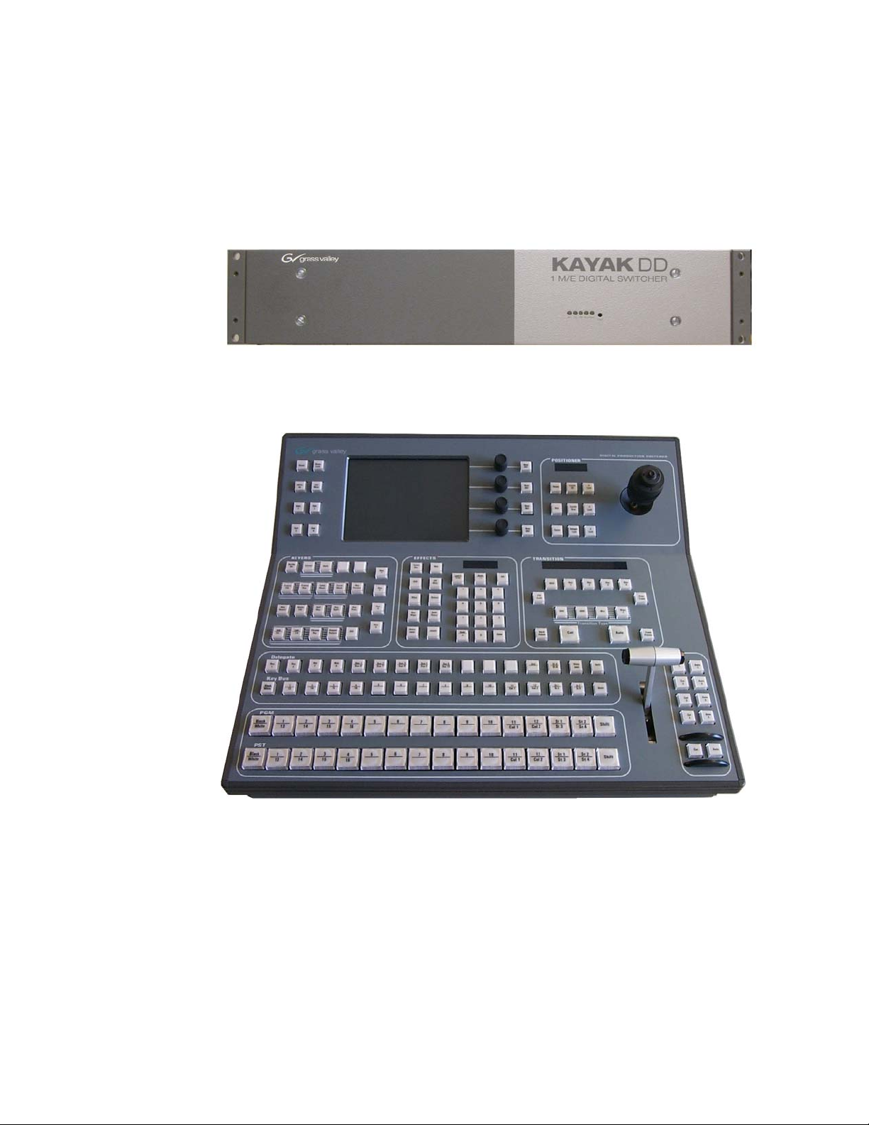
5.2 System Components
A KayakDD-1 Production Switcher system consists of a control panel with integrated
menu display (color TFT with touch-screen) and a Video Processor Frame with two
rack units (2RU) height.
Figure 1 Video Processor Fram e and Control Panel
Figure 2 Control Panel
26 Planning and Installation Manual
Page 28

5.3 Control Surface
KayakDD-1 Digital Production Switcher
Figure 3 KayakDD-1 Control Panel Surface
The panel is organized into subpanels that contain groups of related controls. The
panel provides real time button, knob, and lever arm control of one full function
mix/effects (PGM/PST with full M/E capability).
Connectors to the KayakDD-1 Video Processor frame and to other components of the
KayakDD-1 Control Surface are located on the rear of the panel.
Planning and Installation Manual 27
Page 29

KayakDD-1 Digital Production Switcher
5.4 Video Processor Frame
The KayakDD-1 Video Processor frame houses most of the system electronics in a
very compact design. A built-in fan system allows cooling of the frame. The frame
contains the following modules:
• Mainboard RY 3710
• M/E Processor Board RY 3720
• Power Supply Unit
• Fan Unit RC 3740
• Cable Set RC 3750
The figure below shows the frame with opened housing.
Fan
Air flow
M/E Processor Board
Power Supply Unit
Fan
Main Board
Figure 4 KayakDD-1 Video Processor Frame
The KayakDD-1 system has been designed for easy maintenance. There are no
serviceable parts inside. Modules and power supplies should be removed and
replaced from Thomson service personnel only.
28 Planning and Installation Manual
Page 30

5.4.1 System Components
The connectors for reference video, video, system control, etc. are located at the rear
of the Kayak Processor frame. The contains the following modules:
• Main Board RY 3710
• M/E Processor RY 3720
• Power Supply module
Redundant power supply is possible by connecting an external 48V power supply unit
(see order number in section 5.1.3). For example the KDD-PSU.
5.4.2 Video Processor Frame Options
Digital Picture Manipulators (iDPM)
The Kayak Digital Picture Manipulators per keyer provide the following internal digital
effects capability:
• 2-D effects in 3-D space with perspective (= 3D-planar),
• Border, outline, and extrude effects,
• Independent drop shadow, with the (KDD-DPM option which includes the KURL™
functionality)
• Glow and defocus effects, and Page turn,
• Splits, mirrors and slits.
RGB Color Correction
In addition to the standard solarization, posterization, mosaic capabilities and YUV
color correction, RGB color correction can be added to all M/E background, keyer fill,
and utility buses.
Chroma Keyers
In addition to the two standard chroma keyers, two more chroma keyers are added to
the system with the KDD-RGB option.
KayakDD-1 Digital Production Switcher
Planning and Installation Manual 29
Page 31

KayakDD-1 Digital Production Switcher
5.5 Functional Overview
5.5.1 Video Signal Flow
The basic system architecture (Figure 7) of the KayakDD-1 system has been designed
for operational flexibility. For example, all the outputs from the M/E are routed back to
the video crosspoint matrix, making all these signals accessible to the entire system.
The 16 video inputs to the Video Processor frame can be mapped to any of the 16
crosspoint buttons. Internally generated white and three backgrounds are also
available sources, as are the four RAM Recorder outputs. This source-to-button
mapping is done through the touch screen menu and can be stored as a user profile
for any number of individual users. Button mapping is the same on all buses.
The system has a full M/Es with PGM/PST. Internally generated black and two
backgrounds are also available sources, as are the four Still Store outputs.
The selected video on each bus is deserialized and reclocked before entering the
video processing circuitry. Video processing is available for each separate M/E
background, Key, and Utility bus, providing built-in solarization, posterization and
mosaic effects. In addition, contrast, brightness, and hue can be adjusted on a bus-bybus basis.
The M/E has four full-function keyers with optional internal Digital Picture Manipulators
effects. Each keyer has access to its own wipe generator as well as a pair of standard
floating chroma keyers which may be assigned to any keyers in the system. Two
complex wipe generators serve each M/E, providing a wide range of wipe choices with
modulation, rotation and multiplication of each one. Wipe signals can also be taken
from the Utility bus on the M/E.
The outputs from M/E Program and Preview are fed to dedicated BNCs and sent back
to the crosspoint circuitry for the Auxiliary buses as well as the clean feed output.
Ten Aux buses are available in the M/E system. The Aux bus outputs can be utilized in
a number of ways. Every Aux bus provides individually adjustable safe area and
crosshair (center cross) capability.
30 Planning and Installation Manual
Page 32

Input 1
Input 2
Input 3
Input 4
Input 5
Input 6
Input 7
Input 8
Input 9
Input 10
Input 11
Input 12
Input 13
Input 14
Input 15
Input 16
KAYAK 1M/E Switcher (Main Board)
XPTS
27 x 26
Single Mixer Effect (Plug In Board)
Video
Proc
Key Wipe Gen
4x Simple
Coplex
Wipe Gen
Aux
Proc
iDPM
KayakDD-1 Digital Production Switcher
Program A
Preview A
Mixer
Program B
Cleanfeed
Program B
Aux 1
Aux 2
Aux 3
Aux 4
Aux 5
Aux 6
Aux 7
Aux 8
Aux 9
Aux 10
RAM
Rec
BGD
Analog
525/625
Reference
Input
Gen
Sync
Gen
Control Processor
Figure 5 KayakDD Simplified Video Flow Diagram
5.5.2 System Control
KayakDD system control is designed for flexibility and simplicity. Ethernet, serial,
parallel, and USB are used for system component interconnections. Tally and GPI
control are available.
625: 420 frames = 16sec
525: 500 frames = 16sec
per Channel
Planning and Installation Manual 31
Page 33

KayakDD-1 Digital Production Switcher
32 Planning and Installation Manual
Page 34

6 Installation
This section describes the installation and setup of KayakDD-1 hardware.
6.1 Pre-Installation Procedures
Before you physically install the KayakDD-1 system, familiarize yourself with the tools
required, physical specifications, and safety and power requirements covered in this
section.
6.1.1 System Survey
Check all parts received against the packing list enclosed with your shipment, and
examine the equipment for any shipping damage. Immediately report any missing or
damaged items to the carrier and to your Thomson Grass Valley Service
Representative.
KayakDD-1 Digital Production Switcher
6.1.2 Line Voltage
KayakDD-1 components utilize auto-ranging power supplies which accommodate 100 240V. No switch settings are required, nor are any possible.
6.1.3 Safety Requirements
To prevent injury or equipment damage, read, understand, and follow all installation
safety precautions.
WARNING!
The Video Processor frame weighs approximately 6.5 kg (14.3 lb). Provide appropriate
equipment to support the frame during installation.
WARNING!
Electrical potential is still applied to some internal components even when power to the
frame is off. To prevent electrical shock when working on this equipment, disconnect
the AC line cords from the AC source before working on any internal components.
Residual voltage may be present immediately after unplugging the system; wait thirty
seconds to allow capacitors to discharge before working on the system.
CAUTION!
To avoid static damage to sensitive electronic devices, protect the KayakDD system
from static discharge. Avoid handling frame modules in a high static environment. Use
a grounding strap when handling modules, and touch the frame before you remove
any modules.
Planning and Installation Manual 33
Page 35

KayakDD-1 Digital Production Switcher
6.1.4 Installation Tasks
After completing the Pre-Installation procedures, the recommended installation tasks
given in this section are:
1. Unpack the equipment,
2. Install the KayakDD-1 Video Processor frame,
3. Install the KayakDD-1 control panel,
4. Connect all cables between KayakDD devices,
5. Connect cables to video inputs and outputs, and
6. Connect the power cables.
Power up and configuration, including setting IP addresses, is covered in detail in the
next sections of this manual.
34 Planning and Installation Manual
Page 36

6.2 Mounting the Processor Frame
6.2.1 Video Processor Frame Measurements
(19 inch)
(18.3 inch)
(3.5 inch)
(3 inch)
(3.44 inch)
(17.48 inch)
KayakDD-1 Digital Production Switcher
(15.94 inch)
(0.18 inch)
(16.67 inch)
Bold dimensions are [mm].
Figure 6 KayakDD-1 Video Processor Frame Dimensions
Planning and Installation Manual 35
Page 37

KayakDD-1 Digital Production Switcher
6.2.2 General Rack Mounting Instructions
• The maximum ambient temperature for this unit is 40°C (104°F).
• Installing the unit in a closed or multi-unit rack assembly, together with other units
could increase the maximum ambient for this unit.
• If the unit is installed in a rack, no ventilation openings should be blocked or
otherwise covered. Ensure a sufficient amount of airflow. Airflow through KayakDD
is from the left side of the frame to the right side of the frame.
• Mounting of the unit in the rack should be such that a hazardous condition is not
achieved due to uneven mechanical loading.
• When connecting the unit to the supply circuit be sure that the supply circuit of the
rack is not overloaded. For ratings see chapter Technical Specifications.
• The unit must be grounded to a good earth ground using a wire as specified by the
local electrical code. This wire is attached to the protective earth connector on the
rear.
• When connecting the unit in a closed or multi-unit rack assembly together with
other units be sure that the summation of the touch (leakage) currents for each
power supply circuit is not higher than 3.5mA. In this case the rack must be
permanently connected with an earth terminal. Earth connection is essential before
connecting supply voltage! For details see chapter Technical Specifications.
The video processor frame has to be mounted in a rack using the delivered screws.
For mobile application, using of slide rails are strongly recommended. For installation,
Thomson Grass Valley optionally provides a 19-inch cabinet with mounting
accessories. When using cabinets of other manufacturers, observe the respective
mounting instructions.
36 Planning and Installation Manual
Page 38
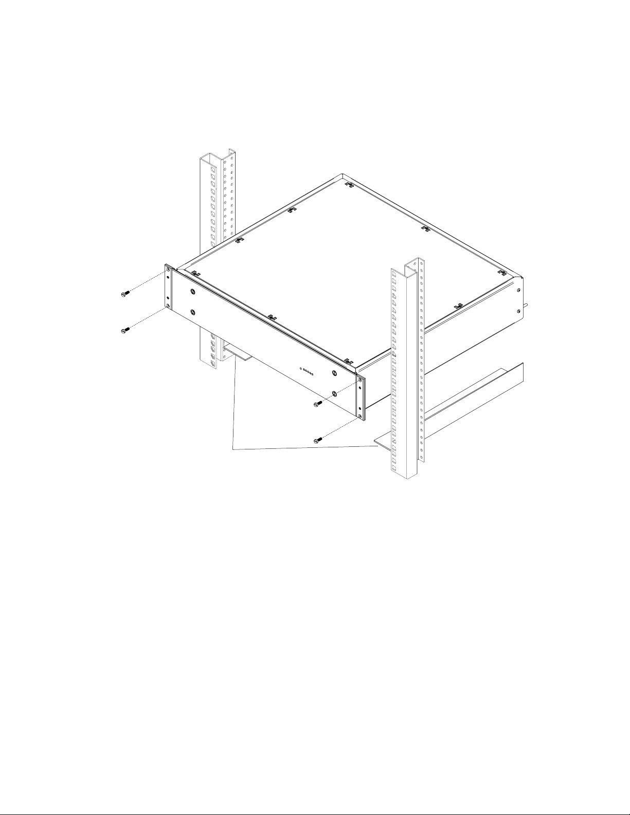
6.2.3 Rack Mounting Procedure
KayakDD-1 Digital Production Switcher
Slide rails
Recommended for mobil applications!
Not part of delivery!
Figure 7 KayakDD-1 Video Processor Frame Rack Mounting
• Place the right and left bottom ends of the KayakDD-1 on the slide rails, and slide
the equipment to the rear.
• Fix the rack angles of the video processor frame to the rack using the delivered
four screws.
WARNING!
For normal rack mounting the rack angle are strong enough. If the video processor
frame is fixed with at the rack angles only, do not load the frame with other equipment
or the cables. For mobile application (flight case, OB van), it is not allowed to fix the
video processor frame using the rack angles only!
Planning and Installation Manual 37
Page 39

KayakDD-1 Digital Production Switcher
6.3 Mounting the Control Panel
6.3.1 Control Panel Measurements
(16.46 inch)
(5.69 inch)
(10.23 inch)
(0.60 inch)
(2.55 inch)
(1.31 inch)
(3.19 inch)
(0.39 inch)
(15.66 inch)(0.40 inch)
Bold dimensions are [mm]
Figure 8 KayakDD-1 Control Panel Measurements 1 of 2
38 Planning and Installation Manual
Page 40

KayakDD-1 Digital Production Switcher
(0.39 inch)
(16.46 inch)
(16.85 inch)
(17.64 inch)
(0.39 inch)
(17.64 inch)
Bold dimensions are [mm]
Figure 9 KayakDD-1 Control Panel Measurements 2 of 2
Planning and Installation Manual 39
Page 41

KayakDD-1 Digital Production Switcher
6.3.2 Table Top Mounting
In many cases the panel can just be put on a table. Gummed feet prevent accidental
movement of the panel.
6.3.3 Cut Out Dimensions for Surface Mounting
For surface mounting of the control panel the cutout dimensions are:
400 mm x 430 mm
CAUTION!
Regardless of mounting method or cutout dimensions, ensure that there is at least
2 inch (50 mm) of clear space at the rear of the panel below the mounting surface for
proper cable clearance and air flow.
6.3.4 Mounting Holes for Panel Fastening
For fastening the panel in a table there are four M4 thread drillings on the panel. Those
allow to fasten the panel from below the table. The length of the screws is dependent
on the respective thickness of the tabletop (see Figure 9 and 10 with mounting details
below).
The figure below shows the position of the mounting holes.
Four thread drillings
for panel fastening
Figure 10 Bottom View, Position of the Mounting Points
40 Planning and Installation Manual
Page 42

(2.95 inch)
Thread drillings
for panel fastening
(10.55 inch)
M4 thread drilling
KayakDD-1 Digital Production Switcher
(17.24 inch)
(0.2 inch)
Bold dimensions are [mm]
Figure 11 Bottom View, Measurements of the Mounting Points
Washer
Lock nut
Fastening screw
Panel Fastening Procedure:
The length of the screw is dependent on the
thickness of the tabletop! The M4 screw
should be approx. 25 mm of (1 inch) longer
than the thickness of the tabletops.
Screw lock nut completely on the fastening
screw and put on a washer.
Then turn the fastening screw from below
through the drillings in the table in the
thread drillings of the frame.
At least turn the locking nut up to fix the
panel.
Figure 12 Panel Fastening Procedure
Planning and Installation Manual 41
Page 43

KayakDD-1 Digital Production Switcher
6.4 Control Panel Connectors
Figure 13 Control Panel Connectors
The rear of the KayakDD-1 Panel provides the power and system control connectors
for the system:
Jack Designation Note
J1 DC POWER IN
M4 threaded pin
J2
USB 1
J3
USB 2
J4 LAN
DC power input connector for 48V operating voltage.
Connecting with the DC POWER OUT at the Processor
Frame. An interconnecting cable with a length of 10 m
(32ft.) is enclosed.
Alternatively optional cables of 50m (164 ft) and 100m (328
ft.) length can be used.
In case of longer distances (e.g. using fiberoptic cabling
(not supplied by Thomson Broadcast & Media Solutions) )
a separate 48V Power Supply Unit has to be connected.
Note:
The external power supply unit must comply with the
SELV (Safety Extra Low Voltage) standard exclusively.
ELV and TNV standard is not permitted!
Screw terminal for additional unit earthing
Connectors for USB devices, e.g. CD-ROM Drive, Mouse,
Keyboard or Memory Stick (only via USB 2).
Only recommended devices are supported.
For recommended Memory Stick refer to chapter 7.2.1
below.
Function of other devices can not be guaranteed.
RJ45 connector for connection to the Processor Frame.
An crossed interconnecting cable with a length of 20 m is
enclosed. Cables with lengths of 20m or 50m can be
ordered optionally.
42 Planning and Installation Manual
Page 44

KayakDD-1 Digital Production Switcher
Jack Designation Note
J5 RS 485
RS422/RS485 interface for connecting an external
devices. The software control automatically switches
over the interface to master or slave (bus
control/tributary), depending on which unit driver has
been selected in the menu.
J6 RS 232
RS232 interface for connecting a diagnosis computer
or other external devices.
Additional connectors at the rear of the menu display.
These connectors are operator accessible!
Jack Designation Note
USB 3, 4
Connectors for USB devices, e.g. CD-ROM Drive,
Mouse, Keyboard or Memory Stick . (only via USB 4)
Only recommended devices are supported.
For recommended Memory Stick refer to chapter
7.2.1 below.
P/S 2
Possibility to connect a P/S 2 Mouse or Keyboard.
Planning and Installation Manual 43
Page 45

KayakDD-1 Digital Production Switcher
6.5 Processor Frame Connectors
AC POWER IN
100 - 240 V
max. 4A
50/60 Hz
Caution: For continued protection against risk
of fire, repplace only with same type and rating of fuse.
J1
grass valley
PGM-A CLEANPVW-A CLEAN-PVW AUX 1 AUX 2 AUX 3 AUX 4 AUX 5 AUX 6 AUX 7 AUX 8 AUX 9 AUX 10
J 4 J 5 J 6 J 7 J 8
2*T6,3A /H
250V
IN 2
IN 1
IN 3
J 26
J 25
J 27
KAYAK
1 M/E DIGITAL SWITCHER
J 9 J 10 J 11 J 12 J 13 J 14 J 15 J 16 J 17 J 18
IN 4
IN 6
IN 5
J 28
J 30
J 29
This device complies with part 15 of the FCC Rules. Operation is subject to the following two conditions:
DD
(1) This device may not cause harmful interference, and
(2) this device must accept any interference received, including interference that may cause undesired operation.
IN 8
IN 7
IN 9
J 32
J 31
J 33
INPUT
IN 10
IN 11
J 34
J 35
Figure 14 Video Processor Frame Connectors
Jack Designation Note
J1 AC POWER IN
AC POWER IN
INPUTS
J25
IN1 – IN16
:
J40
M/E OUTPUTS
J4/J5
PGM-A
J6
PVW-A
J7
PGM-B
J8
PVW-B
J9
AUX 1 – AUX10
:
J18
AUXM/E
IN 12
IN 14
IN 16
IN 13
J 36
IN 15
J 38
J 40
J 37
J 39
Port 1 Port 2 Port 3
Port 4 Port 5 Port 6
ANALOG
J 42
J 41
REFERENCE
J2 J3
J 19 J 20 J 21
J 22 J 24J 23
RS 485
GPI/O - Tally
+
-
48V / 5A max.
DC POWER
IN OUT
-
48V / 1,6A
N4067
LAN
R
Listed
Prof. Vid. Equipm.
3S13
J 44J 43
+
Mains connector (IEC-320, CEE-22) for power supply
to the Video Processor Frame.
Operating Voltage: 100V-240V AC +/-10% auto-range
Caution!
Double-pole or neutral fusing.
After operation of the protective device, parts of
the equipment that remain under voltage might
represent a hazard during servicing.
Caution!
For continued protection against risk of fire,
replace only with same type and rating of fuse!
2x 6.25A /T 250
Frame power switch
BNC / Serial Comp (ITU-R 656) video inputs
BNC / Serial Comp (ITU-R 656)
Double Program output, A channel
Preview output, A channel
Program output, B channel
Preview output, B channel
Auxiliary Outputs, BNC / Serial Comp (ITU-R 656)
44 Planning and Installation Manual
Page 46

KayakDD-1 Digital Production Switcher
Jack Designation Note
J41
REFERENCE
J42
Reference input, BNC / 75 ohms
Loop through sync input for analog Blackburst or
CCVS signal.
J19
RS 485 PORTS
:
J24
J43 GPI/O - TALLY
Six control ports, 9-pin D-type female
RS485 serial ports for devices such as DVEs, Editors,
Routers and for Machine Control (Disk Servers, VTR).
50-pin D-type female
General-purpose interface connector with 8 input
channels and 32 output channels.
The connector is used for Tally also.
Refer table below for respective pin assignment.
J44 LAN
RJ45 connector for connection to the Control Panel.
An interconnecting cable with a length of 10 m is
enclosed. Cables with lenghs of 20m or 50m can be
ordered optionally.
J2 DC POWER IN
Input connector for external DC Power Supply for
redundancy (High current D-Sub, female).
Input voltage: 48V/ 5A
Note:
The external power supply unit must comply with
the SELV (Safety Extra Low Voltage) standard
exclusively. ELV and TNV standard is not
permitted!
Additionally the 8V DC voltage for RAM Recorder
buffering can be supplied via this socket.
Refer table below for respective pin assignment.
J3
DC POWER
OUT
Output connector for Panel DC Power Supply.
(High current D-Sub, male).
Output voltage: 48V/ 3A
An DC power interconnecting cable with a length of
10 m is enclosed.
Planning and Installation Manual 45
Page 47

KayakDD-1 Digital Production Switcher
6.6 Pin Assignments
6.6.1 RS 485 Port
Socket Pin Bus Controller Tributary
D-9 Female
Pin 1Pin 5
Pin 6Pin 9
1 Chassis Ground Chassis Ground
2
3 TxB (+) RxB (+)
4 Signal Ground Signal Ground
5 Not used Not used
6 Signal Ground Signal Ground
7 RxB (+) TxB (+)
8
9 Chassis Ground Chassis Ground
RxA (−) TxA (−)
TxA (−) RxA (−)
6.6.2 RS 232 Port
Socket Pin Signal
D-9 Female
Pin 1Pin 5
Pin 6Pin 9
1 Chassis Ground
2 Transmit Data
3 Receive Data
4 Not used
5 Signal Ground
6 Not used
7 Clear to Send
8 Request to Send
9 Not used
46 Planning and Installation Manual
Page 48
6.6.3 Panel DC Power In
Socket Pin Signal
D-Sub Male
Pin A1
6.6.4 Frame DC Power In
Socket Pin Signal
D-Sub Male
Pin A1
Pin 2Pin 1
Pin 5Pin 3
Pin 2Pin 1
Pin 5Pin 3
Pin A2
Pin A2
KayakDD-1 Digital Production Switcher
A1 48 V (+)
A2
48 V (−)
1 2 3 4 -
5 -
A1 48 V (+)
A2
48 V (−)
1 Ground
2 Return Sense
3 + 7 V (RAM Rec)
4 -
5 48V Return
*
Note: Pins 2 and 5 must be connected in the plug
of the external power supply unit.
*
*
6.6.5 Frame DC Power Out
Socket Pin Signal
D-Sub Female
Pin 1Pin 2
Pin A2
Pin 3Pin 5
Pin A1
Planning and Installation Manual 47
A1 48 V (+)
A2
48 V (−)
1 2 3 4 -
5 -
Page 49

KayakDD-1 Digital Production Switcher
6.6.6 Frame GPI/O – Tally
Socket Ribbon Cable 50-Pin D-Sub Signal
D-50 Female
Pin 18
Pin 1
Pin 34
Pin 33
Pin 17
Pin 50
1 1 GPIInCom
2 34 GPIInCom
3 18 GPIIn1
4 2 GPIIn2
5 35 GPIIn3
6 19 GPIIn4
7 3 GPIIn5
8 36 GPIIn6
9 20 GPIIn7
10 4 GPIIn8
11 37 GPIOutComA
12 21 GPIOut1A
13 5 GPIOut2A
14 38 GPIOut3A
15 22 GPIOut4A
16 6 GPIOutComB
17 39 GPIOut5B
18 23 GPIOut6B
19 7 GPIOut7B
20 40 GPIOut8B
21 24 GPIOutComC
22 8 GPIOut9C
23 41 GPIOut10C
24 25 GPIOut11C
25 9 GPIOut12C
26 42 GPIOutComD
27 26 GPIOut13D
28 10 GPIOut14D
29 43 GPIOut15D
30 27 GPIOut16D
31 11 GPIOutComE
32 44 GPIOut17E
33 28 GPIOut18E
34 12 GPIOut19E
35 45 GPIOut20E
36 29 GPIOutComF
37 13 GPIOut21F
38 46 GPIOut22F
39 30 GPIOut23F
40 14 GPIOut24F
41 47 GPIOutComG
42 31 GPIOut25G
43 15 GPIOut26G
44 48 GPIOut27G
45 32 GPIOut28G
46 16 GPIOutComH
47 49 GPIOut29H
48 33 GPIOut30H
49 17 GPIOut31H
50
50 GPIOut32H
48 Planning and Installation Manual
Page 50

6.7 Cabling and Control
6.7.1 Cabling
The cabling of a standard KayakDD-1 application is illustrated in figure below.
Keyboard
USBP/S 2
3
4
Mouse
KayakDD-1 Digital Production Switcher
Note:
Keyboard and Mouse not
mandatory and not supplied.
Control Panel
DC Power Supply
48V
CAT5 Crossover Cable
alternatively
Video Processor Frame
REFERENCE
Supplied DC interconnection cable
AC Power Supply
110-240V
DC Power Supply
48V (Redundancy)
Note: The KDD-PSU Power Supply Unit for redundancy contains only one DC cable (5 m).
Additional cables must be ordered separately!
Figure 15 KayakDD-1 Standard Cabling
Planning and Installation Manual 49
Page 51

KayakDD-1 Digital Production Switcher
6.7.2 Control Cabling
A simple KayakDD-1 system consisting of a Control Panel and Video Processor frame
uses point-to-point connections and does not require connection to an external
Ethernet Local Area Network (LAN).
The KayakDD-1 system uses Ethernet, serial, parallel, and USB connections.
Tally and GPI/O control are also available.
6.7.2.1 Mouse and Keyboard Connection
A standard PS/2 mouse and keyboard can be installed to the rear of the control panel
if desired (see figure above). Be sure to power down before installing either the mouse
or keyboard.
6.7.2.2 LAN Cable Polarity
The point-to-point connections between the Control Panel and the Video Processor
frame, require that the Transmit (TX) and Receive (RX) pairs in the Ethernet cables be
swapped. This is normally achieved with a special peer-to-peer (crossover) LAN cable
or an Uplink port on the switch or hub.
NOTE!
The LAN cable supplied with the KayakDD system is a cross-wire cable!
If no communication can be established (either LAN Link LED is off), a possible cause
may be incorrect cable polarity.
6.7.2.3 LAN Requirements
A simple KayakDD system uses point-to-point connections and does not require an
external Ethernet Local Area Network (LAN).
A KayakDD system requires a LAN when components in addition to a Control Panel,
and Video Processor frame are connected or when external network access to a file
system is desired. An appropriately sized Ethernet switch will be required.
CAUTION!
Ethernet hub or switch are necessary to exceed maximum cable runs. An existing
facility Ethernet switch (not hub) can support KayakDD if an adequate number of ports
are available. Keep your facility network and technical network separate in order to
avoid network traffic negatively affecting KayakDD system operation.
Refer to table below for Ethernet specifications.
50 Planning and Installation Manual
Page 52

KayakDD-1 Digital Production Switcher
NOTE! All Ethernet components must be supplied by the customer.
Ethernet Specifications
Cables
Type
10Base-T and 100Base-T compatible.
Category 5 cable, 8 conductor twisted pair.
The system will work at 10Base-T with reduced
performance. 100Base-T components are highly
recommended.
Connectors
Length
RJ-45 male connector at each end of cable.
10Base-T: 984 ft (300 m) maximum.
100Base-T: 328 ft (100 m) maximum.
Use a switch when necessary to exceed maximum
cable runs.
Switch
Speed
Ports
Dual: 10 and 100 Mb
RJ-45 auto-negotiating 10/100 Mb; number of
ports required is dependent upon system size.
Unmanaged
Recommended. Configuration not required, but do
not provide remote monitoring capability.
Managed
May be used. Require configuration, but offer
remote monitoring capability.
6.7.2.4 Ethernet Switches and Hubs
KayakDD optional components rely primarily on Ethernet switches for LAN
interconnects. A hub is required only if there is a need to exceed 328 ft (100 m)
between a Control Panel and Video Processor frame. If a hub is used, connect the hub
to the switch via the Uplink port, or through a peer-to-peer crossover cable.
6.7.2.5 Factory Settings
The default factory setting for the IP address is
• 192.168.0.70 for the video processor frame
• 192.168.0.73 for the control panel
The Device Setup menu allows to change the IP address. It is only allowed to change
the last octet of the IP address (to accommodate several KayakDDs on the same
network).
IMPORTANT NOTE!
In order to integrate KayakDD devices into an existing network, ask the local
network administrator for the subnet mask of the network. Before changing IP
addresses always set the subnet masks of the KayakDD devices to the mask of
the local network. If all changes are made and a frame is not visible to the panel,
press ‘Rescan’ in the “Device Control” menu of the panel.
Planning and Installation Manual 51
Page 53

KayakDD-1 Digital Production Switcher
6.7.3 Video
Different video and control wiring configurations may be used to meet individual facility
requirements. All KayakDD system video inputs and AUX outputs are configurable. For
cabling configuration flexibility, each input can be mapped to any KayakDD panel
source select button, and any KayakDD system video signal can be mapped to any
AUX output connectors.
Program and Preview bus outputs for the M/E have dedicated output connectors as
well.
6.7.3.1 Inputs
Physical inputs are the actual BNC connectors that feed a signal into KayakDD. These
non-looping inputs on the back of the Video Processor frame are numbered 1 through
16. Each receives a 270 MHz serial digital video
signal. All video inputs are software configurable, and each input can be mapped to
any KayakDD panel source select button.
6.7.3.2 Outputs
The KayakDD frame provides dedicated program and preview video output connectors
for the M/E. The main program output signal is available on two BNC connectors. All
other outputs are available on one BNC connector only.
Any KayakDD video source can be routed to any Aux bus output (1 through 10).
6.7.3.3 Reference Input
The looping reference input accepts analog 525 or 625 composite video. Burst is not
required, but typically facility reference color black is used. The timing of all switcher
inputs and outputs are referenced to this signal. KayakDD can auto-sense whether the
reference is 525 or 625 and can change the internal standard accordingly.
52 Planning and Installation Manual
Page 54

6.7.4 Video Timing and Delay
The total delay of a video input to the switcher output can vary according to the
relationship of the input to the switcher reference. The switcher will automatically
autotime inputs by a specified amount (± B µs). Inputs must be within this timing range
to be properly timed at the output. A timing diagram for illustrating the input autotiming
window and various switcher delay values is provided in figure below.
KayakDD-1 Digital Production Switcher
Figure 16 Timing and Delay
NOTE!
For both 525 and 625 switcher operation, the approximate maximum switcher delay is
one line of video. Exception is the use of a Digital Picture Manipulators. The signal
going through the Digital Picture Manipulators is delayed by one frame.
• For inputs entering the switcher in zero time with the reference, the total delay
through the switcher is expressed as the Nominal Switcher Delay
(A µs).
• Inputs that reach the switcher at the latest point in the autotiming window
(+ B µs) will have a total delay that equals the length of switcher processing. This
value is expressed as the Minimum Switcher Delay (C µs).
• Inputs that reach the switcher at the earliest point in the autotiming window will
have a total delay equal to the Nominal Switcher Delay (A µs) plus the autotiming
value (– B µs). This value is expressed by the Maximum Switcher Delay value (D
µs).
Delay values for a KayakDD system are given in table below
System Video Delay Values
Typical Switcher Delay
Auto-timing Range
Minimum Switcher Delay
Maximum Switcher Delay
A
B
C
D
36 µs
53 µs
10 µs
63 µs
Planning and Installation Manual 53
Page 55
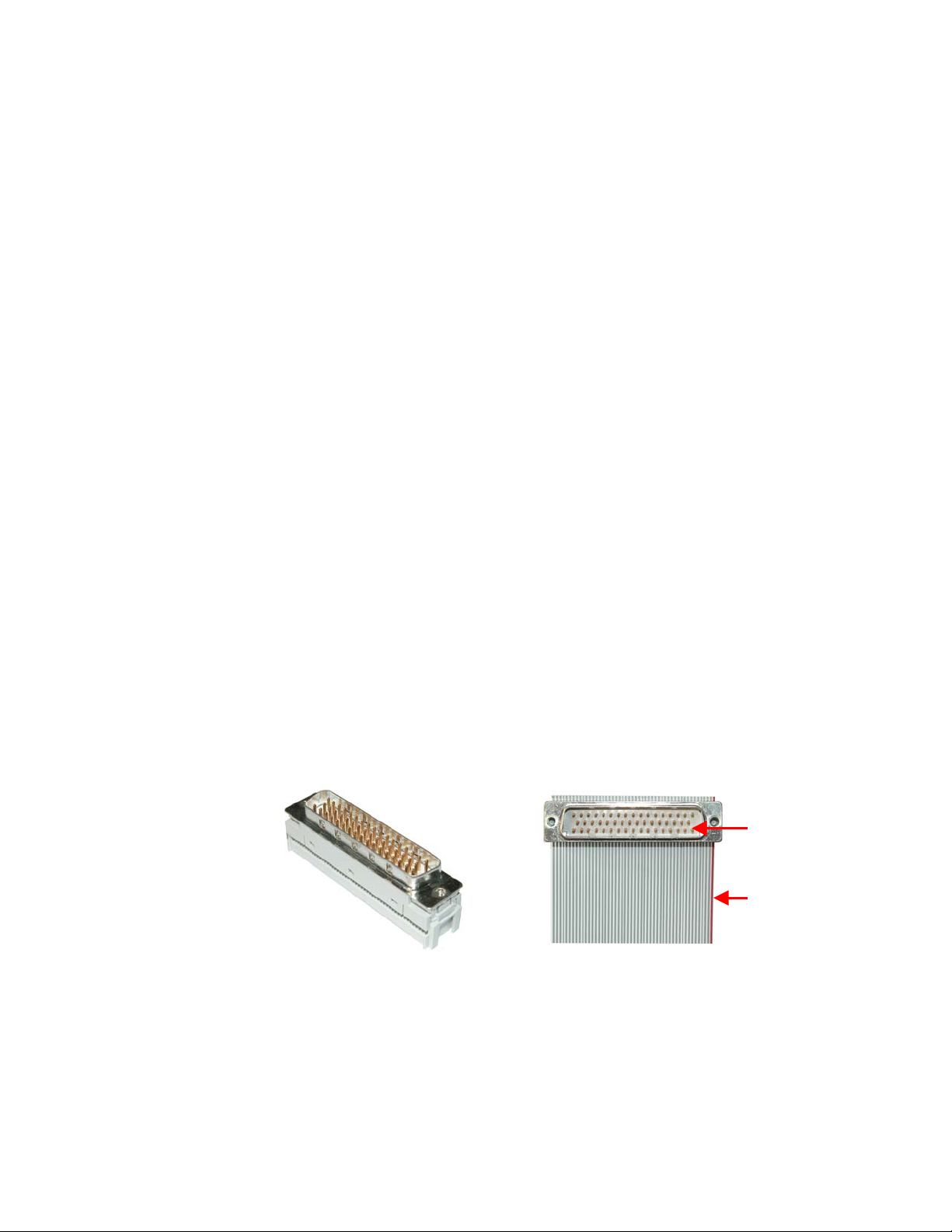
KayakDD-1 Digital Production Switcher
6.7.5 GPI / Tally Outputs
The KayakDD GPI / Tally system has 32 universal relays that interface source tally and
GPI Output information to an external system through the Tally Port connector, J43.
The channels can be assigned in the Setup menu.
Tallies are a source attribute and relays are automatically assigned to a source when
source definitions are defined in the Setup menu during initial system configuration.
The nominal rating specification for each relay is 2 A, 30 V.
6.7.6 GPI Inputs
A simple connection between the two connectors activates the corresponding input.
This kind of control is suitable for a connection to a relay contact or to an opencollector output.
ATTENTION!
When connecting to an open-collector output, there is no ground potential isolation
between the Video Processor frame and controlling devices. The internal optocouplers are supplied separate (galvanically insulated) voltage (12V fan supply).
Since the circuit ground is led out of the device, the cabling has to be shielded for this
kind of control. Non-shielded cables may cause EMC and/or ESD problems!
6.7.7 Tally Adapter
A 50pin male sub-d connector (the counterpart of the Frame-Tally connector) is part of
the delivered accessories. Please purchased a 50pol ribbon cable with desired length
and mount the connector by pressing with a recommended tool.
Figure 17 Tally Adapter Cable
Pin 1
Pin 1 of the
ribbon cable
54 Planning and Installation Manual
Page 56

KayakDD-1 Digital Production Switcher
7 Service Instructions
7.1 Running Panel Tests
For faster checking the function of the KayakDD Control Panels, a series of test
procedures are available which can be called by simply pressing the button.
For selecting the tests, simultaneously press the buttons
BlackPreset + Trans Preview + BGD (or Key 1 ... Key 4)
in the TRANSITION control panel.
Figure 18 KayakDD Control Panel Detail – Transition Panel
Planning and Installation Manual 55
Page 57

KayakDD-1 Digital Production Switcher
7.1.1 Local Panel Test Mode 1 (Button Test)
Button combination: Black Preset + Trans Preview + BDG
In this test mode, the logical address of the pressed button appears in the display.
7.1.2 Local Panel Test Mode 2 (LED Test)
Button combination: Black Preset + Trans Preview + Key1
In this mode, the lamp of the pressed button is lit. The underfloor LEDs will be
switched on and off with the neighbouring bright button.
Special test buttons:
BGD, Key1 - Key4 → Switch “On” underfloor LEDs on
Shift, Make (PGM+PST+Delegation) → Switch “Uncal” underfloor LEDs on
Key1 Cut / Key4 Cut → Switch the arrow (Fader) on
7.1.3 Local Panel Test Mode 3 (Group Test / On Air Highlight Test):
Button combination: Black Preset + Trans Preview + Key2
In this mode, whole button groups are switched on and off by pressing any button in
the group. In the key bus, program and preset can be also switched between white and
red.
7.1.4 Local Panel Test Mode 4 (Connect Mode)
Button combination: Black Preset + Trans Preview + Key3
This is no test mode, but a possibility to be connected to a mainframe without using
sidepanel. Simply enter the last byte of the IP address and confirm with <Return>.
Afterwards leave the test mode with Black Preset + Trans Preview + Key3, and then
one can control the mainframe.
56 Planning and Installation Manual
Page 58

7.1.5 Local Panel Test Mode 5 (Colour Test)
Button combination: Black Preset + Trans Preview + Key4
In this mode select a key group on the number block, and then select with the buttons
Key1-4 the different colours (Key1 = white, Key2 = red, Key3 = green, Key4 = blue).
The most groups have only white LEDs, the four bus rows are white and red and the
number block has all four colours.
Press the following transition buttons to change the brightness:
DVE → Dark in large steps
ADD → Dark in small steps
Mix → Bright in small steps
Wipe → Bright in large steps
KayakDD-1 Digital Production Switcher
Planning and Installation Manual 57
Page 59

KayakDD-1 Digital Production Switcher
7.2 Software-Update
7.2.1 Recommended Memory Sticks
For KayakDD software instalation a USB Memory Stick is necessary. At the time the
following types are approved:
• APACER Flash Drive (HandySteno) 256MB (USB1.1)
• APACER Flash Drive (HandySteno) 256MB (USB2.0)¹
• APACER Flash Drive 128MB (USB1.1)¹
• APACER Handy Steno HT202 USB 2.0 Flash Drive 128MB
http://www.apacer.com/apacer_english/product_html/handy_steno11.asp
• TRANSCEND JetFlash Type TS256MJFLASHA (USB2.0)
http://www.transcend.com.tw http://www.transcendusa.com
• MEMOREX Thumb Drive USB 256 MB
http://www.memorex.com/products
• SanDisk Cruzer Mini 256MB, SanDisk Cruzer Mini 128MB
http://www.sandisk.com/consumer/cruzermini.asp
• Twinmos Mobile DiskIII 128MB
http://www.twinmos.com
• PQI Corp.: Intelligent Stick 1GB, CoolDrive 512MB, CoolDrive 1GB
http://www.pqi1st.com/products/istick.asp
1
2
7.2.2 Preparing the USB Memory Stick
• Plug an USB memory stick into a standard PC or laptop
• Insert the installation CD ROM (DS0205.xxx)
• Open the USBSetup directory
1
Cable adapter needed for KayakDD USB 4 slot
2
USB Setup does not detect this devise as removable device
58 Planning and Installation Manual
Page 60

KayakDD-1 Digital Production Switcher
• Start the setup.exe installation program
• Press the Next button inside the Welcome window
• The installation program scans the system for removable devices to determine
the destination folder
• If the proposed folder doesn't match your USB installation device, choose
another folder by using the Browse menu
• Press Next to get into the Component Information window
Planning and Installation Manual 59
Page 61

KayakDD-1 Digital Production Switcher
• Select the version you want to install on your USB device - it is possible to select
more than one version
• Press Next to get an overview of selected components
• Press Next to start the installation
IMPORTANT NOTE!
It is recommended to install the USB memory stick directly from the original CD
ROM. Never delete or change files on an successfully installed USB memory
stick, otherwise the KayakDD software installation process will fail (checksum
error after 99 percent of the installation process is completed).
NOTE!
On KayakDD control panel use the USB ports 2 and 4 - ports 1 and 3 are not
supported!
60 Planning and Installation Manual
Page 62

KayakDD-1 Digital Production Switcher
• Plug-in the memory stick in the control panel's USB 2 or USB 4 slot. In case that
your stick doesn't fit (mechanically) in USB4 slot, please use the enclosed
extension cable as adapter.
If the control panel software has recognized a valid Kayak release version on the
memory stick, the Device Control menu is called automatically.
Figure 19 Device Control Menu
The Device Control menu shows all in the network connected devices (Kayak-MF =
Mainframe, Kayak-CP = Control Panel) with IP address and software version installed.
Planning and Installation Manual 61
Page 63

KayakDD-1 Digital Production Switcher
7.2.3 Software Loading/Update
• Select the respective device in the menu list.
• Menu Software Update appears
• Push button Start Install.
• The correct software will be installed in the respective device
(MF or CP) automatically.
NOTE!:
Two partitions are availably in the flash for the application software. With "Start Install"
the empty or a partition which is older as the active partition (recommended) will be
updated. With "Install Part. X” the current active software will be updated.
Figure 20 Device Control Menu with Software Update Dialog
62 Planning and Installation Manual
Page 64
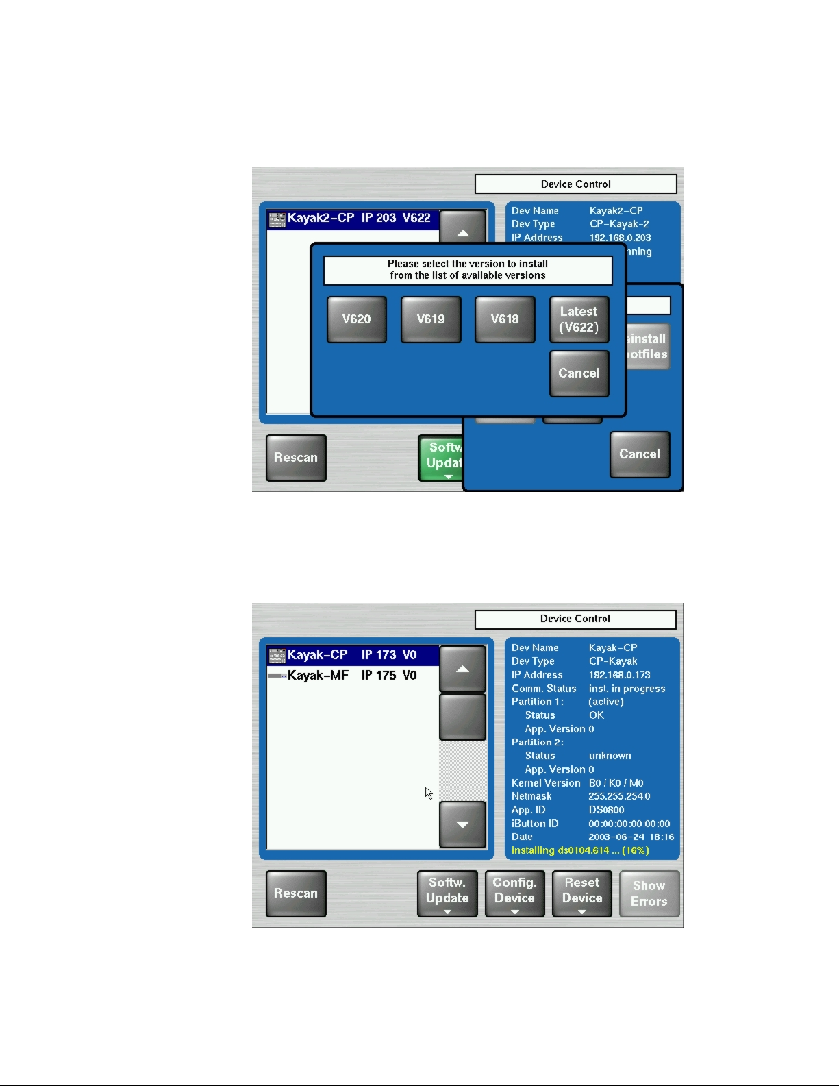
7.2.4 Installation Procedure
KayakDD-1 Digital Production Switcher
Figure 21 Start Installation Procedure
• After pressing the Start Install button the available versions are shown. Select
the version to install. The installation procedure starts.
• The progress of the installation procedu re is displayed in percent.
The currently installed file (file name) is shown as well.
Figure 22 Installation Procedure
Planning and Installation Manual 63
Page 65

KayakDD-1 Digital Production Switcher
• The Installation Procedure can be cancelled by using the button Abort Install in
the menu Software Update.
Figure 23 Cancel Installation Procedure
• After canceling the installation, the Status "inst. failed" is displayed.
• The respective partition can not be used and not be activated.
Figure 24 Device Control Installation Status
64 Planning and Installation Manual
Page 66

KayakDD-1 Digital Production Switcher
• When running software version V650 or later, a CPLD firmware update process is
appended: after all files have been copied and verified the system checks whether
an CPLD update is necessary or not. The CPLD updating process is described in
chapter 7.2.5. If no update if necessary the installation procedure is finished.
• After finishing the installation procedure, the system ask “Do you want to reset
the device now?” The installed software is availably after a restart only!
Figure 25 Finish Installation
IMPORTANT NOTE!
• Do not cancel the installation by switching off the devices!
• Do not pull out the memory stick during the installation procedure!
• Cancel the installation with the Abort Install button only!
• Perform a reset after each device software upgrade
• Verify that the active partition shows the new software version
(e.g. V6.2.2.8).
Planning and Installation Manual 65
Page 67

KayakDD-1 Digital Production Switcher
7.2.5 Updating the CPLD Firmware
At the end of each installation process the system checks whether an CPLD update is
necessary. This is done by comparing the versions of the installed CPLD firmware files
on flash with the current CPLD version tags stored within an EEPROM of each
hardware board. If the version of at least one file is newer an update of the CPLD is
necessary and the user is notified.
Figure 26 CPLD Update
To skip the CPLD update press No, to confirm the update press the Yes button
(recommended). After the user has confirmed the update, the device will be restarted.
During this sequence the CPLD will be updated. The progress of the update procedure
is displayed in percent within the Device Control menu. The currently installed file (file
name) is shown as well.
Don’t change to a menu other than the Device Control menu after initiating an
CPLD update on a Kayak mainframe! Otherwise the update process can’t be
monitored.
CAUTION!
Do NOT switch off the device while the CPLD update is running – monitored by
red progress indication. Otherwise the device will be permanently damaged!
After the CPLD update is finished the system has to be restarted. This brings the
device to normal operation mode.
If the installation process is terminated from the system refer to the Trouble Shooting
section 7.4.5 of the manual.
66 Planning and Installation Manual
Page 68

7.3 Device Configuration
7.3.1 Configure Device Menu
With the menu "Configure Device" the following configuration data of a device can be
changed:
• The date and time of the selected device (Set Date)
• The date and time of all connected devices (Set all Data)
• IP Address of the selected device (Set IP Addr)
• Net mask of the selected device (Set Netmask)
Important Remark:
This function should be used by a qualified network administrators only.
Different netmasks for MF and CP lead to limited communication between
the net devices.
• Logical device name ("Set Name”). Default Kayak-MF or Kayak-CP, the name is
can be defined by the user.
KayakDD-1 Digital Production Switcher
Figure 27 Configure Devices
Planning and Installation Manual 67
Page 69

KayakDD-1 Digital Production Switcher
7.3.2 Reset / Check / Clear Device Menu
The menu „Reset/Check/Clear Device“ should only be used by qualified users!
The following functions can be configured:
• Start/Restart the device (Reset DEVICE)
• Re-initialize the RAM disk area on the flash (RAM disk Clear)
• Re-initialize the Application disk area on the flash (Clear AppDisk)
• Deleting the Application State (Clear AppState)
• Deleting the Operational State (Clear OpState)
• Re-initialize the State Memory Partition (Clear StateMem)
• File system check of four flash partitions (Check" Flashx)
Figure 28 Reset/Clear/Check Devices Menu
68 Planning and Installation Manual
Page 70

7.4 Trouble Shooting
7.4.1 How to Calibrate the TouchScreen
In order to arrive the menu „Touchscreen Calibration“, go the following path:
Home / Install / Touchscreen Calibration / Start Calibr.
or use the following shortcut:
and follow the instructions on the display.
7.4.2 Lost LAN Connection
Connect to a mainframe (in case the panel lost the IP address and therefore does not
connect automatically
Proceed as follows:
• Press the following buttons together in TRANSITION subpanel:
Black Preset + Trans PVW + Key3,
this switches the EFFECTS subpanel into address entry mode,
• Type in the last group of the mainframe IP address (example, if the address is
"192.168.0.70" type in "70") and press ENTER.
• The panel will 'load systemfiles' etc. i.e. connect to the mainframe.
KayakDD-1 Digital Production Switcher
Menu Lock + User 3
7.4.3 Problems with Network Configuration
When an IP address of a KayakDD frame has been changed in order to integrate the
devices into an existing network and the subnet mask of the device does not fit to the
mask of the network, the connection between frame and panel will be lost.
In this case establish a serial terminal connection to the frame and replace the IP
address. This should be done by qualified service personnel only!
Type the following command into the terminal shell:
sysIPAddressSet “<old IP address>”
example: sysIPAddressSet “192.168.0.71”
After pressing ‘Rescan’ in the Device Control menu of the panel, the frame should be
visible again. If ‘Rescan’ doesn’t help, reboot frame and panel.
Planning and Installation Manual 69
Page 71

KayakDD-1 Digital Production Switcher
IMPORTANT NOTE!
In order to integrate KayakDD devices into an existing network, ask the local
network administrator for the subnet mask of the network. Before changing IP
addresses always set the subnet masks of the KayakDD devices to the mask of
the local network. If all changes are made and a frame is not visible to the panel,
press ‘Rescan’ in the “Device Control” menu of the panel.
Network configuration defaults:
• IP address frame: 192.16 8.0.70
• Subnet Mask frame: 255.255.255.0
• IP address p anel: 192.168.0.73
• Subnet Mask panel: 255.255.255.0
70 Planning and Installation Manual
Page 72

7.4.4 How to Connect a PC / Laptop to the KayakDD
First the following things are needed:
• Laptop / PC
• Hub / Switch
• 3 x Twisted Pair Network Cable (1:1)
Connect the KayakDD Panel, Frame and the PC / Laptop like as the following picture:
KayakDD-1 Digital Production Switcher
Figure 29 PC Connection
7.4.4.1 Network Properties Windows 2000/XP
Right click on “My Network Places”, choose Properties.
Configuration:
• Right click on “Local Area Connection”, choose Properties.
• Choose TCP/IP and click on Properties
• Select “Use the following IP address”
• Register a IP Address (192.168.0.xxx)
• Register a Subnet Mask (255.255.255.0)
• Click on OK
Identification:
• Go to “Advanced / Network Identifications”
• Choose Properties
• Register a computer name
• Register a workgroup
• Click on OK.
Planning and Installation Manual 71
Page 73

KayakDD-1 Digital Production Switcher
7.4.4.2 Network Properties Windows 95/98
Right click on Network Neighborhood, choose Properties.
Configuration:
Choose TCP/IP and click on Properties
• Choose Specify an IP address
• Register a IP Address (192.168.0.xxx)
• Register a Subnet Mask (255.255.255.0)
• Click on OK
Choose File and Print Sharing
• Select I want to be able to give others access to my files.
• Select I want to be able to allow to print to my printer(s).
• Click on OK
Identification:
• Register a computer name
• Register a workgroup
• Click on OK and reboot the PC / Laptop.
72 Planning and Installation Manual
Page 74

7.4.5 CPLD Update Trouble Shooting
7.4.5.1 Inconsistent EEPROM Data
When the software installation process checks whether an CPLD update is necessary
or not, it initiates a plausibility check of the EEPROM data of each hardware board. If
the EEPROM data is not plausible the user is notified and the update will not be
initiated.
KayakDD-1 Digital Production Switcher
Figure 30 Error Message during CPLD update
The CPLD update can be performed manually at any time. An update even tries to
correct inconsistent EEPROM data. Nevertheless an manually CPLD update should
always be done by qualified service engineers or experienced users only!
7.4.5.2 Wrong Position of CPLD Program Switch
There is a switch (ETX. BSCAN) on each hardware board that controls external or
internal programming of the CPLD. If this switch is set to ON the CPLD can’t be
updated by the software installation process. In this case the user is informed by an
error message (“CPLD update failed: validating chain failed, check test switch
(EXT. BSCAN)”) and the update process will be terminated. If this happens contact
your service engineers.
To bring the system back to normal operation mode, perform a reset.
Planning and Installation Manual 73
Page 75

KayakDD-1 Digital Production Switcher
7.4.6 How to Install the Sidepanel Software to a PC / Laptop
• Insert the KayakDD Software CD into the CD-ROM drive
• Go to the following menu: CD-ROM:\ds0204.6xx\ds0203.4xx\V4xx\Disk1
• Commit Setup.exe
• Click Next.
• Choose the type:
o Demo: Demo version, no connection to a panel or a frame.
o GUI PC: Connection only to a frame, not to a panel.
o MultiPanel: Connection to frame and panel.
o SinglePanel: Connection to a specified panel during the installation.
It can’t be changed later.
74 Planning and Installation Manual
Page 76

• Click Next.
KayakDD-1 Digital Production Switcher
• Enter the serial Interface of the Sidepanel Keyboard and click Next.
• Choose possibly Desktop picture and click Next.
Planning and Installation Manual 75
Page 77

KayakDD-1 Digital Production Switcher
• Accept the restart and click Finish.
Following the following steps to connect the KayakDD:
• Go to the Startup menu
• Activate E-Box and Panel
• Select the being requested frame / panel in the windows
• Click on Connect and Attach
76 Planning and Installation Manual
Page 78

7.4.7 Network Problems with Sidepanel
After the installation of the Sidepanel software it is recommend to use NetCheck in order to
analyse the network stability. The NetCheck software can be located under Start – DD35 –
NetCheck.
KayakDD-1 Digital Production Switcher
Figure 31 Path to the NetCheck Software
After starting the program NetCheck the following screen will be shown:
Planning and Installation Manual 77
Page 79

KayakDD-1 Digital Production Switcher
Figure 32 NetCheck Window
In the section Scan the IP range can be changed if required. Click on the Scan button in
order for all components in the network to be indicated in the upper part.
In the section Ping, select all hosts or selected hosts. The default Ping Delay is 1000ms
and the default Packet Size is 32bytes. It can be changed if required. Click on Start Pinging
and the pings will appear in the upper part. When the required ping information has been
obtained, click the button Stop Pinging. It is recommended to make 1000 pings because
sometimes errors arise later.
NOTE!
The packet loss may not higher than 0.1%. If the packet loss is higher check your
network. Possible reasons for network errors are unscreened cables, problems with
switches and hubs or a network segment with to many traffic.
Click on Reset Stats to reset the ping values in the upper part.
Click on Remove Selected to delete the marked network components from the upper
part.
To scan the network again click on Remove All and then restart the process with the Scan
button.
78 Planning and Installation Manual
Page 80

7.4.8 Lifetime of the Internal Battery
The battery consuming is dependent of the operating time of the switcher.
Take from the following list the lifetime of the battery:
Capacity Type Power – on time Consuming Days
200mA/h CR 2032 12h / per day
200mA/h CR 2032 24h / per day
NOTE!
If the switcher have a low battery and can not save the date and the time, then
will appear a low-battery warning!
Newer production series of KayakDD are equipped with a Lithium battery 1000mA/h
(CR2477). The lifetime of the battery increases correspondingly!
7.4.9 Exchange the Battery
KayakDD-1 Digital Production Switcher
20µA/h
50µA/h
830
365
7.4.9.1 Open the KayakDD-1 Mainframe
Figure 33 KayakDD-1 Frame Front
1. Loosen the four screws and remove the front door in order to come to the inside.
Figure 34 KayakDD1-Frame Without Front Plate
2. Exchange the battery
3. Lift the battery
Planning and Installation Manual 79
Page 81

KayakDD-1 Digital Production Switcher
4. Push the battery forward
5. Close frame and fasten all screws.
7.4.9.2 Open KayakDD-1 Panel
1. Loosen the twelve screws around the panel (on every side three).
Figure 35 KayakDD-1 Control Panel
2. When all screws are loosened, lift the top of the panel carefully. The battery is
located in the middle of the base board
Figure 36 Battery on the Board of the Control Panel
80 Planning and Installation Manual
Page 82

3. Exchange the battery
4. Lift the battery
5. Push the battery forward
6. Close panel and fasten all screws.
7.4.9.3 Frame Bios Settings
Figure 37 PS2 and VGA sockets on the KayakDD-1 Frame
KayakDD-1 Digital Production Switcher
Connect the keyboard with the PS2 connection and the VGA plug with the VGA
socket.
To arrive the BIOS Menu, press the F2 key during boot process of the switcher.
1. Load BIOS Setup Default with the key F9 and confirm with yes.
2. In the menu Advanced: set the options PNP OS installed and Halt On Errors to No.
3. Change the PCI-Interrupt Settings in the menu Advanced / PCI Configuration: Set
the option PCI IRQ line 1 to 10.
4. Activate the USB Support in the menu Advanced / I/O Device Configuration:
enable Legacy USB Support.
5. Modify the boot arrangement. In the menu Boot / Boot Device Priority: top
Removable Devices and then Hard Drive, the further is not relevant.
6. Note that the Hard Drive must be the Primary Master respectively the Compact
Flash Card at the top in the arrangement.
7. Save the changed BIOS Settings with the Key F10 and confirm with yes.
Planning and Installation Manual 81
Page 83

KayakDD-1 Digital Production Switcher
7.4.9.4 Panel Bios Settings
Figure 38 PS2 and VGA sockets on the KayakDD-1 Panel
Connect the keyboard with the PS2 connection and the VGA plug with the VGA
socket.
To arrive the BIOS Menu, press the F2 key during the booting of the switcher.
1. Load BIOS Setup Default with the key F9 and confirm with yes.
2. In the menu Advanced: set the options PNP OS installed and Halt On Errors to No.
3. Change the display settings in the menu Advanced / Advanced Chipset Control:
Set the option Display Mode to CRT only.
4. Change the PCI-Interrupt Settings in the menu Advanced / PCI Configuration: Set
the option PCI IRQ line 1 to 10.
5. Activate the USB Support in the menu Advanced / I/O Device Configuration:
enable the option Legacy USB Support and the option Host Controller.
6. Modify the boot arrangement. In the menu Boot / Boot Device Priority: top
Removable Devices and then Hard Drive, the further is not relevant. Note that the
Hard Drive must be the Primary Master respectively the Compact Flash Card at
the top in the arrangement.
7. Save the changed BIOS Settings with the Key F10 and confirm with yes.
82 Planning and Installation Manual
Page 84

7.4.9.5 Set Date and Time in Config Device Menu
KayakDD-1 Digital Production Switcher
Figure 39 Install – Config Device Menu
Select menu - Install – System – Device Control – Config Device
NOTE!
First select Panel or Frame!
Set Date: Set the date and the time of the selected device.
Set All Dates: Set date and time of all connected devices.
Planning and Installation Manual 83
Page 85

KayakDD-1 Digital Production Switcher
7.4.10 iButton Exchange for Spare Part Mainframe
The iButton is an EEPROM with a size of 512 Byte and contains your license key data.
Note that a KayakDD mainframe as a spare part is deliverd without iButton. Before
operating please remove the iButton of your KayakDD mainframe and insert the
iButton in the exchange unit.
7.4.10.1 How to Exchange the iButton
• Loosen the four screws and remove the front door in order to come to the inside.
Figure 40 KayakDD-1 Frame Front View
• The iButton is located on the left of the board in front of heat sink and can be
simply removed by opening the contact clips.
Figure 41 Position of the iButton
• Remove the iButton and insert it in the new delivered spare part mainframe!
84 Planning and Installation Manual
Page 86

7.5 Control Interfaces
7.5.1 Supported GVG100 Commands
Name Command Code Remark
Crosspoint interpretation:
C1-C4
CROSSPOINT BUS COMMAND
ANALOG CONTROL COMMAND C5
PUSHBUTTON COMMAND
WIPE PATTERN SELECT
COMMAND
TRANSITION MODE COMMAND CA Only Write
TRANSITION RATE COMMAND CC/CD/FD Only Write
LEARN E-MEM REGISTER DA
RECALL E-MEM REGISTER DB
ALL STOP COMMAND F2
41-44
C6
(C7)
C8
GVG code Interpretation
00H BLK
01H...0x08H INPUT 1...8
09H COLOR BGD 1
All other codes are adressing directly the internal crosspoint numbers of the
switcher
Only Write
supported: [Control# (EX) - ControlName]
[00H (01H) - Transition Lever Arm]
GVG100 max value of 0xFFF is linear translated to the DD trasition
maximum of 0x7FFF
Only Write
C6 -> on
C7 -> off
Supported are:
Program Bus Crosspoint 0-9 / 00H - 09H / C6
AUTO TANS / 0BH / C6
DSK MIX / 0CH / C6
DSK ON / 0DH / C6,C7
WIPE / 0EH / C6
MIX / 0FH / C6
Preset Bus Crosspoint 0-9 / 10H -19H / C6
REVERSE WIPE / 1DH / C6,C7
FADE TO BLACK / 1FH / C6
Key Bus Crosspoint 0-9 / 20H -29H / C6
GVG100 Wipe Pattern / 30H -39H / C6
BKGD / 48H / C6,C7
KEY / 49H / C6,C7
CUT / 4AH / C6
KEY ON / 52H / C6,C7
Only Write
GVG100 related wipe numbers are directed to the corresponding wipe
pattern
in the DD switcher (00H -> Vertical Wipe, 01H-> Left Corner Wipe, ...).
All other pattern codes are adressing directly the internal wipe pattern of the
switcher
KayakDD-1 Digital Production Switcher
Planning and Installation Manual 85
Page 87

KayakDD-1 Digital Production Switcher
Name Command Code Remark
Supported are:
Program Bus Crosspoint 0-9 / 00H - 09H
AUTO TANS / 0BH
DSK MIX / 0CH
DSK CUT / 0DH
WIPE / 0EH
TRANSITION USHBUTTON
SELECT COMMAND
FB
MIX / 0FH
Preset Bus Crosspoint 0-9 / 10H -19H
REVERSE WIPE / 1DH
FADE TO BLACK / 1FH
Key Bus Crosspoint 0-9 / 20H -29H
GVG100 Wipe Pattern / 30H -39H
BKGD / 48H
KEY / 49H
CUT / 4AH
KEY CUT / 52H
NOTE!
Every ME related command effects the DD35/XtenDD/Kayak "PP" ME stage on default. To effect another ME use the "Editor ME Mapping"
feature. The GVG „DSK“ will always translated to Key3 in the "PP mapped" ME stage.
TIMING!
The standard GVG-200 (not GVG-100!) protocol timing will be used: Commands will be executed in the third field after response.
If there are timing problems, fix them by changing the timing parameters of the editor.
86 Planning and Installation Manual
Page 88

7.5.2 Supported GVG200 Commands
Name Command Code Remark
TRANSITION MODE COMMAND CA Only Write
TRANSITION RATE COMMAND CC/CD Only Write
TRANSITION PUSHBUTTON
SELECT COMMAND
CROSSPOINT BUS COMMAND
PUSHBUTTON COMMAND
WIPE PATTERN SELECT
COMMAND
ALL STOP COMMAND F2
LEARN E-MEM REGISTER DA
RECALL E-MEM REGISTER DB
(C7 for REV,KEY CUT
FB
Crosspoint interpretation:
GVG code Interpretation
01H...0x14 INPUT 1...20
15H ME1 OUT
C1-C4
(C1-CF for aux)
41-44
(41-4F for aux)
C6
keyer 1, KEY CUT
keyer 2)
C8 Only Write
16H ME2 OUT
17H CLEAN FEED
18H MAIN OUT
21H ME3 OUT
25H...27H COLOR BGD 1...3
30H...4BH INPUT 21...48
Aux busses:
The number of Aux Busses in not limited.
If the effect address is 07H (= Aux Crosspoint) the lower nibble of the
command code will be interpreted as the AUX bus number.
So up to 15 Aux Busses can be controlled.
Only MIX ,WIPE, REV and KEY CUT are supported.
MIX and WIPE will switch the currently selected buttons for next transition to
the given state.
KayakDD-1 Digital Production Switcher
NOTE!
The GVG „DSK“ will always translated to the DD35 „PP“ mixer effect stage.
TIMING!
The standard GVG200 protocol timing will be used: Commands will be executed in the third field after response.
Planning and Installation Manual 87
Page 89

KayakDD-1 Digital Production Switcher
88 Planning and Installation Manual
Page 90

KayakDD-1 Digital Production Switcher
Planning and Installation Manual 89
 Loading...