

Page 1
KayakDD
DIGITAL PRODUCTION SWITCHER
Installation Planning Guide
071832400
MAY 2004
Page 2

Contacting Grass Valley
Region Voice Fax Address Web Site
North America (800) 547-8949
Support: 530-478-4148
Pacific Operations +852-2585-6688
Support: 852-2585-6579
U.K., Asia, Middle East +44 1753 218 777 +44 1753 218 757
France +33 1 45 29 73 00
Germany, Europe +49 6150 104 782 +49 6150 104 223
Copyright © Thomson Broadcast and Media Solutions All rights reserved.
Grass Valley Web Site
Sales: (530) 478-3347
Support: (530) 478-3181
+852-2802-2996
Grass Valley
P.O. Box 599000
Nevada City, CA 959597900 USA
www.thomsongrassvalley.com
The www
Online User Documentation
.thomsongrassvalley.com web site offers the following:
— Current versions of product catalogs, brochures,
data sheets, ordering guides, planning guides, manuals, and release notes
in .pdf format can be downloaded.
FAQ Database
— Solutions to problems and troubleshooting efforts can be
found by searching our Frequently Asked Questions (FAQ) database.
Software Downloads
— Software updates, drivers, and patches can be down-
loaded.
2KayakDD Installation Planning Guide
Page 3

Contents
Installation Planning Guide
Introduction . . . . . . . . . . . . . . . . . . . . . . . . . . . . . . . . . . . . . . . . . . . . . . . . . . . . . . . . . . . 5
Features. . . . . . . . . . . . . . . . . . . . . . . . . . . . . . . . . . . . . . . . . . . . . . . . . . . . . . . . . . . . . 5
Options . . . . . . . . . . . . . . . . . . . . . . . . . . . . . . . . . . . . . . . . . . . . . . . . . . . . . . . . . . . . . 6
Supported Control Protocols . . . . . . . . . . . . . . . . . . . . . . . . . . . . . . . . . . . . . . . . . . . 6
KayakDD-1 Installation . . . . . . . . . . . . . . . . . . . . . . . . . . . . . . . . . . . . . . . . . . . . . . . . . 7
KayakDD-1 System Components . . . . . . . . . . . . . . . . . . . . . . . . . . . . . . . . . . . . . . . 7
KayakDD-1 Control Panel Installation. . . . . . . . . . . . . . . . . . . . . . . . . . . . . . . . . . . 8
Measurements . . . . . . . . . . . . . . . . . . . . . . . . . . . . . . . . . . . . . . . . . . . . . . . . . . . . . 8
Panel Mounting Options . . . . . . . . . . . . . . . . . . . . . . . . . . . . . . . . . . . . . . . . . . . . . 10
Table Top. . . . . . . . . . . . . . . . . . . . . . . . . . . . . . . . . . . . . . . . . . . . . . . . . . . . . . . . . 10
Surface Mount Cut Out Dimensions. . . . . . . . . . . . . . . . . . . . . . . . . . . . . . . . . . 10
Fastening to Table Top . . . . . . . . . . . . . . . . . . . . . . . . . . . . . . . . . . . . . . . . . . . . . 10
KayakDD-1 Video Processor Frame Installation . . . . . . . . . . . . . . . . . . . . . . . . . 11
Measurements . . . . . . . . . . . . . . . . . . . . . . . . . . . . . . . . . . . . . . . . . . . . . . . . . . . . 11
Rack Mounting . . . . . . . . . . . . . . . . . . . . . . . . . . . . . . . . . . . . . . . . . . . . . . . . . . . . 12
KayakDD-1 Cabling . . . . . . . . . . . . . . . . . . . . . . . . . . . . . . . . . . . . . . . . . . . . . . . . . 13
Control Cabling . . . . . . . . . . . . . . . . . . . . . . . . . . . . . . . . . . . . . . . . . . . . . . . . . . . 13
Video Cabling. . . . . . . . . . . . . . . . . . . . . . . . . . . . . . . . . . . . . . . . . . . . . . . . . . . . . 14
KayakDD-2 Installation . . . . . . . . . . . . . . . . . . . . . . . . . . . . . . . . . . . . . . . . . . . . . . . . 15
Kayak DD-2 System Components. . . . . . . . . . . . . . . . . . . . . . . . . . . . . . . . . . . . . . 15
Kayak DD-2 Control Panel Installation . . . . . . . . . . . . . . . . . . . . . . . . . . . . . . . . . 16
Measurements . . . . . . . . . . . . . . . . . . . . . . . . . . . . . . . . . . . . . . . . . . . . . . . . . . . . 16
Panel Mounting Options . . . . . . . . . . . . . . . . . . . . . . . . . . . . . . . . . . . . . . . . . . . . . 17
Table Top. . . . . . . . . . . . . . . . . . . . . . . . . . . . . . . . . . . . . . . . . . . . . . . . . . . . . . . . . 17
Surface Mount Cut Out Dimensions. . . . . . . . . . . . . . . . . . . . . . . . . . . . . . . . . . 17
Fastening to Table Top . . . . . . . . . . . . . . . . . . . . . . . . . . . . . . . . . . . . . . . . . . . . . 18
Frame. . . . . . . . . . . . . . . . . . . . . . . . . . . . . . . . . . . . . . . . . . . . . . . . . . . . . . . . . . . . . . 19
Measurements . . . . . . . . . . . . . . . . . . . . . . . . . . . . . . . . . . . . . . . . . . . . . . . . . . . . 19
Rack Mounting . . . . . . . . . . . . . . . . . . . . . . . . . . . . . . . . . . . . . . . . . . . . . . . . . . . . 20
Cabling . . . . . . . . . . . . . . . . . . . . . . . . . . . . . . . . . . . . . . . . . . . . . . . . . . . . . . . . . . . . 21
KDD-PSU Power Supply Option . . . . . . . . . . . . . . . . . . . . . . . . . . . . . . . . . . . . . . . . 22
Installation . . . . . . . . . . . . . . . . . . . . . . . . . . . . . . . . . . . . . . . . . . . . . . . . . . . . . . . . . 22
Pin Assignments . . . . . . . . . . . . . . . . . . . . . . . . . . . . . . . . . . . . . . . . . . . . . . . . . . . . . . 23
Specifications . . . . . . . . . . . . . . . . . . . . . . . . . . . . . . . . . . . . . . . . . . . . . . . . . . . . . . . . . 26
KayakDD Installation Planning Guide 3
Page 4

Contents
4KayakDD Installation Planning Guide
Page 5

Installation Planning Guide
Introduction
The Grass Valley KayakDD™ digital production switcher is an affordable,
compact, and flexible system that offers an array of high-end features for
everything from live studio and mobile production to small corporate
studios and editing applications. The KayakDD switcher leverages many
of the features found in the Thomson Grass Valley XtenDD™ and Zodiak™
switchers. The result is a compact system with superior image quality and
features not found in any other product.
Two basic models are available, the KayakDD-1 (one Mix Effects) switcher
and the KayakDD-2 (two M/E) switcher.
Features
•Switchable between 525-line and 625-line formats
• Fully digital 10-bit, 4:2:2 inputs, outputs, and video processing
•Compact, lightweight frame (KayakDD-1 frame is 2 RU high, the
KayakDD-2 frame is 3 RU high)
• Low power consumption
• Intuitive menu with touch screen
•Number of inputs: 16 for KayakDD-1, 32 for KayakDD-2
• Five fixed outputs per M/E (2x PGM, 1x Preview, 1x Clean, 1x Clean
PVW), 5 outputs for Kayak DD-1, 10 outputs for KayakDD 2
•Ten timed auxiliary buses
• Four keyers per M/E, each with linear and luminance keying
•Two standard Chroma Keyers
•One Transform Engine
•White or Colored keys (factory installed, choose when ordered)
KayakDD Installation Planning Guide 5
Page 6

Introduction
Options
• Internal frame RAM Recorder holds short clips and stills and works as
frame synchronizer
•Additional Transform Engines (3)
•Kurl effects package with Page Turn, Page Roll, Splits, Mirrors, and
Slits
• RGB color correction (7)
•Chromatte™ chroma keyers (2)
•Remote monitoring support via NetCentral software
• KDD-PSU redundant power supply unit
Supported Control Protocols
•VTRs (BVW-75)
• Servers (Louth VDCP, Odetics BVS)
•Routers/Routing Control Systems (Trinix™, Venus™, Triton™, and
third party routers; Jupiter™ and Encore™ {future} router control systems)
•Control Systems (Grass Valley Andromeda™ and third-party systems)
•Grass Valley under monitor displays
•Grass Valley external auxiliary panels
• ESAM II for audio-follow-video applications
• Edit controllers (native and Grass Valley Model 100 and 200)
6KayakDD Installation Planning Guide
Page 7
KayakDD-1 Installation
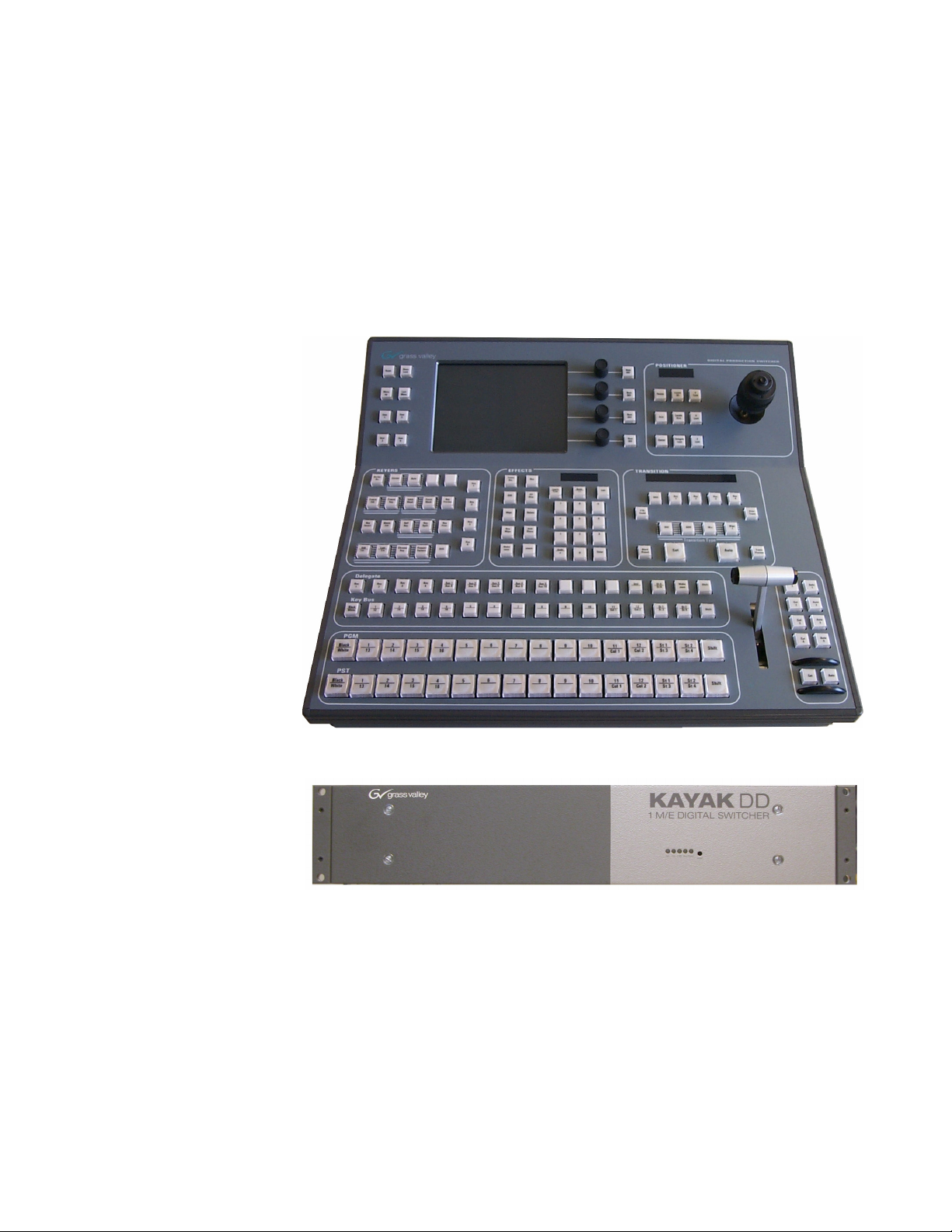
KayakDD-1 System Components
A KayakDD-1 Production Switcher system consists of a control panel with
integrated menu display (color TFT with touch-screen) and a 2 RU Video
Processor Frame.
Figure 1. KayakDD-1 Control Panel
KayakDD-1 Installation
Figure 2. KayakDD-1 Video Processor Frame
KayakDD Installation Planning Guide 7
Page 8
KayakDD-1 Installation
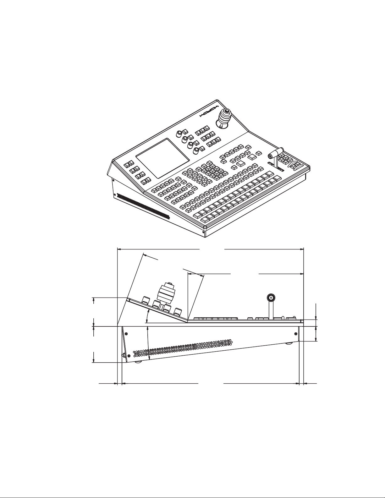
KayakDD-1 Control Panel Installation
Measurements
Figure 3. Kayak DD-1 Control Panel Measurements 1 of 2
2.55 in.
64.75 mm
3.19 in.
80.95 mm
8324_00_01_r0
0.40 in.
10.26 mm
20°
5.69 in.
144.53 mm
7°
16.46 in.
418 mm
15.66 in.
397.74 mm
10.23 in.
259.88 mm
0.60 in.
15.3 mm
1.31 in.
33.33 mm
0.39 in.
10 mm
8KayakDD Installation Planning Guide
Page 9
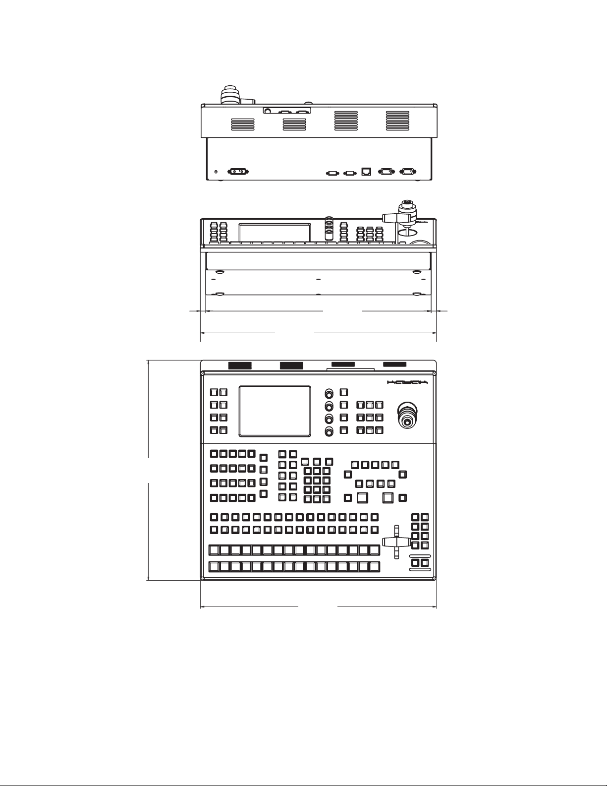
Figure 4. Kayak DD-1 Control Panel Measurements 2 of 2
8324_02_r0
KayakDD-1 Installation
15.46 in.
418 mm
0.39 in.
10 mm
17.64 in.
448 mm
16.85 in.
428 mm
0.39 in.
10 mm
17.64 in.
448 mm
KayakDD Installation Planning Guide 9
Page 10

KayakDD-1 Installation
Panel Mounting Options
Table Top
Surface Mount Cut Out Dimensions
Fastening to Table Top
The panel can be placed on a table. Gummed feet prevent accidental movement of the panel.
Cut a 16.93 in. (430 mm) x 15.75 in. (400mm) hole in table top for surface
mounting.
CAUTION At least 2 inches (50mm) of open space at the rear of the panel below the
mounting surface is required for proper cable clearance and air flow.
Four M4 thread drillings are available for fastening the panel to a table top
(Figure 5).
Figure 5. KayakDD-1 Panel Mounting Drillings
10.55 in.
268 mm
2.95 in.
75 mm
Four M4 thread drillings
for panel fastening
0.2 in.
5 mm
edge to drilling
centerline
17.24 in.
438 mm
drilling centerline
0.2 in.
5 mm
8324_03_r0
10 KayakDD Installation Planning Guide
Page 11

3.44 in.
87.5 mm
76.2 mm
KayakDD-1 Video Processor Frame Installation
Measurements
Figure 6. KayakDD-1 Frame Dimensions
19.0 in.
482 mm
18.3 in.
465 mm
3.5 in.
89 mm
3.0 in.
17.48 in.
444.05 mm
KayakDD-1 Installation
15.94 in.
404.9 mm
16.67 in.
423.4 mm
Air Flow
8324_04_r0
0.18 in.
4.5 mm
KayakDD Installation Planning Guide 11
Page 12

KayakDD-1 Installation
Rack Mounting
Figure 7. KayakDD-1 Rack Mounting
Slide rails
Recommended for mobil applications!
Not part of delivery!
CAUTION Mounting using only the front rack angles is permitted for fixed installations.
Additional support, like slide rails, is required for mobile applications (flight
case, OB van).
8324_05_r0
12 KayakDD Installation Planning Guide
Page 13

KayakDD-1 Cabling
N4067
GPI/O - Tally
LAN
RS 485
INPUT
REFERENCE
AUX
M/E
This device complies with part 15 of the FCC Rules. Operation is subject to the following two conditions:
(1) This device may not cause harmful interference, and
(2) this device must accept any interference received, including interference that may cause undesired operation.
AC POWER IN
100 - 240 V
max. 4A
50/60 Hz
DC POWER
OUT
J2
J3
J 4
J 5
J 6
J 7
J 8
PGM-A
CLEAN
PVW-A
CLEAN-PVW
AUX 1
AUX 2
AUX 3
AUX 4
AUX 5
AUX 6
AUX 7
AUX 8
AUX 9
AUX 10
J 9
J 10
J 11
J 12
J 13
J 14
J 15
J 16
J 17
J 18
Port 1
Port 2
Port 3
Port 4
Port 5
Port 6
J 19
J 20
J 21
J 22
J 24
J 23
J 25
IN 1
IN 2
IN 3
J 26
J 27
J 28
J 29
J 30
J 31
J 32
J 33
J 34
J 35
J 36
J 37
J 38
J 39
J 40
IN 4
IN 5
IN 6
IN 7
IN 8
IN 9
IN 10
IN 11
IN 12
IN 13
IN 14
IN 15
IN 16
J 41
J 42
ANALOG
J 44
J 43
grass valley
48V / 5A max.
KAYAK
DD
1 M/E DIGITAL SWITCHER
48V / 1,6A
3S13
Prof. Vid. Equipm.
Listed
Caution:
For continued protection against risk
of fire, repplace only with same type and rating of fuse.
2*T6,3A /H
250V
J1
Control Cabling
Figure 8. KayakDD-1 Standard Control Cabling
KayakDD-1 Installation
48V DC
Power Supply
alternatively
AC POWER IN
100 - 240 V
max. 4A
50/60 Hz
Caution:
For continued protection against risk
of fire, repplace only with same type and rating of fuse.
J1
110-240V AC
Power Supply
Keyboard
grass valley
M/E
PGM-A
PVW-A
J 4
J 5
2*T6,3A /H
250V
IN 1
J 25
Control Panel
Video Processor Frame
KAYAK
1 M/E DIGITAL SWITCHER
CLEAN
CLEAN-PVW
J 6
J 7
J 8
IN 2
IN 4
IN 3
IN 5
J 26
J 28
J 27
J 29
AUX 1
J 9
IN 6
J 30
AUX 2
AUX 3
J 10
IN 8
IN 7
J 32
J 31
INPUT
(1) This device may not cause harmful interference, and
(2) this device must accept any interference received, including interference that may cause undesired operation.
AUX 4
J 11
J 12
IN 10
IN 9
J 34
J 33
This device complies with part 15 of the FCC Rules. Operation is subject to the following two conditions:
DD
Suplied DC Interconnect Cable
AUX
AUX 5
J 13
IN 11
J 35
Mouse
AUX 6
J 14
IN 12
IN 13
J 36
J 37
Note:
Keyboard and Mouse not
manditory and not supplied.
CAT5 Crossover Cable
Port 1
Port 2
Port 3
J 19
J 20
AUX 7
AUX 8
AUX 9
AUX 10
Port 4
Port 5
J 15
J 16
J 17
IN 14
IN 16
IN 15
J 38
J 40
J 39
REFERENCE
J 22
J 18
ANALOG
J 42
J 41
RS 485
GPI/O - Tally
+
-
DC POWER
48V / 5A max.
J2
J 21
Port 6
J 24
J 23
N4067
LAN
R
Listed
Prof. Vid. Equipm.
3S13
J 44
J 43
+
-
ININOUT
48V / 1,6A
J3
48V DC
Power Supply
(Redudancy)
8324_07_r0
The KayakDD-1 system uses Ethernet, serial, parallel, and USB connections. Tally and GPI/O control are also available. A simple KayakDD-1
system consisting of a Control Panel and Video Processor frame uses pointto-point connections and does not require connection to an external
Ethernet Local Area Network (LAN).
Note
The point to point connection between the Control Panel and Video Processor
frame require swapped Transmit (TX) and Receive (RX) pairs. This is normally achieved with a crossover LAN cable or an Uplink port on a switch or
hub. The LAN cable supplied with the KayakDD system is a crossover cable.
A KayakDD system requires a LAN when components besides a Control
Panel and Video Processor frame are connected, or when external network
access to a file system is desired. An appropriately sized Ethernet switch
will be required. An existing facility Ethernet switch (not hub) can support
KayakDD if an adequate number of ports are available. Keep your facility
network and technical network separate in order to avoid network traffic
negatively affecting KayakDD system operation. An Ethernet hub or
switch will be necessary if cable runs exceed allowable maximums.
KayakDD Installation Planning Guide 13
Page 14

KayakDD-1 Installation
Table 1 details Ethernet specifications. All Ethernet components are to be
supplied by the customer.
Table 1. Ethernet Specifications
10Base-T and 100Base-T compatible.
Category 5 cable, 8 conductor twisted pair.
The system will work at 10Base-T with reduced performance.
100Base-T components are highly recommended.
RJ-45 male connector at each end of cable.
10Base-T: 984 ft. (300 m) maximum.
100Base-T: 328 ft. (100 m) maximum.
Use hub or switch to exceed maximum cable runs.
Dual: 10 and 100 Mb
RJ-45 auto-negotiating 10/100 Mb; number of ports required is
dependent upon system size.
Recommended. Configuration not required, but does not provide
remote monitoring capability.
May be used. Require configuration, but offers remote monitoring
capability.
Cables
Switch
Type
Connectors
Length
Speed
Ports
Unmanaged
Managed
Video Cabling
All KayakDD system video inputs and Aux outputs are configurable. For
cabling configuration flexibility, each input can be mapped to any
KayakDD panel source select button, and any KayakDD system video
signal can be mapped to any AUX output connectors.
Inputs
Non-looping video inputs on the back of the Video Processor frame are
numbered 1 through 16. Each receives a 270 MHz serial digital video signal.
Each input can be mapped to any KayakDD panel source select button.
Outputs
The KayakDD frame provides dedicated program and preview video
output connectors for the M/E. The main program output signal is available on two BNC connectors. All other outputs are available on one BNC
connector only. Any KayakDD video source can be routed to any Aux bus
output (1 through 10).
Reference Input
The looping reference input accepts analog 525 or 625 composite video.
Burst is not required, but typically facility reference color black is used.
KayakDD can auto-sense whether the reference is 525 or 625 and can
change the internal standard accordingly.
14 KayakDD Installation Planning Guide
Page 15

KayakDD-2 Installation
Kayak DD-2 System Components
A KayakDD-2 Production Switcher system consists of a control panel with
integrated menu display (color TFT with touch-screen) and a 3 RU Video
Processor Frame.
Figure 9. KayakDD-2 Control Panel
KayakDD-2 Installation
Figure 10. KayakDD-2 Video Processor Frame
KayakDD Installation Planning Guide 15
Page 16

KayakDD-2 Installation
Kayak DD-2 Control Panel Installation
Measurements
Figure 11. Kayak DD-2 Control Panel Measurements 1of 2
2.55 in.
64.75 mm
3.19 in.
80.95 mm
20°
5.69 in.
144.53 mm
7°
8324_08_r0
16.46 in.
418 mm
10.23 in.
259.88 mm
0.60 in.
15.3 mm
1.31 in.
33.33 mm
0.40 in.
10.26 mm
15.66 in.
397.74 mm
0.39 in.
10 mm
16 KayakDD Installation Planning Guide
Page 17

Figure 12. Kayak DD-2 Control Panel Measurements 2 of 2
8324_09_r0
KayakDD-2 Installation
0.39 in.
10 mm
16.5 in.
418 mm
31.9 in.
809 mm
31.1 in.
789 mm
31.9 in.
809 mm
0.39 in.
10 mm
Panel Mounting Options
Table Top
The panel can be placed on a table. Gummed feet prevent accidental movement of the panel.
Surface Mount Cut Out Dimensions
Cut a 31.2 in. (791mm) x 15.75 in. (400 mm) hole in table top for surface
mounting.
KayakDD Installation Planning Guide 17
Page 18

KayakDD-2 Installation
Fastening to Table Top
10.55 in.
268 mm
CAUTION At least 2 inches (50mm) of open space at the rear of the panel below the
mounting surface is required for proper cable clearance and air flow.
Four M4 thread drillings are available for fastening the panel to a table top
(Figure 13).
Figure 13. KayakDD-2 Panel Mounting Drillings
0.2 in.
5 mm
2.95 in.
75 mm
edge to drilling
centerline
31.46 in.
799 mm
drilling centerline
0.2 in.
5 mm
18 KayakDD Installation Planning Guide
Page 19

Frame
8324_11_r0
Measurements
Figure 14. KayakDD-2 Frame Dimensions
19.0 inch
482 mm
18.3 inch
465 mm
KayakDD-2 Installation
2.25 inch
57.15mm
15.5 inch
401.9 mm
5.2 inch
132.95 mm
17.2 inch
438 mm
15.6 inch
420.74 mm
0.3inch
7.5mm
KayakDD Installation Planning Guide 19
Page 20

KayakDD-2 Installation
Rack Mounting
Figure 15. KayakDD-2 Rack Mounting
Air Flow
Slide rails.
Recommended for mobil applications.
Not part of delivery.
CAUTION
Mounting using only the front rack angles is permitted for fixed installations.
Additional support, like slide rails, is required for mobile applications (flight
case, OB van).
Air
Flow
20 KayakDD Installation Planning Guide
Page 21

Cabling
KayakDD-2 Installation
FIGURE shows the basic control cabling of a KayakDD-2 system.
Figure 16. KayakDD-2 Standard Control Cabling
48V DC
Power Supply
(Redudancy)
Keyboard
Suplied DC Interconnect Cable
grass valley
P/P
PGM CLEANPVW CLEAN-PVW
100
KAYAK DD-2
0 212 390 010
grass valley
J 4 J 5 J 6 J 7 J 8
TYPE
SER. NO.
PART NO.
AC POWER IN
100 - 240 V
max. 4A
50/60 Hz
Caution:For continued protection against risk
of fire, repplace only with same type and rating of fuse.
2*T6,3A /H
J1
250V
J2
J3
IN 4
IN 2
IN 1
IN 3
J 26
J 28
J 25
J 27
DC POWER
IN
48V / 5A max.
OUT
48V / 1,6A
Mouse
Note:
Keyboard and Mouse not
manditory and not supplied.
USBP/S 2
3
4
Control Panel
Video Processor Frame
DD-2
KAYAK
2 M/E DIGITAL SWITCHER
AUX 1 AUX 2 AUX 3 AUX 4 AUX 5 AUX 6 AUX 7 AUX 8 AUX 9 AUX 10
J 9 J 10 J 11 J 12 J 13 J 14 J 15 J 16 J 17 J 18
IN 6
IN 5
J 30
J 29
J 31
J 45 J 46 J 47 J 48 J 49
PGM CLEANPVW CLEAN-PVW
This device complies with part 15 of the FCC Rules. Operation is subject to the following two conditions:
(1) This device may not cause harmful interference, and
(2) this device must accept any interference received, including interference that may cause undesired operation.
AUX 1-10
IN 8
IN 10
IN 12
IN 7
IN 9
IN 11
J 32
J 34
J 36
J 33
INPUT 1-16
M/E
J 35
IN 17
IN 25
IN 14
IN 16
IN 13
IN 15
J 38
J 40
J 37
J 39
IN 18
IN 19
J 50
J 51
IN 26
IN 27
J 58
J 59
ANALOG
J 42
J 41
REFERENCE
INPUT 17-32
IN 20
IN 21
J 52
J 53
IN 28
IN 29
J 60
J 61
CAT5 Crossover Cable
Port 1 Port 2 Port 3
J 19 J 20 J 21
Port 4 Port 5 Port 6
J 22 J 24J 23
RS 485
GPI/O - Tally
R
Listed
Prof. Vid. Equipm.
N4067
IN 22
J 54
IN 30
J 62
3S13
IN 23
IN 24
J 55
J 56
IN 31
IN 32
J 63
J 64
LAN
J 44J 43
J 57
J 65
8324_13_r0
48V DC
110-240V AC
Power Supply
Power Supply
(Redudancy)
The KayakDD-2 system employs the same type of control and video
cabling as the KayakDD-1 system, except it has 32 video inputs and 20 outputs. Refer to
KayakDD-1 Cabling
on page 13 for details.
KayakDD Installation Planning Guide 21
Page 22

KDD-PSU Power Supply Option
KDD-PSU Power Supply Option
The KDD-PSU option is a one rack unit, wide range AC power supply providing redundant power for KayakDD production switcher. Power output
is sufficient for two KayakDD-1 systems or one KayakDD-2 system.
Installation
8324_14_r0
Note
Figure 17. KDD-PSU Rack Installation
To ensure sufficient RAM Recorder buffer voltage, the cable length is limited
to 20 m. Standard KayakDD cables are not suitable for buffer voltage supply.
Cut fastening metal so that the
ventilation openings are not covered
22 KayakDD Installation Planning Guide
Page 23

Pin Assignments
RS 485 Port
RS 232 Port
Pin Assignments
Socket Pin Bus Controller Tributary
1 Chassis Ground Chassis Ground
D-9 Female
Pin 1Pin 5
Pin 6Pin 9
2 RxA (-) TxA (-)
3 TxB (+) RxB (+)
4 Signal Ground Signal Ground
5 Not used Not used
6 Signal Ground Signal Ground
7 RxB (+) TxB (+)
8 TxA (-) RxA (-)
9 Chassis Ground Chassis Ground
Socket Pin Signal
1 Chassis Ground
D-9 Female
Pin 1Pin 5
Pin 6Pin 9
2Transmit Data
3 Receive Data
4 Not used
5 Signal Ground
6 Not used
7 Clear to Send
8 Request to Send
9 Not used
Control Panel DC Power In
Socket Pin Signal
A1 48 V (+)
A2 48 V (-)
1234-
-
5
Pin A1
D-Sub Male
Pin 2Pin 1
Pin A2
Pin 5Pin 3
KayakDD Installation Planning Guide 23
Page 24

Pin Assignments
Frame DC Power In
Socket Pin Signal
A1 48 V (+)
A2 48 V (-)
1 Ground
2 Return Sense *
3+ 7 V (RAM Rec)
4-
48V Return *
5
Pin A1
D-Sub Male
Pin 2Pin 1
Pin A2
Pin 5Pin 3
Note Pins 2 and 5 must be connected in the plug of the external power supply unit.
Frame DC Power Out
Table 2.
Socket Pin Signal
A1 48 V (+)
D-Sub Female
Pin A2
Pin 1Pin 2
Pin A1
Pin 3Pin 5
A2 48 V (-)
1234-
-
5
24 KayakDD Installation Planning Guide
Page 25

Frame GPI/O – Tally
Socket Ribbon Cable 50-Pin D-Sub Signal
D-50 Female
Pin 18
Pin 1
Pin 34
Pin 33
Pin 17
Pin 50
Pin Assignments
11GPIInCom
234 GPIInCom
318GPIIn1
42GPIIn2
535 GPIIn3
619GPIIn4
73GPIIn5
836 GPIIn6
920GPIIn7
10 4 GPIIn8
11 37 GPIOutComA
12 21 GPIOut1A
13 5 GPIOut2A
14 38 GPIOut3A
15 22 GPIOut4A
16 6 GPIOutComB
17 39 GPIOut5B
18 23 GPIOut6B
19 7 GPIOut7B
20 40 GPIOut8B
21 24 GPIOutComC
22 8 GPIOut9C
23 41 GPIOut10C
24 25 GPIOut11C
25 9 GPIOut12C
26 42 GPIOutComD
27 26 GPIOut13D
28 10 GPIOut14D
29 43 GPIOut15D
30 27 GPIOut16D
31 11 GPIOutComE
32 44 GPIOut17E
33 28 GPIOut18E
34 12 GPIOut19E
35 45 GPIOut20E
36 29 GPIOutComF
37 13 GPIOut21F
38 46 GPIOut22F
39 30 GPIOut23F
40 14 GPIOut24F
41 47 GPIOutComG
42 31 GPIOut25G
43 15 GPIOut26G
44 48 GPIOut27G
45 32 GPIOut28G
46 16 GPIOutComH
47 49 GPIOut29H
48 33 GPIOut30H
49 17 GPIOut31H
50 50 GPIOut32H
KayakDD Installation Planning Guide 25
Page 26

Specifications
Specifications
Table 3. Mechanical
KayakDD-1 Video Processor Frame
Height 2RU 89 mm 3.5 inch
Width 482 mm 19 inch
Depth 430 mm 17 inch
Weight 6.5 kg 14.3 lbs
KayakDD-1 Control Panel
Width 448 mm 17.6 inch
Depth 418 mm 16.5 inch
Mounting Depth 33 – 81 mm 1.3 - 3.2 inch
Weight 7 kg 15.4 lbs
KayakDD-2 Video Processor Frame
Height 3 RU 134 mm 5.3 inch
Width 482 mm 19 inch
Depth 430 mm 17 inch
Weight 8.3 kg 18.3 lb
KayakDD-2 Control Panel
Width 809 mm 31.8 inch
Depth 418 mm 16.5 inch
Mounting Depth 33 – 81 mm 1.3 - 3.2 inch
Weight 10 kg 22 lb.
KDD-PSU Power Supply Option Frame
Height 1RU 44 mm 1.73 inch
Width 482 mm 19 inch
Depth 240 mm 9.45 inch
Weight 2.8 kg 6.2 lb.
Table 4. Environmental
Storage temperature -20∞C to +70∞C (-4∞F to 158∞F)
Operating temperature +5∞C to +40∞C (41∞F to 104∞F)
Relative humidity £ 95% non-condensing
Electromagnetic environment E2 (according to EN55103-1, -2)
Table 5. Control Panel Connection
Type of connection 10/100 Base T
Protocol TCP(UDP)/IP as in XtenDD
Cable and connectors CAT5 UTP, RJ45 connectors;
max. Cable length 100m / 300ft
1 Frame and 1 Panel connect without use of external hub/switch.
26 KayakDD Installation Planning Guide
Page 27

Specifications
Table 6. Power
KayakDD-1 Frame
Line voltage
Line frequency 50/60Hz +/- 5%
Power consumption max. 150W (max. 200W with 48V DC supply for panel)
Leakage current < 2.5 mA
RAMRecorder buffer voltage: 6..8V DC approx. 150 mA.
DC-OUT for control panel 48V DC, max 1.6A
KayakDD-1 Control Panel
DC-IN 48V DC In, max 1.3A
Power consumption max. 50W
KayakDD-2 Frame
Line voltage
Line frequency 50/60Hz +/- 5%
Power consumption max. 250W (max. 310W with 48V DC supply for panel)
Leakage current < 2 mA
RAMRecorder buffer voltage: . 6…8V DC approx. 150 mA
DC-OUT for control panel 48V DC, max 1.6A
KayakDD-2 Control Panel
DC-IN 48V DC In, max 1.3A
Power consumption max. 60W
KDD-PSU Frame
Line voltage 100V-240V AC +/-10%, power factor corrected
Line frequency 50/60Hz +/- 5%
Power consumption max. 375W
Leakage current < 2 mA at 250V AC
DC-OUT 2x 48V DC, total 6A max
EXT BATT IN 12V … 24V, 0.5A
RAM Recorder buffer voltage: 7V DC, max 300mA. (Only with ext. battery input or AC In)
100V-240V AC +/-10% autorange, power factor corrected (48V / 5A
DC Input for ext. redundancy)
100V-240V AC +/-10% autorange, power factor corrected (48V / 5A
DC Input for ext. redundancy)
KayakDD Installation Planning Guide 27
Page 28

Specifications
Table 7. Serial Digital Video Inputs
Format ITU-R656, 270Mbit/s
Number of Inputs
Return loss > 15dB, 5-270MHz
Type of Connector 75 ohm BNC (SMPTE 259M)
Nominal Amplitude 800mV peak-to-peak terminated
Autophasing range 53 msec
Channel Coding conforms to SMPTE RP-259M
Ancillary Data Blanked or passed (user selectable)
Embedded audio Blanked or passed (user selectable)
EDH Blanked
Input Impedance 75 ohm
Max cable length 225 meters (738ft)
KayakDD-1: 16
KayakDD-2: 32
Table 8. Serial Digital Video Outputs
Format ITU-R656, 270Mbit/s
Number of Outputs
Return loss > 15dB, 5-270MHz
Type of Connector 75 ohm BNC (SMPTE 259M)
Nominal Amplitude 800mV peak-to-peak +/-10% (SMPTE 259M)
Rise & Fall Times
Jitter ITU R 601/656
Output Impedance 75 ohm
DC Offset < 50mV with 75 ohm termination
Table 9. Analog Reference Input
Video Standard
Return loss > 40dB, up to 5MHz
Connectors 2 BNC loop through
Impedance 75 ohm external
KayakDD-1: 15
KayakDD-2: 20
400 to 1400picoseconds 75 ohm termination
between 20% and 80% amplitude
525 line (59.94Hz/60Hz) or 625 line (50Hz) BNC, 0.3V sync,
black-burst or CCVS
28 KayakDD Installation Planning Guide
 Loading...