

Page 1
KAM-ENC-2AES
KAMELEON SERIES MODULES
Instruction Manual
SOFTWARE VERSION 4.0.1
071835500
DECEMBER 2004
Page 2

Contacting Grass Valley
Region Voice Fax Address Web Site
North America (800) 547-8949
Support: 530-478-4148
Pacific Operations +852-2585-6688
Support: 852-2585-6579
U.K., Asia, Middle East +44 1753 218 777 +44 1753 218 757
France +33 1 45 29 73 00
Germany, Europe +49 6150 104 782 +49 6150 104 223
Copyright © Thomson Broadcast and Media Solutions All rights reserved.
Grass Valley Web Site
Sales: (530) 478-3347
Support: (530) 478-3181
+852-2802-2996
Grass Valley
P.O. Box 599000
Nevada City, CA 959597900 USA
www.thomsongrassvalley.com
The www
Online User Documentation
.thomsongrassvalley.com web site offers the following:
— Current versions of product catalogs, brochures,
data sheets, ordering guides, planning guides, manuals, and release notes
in .pdf format can be downloaded.
FAQ Database
— Solutions to problems and troubleshooting efforts can be
found by searching our Frequently Asked Questions (FAQ) database.
Software Downloads
— Software updates, drivers, and patches can be down-
loaded.
2 KAM-ENC-2AES Instruction Manual
Page 3

Contents
Preface
. . . . . . . . . . . . . . . . . . . . . . . . . . . . . . . . . . . . . . . . . . . . . . . . . . . . . . . . . . . . . . . . . . . . . 5
About This Manual . . . . . . . . . . . . . . . . . . . . . . . . . . . . . . . . . . . . . . . . . . . . . . . . . . . . . 5
KAM-ENC-2AES Kameleon Series Module
Introduction . . . . . . . . . . . . . . . . . . . . . . . . . . . . . . . . . . . . . . . . . . . . . . . . . . . . . . . . . . . 7
Installation . . . . . . . . . . . . . . . . . . . . . . . . . . . . . . . . . . . . . . . . . . . . . . . . . . . . . . . . . . . . 8
System Requirements . . . . . . . . . . . . . . . . . . . . . . . . . . . . . . . . . . . . . . . . . . . . . . . . . 8
Frame Capacity . . . . . . . . . . . . . . . . . . . . . . . . . . . . . . . . . . . . . . . . . . . . . . . . . . . . . . 8
Module Placement in the 2000T3NG Kameleon Frame. . . . . . . . . . . . . . . . . . . . . 9
Installing the Front and Rear Modules. . . . . . . . . . . . . . . . . . . . . . . . . . . . . . . . . 9
Cabling . . . . . . . . . . . . . . . . . . . . . . . . . . . . . . . . . . . . . . . . . . . . . . . . . . . . . . . . . . . . 12
SDI Video In . . . . . . . . . . . . . . . . . . . . . . . . . . . . . . . . . . . . . . . . . . . . . . . . . . . . . . 12
AES Audio Inputs . . . . . . . . . . . . . . . . . . . . . . . . . . . . . . . . . . . . . . . . . . . . . . . . . 12
AES Audio Outputs. . . . . . . . . . . . . . . . . . . . . . . . . . . . . . . . . . . . . . . . . . . . . . . . 12
Composite Video Out . . . . . . . . . . . . . . . . . . . . . . . . . . . . . . . . . . . . . . . . . . . . . . 12
Power Up . . . . . . . . . . . . . . . . . . . . . . . . . . . . . . . . . . . . . . . . . . . . . . . . . . . . . . . . . . . . 13
Operation Indicator LEDs . . . . . . . . . . . . . . . . . . . . . . . . . . . . . . . . . . . . . . . . . . . . 14
Configuration and Adjustments . . . . . . . . . . . . . . . . . . . . . . . . . . . . . . . . . . . . . . . . . 15
Configuration Summary. . . . . . . . . . . . . . . . . . . . . . . . . . . . . . . . . . . . . . . . . . . . . . 15
Newton Control Panel Configuration . . . . . . . . . . . . . . . . . . . . . . . . . . . . . . . . . . 19
Web Browser Interface . . . . . . . . . . . . . . . . . . . . . . . . . . . . . . . . . . . . . . . . . . . . . . . 20
Web Page Operations and Functional Elements. . . . . . . . . . . . . . . . . . . . . . . . . . 22
Status and Identification Header. . . . . . . . . . . . . . . . . . . . . . . . . . . . . . . . . . . . . 22
Initial Configuration Process Overview . . . . . . . . . . . . . . . . . . . . . . . . . . . . . . . . . . 23
KAM-ENC-2AES Links and Web Pages . . . . . . . . . . . . . . . . . . . . . . . . . . . . . . . . . . 24
Status Web Page. . . . . . . . . . . . . . . . . . . . . . . . . . . . . . . . . . . . . . . . . . . . . . . . . . . . . 25
Color-coded Status Indicators and Links . . . . . . . . . . . . . . . . . . . . . . . . . . . . . . 25
Status/Front Module Properties . . . . . . . . . . . . . . . . . . . . . . . . . . . . . . . . . . . . . 25
Warning/Fault Summary. . . . . . . . . . . . . . . . . . . . . . . . . . . . . . . . . . . . . . . . . . . 27
Input/Output Configuration Web Page . . . . . . . . . . . . . . . . . . . . . . . . . . . . . . . . 28
Functional View Web Page . . . . . . . . . . . . . . . . . . . . . . . . . . . . . . . . . . . . . . . . . . . 31
SDI In Web Page . . . . . . . . . . . . . . . . . . . . . . . . . . . . . . . . . . . . . . . . . . . . . . . . . . . . 32
Video Input Select Web Page. . . . . . . . . . . . . . . . . . . . . . . . . . . . . . . . . . . . . . . . . . 34
View Selection . . . . . . . . . . . . . . . . . . . . . . . . . . . . . . . . . . . . . . . . . . . . . . . . . . . . 35
Video Selection Settings . . . . . . . . . . . . . . . . . . . . . . . . . . . . . . . . . . . . . . . . . . . . 35
Output Timing Selection. . . . . . . . . . . . . . . . . . . . . . . . . . . . . . . . . . . . . . . . . . . . 35
Advanced VBI Configuration. . . . . . . . . . . . . . . . . . . . . . . . . . . . . . . . . . . . . . . . 36
Frame Sync Web Page. . . . . . . . . . . . . . . . . . . . . . . . . . . . . . . . . . . . . . . . . . . . . . . . 38
Timing Adjustment . . . . . . . . . . . . . . . . . . . . . . . . . . . . . . . . . . . . . . . . . . . . . . . . 38
Freeze Mode Selection. . . . . . . . . . . . . . . . . . . . . . . . . . . . . . . . . . . . . . . . . . . . . . 38
Video Processing Web Page. . . . . . . . . . . . . . . . . . . . . . . . . . . . . . . . . . . . . . . . . . . 40
Video Processing Controls . . . . . . . . . . . . . . . . . . . . . . . . . . . . . . . . . . . . . . . . . . 40
Clipping Controls. . . . . . . . . . . . . . . . . . . . . . . . . . . . . . . . . . . . . . . . . . . . . . . . . . 42
KAM-ENC-2AES Instruction Manual 3
Page 4

Contents
Reset To Default . . . . . . . . . . . . . . . . . . . . . . . . . . . . . . . . . . . . . . . . . . . . . . . . . . 42
VBI Encode For Composite Output . . . . . . . . . . . . . . . . . . . . . . . . . . . . . . . . . . . . 44
Composite Out Web Page . . . . . . . . . . . . . . . . . . . . . . . . . . . . . . . . . . . . . . . . . . . . 46
Output Video Adjustments . . . . . . . . . . . . . . . . . . . . . . . . . . . . . . . . . . . . . . . . . 46
AES Inputs Web Page . . . . . . . . . . . . . . . . . . . . . . . . . . . . . . . . . . . . . . . . . . . . . . . 49
Audio Channel Pairing Web Page . . . . . . . . . . . . . . . . . . . . . . . . . . . . . . . . . . . . . 50
Audio Sync Web Page . . . . . . . . . . . . . . . . . . . . . . . . . . . . . . . . . . . . . . . . . . . . . . . 51
Enable Auto Track. . . . . . . . . . . . . . . . . . . . . . . . . . . . . . . . . . . . . . . . . . . . . . . . . 51
Delay Adjustments . . . . . . . . . . . . . . . . . . . . . . . . . . . . . . . . . . . . . . . . . . . . . . . . 51
Audio Processing Web Page . . . . . . . . . . . . . . . . . . . . . . . . . . . . . . . . . . . . . . . . . . 53
Audio Gain. . . . . . . . . . . . . . . . . . . . . . . . . . . . . . . . . . . . . . . . . . . . . . . . . . . . . . . 53
Output Processing. . . . . . . . . . . . . . . . . . . . . . . . . . . . . . . . . . . . . . . . . . . . . . . . . 53
Selecting Output Resolution . . . . . . . . . . . . . . . . . . . . . . . . . . . . . . . . . . . . . . . . 54
AES Outputs Web Page . . . . . . . . . . . . . . . . . . . . . . . . . . . . . . . . . . . . . . . . . . . . . . 55
E-MEM Configuration Web Page. . . . . . . . . . . . . . . . . . . . . . . . . . . . . . . . . . . . . . 56
File Operations. . . . . . . . . . . . . . . . . . . . . . . . . . . . . . . . . . . . . . . . . . . . . . . . . . . . 58
Slot Configuration. . . . . . . . . . . . . . . . . . . . . . . . . . . . . . . . . . . . . . . . . . . . . . . . . . . 61
Slot Identification . . . . . . . . . . . . . . . . . . . . . . . . . . . . . . . . . . . . . . . . . . . . . . . . . 61
Locate Module . . . . . . . . . . . . . . . . . . . . . . . . . . . . . . . . . . . . . . . . . . . . . . . . . . . . 61
Slot Memory. . . . . . . . . . . . . . . . . . . . . . . . . . . . . . . . . . . . . . . . . . . . . . . . . . . . . . 61
Frame Heath Reporting . . . . . . . . . . . . . . . . . . . . . . . . . . . . . . . . . . . . . . . . . . . . 63
Hardware Switch Controls . . . . . . . . . . . . . . . . . . . . . . . . . . . . . . . . . . . . . . . . . 63
Slot SNMP Trap Reports . . . . . . . . . . . . . . . . . . . . . . . . . . . . . . . . . . . . . . . . . . . 63
Software Update Web Page. . . . . . . . . . . . . . . . . . . . . . . . . . . . . . . . . . . . . . . . . . . 64
Specifications. . . . . . . . . . . . . . . . . . . . . . . . . . . . . . . . . . . . . . . . . . . . . . . . . . . . . . . . . 65
Service . . . . . . . . . . . . . . . . . . . . . . . . . . . . . . . . . . . . . . . . . . . . . . . . . . . . . . . . . . . . . . 69
Troubleshooting . . . . . . . . . . . . . . . . . . . . . . . . . . . . . . . . . . . . . . . . . . . . . . . . . . . . 69
Index
. . . . . . . . . . . . . . . . . . . . . . . . . . . . . . . . . . . . . . . . . . . . . . . . . . . . . . . . . . . . . . . . . . . . . . 71
4 KAM-ENC-2AES Instruction Manual
Page 5

Preface
About This Manual
This manual describes the features of the Kameleon multi-function
modules that are part of the Kameleon Media Processing System. As part
of this module family, it is subject to Safety and Regulatory Compliance
described in the Kameleon/2000 Series frame and power supply documentation (see the
Kameleon 2000 Series Frames Instruction Manual
).
KAM-ENC-2AES Instruction Manual 5
Page 6

Preface
6 KAM-ENC-2AES Instruction Manual
Page 7

KAM-ENC-2AES Kameleon Series Module
Introduction
This manual provides installation, operation and configuration information for the KAM-ENC-2AES Kameleon Series module.
The Kameleon KAM-ENC-2AES multifunction module provides broadcast
quality conversion of SD video to NTSC/PAL analog composite video
output. AES audio can be input to the module, processed and synchronized, and sent to two AES audio output channels.
This module features:
•SD conversion to broadcast quality NTSC/PAL analog video,
•Two 48 kHz AES digital audio streams input to the module providing
two balanced or unbalanced AES outputs,
•Audio and video delay, synchronization and processing amplifiers,
• Powerful line-by-line VBI processing including user-configuration of
active video lines for carrying data,
• 4x4 audio router for mapping audio channels to specific AES streams,
•Audio and video test generators,
•Hot swappable,
•5 user-programmable E-MEM registers,
• Save/load module configuration files to a networked PC,
•SNMP monitoring capability,
•Web browser GUI (graphical user interface), and
• Support for Newton Control System and NetConfig Network Configuration application.
Note
KAM-ENC-2AES Instruction Manual 7
KAM-ENC-2AES operation requires 2000NET Network Interface Module
hardware revision 01A1 or greater with software version 3.2.2 or greater.
Systems installed in the 2000T3N frame require the 2000FAN fan sled (refer
to Figure 3 on page 11).
Page 8

Installation
Installation
1.
To install the Kameleon modules, perform the following steps:
2.
All Kameleon modules can be inserted and removed from a 2000 Series
Kameleon Frame with power on.
Place the KAM-AES-R passive rear module in a rear frame slot and
tighten the screws on each side of the rear module.
Cable the signal ports.
Note
Remove the front processing module before removing the rear I/O module.
System Requirements
For proper operation of the KAM-ENC-2AES modules, the frame must be
a 2000T1DNG or 2000T3NG which include the following components:
• 2000NET module (software version 3.2.2 or later recommended for full
functionality)
• 2000GEN module
•Dual 130W power supplies in the 2000T1DNG frame
• Single 240W power supply and 2000FAN in the 2000T3NG frame
Frame Capacity
The 1 RU 2000T1DNG (with dual 130W power supplies, 2000NET and
2000GEN modules) frames have no Kameleon module capacity limitations.
The 3 RU 2000T3NG (single 240W p/s, 2000FAN, 2000NET and 2000GEN
modules) frame can be fully populated with Kameleon modules when the
2000FAN fan sled and two power sleds are installed.
Table 1 provides the maximum Kameleon module count for frame types.
Table 1. Power, Cooling, and Module Capacity of 2000 Series Kameleon Frames
Item
KAM-ENC-2AES Module set 12 4
8 KAM-ENC-2AES Instruction Manual
2000T3NG
Kameleon Frame
Capacity
2000T1DNG
Kameleon Frame
Capacity
Page 9
1.
Module Placement in the 2000T3NG Kameleon Frame
There are twelve slot locations in both the front and rear of a 3 RU frame to
accommodate 2000 and Kameleon Series media modules (audio/video
signal handling modules). The Kameleon media modules consist of a
two-module set with a front processing media module and a passive rear
module that can be plugged into any of the 12 frame slot pairs. The rear
modules provide the input and output interface connectors.
Installing the Front and Rear Modules
To install a KAM-ENC-2AES module set in the 2000 Series frame:
Locate a vacant slot in the rear of the 3 RU frame (Figure 1).
Figure 1. 2000T3NG Kameleon Frame Rear View
Mid-frame
motherboard
with power and
communication buses
Front-rear module
direct connection
cutout
Installation
Open frame area
for front-rear module
direct connection
Six rear
module slots
Network and reference
input connections
8346_01
Six rear
module slots
KAM-ENC-2AES Instruction Manual 9
Page 10
Installation
2.
3.
4.
Insert the KAM-AES-R passive rear module into the vacant rear slot of
the frame as illustrated in Figure 2.
Figure 2. Installing Passive Rear Module
2000 frame (rear view)
Board edge guides
(both sides)
Rear alignment
post and receptacle
AES
V1
1
J11
SIG
Verify that the module connector seats properly against the midplane.
Using a crossblade screwdriver, tighten the two screw locks to secure
the module in the frame.
Screw lock
(both sides)
AES
2
J9
J10
CVO
AES
AES
AES
1
2
J7
J8
AES
3
4
J4
J5
J6
SD0
3
AES
AES
J3
2900
4
PRM-7
J1
J2
8345_01
KAM-AES-R module
10 KAM-ENC-2AES Instruction Manual
Page 11
5.
6.
7.
Locate the corresponding front media slot (1 -12) in the frame. The 3 RU
frame front view is illustrated in Figure 3.
Figure 3. 2000T3NG Kameleon Frame, Front Slots
Network Slot (13)
8.
Reference Distribution Slot (15)
Main Power Supply Slot (19)
Installation
(1)
(2)
(3)
(4)
(5)
(6)
(13)
(15)
(7)
(8)
(9)
(10)
(11)
(12)
Secondary Power
Supply Slot (21)
Front Media Slots (1-12)
Fan Sled
Slot (20)
With the component side up, insert the processing module in the
corresponding front slot (see Figure 4).
Verify that the module connector seats properly against the midplane
and rear module connector.
Press firmly on both ejector tabs to seat the module.
Figure 4. Installing Front Media Module
2000 Frame (front view)
Alignment post and receptacle
8173-04
Board edge
guides
Board edge
guides
8343_10
KAM-ENC-2AES Instruction Manual 11
Page 12
Installation
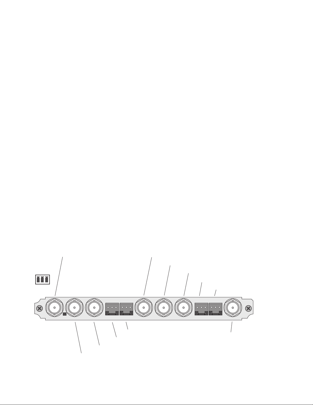
Cabling
All cabling to the module is done on the KAM-AES-R passive rear module
shown in Figure 5.
SDI Video In
Connect the SDI video to be encoded to connector J11, labeled
AES Audio Inputs
Two unbalanced AES audio inputs are available at connectors J9 and J10 or
two balanced AES audio inputs are available at connectors J7 and J8. Input
type must be selected as explained on the Input/Output Configuration Web
Page on page 28. Connect balanced or unbalanced AES audio to the correct
type of audio connectors.
AES Audio Outputs
Two AES audio outputs are available at unbalanced BNC connectors J4 and
J5 or balanced 3-pin connectors J2 and J3. The choice between balanced or
unbalanced outputs must be made on the
Page
on page 28.
Connect balanced audio to the 3-pin connector as shown in the connector
pinout.
Composite Video Out
The Composite video is output at BNC connector J6, labeled
V1
.
Input/Output Configuration Web
CVO
.
Figure 5. KAM-AES-R Input/Output Connectors
Connector
pinout
+ – G
SIG
J11
J11 VI, SDI Video In
AES
SIG
1
AES
2
J10
J10 AES 1, Unbalanced Audio In
AES
1
J9
J8
J8 AES 1, Balanced Audio In
J9 AES 2 Unbalanced Audio In
CVO
AES
2
J7
J7 AES 2, Balanced Audio In
J6 CVO, Composite Output
J5 AES1, Unbalanced Audio Output
J4 AES2, Unbalanced Audio Output
AES
3
J6
AES
4
J5
J4
J3 AES1, Balanced Audio Output
J2 AES2, Balanced Audio Output
AES
3
AES
4
J3
J2
J1 SDO (Not Used)
SD0
2900
PRM-7
J1
8355_01
12 KAM-ENC-2AES Instruction Manual
Page 13
Power Up
The front LED indicators are illustrated in Figure 6.
Figure 6. Front and Rear Module Indicator LEDs
FAULT – Red diagnostic LED is off during normal operation
COMM – Yellow LED on during remote control communication
CONF – Yellow LED on when module is initializing or processing control data
PWR – Green diagnostic LED on indicates power OK
Power Up
Processor Module
Front Edge
For factory use.
GND – Digital ground
D1 D2 D3 D4 D5 D6 D7 D8
Ejector Tabs
SIG
J11
AES
SIG
AES
1
2
J10
AES
1
J9
J8
CVO
AES
2
J7
AES
J6
AES
3
4
J5
3
AES
J3
J4
SD0
AES
4
J2
2900
PRM-7
J1
Signal Present green LED
A green Signal Present LED can be seen on the Passive Rear Module (PRM)
when a valid input signal is present.
8345_03
KAM-ENC-2AES Instruction Manual 13
Page 14

Power Up
Operation Indicator LEDs
Table 2 provides a complete list of possible operating conditions and the
resulting indicator status.
A red FAULT LED indicates an error situation. Table 2 describes signal
output and LED indications for the various input/reference combinations
and user settings.
Table 2. Indicator LEDs and Conditions Indicated
LED Indication Condition
Off Normal operation
Fault
(red)
COMM
(yellow)
CONF
(yellow)
PWR
(green)
On continuously Module has detected internal fault
Long flash One of the inputs is missing or is wrong standard
Short flash Errors present in SDI and/or AES/EBU input
Off No activity on frame communication bus
Three flash/off pattern Module Location command received from a remote control system
Short flash Activity present on the frame communication bus
Off Module is in normal operating mode
Three flash/off pattern Module Location command received from a remote control system
On continuously
Off No power to module or module’s DC/DC converter failed
On continuously Normal operation, module is powered
Module is initializing, changing operating modes or updating firmware. (When solid on along
with Fault LED on, board has failed to load data.)
Note
The yellow COMM and CONF LEDs are used for the module location function
that is enabled using the 2000NET GUI. The module location function causes
these LEDs to repeatedly flash concurrently three times followed by an off
state of 900 ms duration (see Slot Configuration on page 61).
14 KAM-ENC-2AES Instruction Manual
Page 15

Configuration and Adjustments
KAM-ENC-2AES configuration and monitoring can be performed using a
web browser GUI interface or a networked Newton Control Panel. This
section provides an overview of each of these controls along with the configuration parameters available with each type of control device.
Configuration Summary
The configuration parameters and monitoring functions available with the
web browser interface and the Newton Control Panel are summarized in
Table 3. The parameter defaults, choices, ranges, and resolution are pro-
vided for each function
Table 3. Summary of KAM-ENC-2AES Configuration Controls
Function Default
Set KAM-AES-R rear module audio inputs Unbalanced Unbalanced or Balanced
Set KAM-AES-R rear module audio outputs Unbalanced Unbalanced or Balanced
SDI In web page view selection Summary Summary or Detail
Set error reporting for SDI input video Enabled Enabled or Disabled
Input status loss of signal report Enable Enable or Disable
Select video line rate Auto 525, 625, or Auto
Frame Reference loss of signal status Report Report or No Report
SDI Input Error warning status
Select output timing source Video In
Define VBI data lines None
Main video horizontal timing adjustment 0
Main video vertical timing adjustment 0
Freeze mode selection (Video In timing
source)
Warn SDI
Errors
None
Range/Choices
Resolution
Warn SDI Errors or
No Warning
Video In or
Internal Frame Reference
525: None, 21/284,
22/285, 23/286 or 24/287
625: None, 24/337,
25/338, 26/339 or 27/340
or 28/341
525: 0 to 857.5 pixels
625: 0 to 863.5
(0.5 pixel steps)
525: 0 to 524 lines
625: 0 to 624 lines
(1 line steps)
None, Field 1, Field 2,
or Frame
Configuration and Adjustments
Web Page/
Function Name
I/O Config/
Unbalanced or Balanced radio button
I/O Config/
Unbalanced or Balanced radio button
SDI In/
Summary or Detail radio button
SDI In/Detail View/
Check or uncheck error checkboxes
Video Input Select/
Input Status Report Loss of Signal
checkbox
Video Input Select/
Video Line Rate radio button
Video Input Select/
Frame Reference Report Loss of Signal
checkbox
Video Input Select/
SDI Input Errors Warn SDI Errors
Warn SDI Errors checkbox
Video Input Select/
Output Timing Selection radio buttons
Video Input Select/
Advanced (VBI Config) radio button
VBI/Data Lines Last Data Line radio button
Frame Sync/
HTiming control (pixels)
Frame Sync/
VTiming control (Lines)
Frame Sync/
Freeze Mode Selection radio buttons
Newton
Panel
N/A
N/A
N/A
N/A
N/A
N/A
N/A
N/A
N/A
N/A
HTiming
VTiming
N/A
KAM-ENC-2AES Instruction Manual 15
Page 16

Configuration and Adjustments
Table 3. Summary of KAM-ENC-2AES Configuration Controls
Function Default
Freeze mode selection (Internal timing
source)
Enable video processing Enable
Video gain lock Off On or Off
Main video contrast/Y gain 100%
Main video chroma gain 100%
Enable Clip controls Disable Enable or Disable
Apply clips to VBI Off On or Off
Main video soft/Y black clip -6.8%
Main video hard/video black clip
Main video soft/Y white clip 109%
Main video hard/video white clip 138.7%
Main video brightness/Y offset 0%
Main video hue/chroma phase 0.0
Main video B-Y gain 100%
Main video B-Y balance/offset 0.0
Main video R-Y gain 100%
Main video R-Y balance/offset 0.0
Blank SDI VBI lines (line-by-line) Not Blanked Blank/Not Blanked
VBI encoding add setup (525 only) Add Setup or No Setup
Add setup to composite output Setup Setup or No Setup
Cross Color Removal (composite out) Disable Enable or Disable
Chrominance Signal (composite out) Enable Enable or Disable
None
-37.3% (525)
-30.0% (625)
Range/Choices
Resolution
None, AutoBlack,
AutoFreeze, Field 1,
Field 2, or Frame
Disable, Enable,
or Color Bars
50 to 149.6%
(0.4% steps)
50 to 149.6%
(0.4% steps)
-6.8 to 109%
(0.1% steps)
-37.3 to -7.3% (525)
-30.0 to 0% (625)
(0.1% steps)
-6.8 to 109%
(0.1% steps)
-6.8 to 138.7%
(0.1% steps)
-3.55 to 3.44%
(0.11% steps)
± 89.8 degrees
(0.1 degree steps)
50 to 149.6%
(0.4% steps)
-3.55 to 3.44%
(0.11% steps)
50 to 149.6%
(0.4% steps)
-3.55 to 3.44%
(0.11% steps)
Web Page/
Function Name
Frame Sync/
Freeze Mode Selection radio buttons
Video Proc/
Video Processing radio buttons
Video Proc/
Video Gain Lock radio buttons
Video Proc/Standard View
Y Gain control (%)
Video Proc/Standard View
Chroma Gain control (%)
Video Proc/Standard View
Clip Settings radio buttons
Video Proc/Standard View
Apply Clips to VBI checkbox
Video Proc/Standard View
Soft/Y Black Clip control (%)
Video Proc/Standard View
Hard/Video Black Clip control (%)
Video Proc/Standard View
Soft/Y Clip control (%)
Video Proc/Standard View
Hard/Video Clip control (%)
Video Proc/Advanced View
Brightness/Y Offset control (%)
Video Proc/Advanced View
Hue/Phase control (degrees)
Video Proc/Advanced View
B-Y Gain control (%)
Video Proc/Advanced View
B-Y Balance/Offset control (%)
Video Proc/Advanced View
R-Y Gain control (%)
Video Proc/Advanced View
R-Y Balance/Offset control (%)
VBI SDI/
Field 1/Field 2 Blank VBI line checkboxes
VBI Encode/
Check corresponding line Setup checkbox
Composite Out/
Setup or No Setup radio button
Composite Out/
Cross Color Removal
Disable or Enable radio button
Composite Out/
Chrominance Signal
Disable or Enable radio button
Newton
Panel
N/A
N/A
N/A
YGain
ChroGain
N/A
N/A
YBClip
VBClip
YWClip
VidWClip
YOffset
ChroPhs
BYGain
N/A
RYGain
N/A
N/A
N/A
N/A
N/A
N/A
16 KAM-ENC-2AES Instruction Manual
Page 17

Configuration and Adjustments
Table 3. Summary of KAM-ENC-2AES Configuration Controls
Function Default
Burst Signal (composite out) Enable Enable or Disable
Adjust Coarse Delay (composite out) 0
Adjust Fine Delay (composite out) 0
Composite Out video gain 100%
Output Video Adjustment Calibrated
Adjust Composite Out luma gain 100%
Adjust Composite Out black level 0.0
Adjust Composite Out chroma gain 0.0
AES input sample rate Disable Enable or Disable
AES input loss of signal report Enable Enable or Disable
AES input AES error warning Enable Enable or Disable
Adjust Composite Out hue (525 only) 0.0
Audio Pair 1 and Pair 2 channel swap – –
Pair1ChA=
Str1.Ch1
Pair1ChB=
Define audio Pair 1 and Pair 2 Ch A and Ch
B audio streams
Enable auto tracking for Pair 1 and 2 Ch A
and Ch B
Lock Pair 1 Ch A and Ch B delay adjustments and Pair 2 Ch A and Ch B delay
adjustments
Audio Pair 1 Ch A delay adjust
Audio Pair 1 Ch B delay adjust
Audio Pair 2 Ch A delay adjust
Audio Pair 2 Ch B delay adjust
Str1.Ch2
Pair2ChA=
Str2.Ch1
Pair2ChB=
Str2.Ch2
On On or Off
Locked Locked or Unlocked
0 ms
Range/Choices
Resolution
0 to 4095.5 pixels
(0.5 pixel steps)
0 to 100%
(1% steps)
61 to 138.5%
(0.5% steps)
Calibrated or
User adjustable
50 to 150%
(1% steps)
-7.5 to + 15%
(0.1% steps)
50 to 150%
(1% steps)
± 22.5 degrees
(0.5 degree steps)
Str1.Ch1
Str1.Ch2
Str2.Ch1
Str2.Ch2
Silence
0 to 5180 ms
(20 ms steps)
Web Page/
Function Name
Composite Out/
Burst Signal
Disable or Enable radio button
Composite Out/
Delay Coarse (pixels)
Composite Out/
Delay Fine (%)
Composite Out/
Output Video Gain (%)
Composite Out/
Calibrated or User Adjustable radio button
Composite Out/User Adjustable view
Luma Gain (%)
Composite Out/User Adjustable view
Black Level (%)
Composite Out/User Adjustable view
Chroma Gain (%)
AES Inputs/
Sample Rate Convert disable radio button
AES Inputs/
Loss of Signal Report checkbox
AES Inputs/
AES Error Warn checkbox
Composite Out/User Adjustable view
Hue (deg)
Audio Channel Pairing/
Pair 1 and 2 Ch A and Ch B radio buttons
Audio Channel Pairing/
Pair 1 and 2 Ch A and Ch B radio buttons
Audio Sync/
Pair 1 and Pair 2 Ch A and Ch B
Enable Auto Track On checkbox
Audio Sync/
Pair 1 and Pair 2 Ch A and Ch B
Channel Lock Locked checkbox
Audio Sync/
Pair 1 and Pair 2 Ch A and Ch B
Delay controls (ms)
Newton
Panel
N/A
N/A
N/A
OVidGain
N/A
N/A
N/A
N/A
N/A
N/A
N/A
N/A
Pair1Swp
Pair2Swp
Str1.Ch1
Str1.Ch2
Str2.Ch1
Str2.Ch2
Silence
N/A
N/A
Ch1ADly
Ch1BDly
Ch2ADly
Ch2BDly
KAM-ENC-2AES Instruction Manual 17
Page 18

Configuration and Adjustments
Table 3. Summary of KAM-ENC-2AES Configuration Controls
Function Default
Select audio processing option for Pair 1
Ch A’ and Ch B’ and Pair 2 Ch A’ and Ch B’
Lock Pair 1 Ch A and Ch B gain adjustments
and Pair 2 Ch A and Ch B gain adjustments
Audio Pair 1 Ch A gain adjust
Audio Pair 1 Ch B gain adjust
Audio Pair 2 Ch A gain adjust
Audio Pair 2 Ch B gain adjust
Set output resolution for Pair channels 20 bit 20 bit or 24 bit
Assign AES pairs to output connectors – Audio Pairs
Pass
Unlocked Lock or Unlocked
0 dB -40 to + 6 dB
Range/Choices
Resolution
Pass
Invert,
A+B
A – B,
-(A+B)
1 kHz
400 Hz
Silence
Web Page/
Function Name
Audio Proc/
Pair 1 and Pair 2 Ch A’ and Ch B’
Processing pulldowns
Audio Proc/
Pair 1 and Pair 2 Ch A and Ch B
Gain Settings Locked checkbox
Audio Proc/
Pair 1 and Pair 2 Ch A and Ch B
Gain controls (dB)
Audio Proc/
Pair 1 and Pair 2 Ch a and Ch B
20 bit or 24 bit radio button
AES Outputs/
J4 & J5 (Unbalanced) and
J2 & J3 (Balanced)
radio buttons
Newton
Panel
Ch1AProc
Ch1BProc
Ch2AProc
Ch2BProc
N/A
Ch1AGain
Ch1BGAin
Ch2AGain
Ch2BGain
N/A
N/A
18 KAM-ENC-2AES Instruction Manual
Page 19
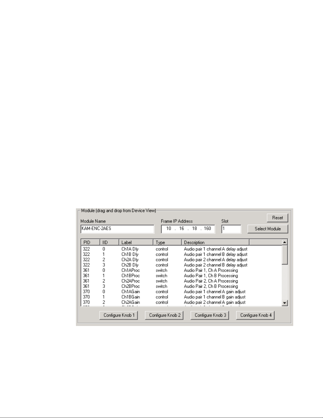
Newton Control Panel Configuration
A Newton Control Panel (hard or soft version) can be interfaced to the
Kameleon 2000 Series frame over the local network. Control panel access
offers the following considerations for module configuration and monitoring:
•Ability to separate system level tasks from operation ones, minimizing
the potential for on-air mistakes.
•Ability to group modular products—regardless of their physical locations—into logical groups (channels) that you can easily manipulate
with user-configured knobs.
•Update software for applicable modules and assign frame and panel IP
addresses with the NetConfig Networking application.
•Recommended for real-time control of module configuration parameters, providing the fastest response time.
Configuration and Adjustments
Note
An example of the Newton Configurator is shown in Figure 7.
Figure 7. Newton Configurator Example
Not all module functions are available with the control panel, such as E-MEM
and factory default recalls. The available control panel controls for the
module are listed in Table 3 on page 15.
Refer to the documentation that accompanies the Newton Modular Control
System for installation, configuration, and operation information.
KAM-ENC-2AES Instruction Manual 19
Page 20

Configuration and Adjustments
Web Browser Interface
The web browser interface provides a graphical representation of module
configuration and monitoring.
Use of the web interface offers the following considerations:
•Provides complete access to all module status and configuration func-
•Web access will require some normal network time delays for pro-
tions, including naming of inputs and outputs, factory parameter and
name default recalls, E-MEM functions, slot configuration, and SNMP
monitoring controls.
cessing of information.
•Configuration parameter changes may require pressing the
button or
become effective.
•Web interface recommended for setting up module signal and slot
names, E-MEMS, and reporting status for SNMP and monitoring.
Refer to the Frame Status page shown in Figure 8 on page 21. The Kameleon and 2000 modules can be addressed by clicking either on a specific
module icon in the frame status display or on a module name or slot
number in the link list on the left.
Note
Enter
, upload processing time, and a manual screen refresh to
The physical appearance of the menu displays on the web pages shown in
this manual represent the use of a particular platform, browser and version
of 2000NET module software. They are provided for reference only. Displays
will differ depending on the type of platform and browser you are using and
the version of the 2000NET software installed in your system. This manual
reflects 2000NET software version 3.2.2.
Apply
20 KAM-ENC-2AES Instruction Manual
Page 21

Configuration and Adjustments
Figure 8. 2000NET GUI
The Links section lists the frame and its current modules. The selected link's Status
page is first displayed and the sub-list of links for the selection is opened. The sub-list
allows you to select a particular information page for the selected device.
Content display section displays the information page
for the selected frame or module (frame slot icons are also
active links).
Refresh button for manual
update of page
8355_02
KAM-ENC-2AES Instruction Manual 21
Page 22
Configuration and Adjustments
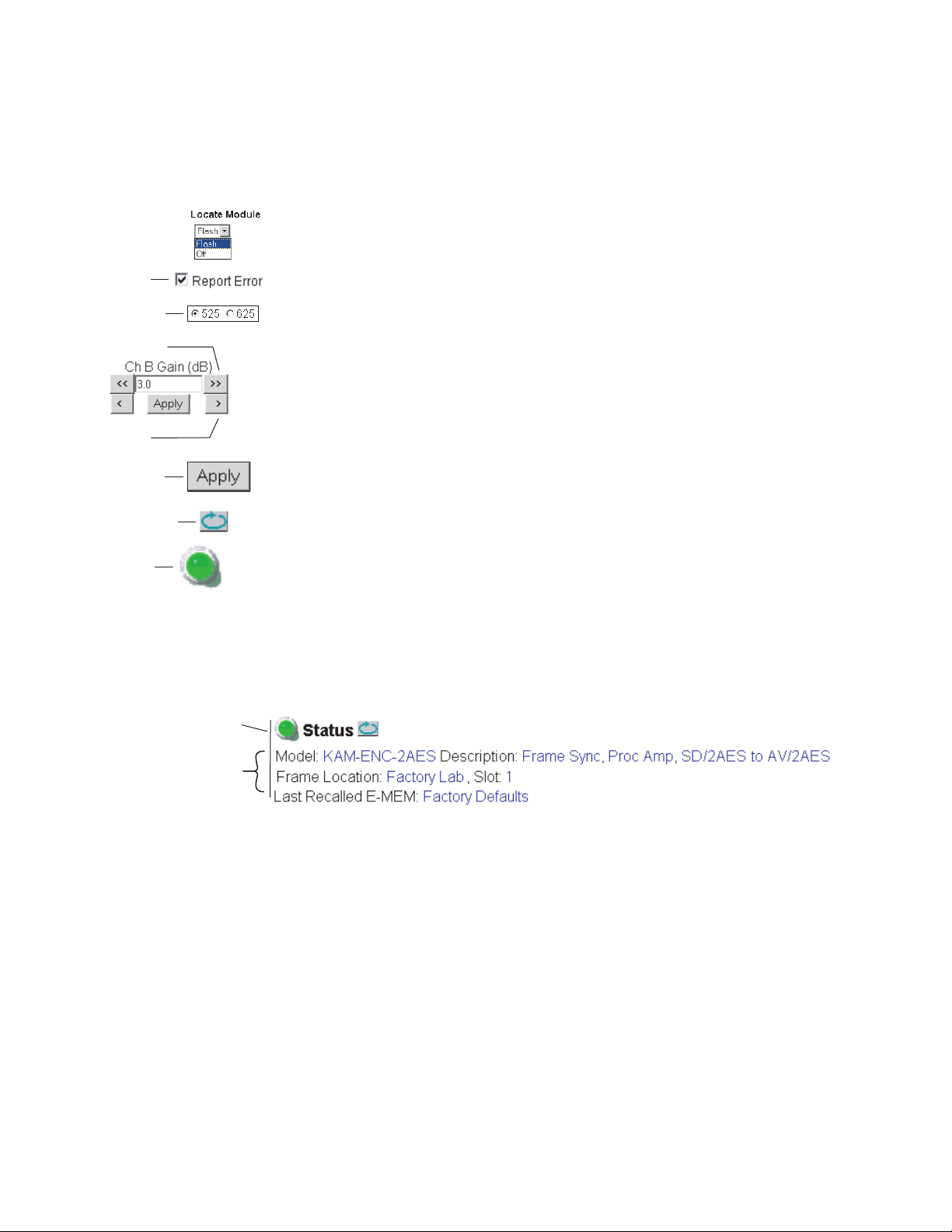
Web Page Operations and Functional Elements
The following conventions and functional elements (shown at left) are used
in Kameleon web page operations. (The examples shown throughout this
manual represent 2000NET software version 3.2.2 or later):
Pulldown Menus
Check box
Radio button
Coarse adjust
• Pulldown menus allow you to choose selections from a list.
•Check boxes are used when a selection can be enabled or included in a
•Radio buttons are used to make a choice of one parameter in a group.
• Each numerical adjustment control has a
group. Multiple check box selections or enables can be made for some
parameters.
Coarse adjust button (left and
right top double arrows) and a
Fine adjust button (left and right bottom
single arrows).
Fine adjust
Apply button
Refresh button
Status LED
•To change a value, use the arrow button controls or enter a value into
the number field and select the
number into the number field from a keyboard and hit the
apply the value.
•A
Refresh button (circular arrow) is provided for manual refresh of the
web page to view recently changed parameters.
• The Status LED is explained below.
8343_06
Status and Identification Header
Each configuration web page has a Status and Identification Header.
Figure 9. Typical Status/ID Header
Link to
Status page
Variables
Status LED icon
Apply button. You may also enter a
Enter key to
8355_03
The Status LED icon reports communication status for the frame slot and is
a link to the module Status web page where Warnings and Faults are displayed. LED colors indicate:
•Green = Pass – no problems detected
•Yellow = Configuration error warning
•Red = Fault condition detected
22 KAM-ENC-2AES Instruction Manual
Page 23

Variables:
•Model and Description are read-only generated by the module.
• Frame Location is entered in 2000 Series Kameleon Frame configura-
tion.
• Slot number reports the module’s location in the frame.
• Last Recalled E-MEM reports the last E-MEM configuration recalled
from the module.
Initial Configuration Process Overview
To configure the Kameleon module proceed as follows:
1. Go to the I/O Config web page to setup and name video and audio inputs
and outputs.
2. If not already connected, connect all input and output signals. Go to the
module
condition.
Status web page to verify component and signal presence and
Initial Configuration Process Overview
3. Go to the Video Input Select web page to configure the video source and
output timing source.
4. Go to the Functional View web page to:
•Verify the module’s functional configuration is correct, and
• Begin with the Input block links to configure each function in turn.
Note Next, Functional View, and Back links are provided to help you navigate
through a logical configuration sequence.
5. Use E-MEM memory to store or recall configurations as necessary.
KAM-ENC-2AES Instruction Manual 23
Page 24

KAM-ENC-2AES Links and Web Pages
KAM-ENC-2AES Links and Web Pages
The 2000 GUI provides the following links and web pages for the module
(Figure 10):
• Status – reports input and reference signal status and module information (page 25),
• I/O Config – shows a graphic representation of inputs and outputs to
the module and allows naming of each input (page 28),
• Functional View – shows a block diagram of the module with links to
each configuration web page (page 31),
•Module Configuration web pages for setting up the module (beginning
on page 32),
• E-MEM – provides a Standard view for Local Recall operations for up
to 5 E-MEM registers (page 56) and an Advanced view providing additional
• Slot Config – provides a Locate Module function, Slot Memory, and
SNMP trap reporting controls (page 61), and
Save to and Load from file operations (page 57),
• Software Update – allows updating of software from a CD-ROM or the
web site (page 64).
Figure 10. KAM-ENC-2AES Web Page Links
24 KAM-ENC-2AES Instruction Manual
Page 25

Status Web Page
KAM-ENC-2AES Links and Web Pages
Use
this
link
The Status web page for the KAM-ENC-2AES module (Figure 11 on
page 26) provides an overall indication of the health of the system and links
to web pages for the active components:
• Status Header – the same on all Kameleon configuration pages (see Web
Page Operations and Functional Elements on page 22),
•Color-coded communication status for each component and path,
• Summary of all fault/warning conditions, and
•Textual module status, front module, and submodule properties.
Color-coded Status Indicators and Links
Each box represents a Kameleon module or submodule as indicated in
Figure 11 on page 26. Arrows represent signal paths that may or may not
be monitored. These elements act as links when their function is active
(indicated by underlined function name).
Color code:
•Green = Pass – operating as expected.
•Yellow = Warning – signal is absent, has errors, or is misconfigured.
•Red = Fault – a component has failed.
•Grey = Not monitored.
•White = Not present.
Status/Front Module Properties
The Status/Front Module properties in the footer provide a textual
summary of the color-coded module status. Front module properties
provide hardware, firmware, software identification, and asset tag number
for the KAM-ENC-2AES module. Presence and status of any submodules
is also reported.
KAM-ENC-2AES Instruction Manual 25
Page 26

KAM-ENC-2AES Links and Web Pages
Figure 11. Module and Signal Status
Warning and Fault
summary section
26 KAM-ENC-2AES Instruction Manual
Page 27

Warning/Fault Summary
The following warnings and faults are reported in the summary section
(refer to Figure 11 on page 26). A
hibits proper operation. A
not adversely affect operating conditions, but should be noted. Usually
warnings are something the user can correct by changing configuration,
settings or input signals.
Warnings
•WARNING - Rear Module is not connected
•WARNING - Wrong Rear Module (incompatible with Kameleon)
•WARNING - Wrong Rear Module (no communication)
•WARNING - Wrong Rear Module (unknown type, incompatible)
•WARNING - Video Input is 625 and reference is 525 lines
•WARNING - Video Input is 525 and reference is 625 lines
•WARNING - Video Input is 625 but configuration is 525 lines
KAM-ENC-2AES Links and Web Pages
Fault indicates a serious condition that pro-
Warning indicates a condition which may or may
•WARNING - Video Input is 525 but configuration is 625 lines
•WARNING - Video Input Signal not detected
•WARNING - Frame Reference is not present
•WARNING - Frame Reference is not locked to input
•WARNING - Frame Reference is not present
•WARNING - No Video output - GenLock selected but not present
•WARNING - 1 or more Audio Input signals not detected
• Internal Error - Unknown sub module type
Faults
•FAULT - nnV power supply bad. (nn = variable: 24 V, 12.5 V, 5 V,
3.3 V, 1.5 V, -5 V, or -12.5 V)
•FAULT - A/D failed (A to D system measuring power supplies and bus
levels)
•FAULT - Xilinx 1 failure (main video processor)
•FAULT - Xilinx 2 failure (main audio processor)
•FAULT - MFM (Multi-function module) EEPROM checksum fails
•FAULT - DS1803 not responding (digital potentiometer for video in
adjustment)
•FAULT - TMC22051A not responding (composite input decoder)
• Internal Error - Unknown front module type
KAM-ENC-2AES Instruction Manual 27
Page 28
KAM-ENC-2AES Links and Web Pages
Input/Output Configuration Web Page
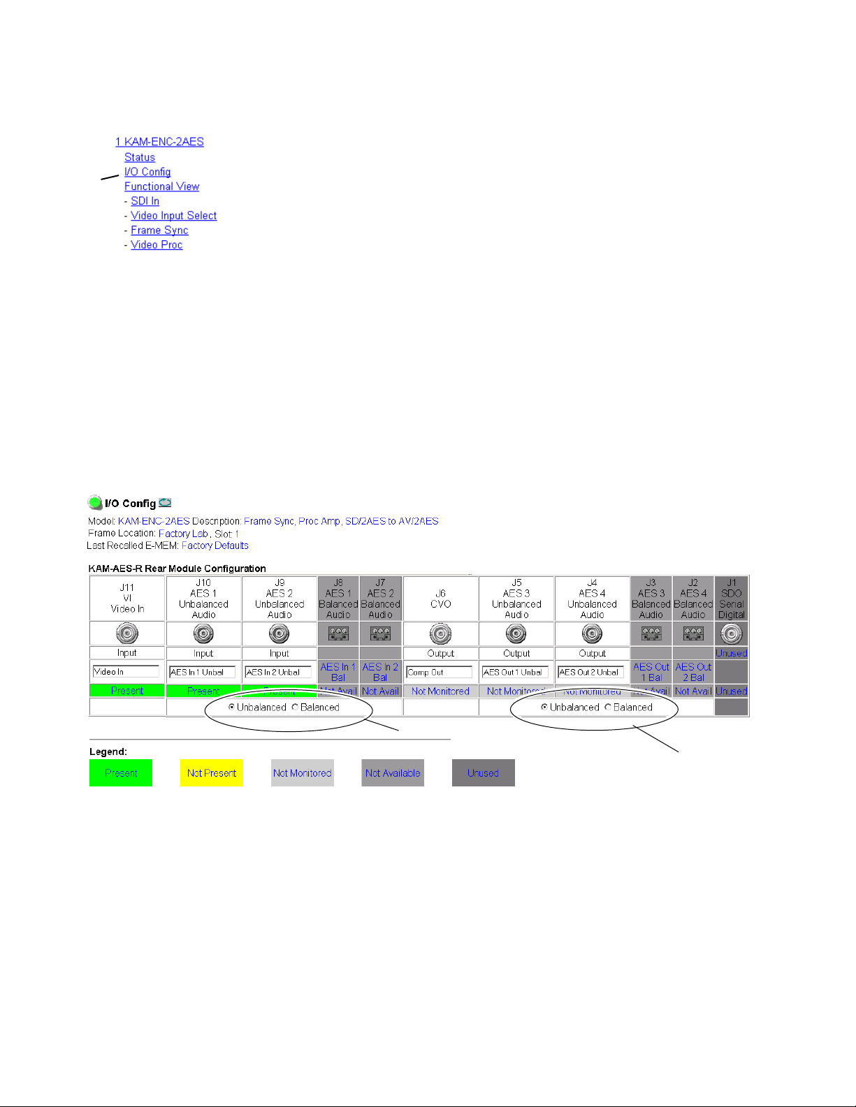
Use the I/O Config web page to:
Use
this
link
•View a graphical overview of the currently installed rear module connectors,
• See signal status of inputs,
• Set the AES audio input and output connector types with the
or
Unbalanced radio buttons, and
•Assign easily recognized signal names that will help later in the configuration process.
Figure 12 illustrates the I/O Config web page for the KAM-AES-R passive
rear module required for the KAM-ENC-2AES front module set for unbalanced AES/EBU audio inputs and outputs. Audio inputs and outputs can
be different connector types.
Note Only the selected AES outputs are valid. Unconfigured AES outputs are
invalid and should not be used.
Figure 12. KAM-AES-R Rear Module I/O Config Web Page (Unbalanced Audio)
Balanced
Select AES input type
Select AES output type
28 KAM-ENC-2AES Instruction Manual
Page 29
KAM-ENC-2AES Links and Web Pages
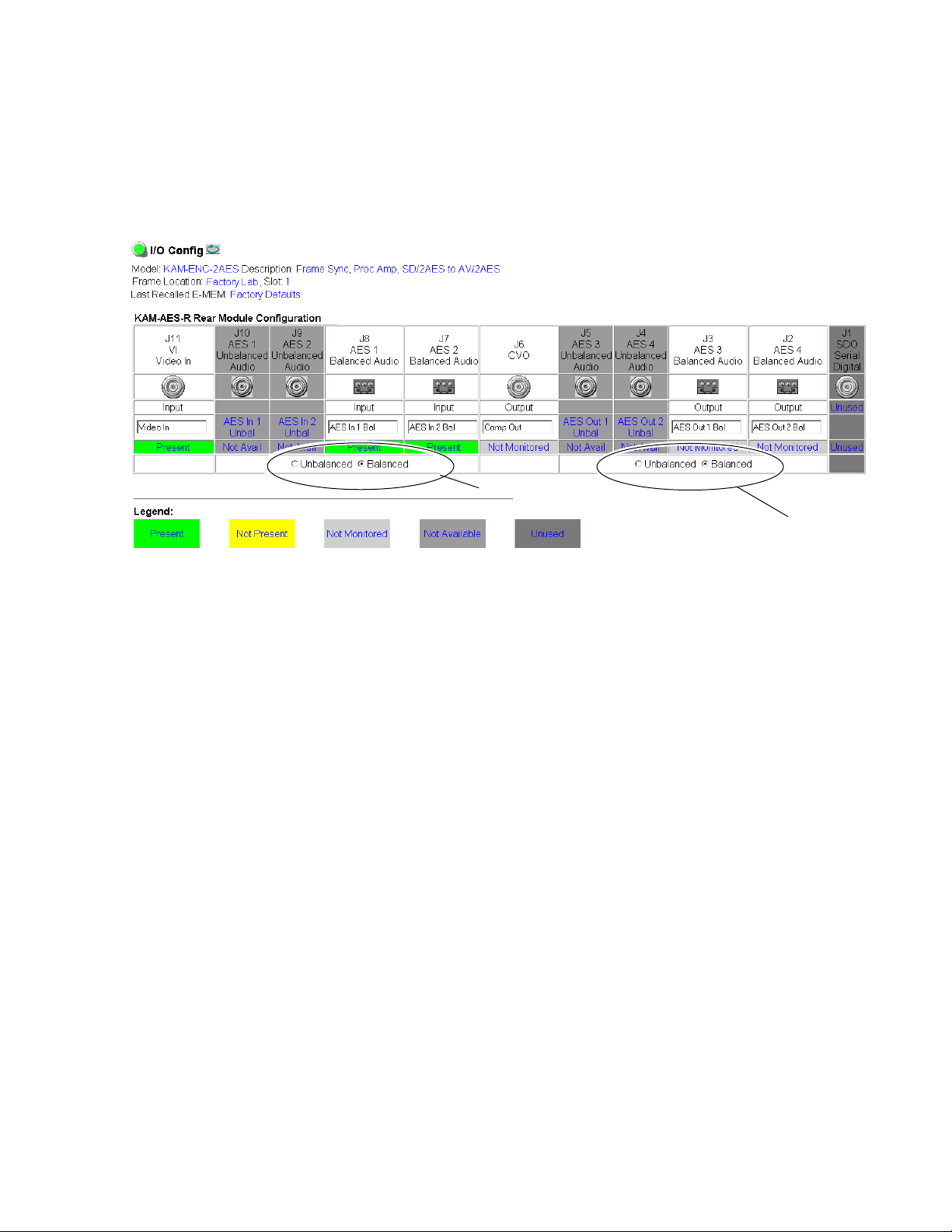
Figure 13 illustrates the I/O Config web page for the KAM-AES-R passive
rear module required for the KAM-ENC-2AES front module with the rear
module set for balanced AES audio inputs and outputs (
buttons selected).
Figure 13. KAM-AES-R Rear Module I/O Config Web Page (Balanced Audio)
Select AES input type
Balanced radio
Select AES output type
KAM-ENC-2AES Instruction Manual 29
Page 30

KAM-ENC-2AES Links and Web Pages
Header Row
The top header row provides the connector hardware physical label (J#)
and the dedicated signal type for the connector. This information is determined by the type of rear module and front processor module installed
(refer to the Functional View Web Page on page 31).
Connectors
The connector row illustrates connector type provided (BNC or 3-pin terminal) for each port. For this rear module, one SDI video input, two digital
audio outputs, and one composite video output are provided.
Input/Output Mode
I/O mode is either static read-only or an operational Input/Output selection (determined by the rear module used).
Signal Name
Enter a signal name (up to 15 characters) for each operational
input/output. The name will be used to identify the signal in other configuration web pages. Factory default names are shown in Figure 12 on
page 28 and Figure 13 on page 29.
Status
Table 4 shows, by color and signal type, the signal status reports that may
be displayed in the Status row for this module configuration:
Table 4. I/O Config Status Report Messages
Color Video In Analog Audio In Analog Audio Out Digital Audio In Digital Audio Out Video Out
Green Present None None Present None None
Yellow
Light Grey None None None None Not Monitored Not Monitored
Medium Grey None None None Not Available Not Available None
Dark Grey None None None None None None
Not present or
525/625 mismatch
None None Not Present None None
30 KAM-ENC-2AES Instruction Manual
Page 31
Use
this
link
KAM-ENC-2AES Links and Web Pages
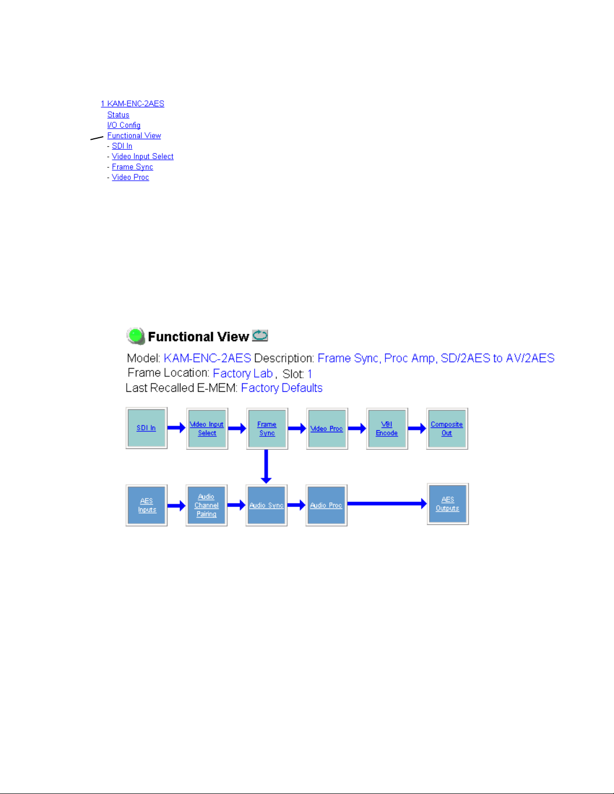
Functional View Web Page
Use the Functional View web page (Figure 14) to:
•Monitor module functions and signal paths, and
•Navigate to web pages for configuring active functions.
The Functional View web page is a block diagram of the installed Kameleon module that reports the module functions and signal paths that are
active or inactive in the current configuration. It can be used as a link map
for configuring module functions. Begin configuring with one of the input
function blocks on the left.
Color coding indicates active functions and flow. Greyed components are
inactive due to hardware and/or software constraints. Underlined module
functions are links to the web page for that function. Return links and
logical next step links are provided at the bottom of each configuration web
page.
Figure 14. Functional View Web Page
KAM-ENC-2AES Instruction Manual 31
Page 32

KAM-ENC-2AES Links and Web Pages
SDI In Web Page
Use the SDI In web page to view the status of the SDI input signal in
Summary view (Figure 15) or Detail view (Figure 16 on page 33):
Use
this
link
• Select the
in Figure 15.
•Use the
Figure 15. SDI In Web Page (Summary View)
Summary radio button to bring up the summary view shown
Clear All Status button to clear and reset the status reporting.
To view a detailed view of the SDI input status, select the Detail radio button
to bring up the view shown in Figure 16 on page 33.
This view provides input signal status for both EDH Error and Feed
Forward status. Each status report can be disabled by deselecting the corresponding
reset by selecting the corresponding
32 KAM-ENC-2AES Instruction Manual
Reporting checkbox. Each status report can also be cleared and
Clear Status button.
Page 33

Figure 16. SDI In Web Page (Detail View)
KAM-ENC-2AES Links and Web Pages
KAM-ENC-2AES Instruction Manual 33
Page 34

KAM-ENC-2AES Links and Web Pages
Video Input Select Web Page
Use the Video Input Select web page (Figure 17) to:
Use
this
link
•Configure input video line rate,
• Enable or disable Loss of Signal reporting for the input signal and
frame reference to the Status web page and SNMP monitoring (refer to
the 2000NET manual for SNMP information),
• Enable or disable the SDI Error status warning,
•Configure Vertical Blanking Interval (in Advanced mode), and
• Select the output timing reference.
Figure 17. Video Input Select Web Page – Standard View
34 KAM-ENC-2AES Instruction Manual
Page 35

View Selection
In the View Selection display, choose the Standard radio button to display
the standard settings shown in Figure 17 on page 34. Use the
for configuring the Vertical Blanking Interval for selecting active video
lines to carry data (see Advanced VBI Configuration on page 36).
Video Selection Settings
The following functions are provided in the Video Selection section in both
the Standard and Advanced views:
KAM-ENC-2AES Links and Web Pages
Advanced view
• Input Name – (read-only) signal name is entered on the
page
• Input Status –
• Signal presence reported
• Enable/disable Loss of Signal report to both Kameleon status web
pages and SNMP monitoring devices.
Note The disabling of video and reference Loss of Signal reports and SDI Input
Error warnings allow you to filter reports from higher level Kameleon status
displays and SNMP monitoring. They will still be reported on this web page.
•Video Format – current input video format reported.
•Video Line Rate – select 525 or 625 line rate or enable automatic line rate
detection
• Frame Reference –
• 2000GEN frame reference signal presence reported,
• Enable/disable Loss of Signal report to both Kameleon status web
pages and SNMP monitoring devices.
•SDI Input Errors –
I/O Config web
• Input signal errors reported, and
• Enable/disable SDI error warning report to both Kameleon status
web pages and SNMP monitoring devices.
• Frame Sync/Delay – (read-only) Frame Sync mode is reported when
Output Timing Selection is
vided from the 2000GEN module. Frame Delay mode is reported when
the input signal (
Video In) is used for timing reference.
Internal Frame Reference and timing is pro-
Output Timing Selection
The 2000GEN reference module must be installed in the frame and for the
Kameleon to work as a frame synchronizer, set the output timing source to
Internal Frame Reference. Otherwise, set the output timing source to Video In.
KAM-ENC-2AES Instruction Manual 35
Page 36

KAM-ENC-2AES Links and Web Pages
Advanced VBI Configuration
Advanced VBI configuration allows you extend VBI into the active picture
range for special data insertion requirements. Active video lines that are
used to carry data are referred to as Data Lines.
To add Data Lines to VBI:
1. Choose Advanced (VBI Config) on the Video Input Select web page
(Figure 18).
Figure 18. Standard and Advanced View Selection
The VBI/Data Lines panel will appear at the bottom of the web page (see
Figure 19 on page 37 for 525 line rate and Figure 20 on page 37 for 625
line rate).
2. Select the last line (includes all previous active video lines) that will be
used for data.
Selected active video lines will be shown in the
the web page as shown for lines 21/284 and 22/285 in Figure 19 and lines
24/337 and 25/338 in Figure 20. Lines not reserved for data will be greyed
out on the VBI Decode web page (VBI Encode For Composite Output on
page 44).
Active video lines that can be made available for data insertion are:
• For 525, lines 21 – 24 in Field 1, lines 284 – 287 in Field 2
• For 625, lines 24 – 28 in Field 1, lines 337 – 341 in Field 2
Reserved for Data section of
36 KAM-ENC-2AES Instruction Manual
Page 37

KAM-ENC-2AES Links and Web Pages
Figure 19. Advanced VBI Configuration – 525 Line Rate
Figure 20. Advanced VBI Configuration – 625 Line Rate
KAM-ENC-2AES Instruction Manual 37
Page 38

KAM-ENC-2AES Links and Web Pages
Frame Sync Web Page
Use the Frame Sync web pages (Figure 22 and Figure 21 on page 39) to:
•Adjust horizontal and vertical timing, and
Use
this
link
Timing Adjustment
Freeze Mode Selection
•Freeze the current output or, if using a 2000GEN reference signal, select
an automatic freeze mode for output when the signal is lost.
Table 5 shows the ranges of timing for 525 and 625 signal formats.
Table 5. Timing Adjustment Ranges
Line Rate Max Horizontal Adjustment Max Vertical Adjustment
525/NTSC 857.5 pixels 524 lines
625/PAL 863.5 pixels 624 lines
The Freeze mode controls available depend on the output timing reference
selected on the Video Input Select Web Page on page 34.
When set to Frame Delay mode (using the
Freeze Mode allows you to manually freeze the output using
or one
and no motion artifacts in the output. In Frame mode the resolution is
higher since both fields are present, but the presentation of two fields can
cause motion artifacts.
Frame Sync mode (using the 2000GEN Internal Frame Reference as the output
timing reference) provides the manual selections plus
reeze modes used when the video signal is lost (Figure 21 on page 39).
AutoBlack outputs a black signal and AutoFreeze outputs the last complete
video field.
Frame (Figure 22 on page 39). A field freeze provides less resolution
Video In output timing reference),
Field 1, Field 2,
AutoBlack and AutoF-
38 KAM-ENC-2AES Instruction Manual
Page 39

KAM-ENC-2AES Links and Web Pages
Figure 21. Frame Synchronizer Web Page – Video In Reference
Figure 22. Frame Synchronizer Web Page – Frame Sync Reference
KAM-ENC-2AES Instruction Manual 39
Page 40

KAM-ENC-2AES Links and Web Pages
Video Processing Web Page
Use the Video Proc web page to:
• Enable/disable Standard or Advanced video processing,
Use
this
link
•Turn on Color Bars test signal,
• Enable/disable video gain lock,
•Adjust component video gain (Y, B-Y, R-Y),
•Adjust component video DC Offset (Y, B-Y, R-Y),
• Enable/disable soft and hard clipping controls, and
•Apply selected clip settings to VBI.
Video Processing Controls
Video Processing Enable
To bypass Video Processing on the SDI signal select Disable (Figure 23 on
page 41). To make video processing adjustments to the SDI signal select
Enable or select Color Bars to use the internally generated 100% vertical color
bars test signal.
Two modes of video processing are available, Standard or Advanced. With
Standard selected, only the Y Channel Video Processing controls on the left
will be visible along with the clipping controls.
When
trols will also be displayed as shown in Figure 24 on page 43.
Advanced is selected, the B-Y and R-Y Gain and Balance/Offset con-
Standard View
In Standard View (Figure 23 on page 41), adjust the following for the
Y Channel:
•Contrast/Y Gain – adjust the percentage of luminance relative to white
(50 to 149.6%).
• Saturation/Chroma Gain – adjust the percentage of saturation and
chroma gain relative to 100% saturation (50 to 149.6%).
• Brightness/Y Offset – adjust the amount of brightness/Y offset in mV
(-3.55 to 3.44%)
•Hue/Chroma Phase – adjust the hue/chroma phase in degrees (-89.8 to
89.8 degrees).
40 KAM-ENC-2AES Instruction Manual
Page 41

KAM-ENC-2AES Links and Web Pages
Figure 23. Video Processing Web Page – Standard View
KAM-ENC-2AES Instruction Manual 41
Page 42

KAM-ENC-2AES Links and Web Pages
Advanced View
In Advanced View (Figure 24 on page 43), adjust the following for the B-Y
and R-Y Channels:
Note To adjust gain for all channels simultaneously, set Video Gain Lock to On.
This locks Y, B-Y, and R-Y adjustments together. Adjustment of one gain
setting changes all gain values (Y, B-Y, R-Y) the same amount.
• B-Y/R-Y Gain – adjust the percentage of B-Y and R-Y gain relative to
100% (50 to 149.6%).
• B-Y/R-Y Balance/Offset – adjust the amount of B-Y and R-Y DC offset
in mV (-3.55 to 3.44%)
Clipping Controls
Clipping controls are provided that affect the luminance (soft/Y) and
overall saturation (hard/video) levels of the output signal.
Refer to Figure 24 on page 43. To enable the clip controls select the
radio button. You may also apply the clip levels to the vertical blanking
interval by checking the
Use the following clipping controls to adjust levels on the composite
output:
•Use the
(white) of the luminance signal (positive excursions).
•Use the
end (black) of the luminance signal (negative spikes and Super Black).
•Use the
end (white) of the overall video signal (clips white and reduces overall
saturation level to fit within clip).
•Use the
bottom end (black) of the overall video signal (clips black and reduces
overall saturation level to fit within clip).
Reset To Default
Select the Reset To Default button on the bottom of the screen to return all
values to the factory defaults.
Enable
Apply clips to VBI box.
Soft/Y White Clip control to set the clipping level for the top end
Soft/Y Black Clip control to set the clipping level for the bottom
Hard/Video White Clip control to set the clipping level for the top
Hard/Video Black Clip control to set the clipping level for the
42 KAM-ENC-2AES Instruction Manual
Page 43

KAM-ENC-2AES Links and Web Pages
Figure 24. Video Processing Web Page – Advanced View
KAM-ENC-2AES Instruction Manual 43
Page 44

KAM-ENC-2AES Links and Web Pages
VBI Encode For Composite Output
Use the VBI Encode web page (Figure 25 for 525, Figure 26 on page 45 for
625 line rate) to configure the VBI and Data Line encoding for the composite output signal.
Use
this
link
The currently detected line rate will be reported. Use the View Selection to
view the web page at the correct line rate with the
This web page allows you to do the following on a line-by-line basis:
•Remove black level setup (in NTSC or PAL-M video)
• Blank existing VBI and Data Line information
525 or 625 radio button.
You may also apply clips to all VBI lines by checking the
checkbox.
Note The data lines not reserved for carrying data on the Video Input Select web
page will appear greyed out. See Advanced VBI Configuration on page 36.
Figure 25. VBI Encode Web Page – 525 Line Rate
Apply clips to VBI
44 KAM-ENC-2AES Instruction Manual
Page 45

Figure 26. VBI Encode Web Page – 625 Line Rate
KAM-ENC-2AES Links and Web Pages
KAM-ENC-2AES Instruction Manual 45
Page 46

KAM-ENC-2AES Links and Web Pages
Composite Out Web Page
Use the Composite Out web page (Figure 27 on page 47 for calibrated
adjustment and Figure 28 on page 48 for user adjustment) to set parameters
for the composite video output on the module as listed below:
Use
this
link
Output Video Adjustments
• Select the
525 composite outputs,
• Enable or disable the following by selecting the corresponding radio
button:
•
Cross Color Removal– enabling this control filters our unwanted lumi-
nance and chrominance artifacts produced during encoding.
•
Chrominance Signal – enable this control to completely remove the
chrominance portion of the composite output signal.
•
Burst Signal – enable this control to completely remove the burst
portion of the composite output signal.
Setup or No Setup radio button to add or not add setup on the
The following output video adjustments can be made for gain and
coarse/fine delay of the composite output signal when the
button is selected (Figure 27 on page 47). The delay settings are independent of the Frame Sync controls.
•
Delay Coarse – adjusts the output delay in coarse steps of 5 pixels (double
arrows) or 0.5 pixels (single arrows). The coarse delay range is from 0 to
4095 pixels.
•
Delay Fine – adjusts the percent of output delay in fine steps of 10 percent
(double arrows) o r1.0 percent (single arrows). The fine delay range is
from 0 to 100% (100% = 37-38 ns)
•
Output Video Gain – adjusts the output video gain in steps of 5 percent
(double arrows) or 0.5 percent (single arrows). The output gain range is
approximately 61to 138.5 percent.
Calibrated radio
46 KAM-ENC-2AES Instruction Manual
Page 47
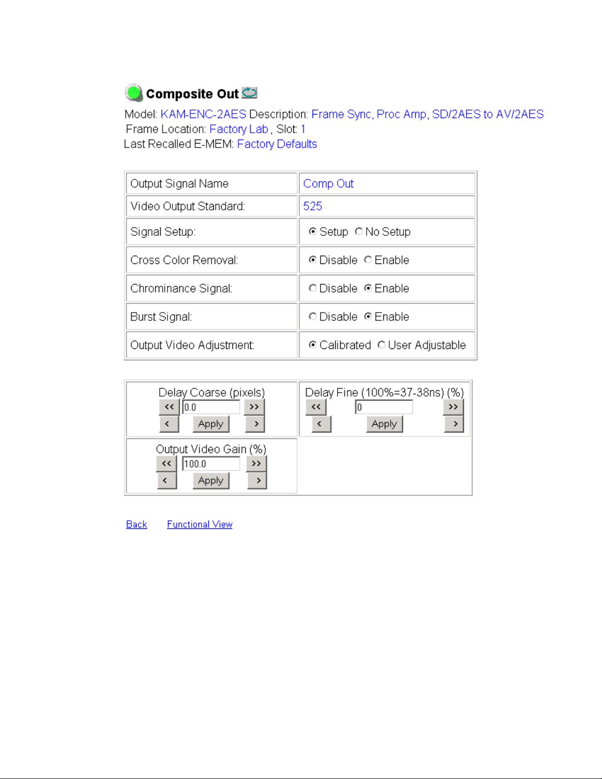
Figure 27. Composite Out Web Page (Calibrated)
KAM-ENC-2AES Links and Web Pages
KAM-ENC-2AES Instruction Manual 47
Page 48

KAM-ENC-2AES Links and Web Pages
When the User Adjustable radio button is selected the following controls are
also made available for adjustment of the composite output (Figure 28):
• Luma Gain – adjust percentage of luma (brightness) relative to 100%.
•Chroma Gain – adjust the percentage of color saturation relative to
100%.
• Black Level – adjust the percentage of black level relative to 0%.
•Hue – (control appears in 525 only) adjust the hue of the output signal
in degrees.
Figure 28. Composite Out Web Page (User Adjustments)
User Adjustments
48 KAM-ENC-2AES Instruction Manual
Page 49

Use
this
link
AES Inputs Web Page
Use the AES Inputs web page (Figure 29) to check the status of the AES
audio inputs. The following information is reported for each input:
•
AES Input characteristics – reports the audio characteristics for input J9 and
J10 as shown in the table. Use the
tion.
•
Audio Stream Input reporting – allows the user to enable or disable the fol-
lowing reporting items with the corresponding checkbox:
• Sample Rate Conversion
• Loss of Signal (to both Kameleon Status web page and SNMP monitoring devices)
•AES Errors
Figure 29. AES Inputs Web Page
KAM-ENC-2AES Links and Web Pages
Clear button to reset the error detec-
KAM-ENC-2AES Instruction Manual 49
Page 50

KAM-ENC-2AES Links and Web Pages
Audio Channel Pairing Web Page
The Audio Channel Pairing web page (Figure 30) allows the input audio
streams to be arbitrarily recombined into new pairs and swapped or set to
Silence. The rows represent the audio input streams and the columns repre-
Use
this
link
sent the audio output channels. The columns are grouped together into two
different digital audio pairs (Pair 1 Ch A and Ch B and Pair 2 Ch A and
Ch B).
The audio streams in the group are paired on the Audio Channel pairing
web page. The pairs (Pair 1 Ch A and Ch B and Pair 2 Ch A and Ch B) can
be output on the balanced or unbalanced AES audio output connectors on
the KAM-AES-R rear module (see
page 28
Note Audio output names are assigned using the I/O Config web page.
Figure 30. Audio Channel Pairing Web Page
).
Input/Output Configuration Web Page on
50 KAM-ENC-2AES Instruction Manual
Page 51

Audio Sync Web Page
Use the Audio Sync web page (Figure 31 on page 52) to:
KAM-ENC-2AES Links and Web Pages
Use
this
link
• Synchronize the two audio channel pairs to video Frame Sync, and/or
•Add audio delay using the delay adjust controls to add delay to each
channel or lock the channels together as a pair and adjust delay.
Enable Auto Track
Select the On checkbox to enable auto tracking to synchronize the audio pair
to the video frame sync. The amount of auto tracking applied is shown in
the Auto Tracking Delay read-only display.
The total amount of delay is reported in the Total Delay read-only display
for each channel.
Delay Adjustments
Each audio channel can be adjusted for delay separately or in pairs. Use the
following adjustments for audio delay:
•To lock the two channels in a pair together, select the
checkbox for Pair 1 or Pair 2.
•Adjust the delay for each channel with the Ch A Delay Adjust and Ch B
Delay adjust controls for each pair. If the pair is locked, adjusting either
control will set the delay to the same value for each channel in the pair.
Channel Lock
KAM-ENC-2AES Instruction Manual 51
Page 52

KAM-ENC-2AES Links and Web Pages
Figure 31. Audio Sync Web Page
52 KAM-ENC-2AES Instruction Manual
Page 53

Audio Processing Web Page
Use the Audio Proc web page (Figure 32 on page 54) to adjust the following
for each audio pair:
KAM-ENC-2AES Links and Web Pages
Use
this
link
•Adjust
• Lock gain settings for simultaneous channel A/channel B adjustment,
• Select a processing option for each channel, and
• Select output resolution for each output pair.
Audio Gain
Each audio channel can be adjusted for gain separately or in pairs. Use the
following adjustments for audio gain:
•To lock the two channels in a pair together, select the Gain Settings
•Adjust the gain (-40 to +6 dB) for each channel with the Ch A Gain
Note After gain has been adjusted, a straight quote mark (') will be added to Ch A'
audio signal gain for each individual channel or the two audio
pairs,
Locked checkbox for Pair 1 and/or Pair 2.
Adjust and Ch B Gain adjust controls for each pair. If the pair is locked,
adjusting either control will set the gain to the same value for each
channel in the pair.
and Ch B' to indicate the status of the channels after gain.
Output Processing
Set the output processing for each channel with the Processing pulldown
to one of the following:
• Pass
• Invert
•A+B
•A-B
• -(A+B)
•1 kHz (test tone)
• 400 Hz (test tone)
• Silence
The Presence and Clipping status of each audio channel is reported as
or
False in the read-only displays. If the audio is > -40 dBFS, it will be
reported as
shown in Figure 32 on page 54.
True
True. If clipping is < 0.5 dBFS, it will be reported as False as
KAM-ENC-2AES Instruction Manual 53
Page 54

KAM-ENC-2AES Links and Web Pages
Selecting Output Resolution
Select the AES output resolution for Pair 1 and Pair 2 with the 20 bit or 24 bit
radio button.
Figure 32. Audio Processing Web Page
54 KAM-ENC-2AES Instruction Manual
Page 55

Use
this
link
KAM-ENC-2AES Links and Web Pages
AES Outputs Web Page
Use the AES Outputs web page (Figure 33) to do the following:
• Select audio pairs for output to the assigned audio connectors (refer to
Input/Output Configuration Web Page on page 28 for connector informa-
tion and audio signal name assignment).
• Status reporting on this page will show the following:
•Whether
Input/Output Configuration Web Page on page 28),
•Output Sample Rate for the AES outputs,
•Output resolution as selected on the Audio Processing Web Page on
page 53. A link to this page is provided.
Figure 33. AES Outputs Web Page
Unbalanced or Balanced audio outputs are enabled (set on
KAM-ENC-2AES Instruction Manual 55
Page 56

KAM-ENC-2AES Links and Web Pages
E-MEM Configuration Web Page
The E-MEM page provides local operations for learning and recalling configurations into five E-MEM registers. File operations are also available for
saving or loading the learned E-MEM files to and from a hard disk or other
Use
this
link
accessible media.
Factory default settings for all channels can be recalled by selecting the
Recall factory settings button. To return the module to the factory signal
names (such as the signal inputs), select the
Recall factory names button.
There are two E-MEM view selections:
In Standard view (Figure 34), any one of five learned E-MEMs can be
recalled by selecting the corresponding
tions window. This will place the configuration for the entire module into
that E-MEM into the KAM-ENC-2AES. This change will occur immediately
upon recall. The name of the last recalled E-MEM will appear in the top
header of each web page for the module.
To learn an E-MEM select the
This will open the Advanced view (Figure 35 on page 57).
Figure 34. E-MEM Web Page (Standard View)
Advanced button in the View Selection section.
Standard and Advanced.
Recall button in the Local Opera-
56 KAM-ENC-2AES Instruction Manual
Page 57

KAM-ENC-2AES Links and Web Pages
The Advanced View (Figure 35) includes a File Operations section to learn
a configuration into E-MEM (
or load a file from a disk location (
To learn an E-MEM:
1. Open the Advanced view.
2. When the configuration is complete for all channels on the module,
type a descriptive name for the configuration into an unused E-MEM
register (or overwrite an existing one).
3. Learn the E-MEM to memory by selecting the corresponding Learn
button. All channel configurations are learned at once and stored in the
same register. This register is now learned and ready for recall.
Figure 35. E-MEM Web Page (Advanced View)
Learn), save a file to a disk location (Save to...)
Load from...).
KAM-ENC-2AES Instruction Manual 57
Page 58

KAM-ENC-2AES Links and Web Pages
File Operations
Save File
File operations allow you to save learned configurations to a computer
hard drive or other accessible media for later recall to the onboard E-MEM
registers of any Kameleon module in your system.
To save to a file, first make sure you have learned the configuration, then
press the
Save To... button.
This will bring up a File Download screen similar to Figure 36. Select
Figure 36. File Download Screen
Save.
58 KAM-ENC-2AES Instruction Manual
Page 59

KAM-ENC-2AES Links and Web Pages
This will bring up the Save As screen as shown in Figure 37. Locate or
create a directory for storing the E-MEMs and select
ister is now saved to the selected location and may be recalled as described
below.
Figure 37. Save As Screen
Save. This E-MEM reg-
Load File
A file may be loaded from a saved directory to a register on the E-MEM
web page by selecting the
ister in the Advanced view. This will bring up the Load E-MEM web page
(Figure 38).
Figure 38. Load E-MEM Web Page
Load From... button in the associated E-MEM reg-
KAM-ENC-2AES Instruction Manual 59
Page 60
KAM-ENC-2AES Links and Web Pages
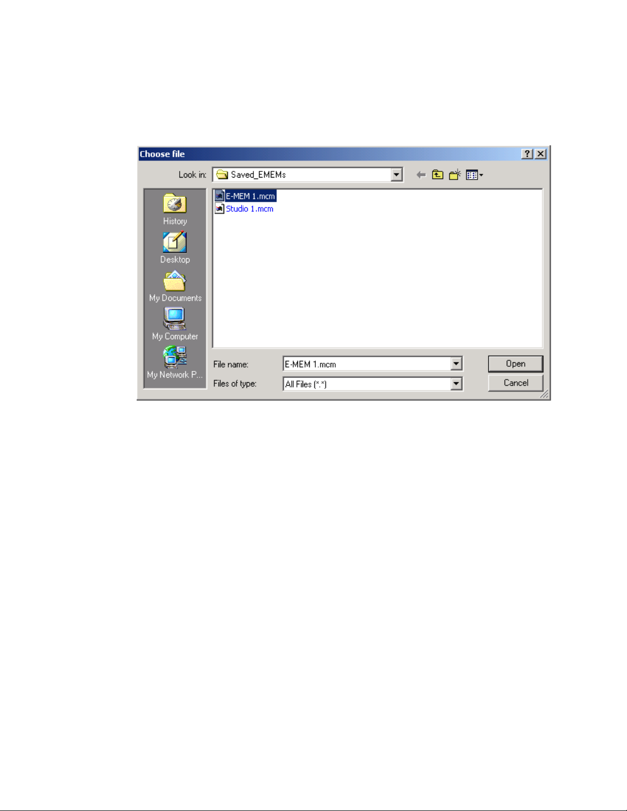
Enter a path and filename or use the Browse button to locate your saved
E-MEM files. Browse to the Choose File screen (Figure 39), select the
E-MEM file to download and select
Figure 39. Choose File Screen
Open.
This will place the path and filename in the Load E-MEM screen (Figure 38
on page 59). If this is the correct file, select
select
Cancel to return to the main E-MEM web page. Loaded files will now
be entered in the associated E-MEM registers.
Select the associated
figuration to the module.
Recall button for each E-MEM register to load the con-
Load. Continue to load files or
60 KAM-ENC-2AES Instruction Manual
Page 61

Slot Configuration
Use the Slot Config web page (Figure 40 on page 62) to:
•Assign an appropriate name to the module slot,
•Assign an Asset Tag identification,
KAM-ENC-2AES Links and Web Pages
Use
this
link
• Enable/disable the
• Save module configuration and enable slot memory,
•Check SNMP related 2000NET module switch settings, and
• Enable/disable SNMP reporting for the specific Kameleon slot.
Slot Identification
You may identify the module by typing a specific name in the Name field.
The assigned name is stored on the 2000NET module and travels with the
2000NET module if it is moved to another frame. Select
factory default module name.
An asset identification may be entered in the
on the module Status web page and in the NetConfig inventory report.
Locate Module
When enabled by selecting the Flash pulldown, the Locate Module function
flashes the yellow COMM and CONF LEDs on the front of the module to
make it easy to locate in the frame (see Operation Indicator LEDs on page 14).
Locate Module function,
Default to enter the
Asset Tag field. This will appear
Slot Memory
The slot configuration for each media module is automatically saved periodically to the 2000NET module in that frame. You may also select the
Module Config button at any time to save the current configuration for this
slot. The configuration is saved on the 2000NET module. If the 2000NET
module is removed or powered down, the stored configurations are not
saved.
When the
saved to this slot is saved as slot memory. When the current module is
removed and another module of the same type is installed, the configuration saved to the 2000NET module will be downloaded to the new module.
The box must be checked before the current module with the saved configuration is removed.
Learn
Restore upon Install box has been checked, the current configuration
KAM-ENC-2AES Instruction Manual 61
Page 62

KAM-ENC-2AES Links and Web Pages
Figure 40. Slot Configuration Web Page
62 KAM-ENC-2AES Instruction Manual
Page 63

Frame Heath Reporting
The reporting of Slot Fault, Signal Loss, and Reference Loss can be enabled
or disabled to the Frame Health connector on the rear of the Kameleon
frame by selecting or deselecting the corresponding checkbox.
Hardware Switch Controls
This section is a read-only status report of 2000NET module switch settings
for Module Status Reporting and Asynchronous Status Reporting. These
functions must be enabled for the following Slot SNMP Trap Reports to
function.
Slot SNMP Trap Reports
This section is displayed only when the SNMP Agent software has been
installed on the 2000NET module (refer to the 2000NET Instruction Manual
for installation instructions). Slot SNMP traps can be enabled only when
the hardware switches for Module Fault reporting and Asynchronous
Status reporting are enabled on the 2000NET module (dipswitch S1
segment 7 and dipswitch S2 segment 1).
KAM-ENC-2AES Links and Web Pages
The enabled SNMP traps will be reported to any SNMP manager that is
identified as an SNMP Report Destination in 2000NET configuration. Trap
severity is read-only hard-coded information that is interpreted and
responded to by the SNMP Manager software configuration.
KAM-ENC-2AES Instruction Manual 63
Page 64

KAM-ENC-2AES Links and Web Pages
Software Update Web Page
The Software Update web page (Figure 41) allows you to download new
software versions for the module using the FTP server method described in
Use
this
link
the 2000NET Instruction Manual available on-line.
Software may also be updated using the NetConfig Networking Application PC option available with Modular and other Grass Valley products as
described in the documentation that accompanies the option.
Refer to the latest module Release Notes for complete details on how to
obtain and install the latest software for this module.
Figure 41. Software Update Web Page
64 KAM-ENC-2AES Instruction Manual
Page 65

Specifications
Specifications
Note Specifications are subject to change without notice.
Table 6. SDI Input Specifications
Parameter Value
SDI Input
Signal type Serial digital video conforming to SMPTE259M 10-bit 4:2:2component
digital signal
Input impedance 75 Ω
Connector type 75 Ω BNC on rear module
Input return loss > 15 dB to 270 MHz
Common mode rejection ratio 2 V p-p to 60 Hz
Equalization Up to 250 meters of Belden 1694A
Table 7. Composite Output Specifications
Parameter Value
Composite output
Number of outputs 1
Signal type Composite analog video conforming to SMPTE170M for NTSC and
CCIR624 for PAL-B
Signal level 600 mV to 1.4 V p-p adjustable, 1 V p-p default
Output clamping level 0 VDC ± 20 mV
Output impedance 75 Ω
Connector type 75 Ω BNC on rear module
Output return loss > 40 dB to 5.5 MHz
Output isolation > 46 dB to 5.5 MHz
Composite Output Performance
Response ± 0.1 dB to 5.0 MHz
Differential phase < 0.5 degrees
Differential gain < 0.9%
Group delay < 10 ns to 5.5 MHz
RMS signal-to-noise > 59 dB to 5.5 MHz
Resolution 10 bits
Accuracy 9.2 bits
Subcarrier jitter < 1 degree when input clock jitter spec is met
Blanking start/end SMPTE170M or CCIR624, non-adjustable
Composite Output Control Parameters
Overall video gain 61% to 138% in 0.5% steps, 100% default
Black range -7.5% to +15% of luma full-scale in 0.1% steps, 0 default
Luma gain 50 – 150% in 1% steps, 100% default
KAM-ENC-2AES Instruction Manual 65
Page 66

Specifications
Table 7. Composite Output Specifications - (continued)
Parameter Value
Chroma gain 50 – 150% in 1% steps, 100% default
Hue range ± 22.5 degree 0.5 degree steps, 0 degree default (525 only)
Setup processing in vertical Line by line on/off (525 only)
Vertical blanking processing Line by line blank/unblank
Prefiltering Cross-color & luma reduction 2D filtering on/off
Table 8. Frame Sync/Timing Specifications
Parameter Value
Video Frame Sync Timing Control Parameters
Delay adjustment (main) 0 to 1 frame in 37 ns steps
Additional delay, composite out 0 to 151µs in 37 ns steps
Fine phase delay, composite out 0 to 37 ns in 100 steps
Table 9. Main Video Processing Specifications
Parameter Value
Main Video Frame Processing Control Parameters
Y gain ± 50% in 0.4% steps, 100% default
Y offset ± 3.5% of 100% white in 0.11% steps, 0% default
B-Y gain ± 50% in 0.4% steps, 100% default
B-Y offset ± 3.5% of 100% white in 0.11% steps, 0% default
R-Y gain ± 50% in 0.4% steps, 100% default
R-Y offset ± 3.5% of 100% white in 0.11% steps, 0% default
Color bars On/off
Table 10. AES/EBU Input Specifications
Parameter Value
AES/EBU Input Balanced (AES3-1992) Unbalanced (AES3id 2001)
Common mode range + 10/-10 V, 50 Hz to 20 kHz NA
Differential voltage range 200 mV p-p to 12 V p-p 200 mV p-p to 2 V p-p
Input return loss > 25 dB (100 kHz to 6 MHz) >15 dB (100 kHz to 6 MHz)
Sample rate 32 – 96 kHz 32 – 96 kHz
Performance
Static withstand 5 kV (330 Ω, 150 pF)
66 KAM-ENC-2AES Instruction Manual
Page 67

Specifications
Table 11. AES/EBU Output Specifications
Parameter Value
AES/EBU Output Balanced (AES3-1992) Unbalanced (AES3id 2001)
Signal type AES3 1992, 110 Ω AES3id 2001, 75 Ω
Signal level 3 V p-p ±0.2 V @ 110 Ω 1 V p-p ±0.2 V @ 75 Ω
Rise/fall time 5 ns to 30 ns, 110 Ω load 37 ns ± 7 ns, 75 Ω load
Output return loss > 25 dB (100 kHz to 6 MHz) >15 dB (100 kHz to 6 MHz)
DC offset < 50 mV < 50 mV
Sample rate 48 kHz 48 kHz
Bits/sample 20/24 bits/sample, selectable 20/24 bits/sample, selectable
AES/EBU Performance
Static withstand 5 kV (330 Ω, 150 pF)
Table 12. Audio Processing Specifications
Parameter Value
Audio Processing
Number of channels supported 4
Sample Rate Conversion All audio inputs retimed to output timing reference (either input video
or frame reference)
Fixed Delay 0 – 5.2 sec in 20 ms steps, individual setting for each channel
Delay Tracking Delay can be set to automatically track delay through video frame sync
with fixed offset
Gain +6 to -40dB in 0.1dB steps, individual setting for each channel.
Other processing Selectable: Invert; L + R; L-R; -(L-R); 1 kHz; 400 Hz; Silence
Individual setting for each channel.
Re-pairing Complete flexibility to swap or recombine any input channel with any
other
Table 13. Electrical Length Specifications
Parameter Value
Electrical Length
SDI In to Composite Out 1 line + 16 µs
SDI In to AES/EBU Out 3.8 ms
AES/EBU to AES/EBU 2.0 ms @ 48 KHz
KAM-ENC-2AES Instruction Manual 67
Page 68

Specifications
Table 14. Environmental/Power Specifications
Parameter Value
Environmental
Frame temperature range 0 to 40 degrees C ambient
Operating humidity range 0 to 90% non-condensing
Non-operating temperature -10 to +70 degrees C
Mechanical
Frame type 2000T1DNG Kameleon Frame or 2000T3NG Kameleon Frame
Power
Consumption 14 Watts
68 KAM-ENC-2AES Instruction Manual
Page 69

Service
Troubleshooting
Service
The Kameleon modules make extensive use of surface-mount technology
and programmed parts to achieve compact size and adherence to
demanding technical specifications. Circuit modules should not be serviced in the field except to check and replace fuses.
If your module is not operating correctly, proceed as follows:
•Check frame and module power at the front edge testpoints (Figure 42).
• If power is not present, check the fuse on the +24 V input (Figure 42).
•Check for presence and quality of input signals.
•Verify that source equipment is operating correctly.
•Check cable connections.
J12
Voltage
Tes t Points
J12
+15V
+5V
+3.3V
+1.5V
-5V
-15V
Figure 42. Location of Module Fuse and Voltage Testpoints
8345_05
Fuse F1, 2A 125 V
Refer to Figure 6 on page 13 for the location of PWR LED and Table 2 on
page 14 for proper LED indications.
If the module is still not operating correctly, replace it with a known good
spare and return the faulty module to a designated Grass Valley repair
depot. Call your Grass Valley representative for depot location.
Refer to the Contacting Grass Valley at the front of this document for the
Grass Valley Customer Support Information number.
KAM-ENC-2AES Instruction Manual 69
Page 70

Service
70 KAM-ENC-2AES Instruction Manual
Page 71

Index
Numerics
2000GEN module
for output timing
requirement 8
2000NET module
hardware requirements
software requirement 8
A
AES audio inputs 49
AES errors 49
cabling 12
configuring connectors 28
selecting connector type 15
status reporting 49
AES audio outputs
cabling
connections 28
selecting connector type 15
selecting connector typeconfiguring
specifications 67
web page control 55
AES Inputs web page 49
AES Outputs web page 55
Apply button 22
Asset Tag
assigning
Status web page 25
audio
channel lock
channel pairing
channel swap
delay
12
connectors
61
summary table
web page control 51
summary table
web page controls 50
summary table
web page control 50
channel locking
35
28
18
17
17
17, 51
7
summary table 17
web page control 51
gain
summary table
web page controls 53
output resolution
summary table
web page control 54
processing
specifications
summary table 18
web page controls 53
silence 50
Audio Channel Pairing web page 50
Audio Proc web page 53
Audio Sync web page 51
auto tracking (audio)
summary table
web page control 51
18
18
67
17
B
balanced audio outputs
cabling
configuring connectors
black level (composite out)
summary table
web page control 48
burst signal (composite out)
summary table
web page control 46
B-Y gain
summary table
web page control 42
B-Y offset
summary table
web page control 42
12
balanced audio inputs
configuring connectors 29
17
17
16
16
KAM-ENC-2AES Instruction Manual 71
Page 72

Index
C
chroma gain (composite out)
summary table
web page control 48
chroma gain (saturation)
summary table
web page control 40
chrominance signal (composite out)
summary table
web page control 46
clipping
apply to VBI
audio status 53
video 42
clipping controls
summary table
Coarse adjust button 22
coarse delay (composite out)
summary table
web page control 46
color code
Functional View web page
COMM LED 14
compatible network software 7
Composite Out web page 46
composite video out
adjustment summary table
cabling 12
specifications 65
CONF LED 14
configuration
overview
Remote, GUI 15
cooling 8
cross color removal (composite out)
summary table
web page control 46
17
16
16
42, 44
16
17
31
17
23
16
D
data lines 35
delay
audio
51
composite video out 46
documentation online 2
E
EDH error reporting 32
E-MEM
Advanced view
description 56
load file 59
save file 58
standard view 56
web page 56
error reporting
SDI video inputs
57
15
F
factory defaults
recall factory defaults
summary table 15
video processor 42
Factory names, recall 56
fan 8
FAQ database 2
FAULT LED 14
fault messages 27
Fine adjust button 22
fine delay (composite out)
summary table
web page control 46
frame capacity 8
Frame Health Reporting
enabling and disabling
frame reference
loss of signal reporting
web page control 35
frame sync 38
Frame Sync web page 38
freeze modes
summary table
web page controls 38
frequently asked questions 2
front edge LEDs 14
front media module
installation
Functional View web page 31
fuse 69
17
15
11
56
63
35
72 KAM-ENC-2AES Instruction Manual
Page 73

Index
G
graphical user interface (GUI) 24
Grass Valley web site 2
H
Hard/Video Black Clip
summary table
web page control 42
Hard/Video White Clip
summary table
web page control 42
hardware requirement 7
hardware switches 61
horizontal timing
summary table
web page control 38
hue (chroma phase)
summary table
web page control 40
hue (composite out)
summary table
web page control 48
16
16
15
16
17
SNMP traps 63
luma gain (composite out)
summary table
web page control 48
17
M
midplane 11
module location function 14, 61
module slot identification 61
N
naming module slots 61
NET module switches 61
NetConfig
updating software
Network Interface Module
version
Newton Control Panel
control summary table
overview 19
7
64
15
O
I
I/O Config web page 28
inserting modules 8
K
KAM-AES-R rear module
cabling
installation 10
KAM-ENC-2AES
features
12
7
L
LEDs 14
locate module 14, 61
loss of signal reporting
audio input
frame reference 35
reference in 15
SDI video in 35
49
online documentation 2
output resolution
setting
web page control 54
output timing source
summary table
web page control 35
55
15
P
power requirements 68
PWR LED 14
R
Refresh button 22
removing modules 8
repair depot 69
R-Y gain
summary table
web page control 42
16
KAM-ENC-2AES Instruction Manual 73
Page 74

Index
R-Y offset
summary table
web page control 42
16
S
sample rate (output)
reported
sample rate conversion
disable
SDI In web page 32
view selection 15
SDI Input errors
web page control
SDI video in
cabling
EDH error reporting 32
error reporting 15
loss of signal reporting 15, 35
specifications 65
warning status 15
service 69
setup (composite out)
summary table
web page control 46
setup (VBI lines)
summary table
web page controls 44
signal names 28
signal status
rear module LED
web page view 28
Slot Config web page 61
slot configuration 61
slot memory 61
slot names 61
SNMP trap reports
enabling and disabling
Soft/Y Black Clip
summary table
web page control 42
Soft/Y White Clip
summary table
web page control 42
software
requirement
update 64
55
49
35
12
16
16
13
63
16
16
7
software download from web 2
specifications 65
status indicators
color codes
meanings 25
Status LEDs 22
Status web page 25
synchronizing audio 51
system requirements 8
25
T
test signals
audio (1 kHz, 400 Hz tones)
video (color bars) 40
timing 38
troubleshooting 69
53
U
unbalanced audio outputs
cabling
configuring 28
12
V
VBI configuration
advanced view
blank VBI lines
summary table
clipping, summary table 16
reserving lines for data 36
summary table 15
web page controls 44
VBI Encode web page 44
vertical blanking interval (VBI) 35
vertical timing
summary table
web page control 38
video gain (composite out)
locking
summary table 17
web page control 46
Video Input Select web page 34
video line rate
summary table
web page control 35
16, 42
35, 36
16
15
15
74 KAM-ENC-2AES Instruction Manual
Page 75

Video Proc web page 40
video processing
clipping controls
specifications 66
summary table 16
web page controls 40
42
W
warning messages 27
web browser, overview 20
web site
documentation
FAQ database 2
Grass Valley 2
software download 2
2
Y
Index
Y Gain (contrast)
summary table
web page control 40
Y Offset (brightness)
summary table
web page control 40
16
16
KAM-ENC-2AES Instruction Manual 75
Page 76

Index
76 KAM-ENC-2AES Instruction Manual
 Loading...