

Page 1

Kalypso
VIDEO PRODUCTION CENTER
Emergency Bypass Option Instruction Manual
071812104
JUNE 2004
Page 2

Contacting Grass Valley
Region Voice Fax Address Web Site
North America (800) 547-8949
Support: 530-478-4148
Pacific Operations +852-2585-6688
Support: 852-2585-6579
U.K., Asia, Middle East +44 1753 218 777 +44 1753 218 757
France +33 1 45 29 73 00
Germany, Europe +49 6150 104 782 +49 6150 104 223
Copyright © Thomson Broadcast and Media Solutions All rights reserved.
Grass Valley Web Site
Sales: (530) 478-3347
Support: (530) 478-3181
+852-2802-2996
Grass Valley
P.O. Box 599000
Nevada City, CA 959597900 USA
www.thomsongrassvalley.com
The www
Online User Documentation
.thomsongrassvalley.com web site offers the following:
— Current versions of product catalogs, brochures,
data sheets, ordering guides, planning guides, manuals, and release notes
in .pdf format can be downloaded.
FAQ Database
— Solutions to problems and troubleshooting efforts can be
found by searching our Frequently Asked Questions (FAQ) database.
Software Downloads
— Software updates, drivers, and patches can be down-
loaded.
2Kalypso Emergency Bypass Option Instruction Manual
Page 3

Contents
Emergency Bypass Option
Introduction . . . . . . . . . . . . . . . . . . . . . . . . . . . . . . . . . . . . . . . . . . . . . . . . . . . . . . . . . . . 5
Features. . . . . . . . . . . . . . . . . . . . . . . . . . . . . . . . . . . . . . . . . . . . . . . . . . . . . . . . . . . . . . . 6
Options . . . . . . . . . . . . . . . . . . . . . . . . . . . . . . . . . . . . . . . . . . . . . . . . . . . . . . . . . . . . . . . 6
Emergency Bypass Components. . . . . . . . . . . . . . . . . . . . . . . . . . . . . . . . . . . . . . . . . . 6
Emergency Bypass Frame . . . . . . . . . . . . . . . . . . . . . . . . . . . . . . . . . . . . . . . . . . . . . 7
Alarms . . . . . . . . . . . . . . . . . . . . . . . . . . . . . . . . . . . . . . . . . . . . . . . . . . . . . . . . . . . . 9
Emergency Bypass Relay Module . . . . . . . . . . . . . . . . . . . . . . . . . . . . . . . . . . . . . 9
Emergency Bypass Keyer Module. . . . . . . . . . . . . . . . . . . . . . . . . . . . . . . . . . . . . 9
Emergency Bypass Frame Monitor Module . . . . . . . . . . . . . . . . . . . . . . . . . . . . 9
Frame Restrictions . . . . . . . . . . . . . . . . . . . . . . . . . . . . . . . . . . . . . . . . . . . . . . . . . . 9
Panel Controls . . . . . . . . . . . . . . . . . . . . . . . . . . . . . . . . . . . . . . . . . . . . . . . . . . . . . . . . . 9
Operation . . . . . . . . . . . . . . . . . . . . . . . . . . . . . . . . . . . . . . . . . . . . . . . . . . . . . . . . . . . . 10
Installation . . . . . . . . . . . . . . . . . . . . . . . . . . . . . . . . . . . . . . . . . . . . . . . . . . . . . . . . . . . 12
SMS 7000 Router Requirements . . . . . . . . . . . . . . . . . . . . . . . . . . . . . . . . . . . . . . . 12
Encore Router Requirements . . . . . . . . . . . . . . . . . . . . . . . . . . . . . . . . . . . . . . . . . . 12
Install Emergency Bypass Frame . . . . . . . . . . . . . . . . . . . . . . . . . . . . . . . . . . . . . . 12
Panel Cabling and Redundant Power . . . . . . . . . . . . . . . . . . . . . . . . . . . . . . . . . . 13
4-M/E Local Aux Panel. . . . . . . . . . . . . . . . . . . . . . . . . . . . . . . . . . . . . . . . . . . . . 13
2-M/E Panel . . . . . . . . . . . . . . . . . . . . . . . . . . . . . . . . . . . . . . . . . . . . . . . . . . . . . . 13
2-M/E System Cable Replacement . . . . . . . . . . . . . . . . . . . . . . . . . . . . . . . . . . . . . 13
Control Cabling . . . . . . . . . . . . . . . . . . . . . . . . . . . . . . . . . . . . . . . . . . . . . . . . . . . . . 17
Video Cabling. . . . . . . . . . . . . . . . . . . . . . . . . . . . . . . . . . . . . . . . . . . . . . . . . . . . . . . 18
Reference. . . . . . . . . . . . . . . . . . . . . . . . . . . . . . . . . . . . . . . . . . . . . . . . . . . . . . . . . . . 19
Configuration. . . . . . . . . . . . . . . . . . . . . . . . . . . . . . . . . . . . . . . . . . . . . . . . . . . . . . . . . 19
SMS 7000 Router . . . . . . . . . . . . . . . . . . . . . . . . . . . . . . . . . . . . . . . . . . . . . . . . . . . . 19
Encore Router. . . . . . . . . . . . . . . . . . . . . . . . . . . . . . . . . . . . . . . . . . . . . . . . . . . . . . . 20
Kalypso System . . . . . . . . . . . . . . . . . . . . . . . . . . . . . . . . . . . . . . . . . . . . . . . . . . . . . 20
Relay Module Switch Setting . . . . . . . . . . . . . . . . . . . . . . . . . . . . . . . . . . . . . . . . 20
Specifying Shaped or Unshaped Sources. . . . . . . . . . . . . . . . . . . . . . . . . . . . . . 20
Mapping Router Sources . . . . . . . . . . . . . . . . . . . . . . . . . . . . . . . . . . . . . . . . . . . 20
Test Emergency Bypass . . . . . . . . . . . . . . . . . . . . . . . . . . . . . . . . . . . . . . . . . . . . . . 22
Maintenance. . . . . . . . . . . . . . . . . . . . . . . . . . . . . . . . . . . . . . . . . . . . . . . . . . . . . . . . . . 23
Bypass Frame Monitor Module. . . . . . . . . . . . . . . . . . . . . . . . . . . . . . . . . . . . . . . . 23
Indicator LEDs . . . . . . . . . . . . . . . . . . . . . . . . . . . . . . . . . . . . . . . . . . . . . . . . . . . . 23
Enabling Alarms and Fan Speed Control Option . . . . . . . . . . . . . . . . . . . . . . . 24
Bypass Keyer Module . . . . . . . . . . . . . . . . . . . . . . . . . . . . . . . . . . . . . . . . . . . . . . . . 25
Indicator LEDs . . . . . . . . . . . . . . . . . . . . . . . . . . . . . . . . . . . . . . . . . . . . . . . . . . . . 25
Rotary and Actuator Switches . . . . . . . . . . . . . . . . . . . . . . . . . . . . . . . . . . . . . . . 26
Jumper Setting . . . . . . . . . . . . . . . . . . . . . . . . . . . . . . . . . . . . . . . . . . . . . . . . . . . . 26
Bypass Relay Module . . . . . . . . . . . . . . . . . . . . . . . . . . . . . . . . . . . . . . . . . . . . . . . . 27
Indicator LEDs . . . . . . . . . . . . . . . . . . . . . . . . . . . . . . . . . . . . . . . . . . . . . . . . . . . . 27
Relay Module Switch. . . . . . . . . . . . . . . . . . . . . . . . . . . . . . . . . . . . . . . . . . . . . . . 27
Breakout Cable. . . . . . . . . . . . . . . . . . . . . . . . . . . . . . . . . . . . . . . . . . . . . . . . . . . . . . 27
Field Replaceable Units . . . . . . . . . . . . . . . . . . . . . . . . . . . . . . . . . . . . . . . . . . . . . . . . 28
Kalypso Emergency Bypass Option Instruction Manual 3
Page 4

Contents
Index
. . . . . . . . . . . . . . . . . . . . . . . . . . . . . . . . . . . . . . . . . . . . . . . . . . . . . . . . . . . . . . . . . . . . . . 29
4Kalypso Emergency Bypass Option Instruction Manual
Page 5

Emergency Bypass Option
Introduction
Note
The Emergency Bypass system provides basic switching capability should
a component in the Kalypso system fail or lose power. The Emergency
Bypass option uses an external router to perform the actual source selections. Operator control is provided by the Local Aux panel. If the Kalypso
system Main panel and/or the Video Processor frame fails, the Local Aux
subpanel, Emergency Bypass frame, and facility router can still provide
basic switching and keying capability. Note that the Emergency Bypass
option and the Kalypso system Router Interface are completely separate
features that do not interact with one another.
During normal operation, the Video Processor frame sends emergency
bypass configuration information to the Local Aux panel, where it is stored.
The Local Aux bus uses this copy of the information for controlling the
Emergency Bypass frame should the Video Processor frame fail.
Note
The Emergency Bypass option operates with Kalypso Classic, Kalypso Duo,
and Kalypso HD systems running in SD operating mode. This option does not
operate with Kalypso HD systems running in HD operating mode.
On 4-M/E Kalypso systems, the Emergency Bypass option operates with
Local Aux panel part number 610-0935-00.The previous version
(614098300) is not compatible. On 2-M/E Kalypso systems, the Emergency
Bypass option operates with Local Aux Processor Interface Board
671494502 and higher. If you do not have the correct revision of hardware,
contact Grass Valley Group Customer Service for an upgrade.
Kalypso Emergency Bypass Option Instruction Manual 5
Page 6

Features
Features
•Grass Valley SMS 7000 and Encore external router interface, using
SMS 7000 native protocol.
• Support for other manufacturer’s routers that can use SMS 7000 native
protocol.
• 8900TF Emergency Bypass frame (2RU, 100 watt power, fan-cooled),
with three Emergency Bypass modules.
•RS422 serial control between Kalypso system, Emergency Bypass
frame, and external router.
• Local Aux panel bypass enable and source selection control.
•Two keys able to be mixed on and off independently.
•Router or direct keyer inputs.
•Protect two Kalypso system program feeds (providing the same signal
output to both feeds when in bypass operation).
•Preview both keys over current background.
•Kalypso system configuration menus for setting up Emergency Bypass
sources and destinations.
Options
•Redundant power supply module for the Emergency Bypass frame.
•Redundant external power supply bricks for the Local Aux panel. A
4-M/E Kalypso system Local Aux panel can use up to two power
bricks. A 2-M/E Kalypso system can use one power brick.
Emergency Bypass Components
The Kalypso Emergency Bypass option ships with the following components:
• 8900TF Emergency Bypass frame with power supply,
• Bypass Relay module,
• Bypass Keyer module,
• Bypass Frame Monitor module,
•RS-422 Relay breakout cable, and
•RS-422 Machine Control cable.
6Kalypso Emergency Bypass Option Instruction Manual
Page 7
Emergency Bypass Components
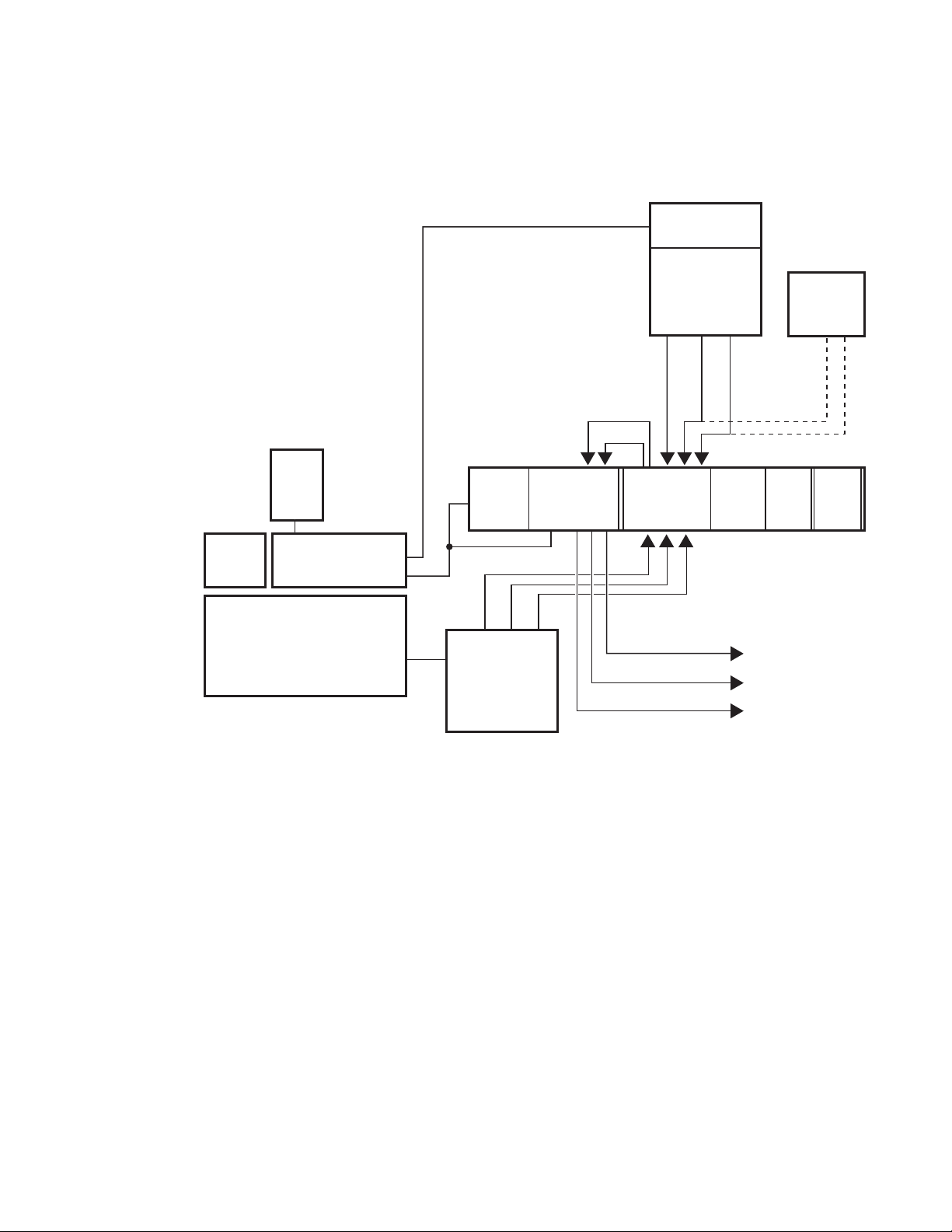
An example of an installed Kalypso Emergency Bypass system is shown in
Figure 1.
Figure 1. Emergency Bypass System
Router
Control
Menu
Panel
Backup
Power
Supply
(option)
Kalypso
Main
Panel
Local Aux
Panel
Emergency Bypass
RS-422
Breakout Cable
RS-422
(8900 TF Frame)
Bypass
Frame
Monitor
Module
Pvw
Pgm 1
Pgm 2
Kalypso
Video
Processor
Frame
Bypass
Relay
Module
Pgm
Pvw
Bkgd Video
Bypass
Keyer
Module
Pgm 1 Out
Pgm 2 Out
Pvw Out
Router
Matrix
Video/Key 2
Video/Key 1
External
Video & Key
Sources
Video/Key
from Router
or Direct
Power
Supply
Backup
Power
(option)
0721_07_59_r6
Emergency Bypass Frame
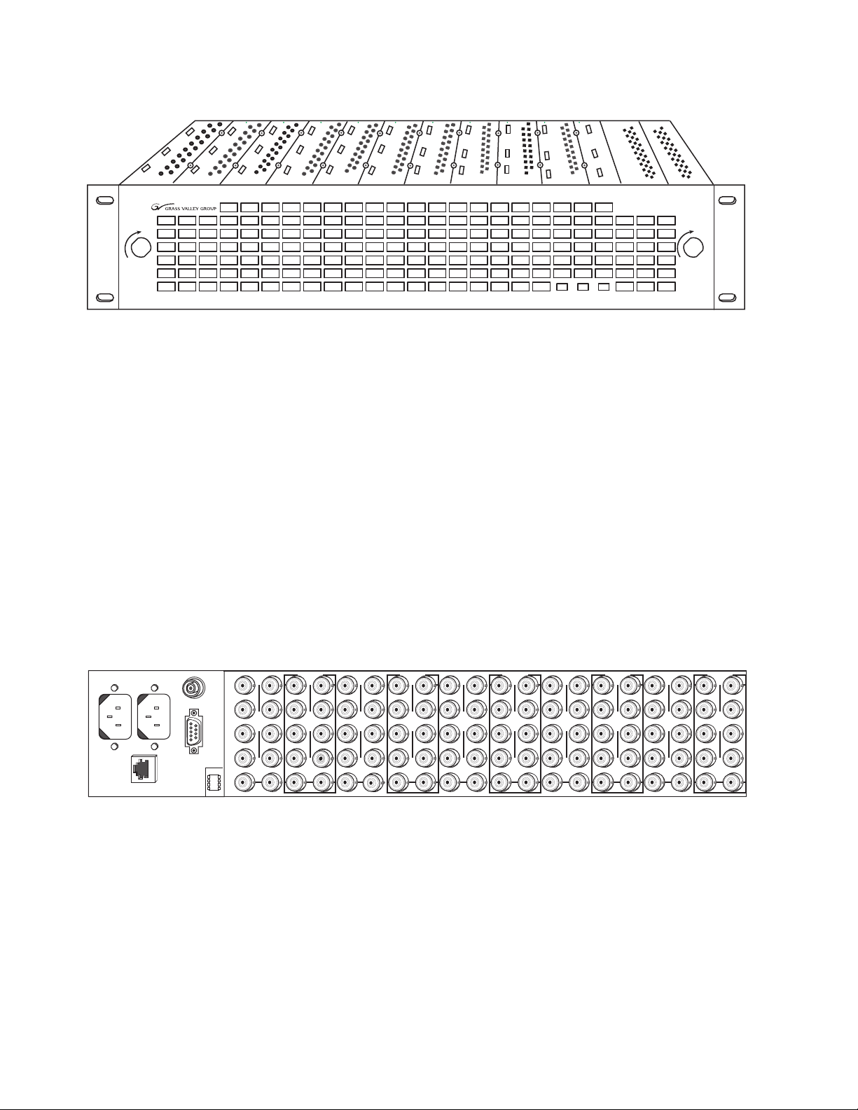
The 2 RU Emergency Bypass frame (Figure 2) fits a standard 19 in. (483
mm) equipment rack, and requires a 14 in. (356 mm) mounting depth.
Behind the front cover are ten slots for modules, plus one control slot and
two slots for power supplies.
Kalypso Emergency Bypass Option Instruction Manual 7
Page 8
Emergency Bypass Components
Figure 2. 8900TF Frame, Front View
LOCK LOCK
8900 Series
J1 J2
ETHERNET
J103
RS232
SMPTE
ALARM
J101
J102
FAULT PS1 PS2
CAUTION The Emergency Bypass frame front panel must remain in place during system
operation to provide proper cooling. If the panel is removed for an extended
period, modules can overheat and fail to operate correctly.
The forced-air system has a front cover that is equipped with three fans for
air circulation. The fan speed varies with the ambient frame temperature to
extend fan life and reduce noise when the frame is used in cooler configurations and environments. The fan speed control voltage is generated on
the Bypass Frame Monitor module and can be disabled so that the fan runs
at maximum speed only (see page 24).
The right rear of the frame (Figure 3) includes ten groups of ten connectors
(corresponding to the ten frame slots), which are used for input/output
functions for inserted modules. The standard Kalypso Emergency Bypass
option only uses two of these groups, typically slot 7 for the Relay Module
and slot 8 for the Keyer module.
Figure 3. 8900TF Frame, Rear View
10
J1 J2
O
J3 J4
U
T
J5 J6
J7 J8
J9 J10
IN
J2
J1 J2
J4
J3 J4
J6
J5 J6
J8
J7 J8
J9 J10
9
O
U
T
J1
IN
8
J1 J2
O
J3 J4
U
T
J5 J6
DA10
J7 J8
J9 J10
IN
J1
7
J2
J1 J2
O
J4
J3 J4
U
T
J6
J5 J6
J8
J7 J8
J9 J10
DA10
IN
6
J1 J2
O
J3 J4
U
T
J5 J6
J7 J8
J9 J10
IN
J1 J2
J2
O
J3 J4
J4
U
T
J5 J6
J6
J7 J8
J8
J9 J10
IN
5
4
J1 J2
O
J3 J4
U
T
J5 J6
J7 J8
J9 J10
IN
J1 J2
J2
J3 J4
J4
J5 J6
J6
J7 J8
J8
J9 J10
3
O
U
T
IN
2
J1 J2
O
J3 J4
U
T
J5 J6
J7 J8
J9 J10
IN
J1 J2
J3 J4
J5 J6
J7 J8
O
U
T
J9 J10
IN
0619_05_03_r0
1
0619_05_04_r1
The power/communication section at the left rear of the frame provides:
•RS-422 communications (the connector is labeled RS-232, but is RS-422
when the Bypass Frame Monitor module is installed),
• AC power plug connections, and
•SMPTE Alarm BNC (J101) for fault reporting (see below).
The Ethernet connector is not used with the Kalypso Emergency Bypass
option.
8Kalypso Emergency Bypass Option Instruction Manual
Page 9

Alarms
The J101 SMPTE Alarm connector retains the original 8900 system functionality when the Emergency Bypass version of the Frame Monitor
module is installed. Normal 8900 system faults (P/S failure, fan failure,
etc.) will trigger the alarm. Also the Bypass Keyer module triggers the
alarm upon some startup failures. The Bypass Relay module has no alarms.
See page 24 for more information.
Emergency Bypass Relay Module
The Bypass Relay module switches incoming video from normal to bypass
operation. The toggle switch must be in the center
remote activation of bypass operation. See page 27 for more information.
Emergency Bypass Keyer Module
The Bypass Keyer module keys up to two signals over incoming video, and
provides Program and Preview outputs. The keying can be set for shaped
or unshaped video (page 20). Also see page 25 for more information.
Panel Controls
Remote
position to allow
Emergency Bypass Frame Monitor Module
The Bypass Frame Monitor module provides system control, communications, and alarm reporting. See page 23 for more information.
Note
The Kalypso Emergency Bypass Frame Monitor module is not a standard
8900 Frame Monitor module. It is specifically designed for use with the
Kalypso Emergency Bypass system and RS-422 communications with the
Local Aux panel.
Frame Restrictions
•The Emergency Bypass frame hardware is designed to integrate closely
with the Kalypso system and is intended only for that purpose. Only
Emergency Bypass modules should be installed in the frame.
CAUTION Do not install any other types of 8900 series modules in the Emergency
Bypass frame.
•Browser based GUI control and monitoring normally associated with
the 8900 series is not available on the Emergency Bypass frame.
Panel Controls
The Kalypso Local Aux panel (or Local Aux subpanel on a 2-M/E system)
is used for Emergency Bypass operation (Figure 4).
Kalypso Emergency Bypass Option Instruction Manual 9
Page 10
Operation
Emergency
Bypass
Control
Figure 4. Local Aux Panel Emergency Bypass Controls
Current Background
Name Display
Source
Selection
Bypass
Enable
Bypass Active
Key
1
The
Bypass Enable
Assign
Key
2
Bypass
Deleg
button, when pressed with
enables and disables emergency bypass mode. The
Kalypso Source
Name Displays
Bypass Deleg
held down,
Bypass Enable
button illu-
minates when in bypass mode.
Note
The
If a BYPASS KEYER NOT ENABLED message appears you need to turn on the
option in the Eng Setup - Emg Bypass menu ( Enable touch button). Enabling
the Emergency Bypass option in this menu is different from enabling the
operating mode itself on the Local Aux panel.
Bypass Deleg
button, besides being used to enable bypass mode above,
is used to delegate the Source Selection buttons to control the Background,
Keyer 1, or Keyer 2 buses for source selection (see below).
Pressing the
program output. When
the
Key 1
or
or
Key 1
button delegates the Source Selection buttons to that keyer
Key 2
button mixes that key on or off on the bypass
Key 2
Bypass Deleg
is held down, pressing and releasing
bus.
0721_07_61_r0
The Source Selection buttons are used (when the
Bypas Deleg
button is on) to
select the Background, Key 1, or Key2 sources, depending on the current
bus delegation (see above). The names of the currently available sources
are displayed on the middle source name display. The name of the currently selected background source is also displayed above the
Bypass Deleg
button.
Operation
The Emergency Bypass system operates with Kalypso Release 6.0 and
higher software.
10 Kalypso Emergency Bypass Option Instruction Manual
Page 11

Operation
1.
Note
Emergency Bypass operation becomes available after the Kalypso system,
Emergency Bypass frame, and the external Router have been properly
installed (see page 12) and configured (see page 19).
Emergency Bypass operation consists of selecting the desired background
and key sources, enabling and disabling bypass mode, and mixing the key
sources on and off air.
Note
Release 6.X software supports background and key source selection only
when Bypass Operating Mode is enabled on the Local Aux panel. Release 7.0
and later software supports source selection when the Local Aux panel is not
actually in Bypass Operating Mode, permitting pre-selection of sources
before activating the mode.
To Select Background Bypass Sources:
Press the button of the desired source on the top source selection bus of the
Local Aux panel. The
Unshift
and
modifier buttons for that bus can be
Shift
used to select additional sources if they have been mapped that way.
To Select Key Sources:
Note
Only key sources from the router can be selected. Direct key sources are fixed
and cannot be changed.
Hold down the
Key 2
button, but continue to hold down
Bypass Deleg
button, then press and release the
Bypass Deleg
. Press the button of
the source you wish to use with the key you selected. The
Shift modifier buttons for that bus can be used to select additional
Key 1
Unshift
or
and
sources. If that key is being output, there will be a cut to the new key
source.
2. Release the Bypass Deleg button. This restores the bus to background
selection.
To Enable Bypass Operating Mode:
1. Press and hold down the Bypass Deleg button on the Local Aux panel,
2. Press the Bypass Enable button, then release both buttons.
The currently selected bypass background source will be taken on-air. Any
keys that are turned on will also be included in the bypass output.
To r eturn to normal operation, press and hold down
Bypass Enable and release both buttons to toggle bypass mode off.
Bypass Deleg, then press
To Mix a Key On and Off:
1. Press the Key 1 or Key 2 button (do not hold down the Bypass Deleg
button). That key will mix to the other state (On if Off, or Off if On).
Kalypso Emergency Bypass Option Instruction Manual 11
Page 12

Installation
Installation
SMS 7000 Router Requirements
2. The transition rate for each key is determined during configuration. A
transition rate of zero causes a cut.
Note Each Grass Valley router control system can control a wide variety of
matrices. The type of matrix controlled does not affect operation of the
Kalypso Emergency Bypass option.
•A CIF (communication interface) Module Option must be installed
with its Serial Mezzanine in position 1 of the option module to allow
the SMS 7000 to communicate using native protocol over a serial line.
Encore Router Requirements
•An SIO ISA Mezzanine must be installed for serial communications.
Install Emergency Bypass Frame
The Emergency Bypass frame ships either with the modules pre-installed,
or with the modules packaged separately.
1. Install the Emergency Bypass frame in any suitable rack.
2. If the modules were packaged separately, remove the front cover and
insert the modules into the frame. For cooling efficiency, the modules
should be placed in the following slots:
a. Insert the Bypass Relay module in slot 7.
b. Insert the Bypass Keyer module in slot 8.
c. Insert the Bypass Frame Monitor module into the smaller control
slot 11.
3. Connect the Emergency Bypass frame power cords, using different line
sources if redundant power supplies are being used.
12 Kalypso Emergency Bypass Option Instruction Manual
Page 13

Panel Cabling and Redundant Power
4-M/E Local Aux Panel
The Local Aux panel is typically powered through a cable connected to the
Main panel. If the Main panel has two power supplies, redundant power
protection for the Local Aux panel already exists. For additional redundancy, an external power supply brick can be connected to the Redundant
DC Power In connector on the Local Aux panel. If desired, two separate
power supply bricks can be connected to the Main and Redundant DC
Power In connectors on the Local Aux panel.
2-M/E Panel
Local Aux control is integrated into the 2-M/E Main panel, but it has a separate processor. It is powered by a direct connection inside the panel. If the
2-M/E Main panel has two power supplies, redundant power protection
for the Local Aux panel already exists. You can optionally add an external
power supply that connects to the Aux Panel Redundant DC Power In connector on the Main panel.
Installation
2-M/E System Cable Replacement
On older 2-M/E Kalypso systems a ribbon cable must be replaced with a
new cable supplied with the Emergency Bypass option. This cable routes
power from the Local Aux panel Backup Power option to the Remote Aux
subpanel. Newer 2-M/E systems are shipped with the correct cable already
installed. This ribbon cable is not used on 4-M/E systems.
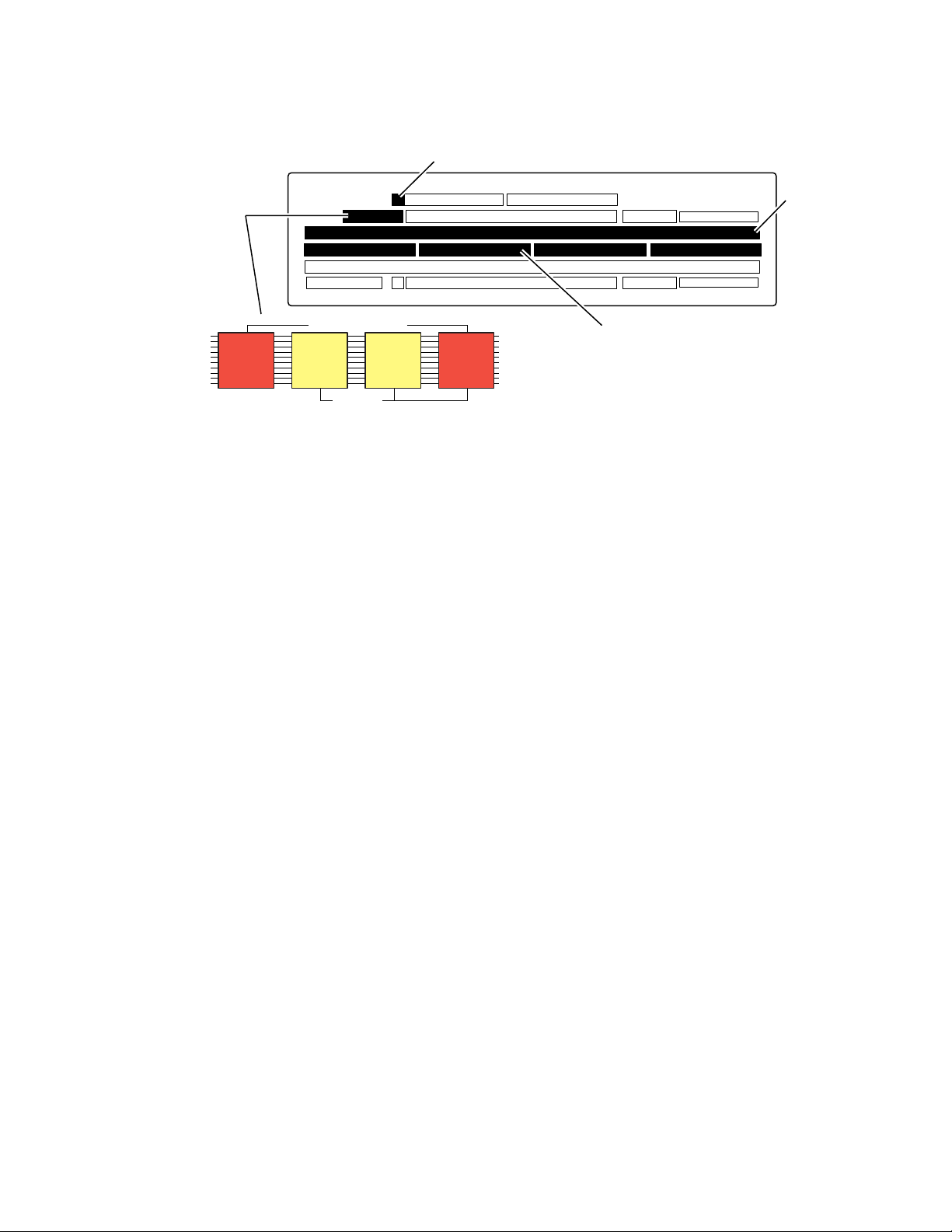
Ribbon Cable Identification
1. Open the 2-M/E Main panel lid.
• If a ribbon cable connects three boards in the upper lid near the hinge
(Figure 5), it must be replaced to enable optional backup power with
the Emergency Bypass option. Go to Local Aux Processor Interface Board
Version on page 14.
• If the ribbon cable connects two boards on the lid to the Local Aux Processor Interface board, a new cable is already installed and does not
need to be replaced. Close the lid and go to Control Cabling on page 17.
Kalypso Emergency Bypass Option Instruction Manual 13
Page 14

Installation
Figure 5. 2-M/E System Old Ribbon Cable
Local Aux Processor
Interface Board
Old Cable
To Be Replaced
S
A
T
E
L
L
I
T
E
P
O
T
R
R
T
A
S
N
S
M
I
T
G
E
N
E
R
8
A
L
8
P
8
U
R
8
P
O
8
S
E
8
8
8
L
E
D
S
G
P
7
R
G
E
P
C
5
E
I
G
V
P
E
5
G
P
0
T
R
A
N
S
M
I
T
G
P
8
G
P
6
G
P
4
G
P
1
S
A
T
E
L
L
I
T
R
E
E
P
C
O
E
R
I
V
T
E
S
4
5
6
3
7
2
8
1
9
0
R
T
P
/
C
O
F
N
A
T
U
R
L
T
O
L
A
P
C
A
T
N
I
E
V
L
I
T
L
Y
A
C
N
1
1
9
I
N
I
T
R
P
U
O
N
W
E
R
S
X
U
M
P
T
C
P
L
2
I
9
E
S
R
C
V
R
M
1
5
E
1
P
N
R
L
U
O
I
N
C
K
R
E
1
S
5
S
R
2
O
C
E
R
O
S
L
E
N
T
R
1
5
3
3
.
3
V
5
V
1
2
V
S
C
S
I
H
A
R
D
D
I
S
K
0721_07_68_r0
Local Aux Processor Interface Board Version
2. Determine which type of Local Aux Processor board (Figure 5) is
installed in your system. Cable installation is different depending on
board type. The part number of the board is visible behind the fan
assembly.
• If the part number is lower than 671-4945-02, the board will not
work with the Emergency Bypass option. Do not remove or replace
the cable. Contact Grass Valley Customer Service for an upgrade.
• If 671-4945-02, go to Older Board Cable Replacement (671-4945-02) on
page 14.
• If 671-4945-03, go to Newer Board Cable Replacement (671-4945-03) on
page 15.
Older Board Cable Replacement (671-4945-02)
1. Power off the 2-M/E Main panel.
2. Remove the old ribbon cable from the lid (Figure 5).
3. Attach the two closely spaced connectors on the new cable to the same
two boards in the lid (Figure 6). The red marked edge of the ribbon
cable must face down toward the hinge of the lid, to match the pin 1 and
2 side of the connector. These connectors are keyed for this orientation.
14 Kalypso Emergency Bypass Option Instruction Manual
Page 15

Figure 6. Older Board (671-4945-02) Cable Installation
New Replacement
S
A
T
E
L
L
I
T
E
P
O
T
R
R
T
A
S
N
S
M
I
T
G
E
N
E
R
8
A
L
8
P
8
U
R
8
P
O
8
S
E
8
8
8
L
E
D
S
G
P
7
R
G
E
P
C
5
E
I
G
V
P
E
5
G
P
0
T
R
A
N
S
M
I
T
G
P
8
G
P
6
G
P
4
G
P
1
S
A
T
E
L
L
I
T
R
E
E
P
C
O
E
R
I
V
T
E
Final
S
Cable
Routing
Local Aux Processor
Interface Board
(Older Model )
Cable
4
5
6
3
7
2
8
1
9
0
Installation
R
T
P
/
C
O
F
N
A
T
U
R
L
O
T
L
A
P
C
A
T
N
I
E
V
L
I
T
L
Y
A
C
N
1
1
9
I
N
I
T
R
P
U
O
N
W
E
R
S
X
U
M
P
T
C
P
L
2
I
9
E
S
R
C
V
R
M
1
5
E
1
P
N
R
L
U
O
I
N
C
K
R
E
1
S
5
S
R
2
O
C
E
R
O
S
E
L
N
T
R
1
5
3
3
.
3
V
5
V
1
2
V
S
C
S
I
H
A
R
D
D
I
S
K
0721_07_69_r2
4. An interconnecting dual 10-pin header assembly with short and long
pins is provided with the kit. If not already installed, insert the side of
the assembly with the short pins into the remaining open ribbon cable
connector, making sure all connector sockets are filled.
CAUTION Use care when connecting the ribbon cable to the Local Aux Processor Inter-
face board. The connector is not keyed, and equipment damage can occur if
the connector is installed misaligned with the pins.
5. The remaining connector with the header assembly pins protruding
attaches to the J3 connector on the lower left corner of the 671-4945-02
Local Aux Processor Interface board. Orient the cable with the ribbon
emerging from the right side of the connector. The red marked edge of
the ribbon cable must face down toward the bottom of the tub,
matching the pin 1 and 2 side of the connector on the board.
6. Route the cable alongside the power supply (Figure 6), using the
supplied adhesive cable restraints.
7. Close the lid and power up the Main panel.
Newer Board Cable Replacement (671-4945-03)
1. Power off the 2-M/E Main panel.
2. Remove the old ribbon cable from the lid (Figure 5).
Kalypso Emergency Bypass Option Instruction Manual 15
Page 16

Installation
3. Attach the two closely spaced connectors on the new cable to the same
two boards in the lid (Figure 7). The red marked edge of the ribbon
cable must face down toward the hinge of the lid, to match the pin 1 and
2 side of the connector. These connectors are keyed for this orientation.
Figure 7. Newer Board (671-4945-03) Cable Installation
New Replacement
Cable
S
A
T
E
L
L
I
T
E
P
O
T
R
R
T
A
S
N
S
M
I
T
G
E
N
E
R
8
A
L
8
P
8
U
R
8
P
O
8
S
E
8
8
8
L
E
D
S
G
P
7
R
G
E
P
C
5
E
I
G
V
P
E
5
G
P
0
T
R
A
N
S
M
I
T
G
P
8
G
P
6
G
P
4
G
P
1
S
A
T
E
L
L
I
T
R
E
E
P
C
O
E
R
I
V
T
E
Final
Cable
Routing
Local Aux Processor
S
4
5
6
3
7
2
8
1
9
0
R
T
P
/
C
O
F
N
A
T
U
R
L
T
O
L
A
P
C
A
T
N
I
E
V
L
I
T
L
Y
A
C
N
1
1
9
I
N
I
T
R
P
U
O
N
W
E
R
S
X
U
M
P
T
C
P
L
2
I
9
E
S
R
C
V
R
M
1
5
E
1
P
N
R
L
U
O
I
N
C
K
R
E
1
S
5
S
R
2
O
C
E
R
O
S
L
E
N
T
R
1
5
3
3
.
3
V
5
V
1
2
V
S
C
S
I
H
A
R
D
D
I
S
K
Interface Board
(Newer Model)
4. An interconnecting assembly with short and long pins is provided with
the kit. If not already installed, insert the side of the assembly with the
short pins into the remaining open ribbon cable connector, making sure
all connector sockets are filled.
CAUTION Use care when connecting the ribbon cable to the Local Aux Processor Inter-
face board.The connector is not keyed, and equipment damage can occur if
the connector is installed misaligned with the pins.
5. The remaining connector with the long pins protruding attaches to the
J2 connector on the lower left corner of the 671-4945-03 Local Aux
Processor Interface board. Orient the cable with the ribbon emerging
from the left side of the connector. The red marked edge of the ribbon
cable must face up toward the opening of the tub, matching the pin 1
and 2 side of the connector on the board.
0721_07_70_r2
6. Route the cable alongside the power supply (Figure 7), using the
supplied adhesive cable restraints.
7. Close the lid and power up the Main panel.
16 Kalypso Emergency Bypass Option Instruction Manual
Page 17

Control Cabling
Note Some early production models of the Kalypso Local Aux panel and 2-M/E
Refer to Figure 8.
•Connect an RS422 cable from the Emergency Bypass Mixer port on the
•Connect the multi-pin breakout connector to the serial port (J102) on
Installation
Main panel reversed the legends for the Emergency Bypass ports. Later
models had corrective labels applied at the factory. Current models are silkscreened correctly. If after installation Emergency Bypass does not work on
an older system, try reversing these cables. Labels are provided (EBS MIXER,
EBS ROUTER) that can be cut out and affixed over incorrect legends. Ensure
proper system operation before relabeling the connectors.
Local Aux panel or 2-M/E Main panel to the provided breakout serial
cable.
the rear of the Emergency Bypass frame, then connect the BNC breakout connector to the J9 or J10 port of the slot where the Bypass Relay is
placed (typically slot 7). Do not terminate the open J9 or J10 port. It can
be used to control additional Bypass Relay modules. The BNC on the
breakout cable is used for contact closure only, and does not carry any
signal.
•Connect an RS422 cable from the Emergency Bypass Router port on the
Local Aux panel or 2-M/E Main panel to the serial port for the CIF
Module Option (ASYNC 1B) on the SMS 7000 MCPU/Controller
Frame.
Note The ground connection on the SMS 7000 serial connector is different. Please
refer to the SMS 7000 Installation Manual for cable details.
Kalypso Emergency Bypass Option Instruction Manual 17
Page 18

Installation
Figure 8. Emergency Bypass Cabling
Bypass Keyer Module
8900TF Frame Cell 8
Use DAs here if monitoring
or multiple Relay Modules
are required.
SMS 7000
Router
RS-422
Kalypso
Local
Aux Panel
Kalypso
Video
Processor
Frame
Key Cut 1
Key Cut 2
Key Fill 1
Key Fill 2
Background
Analog 525/625
Reference
Emg Bypass
Router
Emg Bypass
Mixer
PVW
Pgm 1
Terminate
or Loop
RS-422
J3
J4
J5
J6
J7
J9
Looping
Reference
J10
Input
Bypass Monitor Module
8900TF Frame Cell 11
J102
Pvw J2
Pgm J1
Breakout Cable
Bypass Relay Module
8900TF Frame Cell 7
J3
J1
J4
J5
J7
J9
J10
Do
Not
Terminate
J2
J6
J8
Pvw Out
Pgm 1 Out
Pgm 2 Out
Pgm 2
Video Cabling
0721_07_62_r3
Note Label templates are provided (BYPASS KEYER and BYPASS RELAY) that can
be placed over the BNC connectors on the rear of the Emergency Bypass
frame. These templates identify the signals for each module.
Refer to Figure 8.
•Connect the Router destinations for Key Cut, Key Fill, and Background
signals to the Bypass Keyer Module, using the J connector numbers
shown in the figure. Alternatively, the Key Cut and Fill signals can
come from an external device, but then these signals cannot be
switched from the Kalypso Local Aux panel.
•Connect the Program 1 Output from the Kalypso Video Processor
frame to the Relay Module, as shown. You can also connect another
Program output and a Preview output if you wish.
•Connect the J1 output (Program) from the Keyer Module to the J4 input
of the Relay Module, and the J2 output (Preview) to the J3 input.
18 Kalypso Emergency Bypass Option Instruction Manual
Page 19

Reference
Configuration
Configuration
•Connect the J6 Program 1 (and J8 Program 2 if used) outputs of the
Relay Module to your downstream targets (monitor, transmitter). The
bypass program output signals are identical.
•Connect the J2 Pvw Out of the Relay Module to a Kalypso system
preview monitor (typically switched preview or PGM PST PVW A).
When Emergency Bypass is not active, this output shows the normal
preview signal. When Emergency Bypass is active, the preview for the
Emergency Bypass keyer is shown, consisting of the current background with both keys on.
Connect a black burst video reference to J9 or J10 on the Keyer module,
either terminated or looped through (Figure 8).
SMS 7000 Router
If the SMS 7000 router is not already configured, you will need to define the
node controller, physical matrix, virtual matrix, levels, sources, and destinations (see the SMS 7000 Configuration Manual).
Confirm that a CIF Module Option is installed, with its Serial Mezzanine in
module position 1. To configure this option for communication with the
Kalypso Local Aux panel:
1. Open your existing Router configuration using the SMS 7000 GUI.
2. Go to Setup/Cfgd Np Internet, and edit NPI1, identifying the levels you wish
the Kalypso system to be able to control.
3. Go to the Serial Amezi menu, and select the Native (& m2100) protocol,
and set it to RS422.
4. Set the following serial settings:
• 422 driver, 9600 baud, 8 data bits, no parity, 1 stop bit.
5. In the Co-processors menu, create a new co-processor for this serial
Amezi.
6. If necessary, go to Configuration/Destination and add any new destinations
that will be used for the Emergency Bypass system. You will need to
specify the proper levels if a destination is a video /key pair and note
the names and connector numbers.
Kalypso Emergency Bypass Option Instruction Manual 19
Page 20

Configuration
Encore Router
7. Send this configuration to the SMS 7000 system. The router is now
configured for serial communication.
Encore router configuration procedures are similar to those used for the
SMS 7000 system. An Encore router communicates to the Kalypso system
via an RCL client. RCL is a superset of the SMS 7000 native protocol. The
Encore serial COM 2 port is configured for RCL at the factory.
Refer to the Encore system documentation for detailed instructions. Specifically, see the Encore Installation and Service Manual for information about
installing the SIO mezzanine, and see the Encore User Manual for configuration instructions.
The Kalypso system must have access to the Encore router serial digital
video and key levels feeding the Emergency Bypass system.
Kalypso System
Relay Module Switch Setting
The Emergency Bypass Relay Module switch must be set to the center
Remote position before the Kalypso system will be able to control it.
Switch position up forces bypass operation, and switch position down
forces normal operation.
Specifying Shaped or Unshaped Sources
The Keyer module can be set to accept shaped or unshaped video for
keying. The same selection is applied to all sources. Settings are retained
when power to the frame is cycled.
1. Set the dial switch on the Keyer Module (slot 8) to the desired mode:
2. Press the toggle switch to enact the change.
• Select 1 for shaped video.
• Select 2 for unshaped video.
Mapping Router Sources
You need to know the exact names of the router sources and destinations
that will be used by the Emergency Bypass system. Router names are case
sensitive, with a maximum of eight characters.
20 Kalypso Emergency Bypass Option Instruction Manual
Page 21

Configuration
The router sources you use with the Emergency Bypass system must be the
same sources used by the Kalypso system. Any sources connected to the
Kalypso system that are not connected to the router will not be available
when emergency bypass is activated.
Emergency bypass configuration menus are available with Kalypso
Release 6.0 and higher software.
1. Press the Eng Setup button on the Menu panel, touch the System category
selection button, then touch the
Bypass menu (Figure 9).
Figure 9. Emerg Bypass Menu
Emerg Bypass button to go the Emerg
2. In the Source Cross Reference pane, touch the data pad for a switcher
input (the Source ID and source name is displayed), and enter the exact
name of the router source you wish to use for this switcher source
during Emergency Override operations. Typically this will be the same
signal, coming from the router instead of feeding the Kalypso system.
Repeat for all the sources you intend to use. The
be used to scroll the list.
3. In the Router Buses pane, touch the BKGD data pad and enter the exact
name of the router destination to be used for the Emergency Bypass
background signal. This destination is the one connected to the Keyer
Module in the Emergency Bypass frame.
Sources soft knob can
Kalypso Emergency Bypass Option Instruction Manual 21
Page 22

Configuration
4. Setup the keyer signals that are connected to the Keyer Module in the
Emergency Bypass frame.
• If you are using a key from the router, touch the
keyer and enter the exact name of router destination to be used for
that keyer.
• If you are using a direct input for a key, touch the
5. Enter the mix rate for each key, by touching the Key Mix data pad and
entering a value, or using the soft knob. The key mix rate is displayed
in seconds : frames format. The knob can be rotated to increment and
decrement the mix rate in frames. The mix rate can also be entered
from the keypad in seconds : frames format or just as frames. A value
of 0 frames causes a cut transition.
6. Touch the Enable button to enable the option. This initiates
communication between the Local Aux panel, Emergency Bypass
frame, and external Router, and activates the bypass buttons on the
Local Aux panel.
If the Emergency Bypass option is not present, but it is enabled in this
menu, pressing the bypass buttons on the Local Aux panel will display a
warning message indicating the system is not responding. If the Emergency Bypass option is not present, it should be shut down in this menu to
deactivate the Local Aux panel bypass buttons and prevent display of the
warning message.
Router button for the
Direct button.
Test Emergency Bypass
You can now test Emergency Bypass operation (this should be done when
not actually on-air, of course). See page 10 for operating instructions.
22 Kalypso Emergency Bypass Option Instruction Manual
Page 23

Maintenance
Bypass Frame Monitor Module
Indicator LEDs
Maintenance
The Bypass Frame Monitor Module provides indicator LEDs on the front
of the module (visible when fan front cover is removed) that report alarm
conditions and module power status. The front edge of the Bypass Frame
Monitor Module is shown in Figure 10.
Figure 10. Bypass Frame Monitor Module Front View
Temperature (red)
PS2 (red)
PS1 (red)
Fan (red)
Power (green)
Module Health (red)
S1
Fault detected (red)
Configuration DIP switch S1
1
2
43
65
7
8
The possible LED status and conditions indicated are shown in Table 1.
Table 1. Indicator LEDs and Conditions Indicated
LED LED State Condition
Power
(green)
PS2
(red)
PS1
(red)
Off Power is off or onboard regulator has failed
On continuously Module is powered
Off Normal operation or alarm disabled
On continuously Power supply 2 is present and reporting an alarm condition
Off Normal operation or alarm disabled
On continuously Power supply 1 is present and reporting an alarm condition
Module Health Inhibited (yellow)
LED Color Key
Red = Fault
Green = OK
Yellow = Mode Active
0636 -16
Kalypso Emergency Bypass Option Instruction Manual 23
Page 24

Maintenance
Table 1. Indicator LEDs and Conditions Indicated - (continued)
LED LED State Condition
FAN
(red)
MOD
(red)
INHIB
(yellow)
FAULT
(red)
Off Normal operation or alarm disabled
On continuously One or more fans in the front cover assembly is not rotating
Off Normal operation or alarm disabled
On continuously Module health bus is not disabled and one or more modules is reporting an internal fault
Flashing One or more modules is reporting a data error
Off Normal operation or alarm disabled
On continuously A non-compliant module in the frame has disabled the module health bus
Off Normal operation
On continuously One or more of the onboard fault LEDs is illuminated or flashing
Enabling Alarms and Fan Speed Control Option
The Bypass Frame Monitor Module has an eight position DIP switch (S1)
that enables or disables the alarm functions and the variable fan speed
function, same as a standard 8900 Frame Monitor module. In addition, an
RS-422 setting used only by the Bypass module is available, but must be set
to the normal position.
Refer to Figure 10 for the location of S1 and Table 2 for the possible settings.
Table 2. Configuration DIP Switch Settings
Segment Left Position (open) Right Position (closed)
1 PS1 Fault Reporting Enabled PS1 Fault Reporting Disabled
2 PS2 Fault Reporting Enabled PS2 Fault Reporting Disabled
3 Overtemp Fault Reporting Enabled Overtemp Fault Reporting Disabled
4 Fan Fault Reporting Enabled Fan Fault Reporting Disabled
5 Module Fault Reporting Enabled Module Fault Reporting Disabled
6 Fan Speed Controlled by Temperature Fan Speed Fixed at Maximum
7 Not Used
8 RS-422 Normal RS-422 Reversed
a
Emergency Bypass does not operate with a reversed setting.
a
24 Kalypso Emergency Bypass Option Instruction Manual
Page 25

Bypass Keyer Module
_
_
_
Indicator LEDs
The Bypass Keyer module has LED indicators above the rotary switch
(Figure 11).
Figure 11. Bypass Keyer Module
FAULT
COMM
CONF
PWR
625
LOCK
REF PRESENT
FUNCTION – rotary switch
(1-Shaped, 2-Unshaped)
Maintenance
JP4
SW1 – actuator toggle switch JP3 – jumper required on right
JP2
JP3
JP1
The possible LED status and conditions indicated are shown in Table 1.
Table 1. Indicator LEDs and Conditions Indicated
LED LED State Condition
FAULT
(red)
COMM
(yellow)
CONF
(yellow)
PWR
(green)
625
(green)
LOCK
(red)
REF
PRESENT
(red)
Off Normal operation
On continuously Module FPGA is not configured or fails to configure
Off -
Flickers Communications activity under way
Off -
On continuously Module is being configured
Off Power is off or onboard regulator has failed
On continuously Module is powered
Off -
On continuously 625 line reference is detected
Off -
On continuously Module has acquired lock on reference input
Off Reference signal not detected
On continuously
Reference signal detected
r1
01
01
8121
Kalypso Emergency Bypass Option Instruction Manual 25
Page 26

Maintenance
Rotary and Actuator Switches
The rotary switch sets a module operating mode, which is enacted by
moving the toggle switch either up or down. Rotary position 1 selects
shaped video for keying, position 2 selects unshaped video. The remaining
settings are for factory test and should not be used in the field.
Jumper Setting
The JP3 jumper needs to be bridged on the right (LOCAL) position
(Figure 11) for normal operation. All other jumpers are used for factory test
and should remain empty.
26 Kalypso Emergency Bypass Option Instruction Manual
Page 27

Bypass Relay Module
Indicator LEDs
The Emergency Bypass Relay module (Figure 12) has a single Power LED,
and two operating mode LEDs above and below the mode switch. The top
red LED indicates the module is in bypass operation. The lower green LED
indicates normal (non-bypass) operation.
Figure 12. Bypass Relay Module
PWR
Maintenance
BYPASS
NORMAL
SW1 – three position switch
(center position REMOTE)
Relay Module Switch
The three position switch (SW 1) can be used to change module operating
modes. The up position forces bypass operation, and the bottom position
forces normal (non-bypass) operation. The center
remote mode switching from the Local Aux panel.
Breakout Cable
The breakout Y cable (Figure 13) used between the Local Aux panel and
Emergency Bypass frame includes a BNC connector, which is used for
contact closure.
Figure 13. Breakout Cable and Pin Connections
DB-9
Female
J1
P1
DB-9
Male
P2
BNC
Remote position permits
From To Note
J1-1 P1-5 Use cable drain wire
J1-2 P1-2
J1-7 P1-7
J1-4 P2-Center
J1-6 P2-Shield
J1-3 P1-3
J1-8 P1-8
8121_01_03_r1
Twisted pair
BNC connector
Twisted pair
8121_01_02
Kalypso Emergency Bypass Option Instruction Manual 27
Page 28

Field Replaceable Units
Field Replaceable Units
Figure 14. FRU List and Replacement Notes and References
Name Part Number Replacement Notes and References
Emergency Override Option
Bypass Frame Monitor module 671-4802-10
Bypass Relay module 671-5198-00
Bypass Keyer module 671-5175-00
Wire Harness, Bypass Control Y Cable 179-3027-00
Machine Control Cable (RS-422) 054602-16
Ribbon Cable Assembly, (2-ME upgrade) 174-8067-01 For older 2-M/E systems only.
Frame 8900TX/TF/TFN 630-0063-00
Front Panel with Fan 644-0944-01
Power Supply Module (for Frame) 119-6055-51
28 Kalypso Emergency Bypass Option Instruction Manual
Page 29

Index
Numerics
2-M/E System
Local Aux Processor I/F board versions
2-M/E System cable replacement 13
A
alarms 9
enabling 24
B
Background bypass source
selecting
breakout cable 27
pinouts 27
button
Bypass Deleg
Bypass enable 10
Key 1, 2 10
Bypass Deleg button 10
Bypass Enable button 10
Bypass Frame Monitor module 9
LED status 23
Bypass Keyer module 9
jumper setting 26
LED status 25
switch 26
bypass operating mode
enable
Bypass Relay module 9
LED location 27
switch 27
switch setting 20
11
10
11
14
new board
old board 14
cabling
control
reference 19
video 18
cell
module placement
components 6
configuration
Encore router
Kalypso System 20
SMS 7000 router 19
control cabling 17
controls 9
cooling 8
15
17
12
20
D
disables 24
documentation online 2
E
Emergency Bypass frame
installing
Emergency Bypass option
general description
enable bypass operating mode 11
enables 24
Encore router
configuration
interface requirements 12
Ethernet connector 8
external power supply brick 13
12
5
20
C
cable
breakout
breakout pinouts 27
cable replacement
Kalypso Emergency Bypass Option Instruction Manual 29
27
F
fan 8
fan speed control 24
FAQ database 2
Page 30

Index
features 6
field replaceable units (FRU) 28
frame 7
front cover 8
module cells 12
restrictions 9
Frame Monitor module
see Bypass Frame Monitor module
frequently asked questions
front cover
frame
8
2
G
Grass Valley web site 2
I
installation
2-M/E System cable replacement
Emergency Bypass frame 12
Encore router requirements 12
SMS 7000 router requirements 12
J
jumper
Bypass Keyer Module setting
26
13
Bypass Frame Monitor module
Bypass Keyer Monitor module 25
Local Aux Processor I/F board versions
2-M/E System
14
23
M
mapping router sources 20
mixing a key on and off 11
modules
cell placement
packaged separately 12
pre-installed 12
Monitor module
see Bypass Frame Monitor module
12
O
online documentation 2
operation 11
options 6
P
pinouts
breakout cable
power supply brick 13
27
K
R
Kalypso System configuration 20
key
mixing on and off
Key 1,2 button 10
key source
selecting
Keyer module
see Bypass Keyer module
11
11
L
LED location
Bypass Frame Monitor module
Bypass Keyer module 25
Bypass Relay Module 27
LED status
30 Kalypso Emergency Bypass Option Instruction Manual
23
redundant power 13
reference cabling 19
Relay module
see Bypass Relay module
RS-422 communications
8
S
selecting background bypass source 11
selecting key source 11
shaped video
selecting
SMS 7000 router
configuration
interface requirements 12
software download from web 2
20
19
Page 31

Source Selection bus
use with Emergency Bypass option
sources
mapping
switch
Bypass Keyer module
Bypass Relay module 27
20
26
U
unshaped video
selecting
20
V
variable fan speed 24
video cabling 18
Index
10
W
web site documentation 2
web site FAQ database 2
web site Grass Valley 2
web site software download 2
Kalypso Emergency Bypass Option Instruction Manual 31
Page 32

Index
32 Kalypso Emergency Bypass Option Instruction Manual
 Loading...