

Page 1

Kalypso
VIDEO PRODUCTION CENTER
User Manual
SOFTWARE VERSION 15.0
071061815
DECEMBER 2007
Page 2

Affiliate with the N.V. KEMA in The Netherlands
CERTIFICATE
Certificate Number: 510040.001
The Quality System of:
Grass Valley, Inc.
400 Providence Mine Road
Nevada City, CA 95945
United States
15655 SW Greystone Ct.
Beaverton, OR 97006
United States
10 Presidential Way
3
rd
Floor, Suite 300
Woburn, MA 01801
United States
Nederland B.V.
4800 RP BREDA
The Netherlands
Weiterstadt, Germany
Brunnenweg 9
D-64331 Weiterstadt
Germany
Rennes, France
Rue du Clos Courtel
Cesson-Sevigne, Cedex
France
Technopole Brest Iroise
CS 73808
29238 Brest Cedex 3
France
17 rue du Petit Albi-BP 8244
95801 Cergy Pontoise
Cergy, France
2300 South Decker Lake Blvd.
Salt Lake City, UT 84119
United States
7140 Baymeadows Way
Suite 101
Jacksonville, FL 32256
United States
Including its implementation, meets the requirements of the standard:
ISO 9001:2000
Scope:
The design, manufacture and support of video hardware and software products and
related systems.
This Certificate is valid until: June 14, 2009
This Certificate is valid as of: August 30, 2006
Certified for the first time: June 14, 2000
H. Pierre Sallé
President
KEMA-Registered Quality
The method of operation for quality certification is defined in the KEMA General Terms
And Conditions For Quality And Environmental Management Systems Certifications.
Integral publication of this certificate is allowed.
KEMA-Registered Quality, Inc.
4377 County Line Road
Chalfont, PA 18914
Ph: (215)997-4519
Fax: (215)997-3809
CRT 001 073004
ccredited By:
ANAB
A
Page 3
Kalypso
VIDEO PRODUCTION CENTER
User Manual
SOFTWARE VERSION 15.0
071061815
DECEMBER 2007
Page 4

Contacting Grass Valley
International
Support Centers
Local Support
Centers
(available
during normal
business hours)
France
24 x 7
Australia and New Zealand: +61 1300 721 495 Central/South America: +55 11 5509 3443
Middle East: +971 4 299 64 40 Near East and Africa: +800 8080 2020 or +33 1 48 25 20 20
Europe
+800 8080 2020 or +33 1 48 25 20 20
+800 8080 2020 or +33 1 48 25 20 20
Hong Kong, Taiwan, Korea, Macau: +852 2531 3058 Indian Subcontinent: +91 22 24933476
Asia
Southeast Asia/Malaysia: +603 7805 3884 Southeast Asia/Singapore: +65 6379 1313
China: +861 0660 159 450 Japan: +81 3 5484 6868
Belarus, Russia, Tadzikistan, Ukraine, Uzbekistan: +7 095 2580924 225 Switzerland: +41 1 487 80 02
S. Europe/Italy-Roma: +39 06 87 20 35 28 -Milan: +39 02 48 41 46 58 S. Europe/Spain: +34 91 512 03 50
Benelux/Belgium: +32 (0) 2 334 90 30 Benelux/Netherlands: +31 (0) 35 62 38 42 1 N. Europe: +45 45 96 88 70
Germany, Austria, Eastern Europe: +49 6150 104 444 UK, Ireland, Israel: +44 118 923 0499
Copyright © Grass Valley. All rights reserved.
This product may be covered by one or more U.S. and foreign patents.
United States/Canada
24 x 7
+1 800 547 8949 or +1 530 478 4148
Grass Valley Web Site
The www.thomsongrassvalley.com web site offers the following:
Online User Documentation — Current versions of product catalogs, brochures,
data sheets, ordering guides, planning guides, manuals, and release notes
in .pdf format can be downloaded.
FAQ Database — Solutions to problems and troubleshooting efforts can be
found by searching our Frequently Asked Questions (FAQ) database.
Software Downloads — Download software updates, drivers, and patches.
4 Kalypso — User Manual
Page 5

Contents
Preface. . . . . . . . . . . . . . . . . . . . . . . . . . . . . . . . . . . . . . . . . . . . . . . . . . . . . . . . . . . . . . . . . . . . 17
Section 1 — System Overview. . . . . . . . . . . . . . . . . . . . . . . . . . . . . . . . . . . . . . . . . . 19
About This Manual . . . . . . . . . . . . . . . . . . . . . . . . . . . . . . . . . . . . . . . . . . . . . . . . . . . . 17
Standard Documentation Set. . . . . . . . . . . . . . . . . . . . . . . . . . . . . . . . . . . . . . . . . . 17
Other Documentation . . . . . . . . . . . . . . . . . . . . . . . . . . . . . . . . . . . . . . . . . . . . . . . . 18
Introduction . . . . . . . . . . . . . . . . . . . . . . . . . . . . . . . . . . . . . . . . . . . . . . . . . . . . . . . . . . 19
Kalypso Classic Features . . . . . . . . . . . . . . . . . . . . . . . . . . . . . . . . . . . . . . . . . . . . . 19
4-M/E Kalypso Classic Standard Features . . . . . . . . . . . . . . . . . . . . . . . . . . . . 19
4-M/E Kalypso Classic Options . . . . . . . . . . . . . . . . . . . . . . . . . . . . . . . . . . . . . 20
2-M/E Kalypso Classic Standard Features . . . . . . . . . . . . . . . . . . . . . . . . . . . . 21
2-M/E Kalypso Classic Options . . . . . . . . . . . . . . . . . . . . . . . . . . . . . . . . . . . . . 21
Kalypso HD Features . . . . . . . . . . . . . . . . . . . . . . . . . . . . . . . . . . . . . . . . . . . . . . . . 22
4-M/E Kalypso HD Standard Features . . . . . . . . . . . . . . . . . . . . . . . . . . . . . . . 22
4-M/E Kalypso HD System Options . . . . . . . . . . . . . . . . . . . . . . . . . . . . . . . . . 23
2-M/E Kalypso HD System Standard Features . . . . . . . . . . . . . . . . . . . . . . . . 23
2-M/E Kalypso HD System Options . . . . . . . . . . . . . . . . . . . . . . . . . . . . . . . . . 24
Kalypso Duo Features and Options . . . . . . . . . . . . . . . . . . . . . . . . . . . . . . . . . . . . 24
External Interfaces Supported . . . . . . . . . . . . . . . . . . . . . . . . . . . . . . . . . . . . . . . . . 24
System Components . . . . . . . . . . . . . . . . . . . . . . . . . . . . . . . . . . . . . . . . . . . . . . . . . . . 25
Control Surface . . . . . . . . . . . . . . . . . . . . . . . . . . . . . . . . . . . . . . . . . . . . . . . . . . . . . 25
4-M/E Kalypso System. . . . . . . . . . . . . . . . . . . . . . . . . . . . . . . . . . . . . . . . . . . . . . . 27
4-M/E Main Panel . . . . . . . . . . . . . . . . . . . . . . . . . . . . . . . . . . . . . . . . . . . . . . . . . 27
Menu Panel . . . . . . . . . . . . . . . . . . . . . . . . . . . . . . . . . . . . . . . . . . . . . . . . . . . . . . . 30
Local Aux Panel . . . . . . . . . . . . . . . . . . . . . . . . . . . . . . . . . . . . . . . . . . . . . . . . . . . 32
Removable Media Drives . . . . . . . . . . . . . . . . . . . . . . . . . . . . . . . . . . . . . . . . . . . 34
2-M/E Main Panel. . . . . . . . . . . . . . . . . . . . . . . . . . . . . . . . . . . . . . . . . . . . . . . . . . . 34
1-M/E Main Panel. . . . . . . . . . . . . . . . . . . . . . . . . . . . . . . . . . . . . . . . . . . . . . . . . . . 38
Control Panel Options . . . . . . . . . . . . . . . . . . . . . . . . . . . . . . . . . . . . . . . . . . . . . . . 40
Remote Aux Panels . . . . . . . . . . . . . . . . . . . . . . . . . . . . . . . . . . . . . . . . . . . . . . . . 40
Shot Box Option . . . . . . . . . . . . . . . . . . . . . . . . . . . . . . . . . . . . . . . . . . . . . . . . . . . 42
Kalypso Classic Video Processor Frame . . . . . . . . . . . . . . . . . . . . . . . . . . . . . . . . 43
4-M/E Kalypso Classic Video Processor Frame . . . . . . . . . . . . . . . . . . . . . . . . 43
2-M/E Kalypso Classic Video Processor Frame . . . . . . . . . . . . . . . . . . . . . . . . 45
Kalypso Classic M/E Module Control Assignments . . . . . . . . . . . . . . . . . . . . 47
Kalypso HD/Duo Video Processor Frame . . . . . . . . . . . . . . . . . . . . . . . . . . . . . . 48
Kalypso Video Processor Power Supply . . . . . . . . . . . . . . . . . . . . . . . . . . . . . . . . 50
Original Kalypso Video Processor Power Supply . . . . . . . . . . . . . . . . . . . . . . . . 51
Video Processor Frame Options . . . . . . . . . . . . . . . . . . . . . . . . . . . . . . . . . . . . . . . 52
Still Store Option . . . . . . . . . . . . . . . . . . . . . . . . . . . . . . . . . . . . . . . . . . . . . . . . . . 52
Transform Engine Option. . . . . . . . . . . . . . . . . . . . . . . . . . . . . . . . . . . . . . . . . . . 52
Kalypso Facility Example. . . . . . . . . . . . . . . . . . . . . . . . . . . . . . . . . . . . . . . . . . . . . . . 54
Functional Overview . . . . . . . . . . . . . . . . . . . . . . . . . . . . . . . . . . . . . . . . . . . . . . . . . . 55
Kalypso System Control . . . . . . . . . . . . . . . . . . . . . . . . . . . . . . . . . . . . . . . . . . . . . . 55
Kalypso — User Manual 5
Page 6

Contents
Video Signal Flow. . . . . . . . . . . . . . . . . . . . . . . . . . . . . . . . . . . . . . . . . . . . . . . . . . . 58
Kalypso Classic System Signal Flow . . . . . . . . . . . . . . . . . . . . . . . . . . . . . . . . . 59
Kalypso HD System Signal Flow . . . . . . . . . . . . . . . . . . . . . . . . . . . . . . . . . . . . 61
Section 2 — Concepts. . . . . . . . . . . . . . . . . . . . . . . . . . . . . . . . . . . . . . . . . . . . . . . . . . . 63
Introduction. . . . . . . . . . . . . . . . . . . . . . . . . . . . . . . . . . . . . . . . . . . . . . . . . . . . . . . . . . 63
Kalypso System Configuration Overview . . . . . . . . . . . . . . . . . . . . . . . . . . . . . . . . 63
Engineering Setups. . . . . . . . . . . . . . . . . . . . . . . . . . . . . . . . . . . . . . . . . . . . . . . . . . 64
Suite Preferences. . . . . . . . . . . . . . . . . . . . . . . . . . . . . . . . . . . . . . . . . . . . . . . . . . . . 64
User Preferences . . . . . . . . . . . . . . . . . . . . . . . . . . . . . . . . . . . . . . . . . . . . . . . . . . . . 65
Suite and User Preference Profiles . . . . . . . . . . . . . . . . . . . . . . . . . . . . . . . . . . . . . 65
Signal Routing. . . . . . . . . . . . . . . . . . . . . . . . . . . . . . . . . . . . . . . . . . . . . . . . . . . . . . . . 66
Inputs and Sources . . . . . . . . . . . . . . . . . . . . . . . . . . . . . . . . . . . . . . . . . . . . . . . . . . 66
Source Definition. . . . . . . . . . . . . . . . . . . . . . . . . . . . . . . . . . . . . . . . . . . . . . . . . . 66
Source to Button Mapping. . . . . . . . . . . . . . . . . . . . . . . . . . . . . . . . . . . . . . . . . . 67
Source Naming . . . . . . . . . . . . . . . . . . . . . . . . . . . . . . . . . . . . . . . . . . . . . . . . . . . 67
Source Patching . . . . . . . . . . . . . . . . . . . . . . . . . . . . . . . . . . . . . . . . . . . . . . . . . . . 68
Source Memory . . . . . . . . . . . . . . . . . . . . . . . . . . . . . . . . . . . . . . . . . . . . . . . . . . . 68
Buses and Crosspoints . . . . . . . . . . . . . . . . . . . . . . . . . . . . . . . . . . . . . . . . . . . . . . . 68
Shifted Sources and Shift Preference . . . . . . . . . . . . . . . . . . . . . . . . . . . . . . . . . . . 69
Mix/Effects (M/E) . . . . . . . . . . . . . . . . . . . . . . . . . . . . . . . . . . . . . . . . . . . . . . . . . . 70
Re-Entry . . . . . . . . . . . . . . . . . . . . . . . . . . . . . . . . . . . . . . . . . . . . . . . . . . . . . . . . . . . 71
Alternate Buses and Delegation . . . . . . . . . . . . . . . . . . . . . . . . . . . . . . . . . . . . . . . 72
Utility Buses. . . . . . . . . . . . . . . . . . . . . . . . . . . . . . . . . . . . . . . . . . . . . . . . . . . . . . . . 72
Effects Send . . . . . . . . . . . . . . . . . . . . . . . . . . . . . . . . . . . . . . . . . . . . . . . . . . . . . . . . 72
Outputs. . . . . . . . . . . . . . . . . . . . . . . . . . . . . . . . . . . . . . . . . . . . . . . . . . . . . . . . . . . . 73
Output Mapping . . . . . . . . . . . . . . . . . . . . . . . . . . . . . . . . . . . . . . . . . . . . . . . . . . 73
Aux Buses. . . . . . . . . . . . . . . . . . . . . . . . . . . . . . . . . . . . . . . . . . . . . . . . . . . . . . . . 74
Point Of Use . . . . . . . . . . . . . . . . . . . . . . . . . . . . . . . . . . . . . . . . . . . . . . . . . . . . . . . . . 74
Transitions. . . . . . . . . . . . . . . . . . . . . . . . . . . . . . . . . . . . . . . . . . . . . . . . . . . . . . . . . . . 75
Cut. . . . . . . . . . . . . . . . . . . . . . . . . . . . . . . . . . . . . . . . . . . . . . . . . . . . . . . . . . . . . . . . 75
Mix . . . . . . . . . . . . . . . . . . . . . . . . . . . . . . . . . . . . . . . . . . . . . . . . . . . . . . . . . . . . . . . 76
Mix Through Video. . . . . . . . . . . . . . . . . . . . . . . . . . . . . . . . . . . . . . . . . . . . . . . . 76
Non-Additive Mix, Full Additive Mix. . . . . . . . . . . . . . . . . . . . . . . . . . . . . . . . 76
Wipe . . . . . . . . . . . . . . . . . . . . . . . . . . . . . . . . . . . . . . . . . . . . . . . . . . . . . . . . . . . . . . 77
Other Wipe Pattern Generator Uses. . . . . . . . . . . . . . . . . . . . . . . . . . . . . . . . . . 77
Preset Black . . . . . . . . . . . . . . . . . . . . . . . . . . . . . . . . . . . . . . . . . . . . . . . . . . . . . . . . 77
Transition Rate . . . . . . . . . . . . . . . . . . . . . . . . . . . . . . . . . . . . . . . . . . . . . . . . . . . . . 77
Flip Flop Background Buses . . . . . . . . . . . . . . . . . . . . . . . . . . . . . . . . . . . . . . . . . . 78
Look Ahead Preview . . . . . . . . . . . . . . . . . . . . . . . . . . . . . . . . . . . . . . . . . . . . . . . . 78
Current and Next Stack . . . . . . . . . . . . . . . . . . . . . . . . . . . . . . . . . . . . . . . . . . . . . . 78
Key Priority and Transitions. . . . . . . . . . . . . . . . . . . . . . . . . . . . . . . . . . . . . . . . . . 78
Keying . . . . . . . . . . . . . . . . . . . . . . . . . . . . . . . . . . . . . . . . . . . . . . . . . . . . . . . . . . . . . . 79
Matte Fill Key Example . . . . . . . . . . . . . . . . . . . . . . . . . . . . . . . . . . . . . . . . . . . . . . 79
Shaping Video . . . . . . . . . . . . . . . . . . . . . . . . . . . . . . . . . . . . . . . . . . . . . . . . . . . . . . 80
Key Control Signal Adjustment . . . . . . . . . . . . . . . . . . . . . . . . . . . . . . . . . . . . . . . 81
Clip and Gain. . . . . . . . . . . . . . . . . . . . . . . . . . . . . . . . . . . . . . . . . . . . . . . . . . . . . 81
Clip Hi and Clip Lo. . . . . . . . . . . . . . . . . . . . . . . . . . . . . . . . . . . . . . . . . . . . . . . . 83
S-Shaped Key Signals . . . . . . . . . . . . . . . . . . . . . . . . . . . . . . . . . . . . . . . . . . . . . . 83
Additional Keying Controls . . . . . . . . . . . . . . . . . . . . . . . . . . . . . . . . . . . . . . . . . .
Key Invert. . . . . . . . . . . . . . . . . . . . . . . . . . . . . . . . . . . . . . . . . . . . . . . . . . . . . . . . 84
Borderline. . . . . . . . . . . . . . . . . . . . . . . . . . . . . . . . . . . . . . . . . . . . . . . . . . . . . . . . 84
Masking . . . . . . . . . . . . . . . . . . . . . . . . . . . . . . . . . . . . . . . . . . . . . . . . . . . . . . . . . 84
84
6 Kalypso — User Manual
Page 7

Contents
Opacity . . . . . . . . . . . . . . . . . . . . . . . . . . . . . . . . . . . . . . . . . . . . . . . . . . . . . . . . . . 85
Key Positioning . . . . . . . . . . . . . . . . . . . . . . . . . . . . . . . . . . . . . . . . . . . . . . . . . . . 85
Key Size . . . . . . . . . . . . . . . . . . . . . . . . . . . . . . . . . . . . . . . . . . . . . . . . . . . . . . . . . . 85
Coring . . . . . . . . . . . . . . . . . . . . . . . . . . . . . . . . . . . . . . . . . . . . . . . . . . . . . . . . . . . 85
Show Key . . . . . . . . . . . . . . . . . . . . . . . . . . . . . . . . . . . . . . . . . . . . . . . . . . . . . . . . 85
Linear Key. . . . . . . . . . . . . . . . . . . . . . . . . . . . . . . . . . . . . . . . . . . . . . . . . . . . . . . . . . 85
Fixed and Adjustable Linear Keys. . . . . . . . . . . . . . . . . . . . . . . . . . . . . . . . . . . . 86
Luminance Key and Self Key. . . . . . . . . . . . . . . . . . . . . . . . . . . . . . . . . . . . . . . . . . 87
Chroma Key . . . . . . . . . . . . . . . . . . . . . . . . . . . . . . . . . . . . . . . . . . . . . . . . . . . . . . . . 88
Primary and Secondary Color Suppression. . . . . . . . . . . . . . . . . . . . . . . . . . . . 89
Flare Suppression. . . . . . . . . . . . . . . . . . . . . . . . . . . . . . . . . . . . . . . . . . . . . . . . . . 89
Chroma Key Shadow Generator . . . . . . . . . . . . . . . . . . . . . . . . . . . . . . . . . . . . . 89
Preset Pattern . . . . . . . . . . . . . . . . . . . . . . . . . . . . . . . . . . . . . . . . . . . . . . . . . . . . . . . 90
Split Key . . . . . . . . . . . . . . . . . . . . . . . . . . . . . . . . . . . . . . . . . . . . . . . . . . . . . . . . . . . 90
Properly and Improperly Shaped Video . . . . . . . . . . . . . . . . . . . . . . . . . . . . . . . . 91
E-MEM (Effects Memory) . . . . . . . . . . . . . . . . . . . . . . . . . . . . . . . . . . . . . . . . . . . . . . 93
Work Buffer . . . . . . . . . . . . . . . . . . . . . . . . . . . . . . . . . . . . . . . . . . . . . . . . . . . . . . . . 94
Keyframe. . . . . . . . . . . . . . . . . . . . . . . . . . . . . . . . . . . . . . . . . . . . . . . . . . . . . . . . . . . 94
Effect Register, Work Buffer, and Current Effect . . . . . . . . . . . . . . . . . . . . . . . . . 94
Banks and Registers. . . . . . . . . . . . . . . . . . . . . . . . . . . . . . . . . . . . . . . . . . . . . . . . 96
Multiple Keyframes and Timelines. . . . . . . . . . . . . . . . . . . . . . . . . . . . . . . . . . . . . 96
Effect Dissolve . . . . . . . . . . . . . . . . . . . . . . . . . . . . . . . . . . . . . . . . . . . . . . . . . . . . . . 98
Effect Sequence . . . . . . . . . . . . . . . . . . . . . . . . . . . . . . . . . . . . . . . . . . . . . . . . . . . . . 99
E-MEM Levels . . . . . . . . . . . . . . . . . . . . . . . . . . . . . . . . . . . . . . . . . . . . . . . . . . . . . 100
Master Timeline and Multiple Level Keyframe Effects . . . . . . . . . . . . . . . . . 102
Number of E-MEM Levels and Sublevels . . . . . . . . . . . . . . . . . . . . . . . . . . . . 103
300 Mode E-MEM Operation . . . . . . . . . . . . . . . . . . . . . . . . . . . . . . . . . . . . . . . 104
Default Keyframe . . . . . . . . . . . . . . . . . . . . . . . . . . . . . . . . . . . . . . . . . . . . . . . . . . 104
Source Memory . . . . . . . . . . . . . . . . . . . . . . . . . . . . . . . . . . . . . . . . . . . . . . . . . . . . . . 105
Work Buffer, E-MEM, and Source Memory . . . . . . . . . . . . . . . . . . . . . . . . . . . . 105
Source Memory Organization . . . . . . . . . . . . . . . . . . . . . . . . . . . . . . . . . . . . . . . . 106
Default Source Memory and Factory Default Source Memory . . . . . . . . . . . . 108
3-D Digital Effects Concepts . . . . . . . . . . . . . . . . . . . . . . . . . . . . . . . . . . . . . . . . . . . 109
Translation and Transformation . . . . . . . . . . . . . . . . . . . . . . . . . . . . . . . . . . . . . . 109
Axis Location . . . . . . . . . . . . . . . . . . . . . . . . . . . . . . . . . . . . . . . . . . . . . . . . . . . . . . 111
Source and Target Space. . . . . . . . . . . . . . . . . . . . . . . . . . . . . . . . . . . . . . . . . . . . . 111
Post Transform Space . . . . . . . . . . . . . . . . . . . . . . . . . . . . . . . . . . . . . . . . . . . . . . . 113
Front and Back, Near and Far . . . . . . . . . . . . . . . . . . . . . . . . . . . . . . . . . . . . . . . . 114
Transform Numbering Systems . . . . . . . . . . . . . . . . . . . . . . . . . . . . . . . . . . . . . . 114
Screen Coordinates . . . . . . . . . . . . . . . . . . . . . . . . . . . . . . . . . . . . . . . . . . . . . . . 114
Spin and Rotation Relationship. . . . . . . . . . . . . . . . . . . . . . . . . . . . . . . . . . . . . . . 116
Path Control . . . . . . . . . . . . . . . . . . . . . . . . . . . . . . . . . . . . . . . . . . . . . . . . . . . . . . . 117
Paths. . . . . . . . . . . . . . . . . . . . . . . . . . . . . . . . . . . . . . . . . . . . . . . . . . . . . . . . . . . . 117
Path Vectors . . . . . . . . . . . . . . . . . . . . . . . . . . . . . . . . . . . . . . . . . . . . . . . . . . . . . 118
Vector Values . . . . . . . . . . . . . . . . . . . . . . . . . . . . . . . . . . . . . . . . . . . . . . . . . . . . 119
Tension Control . . . . . . . . . . . . . . . . . . . . . . . . . . . . . . . . . . . . . . . . . . . . . . . . . . 119
Continuity Control. . . . . . . . . . . . . . . . . . . . . . . . . . . . . . . . . . . . . . . . . . . . . . . . 120
Bias Control. . . . . . . . . . . . . . . . . . . . . . . . . . . . . . . . . . . . . . . . . . . . . . . . . . . . . . 122
Section 3 — System Operation . . . . . . . . . . . . . . . . . . . . . . . . . . . . . . . . . . . . . . . . 125
Introduction . . . . . . . . . . . . . . . . . . . . . . . . . . . . . . . . . . . . . . . . . . . . . . . . . . . . . . . . . 125
Main Panel Overview. . . . . . . . . . . . . . . . . . . . . . . . . . . . . . . . . . . . . . . . . . . . . . . . . 126
4-M/E Main Panel. . . . . . . . . . . . . . . . . . . . . . . . . . . . . . . . . . . . . . . . . . . . . . . . . . 126
Kalypso — User Manual 7
Page 8

Contents
2-M/E Main Panel . . . . . . . . . . . . . . . . . . . . . . . . . . . . . . . . . . . . . . . . . . . . . . . . . 127
Delegation . . . . . . . . . . . . . . . . . . . . . . . . . . . . . . . . . . . . . . . . . . . . . . . . . . . . . . . . 127
Automatic Subpanel Delegation . . . . . . . . . . . . . . . . . . . . . . . . . . . . . . . . . . . . 128
M/E Keyer Manual Delegation Buttons . . . . . . . . . . . . . . . . . . . . . . . . . . . . . 128
Multiple Keyer Delegations. . . . . . . . . . . . . . . . . . . . . . . . . . . . . . . . . . . . . . . . 129
Subpanel Manual Delegation Buttons . . . . . . . . . . . . . . . . . . . . . . . . . . . . . . . 129
Momentary Delegation. . . . . . . . . . . . . . . . . . . . . . . . . . . . . . . . . . . . . . . . . . . . 129
Source Select Bus Delegation. . . . . . . . . . . . . . . . . . . . . . . . . . . . . . . . . . . . . . . 130
DPOP and SPOP Menu Delegation . . . . . . . . . . . . . . . . . . . . . . . . . . . . . . . . . 130
Bank Delegation (2-M/E Main Panel Only) . . . . . . . . . . . . . . . . . . . . . . . . . . 131
Menu Panel Overview . . . . . . . . . . . . . . . . . . . . . . . . . . . . . . . . . . . . . . . . . . . . . . . . 131
Menu Panel Description . . . . . . . . . . . . . . . . . . . . . . . . . . . . . . . . . . . . . . . . . . . . 131
Touch Screen . . . . . . . . . . . . . . . . . . . . . . . . . . . . . . . . . . . . . . . . . . . . . . . . . . . . 132
Menu Selection . . . . . . . . . . . . . . . . . . . . . . . . . . . . . . . . . . . . . . . . . . . . . . . . . . 132
Soft Knobs . . . . . . . . . . . . . . . . . . . . . . . . . . . . . . . . . . . . . . . . . . . . . . . . . . . . . . 133
Menu Screen Organization and Components . . . . . . . . . . . . . . . . . . . . . . . . . . 133
Data Pads and Touch Buttons . . . . . . . . . . . . . . . . . . . . . . . . . . . . . . . . . . . . . . 134
Menu Top Line . . . . . . . . . . . . . . . . . . . . . . . . . . . . . . . . . . . . . . . . . . . . . . . . . . 134
Menu Category Selection . . . . . . . . . . . . . . . . . . . . . . . . . . . . . . . . . . . . . . . . . . 134
Delegation Group . . . . . . . . . . . . . . . . . . . . . . . . . . . . . . . . . . . . . . . . . . . . . . . . 135
Parameter Control Area . . . . . . . . . . . . . . . . . . . . . . . . . . . . . . . . . . . . . . . . . . . 135
Numeric Keypad . . . . . . . . . . . . . . . . . . . . . . . . . . . . . . . . . . . . . . . . . . . . . . . . . 135
Alphanumeric Keypad . . . . . . . . . . . . . . . . . . . . . . . . . . . . . . . . . . . . . . . . . . . . 136
Scrolling Lists. . . . . . . . . . . . . . . . . . . . . . . . . . . . . . . . . . . . . . . . . . . . . . . . . . . . 136
Menu and Panel Interactions. . . . . . . . . . . . . . . . . . . . . . . . . . . . . . . . . . . . . . . 137
Power Up. . . . . . . . . . . . . . . . . . . . . . . . . . . . . . . . . . . . . . . . . . . . . . . . . . . . . . . . . . . 138
Wait Time for NV Memory Update. . . . . . . . . . . . . . . . . . . . . . . . . . . . . . . . . . . . . 140
Default Keyframe . . . . . . . . . . . . . . . . . . . . . . . . . . . . . . . . . . . . . . . . . . . . . . . . . . . . 140
Button Mapping . . . . . . . . . . . . . . . . . . . . . . . . . . . . . . . . . . . . . . . . . . . . . . . . . . . . . 141
Source Button Mapping. . . . . . . . . . . . . . . . . . . . . . . . . . . . . . . . . . . . . . . . . . . . . 142
Local Panel Source Button Mapping . . . . . . . . . . . . . . . . . . . . . . . . . . . . . . . . 143
Remote Aux Panel Source Button Mapping . . . . . . . . . . . . . . . . . . . . . . . . . . 145
Aux Bus Delegation Button Mapping . . . . . . . . . . . . . . . . . . . . . . . . . . . . . . . . . 147
To Map Local Aux Panel Delegation Buttons: . . . . . . . . . . . . . . . . . . . . . . . . 147
To Map Remote Aux Panel Delegation Buttons: . . . . . . . . . . . . . . . . . . . . . . 147
Source Patching . . . . . . . . . . . . . . . . . . . . . . . . . . . . . . . . . . . . . . . . . . . . . . . . . . . . . 148
Source Names and Source Patching. . . . . . . . . . . . . . . . . . . . . . . . . . . . . . . . . . . 148
Name Display Hierarchy . . . . . . . . . . . . . . . . . . . . . . . . . . . . . . . . . . . . . . . . . . 149
Naming Guidelines. . . . . . . . . . . . . . . . . . . . . . . . . . . . . . . . . . . . . . . . . . . . . . . 149
Using Source Patching for Effects Portability. . . . . . . . . . . . . . . . . . . . . . . . . 150
Source Patching Procedure . . . . . . . . . . . . . . . . . . . . . . . . . . . . . . . . . . . . . . . . . . 152
Tri-Color Source Name Display Setting . . . . . . . . . . . . . . . . . . . . . . . . . . . . . . . 153
PBus Patching Procedure (Single Suite Mode) . . . . . . . . . . . . . . . . . . . . . . . . . . . 153
File Operations . . . . . . . . . . . . . . . . . . . . . . . . . . . . . . . . . . . . . . . . . . . . . . . . . . . . . . 155
Features . . . . . . . . . . . . . . . . . . . . . . . . . . . . . . . . . . . . . . . . . . . . . . . . . . . . . . . . . . 155
Introduction. . . . . . . . . . . . . . . . . . . . . . . . . . . . . . . . . . . . . . . . . . . . . . . . . . . . . . . 155
File Type Extensions . . . . . . . . . . . . . . . . . . . . . . . . . . . . . . . . . . . . . . . . . . . . . . 156
Kalypso Drive Access . . . . . . . . . . . . . . . . . . . . . . . . . . . . . . . . . . . . . . . . . . . . . 156
File Storage Organization . . . . . . . . . . . . . . . . . . . . . . . . . . . . . . . . . . . . . . . . . 157
Formatting Zip Disks . . . . . . . . . . . . . . . . . . . . . . . . . . . . . . . . . . . . . . . . . . . . . . .
File Operations All Files Menu. . . . . . . . . . . . . . . . . . . . . . . . . . . . . . . . . . . . . . . 158
Copy/Pasting Files . . . . . . . . . . . . . . . . . . . . . . . . . . . . . . . . . . . . . . . . . . . . . . . 158
Moving Files. . . . . . . . . . . . . . . . . . . . . . . . . . . . . . . . . . . . . . . . . . . . . . . . . . . . . 159
Show File Operations . . . . . . . . . . . . . . . . . . . . . . . . . . . . . . . . . . . . . . . . . . . . . . . 160
157
8 Kalypso — User Manual
Page 9

Contents
Create Show . . . . . . . . . . . . . . . . . . . . . . . . . . . . . . . . . . . . . . . . . . . . . . . . . . . . . 161
Choose Load . . . . . . . . . . . . . . . . . . . . . . . . . . . . . . . . . . . . . . . . . . . . . . . . . . . . . 161
Update Show . . . . . . . . . . . . . . . . . . . . . . . . . . . . . . . . . . . . . . . . . . . . . . . . . . . . 163
Load Show . . . . . . . . . . . . . . . . . . . . . . . . . . . . . . . . . . . . . . . . . . . . . . . . . . . . . . 163
Daily Setups Save-Load Menu . . . . . . . . . . . . . . . . . . . . . . . . . . . . . . . . . . . . . . . 164
To Save a Preference or Source Memory File: . . . . . . . . . . . . . . . . . . . . . . . . . 164
To Load a Preference or Source Memory File:. . . . . . . . . . . . . . . . . . . . . . . . . 165
Access to Configuration Files Previously Saved as Profiles . . . . . . . . . . . . . 165
Eng Setups Save-Load Menu . . . . . . . . . . . . . . . . . . . . . . . . . . . . . . . . . . . . . . . . . 166
EIC Login . . . . . . . . . . . . . . . . . . . . . . . . . . . . . . . . . . . . . . . . . . . . . . . . . . . . . . . 166
EIC Login Shortcut. . . . . . . . . . . . . . . . . . . . . . . . . . . . . . . . . . . . . . . . . . . . . . . . 168
E-MEM Save-Load Menu . . . . . . . . . . . . . . . . . . . . . . . . . . . . . . . . . . . . . . . . . . . . 168
Saving E-MEMs . . . . . . . . . . . . . . . . . . . . . . . . . . . . . . . . . . . . . . . . . . . . . . . . . . 169
Loading E-MEMs . . . . . . . . . . . . . . . . . . . . . . . . . . . . . . . . . . . . . . . . . . . . . . . . . 170
Multi-Select Button . . . . . . . . . . . . . . . . . . . . . . . . . . . . . . . . . . . . . . . . . . . . . . . 172
System Control Concept. . . . . . . . . . . . . . . . . . . . . . . . . . . . . . . . . . . . . . . . . . . . . . . 172
Transitions . . . . . . . . . . . . . . . . . . . . . . . . . . . . . . . . . . . . . . . . . . . . . . . . . . . . . . . . . . 174
Manual Transitions . . . . . . . . . . . . . . . . . . . . . . . . . . . . . . . . . . . . . . . . . . . . . . . . . 174
To Perform a Lever Arm Transition . . . . . . . . . . . . . . . . . . . . . . . . . . . . . . . . . 175
To Perform an Auto Transition . . . . . . . . . . . . . . . . . . . . . . . . . . . . . . . . . . . . . 175
Mix Through Video Transition . . . . . . . . . . . . . . . . . . . . . . . . . . . . . . . . . . . . . . . 176
Transitions Using E-MEM . . . . . . . . . . . . . . . . . . . . . . . . . . . . . . . . . . . . . . . . . . . 177
Time Value Entry . . . . . . . . . . . . . . . . . . . . . . . . . . . . . . . . . . . . . . . . . . . . . . . . . . . . 178
E-MEM Operations . . . . . . . . . . . . . . . . . . . . . . . . . . . . . . . . . . . . . . . . . . . . . . . . . . . 179
Recalling Registers . . . . . . . . . . . . . . . . . . . . . . . . . . . . . . . . . . . . . . . . . . . . . . . . . 179
To Recall A Register in the Same Bank. . . . . . . . . . . . . . . . . . . . . . . . . . . . . . . 179
To Recall A Register from a Different Bank. . . . . . . . . . . . . . . . . . . . . . . . . . . 179
To Clear the Current Register . . . . . . . . . . . . . . . . . . . . . . . . . . . . . . . . . . . . . . 179
To Run an Effect. . . . . . . . . . . . . . . . . . . . . . . . . . . . . . . . . . . . . . . . . . . . . . . . . . 180
E-MEM Sequences. . . . . . . . . . . . . . . . . . . . . . . . . . . . . . . . . . . . . . . . . . . . . . . . . . 180
To Learn a Sequence of Registers . . . . . . . . . . . . . . . . . . . . . . . . . . . . . . . . . . . 180
To Play a Sequence of Registers. . . . . . . . . . . . . . . . . . . . . . . . . . . . . . . . . . . . . 180
To Break a Sequence . . . . . . . . . . . . . . . . . . . . . . . . . . . . . . . . . . . . . . . . . . . . . . 180
Basic Effect Editing . . . . . . . . . . . . . . . . . . . . . . . . . . . . . . . . . . . . . . . . . . . . . . . . . 180
Inserting a Keyframe . . . . . . . . . . . . . . . . . . . . . . . . . . . . . . . . . . . . . . . . . . . . . . 181
Deleting a Keyframe . . . . . . . . . . . . . . . . . . . . . . . . . . . . . . . . . . . . . . . . . . . . . . 184
Editing a Keyframe Duration. . . . . . . . . . . . . . . . . . . . . . . . . . . . . . . . . . . . . . . . . 184
Showing Keyframe Durations . . . . . . . . . . . . . . . . . . . . . . . . . . . . . . . . . . . . . . 184
Changing the Duration of a New Keyframe . . . . . . . . . . . . . . . . . . . . . . . . . . 185
Modifying an Existing Keyframe Duration . . . . . . . . . . . . . . . . . . . . . . . . . . . 186
Restoring KF Duration Default to the Keypad . . . . . . . . . . . . . . . . . . . . . . . . 186
Editing Effect Duration. . . . . . . . . . . . . . . . . . . . . . . . . . . . . . . . . . . . . . . . . . . . . . 186
Editing Effect Duration with the Main Panel . . . . . . . . . . . . . . . . . . . . . . . . . 187
Editing Effect Duration with the Menu Panel . . . . . . . . . . . . . . . . . . . . . . . . . 187
Editing Effect Durations of Individual Levels. . . . . . . . . . . . . . . . . . . . . . . . . 189
E-MEM Modify All Operations. . . . . . . . . . . . . . . . . . . . . . . . . . . . . . . . . . . . . . . 190
E-MEM Learn Modify . . . . . . . . . . . . . . . . . . . . . . . . . . . . . . . . . . . . . . . . . . . . . 192
Editing Path Control . . . . . . . . . . . . . . . . . . . . . . . . . . . . . . . . . . . . . . . . . . . . . . . . 192
To Change Path Control Values in an Effect:. . . . . . . . . . . . . . . . . . . . . . . . . . 192
General Curve Tips . . . . . . . . . . . . . . . . . . . . . . . . . . . . . . . . . . . . . . . . . . . . . . . 193
Cutting and Pasting Path Values. . . . . . . . . . . . . . . . . . . . . . . . . . . . . . . . . . . . 194
Controlling Smooth Path Windup. . . . . . . . . . . . . . . . . . . . . . . . . . . . . . . . . . . 194
E-MEM Transitions . . . . . . . . . . . . . . . . . . . . . . . . . . . . . . . . . . . . . . . . . . . . . . . . . 194
E-MEM Transition Rules. . . . . . . . . . . . . . . . . . . . . . . . . . . . . . . . . . . . . . . . . . . 195
Kalypso — User Manual 9
Page 10

Contents
To Build Background E-MEM Transitions: . . . . . . . . . . . . . . . . . . . . . . . . . . . 195
To Build Keyer E-MEM Transitions: . . . . . . . . . . . . . . . . . . . . . . . . . . . . . . . . 196
To Change the Length of an E-MEM Transition: . . . . . . . . . . . . . . . . . . . . . . 197
To Prevent Elements from Transitioning in E-MEMs: . . . . . . . . . . . . . . . . . 197
Return to Normal Technique: . . . . . . . . . . . . . . . . . . . . . . . . . . . . . . . . . . . . . . 197
Source Holds in Effects . . . . . . . . . . . . . . . . . . . . . . . . . . . . . . . . . . . . . . . . . . . . . 198
To Set a Source Hold in a New Effect . . . . . . . . . . . . . . . . . . . . . . . . . . . . . . . 198
To Set a Source Hold in an Existing Effect . . . . . . . . . . . . . . . . . . . . . . . . . . . 199
Reusing Effects . . . . . . . . . . . . . . . . . . . . . . . . . . . . . . . . . . . . . . . . . . . . . . . . . . . . 200
E-MEM 300 Mode . . . . . . . . . . . . . . . . . . . . . . . . . . . . . . . . . . . . . . . . . . . . . . . . . . 201
Overview . . . . . . . . . . . . . . . . . . . . . . . . . . . . . . . . . . . . . . . . . . . . . . . . . . . . . . . 201
E-MEM Prefs Menu . . . . . . . . . . . . . . . . . . . . . . . . . . . . . . . . . . . . . . . . . . . . . . 202
300 Mode Operation . . . . . . . . . . . . . . . . . . . . . . . . . . . . . . . . . . . . . . . . . . . . . . 202
E-MEM and Macro Interaction . . . . . . . . . . . . . . . . . . . . . . . . . . . . . . . . . . . . . . . 203
Macros in an E-MEM . . . . . . . . . . . . . . . . . . . . . . . . . . . . . . . . . . . . . . . . . . . . . 203
E-MEM Prefs Macro Sublevel Assignment . . . . . . . . . . . . . . . . . . . . . . . . . . . 204
Preventing Assigned Macros from Running. . . . . . . . . . . . . . . . . . . . . . . . . . 204
To Add a Macro to an E-MEM . . . . . . . . . . . . . . . . . . . . . . . . . . . . . . . . . . . . . 205
Background Matte . . . . . . . . . . . . . . . . . . . . . . . . . . . . . . . . . . . . . . . . . . . . . . . . . . . 206
Matte Panel Controls . . . . . . . . . . . . . . . . . . . . . . . . . . . . . . . . . . . . . . . . . . . . . . . 207
Matte Menu Controls . . . . . . . . . . . . . . . . . . . . . . . . . . . . . . . . . . . . . . . . . . . . . . . 208
Split Key. . . . . . . . . . . . . . . . . . . . . . . . . . . . . . . . . . . . . . . . . . . . . . . . . . . . . . . . . . . . 211
Keyer Priority . . . . . . . . . . . . . . . . . . . . . . . . . . . . . . . . . . . . . . . . . . . . . . . . . . . . . . . 212
Chroma Key Operating Notes . . . . . . . . . . . . . . . . . . . . . . . . . . . . . . . . . . . . . . . . . 215
Introduction. . . . . . . . . . . . . . . . . . . . . . . . . . . . . . . . . . . . . . . . . . . . . . . . . . . . . . . 215
Auto Setup . . . . . . . . . . . . . . . . . . . . . . . . . . . . . . . . . . . . . . . . . . . . . . . . . . . . . . . . 215
Manual Chroma Key Adjustments . . . . . . . . . . . . . . . . . . . . . . . . . . . . . . . . . . . 217
Access Keyer Menu and Delegate Keyer. . . . . . . . . . . . . . . . . . . . . . . . . . . . . 218
Primary Suppression . . . . . . . . . . . . . . . . . . . . . . . . . . . . . . . . . . . . . . . . . . . . . 218
Key Controls . . . . . . . . . . . . . . . . . . . . . . . . . . . . . . . . . . . . . . . . . . . . . . . . . . . . 220
Secondary Color Suppression . . . . . . . . . . . . . . . . . . . . . . . . . . . . . . . . . . . . . . 221
Other Chroma Key Controls . . . . . . . . . . . . . . . . . . . . . . . . . . . . . . . . . . . . . . . 223
Pattern Mix . . . . . . . . . . . . . . . . . . . . . . . . . . . . . . . . . . . . . . . . . . . . . . . . . . . . . . . . . 224
M/E Copy/Swap . . . . . . . . . . . . . . . . . . . . . . . . . . . . . . . . . . . . . . . . . . . . . . . . . . . . 225
Control Panel Copy Swap Enhancements . . . . . . . . . . . . . . . . . . . . . . . . . . . . . . . 226
Copy Swap Subpanel Buttons. . . . . . . . . . . . . . . . . . . . . . . . . . . . . . . . . . . . . . . . 226
Main Panel Copy and Swap Operation. . . . . . . . . . . . . . . . . . . . . . . . . . . . . . . . 226
Bus Linking . . . . . . . . . . . . . . . . . . . . . . . . . . . . . . . . . . . . . . . . . . . . . . . . . . . . . . . . . 228
Overview . . . . . . . . . . . . . . . . . . . . . . . . . . . . . . . . . . . . . . . . . . . . . . . . . . . . . . . . . 228
Examples . . . . . . . . . . . . . . . . . . . . . . . . . . . . . . . . . . . . . . . . . . . . . . . . . . . . . . . . . 228
Bus Linking Menu . . . . . . . . . . . . . . . . . . . . . . . . . . . . . . . . . . . . . . . . . . . . . . . . . 229
Bus Picker. . . . . . . . . . . . . . . . . . . . . . . . . . . . . . . . . . . . . . . . . . . . . . . . . . . . . . . 230
Source Associations . . . . . . . . . . . . . . . . . . . . . . . . . . . . . . . . . . . . . . . . . . . . . . 231
Link Management . . . . . . . . . . . . . . . . . . . . . . . . . . . . . . . . . . . . . . . . . . . . . . . . 231
Shortcut Menu . . . . . . . . . . . . . . . . . . . . . . . . . . . . . . . . . . . . . . . . . . . . . . . . . . . 232
Display All Links Menu . . . . . . . . . . . . . . . . . . . . . . . . . . . . . . . . . . . . . . . . . . . 233
Bus Linking Operation. . . . . . . . . . . . . . . . . . . . . . . . . . . . . . . . . . . . . . . . . . . . . . 234
Source Override. . . . . . . . . . . . . . . . . . . . . . . . . . . . . . . . . . . . . . . . . . . . . . . . . . 234
Bus Pair Rules . . . . . . . . . . . . . . . . . . . . . . . . . . . . . . . . . . . . . . . . . . . . . . . . . . . 234
Machine Control Operations . . . . . . . . . . . . . . . . . . . . . . . . . . . . . . . . . . . . . . . . . . 235
Device Control Delegation . . . . . . . . . . . . . . . . . . . . . . . . . . . . . . . . . . . . . . . . . . 235
Machine Control Commands . . . . . . . . . . . . . . . . . . . . . . . . . . . . . . . . . . . . . . . . 236
Basic Commands . . . . . . . . . . . . . . . . . . . . . . . . . . . . . . . . . . . . . . . . . . . . . . . . . 236
Jogging a Clip or VTR. . . . . . . . . . . . . . . . . . . . . . . . . . . . . . . . . . . . . . . . . . . . . 236
10 Kalypso — User Manual
Page 11

Contents
Selecting and Loading Clips. . . . . . . . . . . . . . . . . . . . . . . . . . . . . . . . . . . . . . . . 236
Changing Delegations. . . . . . . . . . . . . . . . . . . . . . . . . . . . . . . . . . . . . . . . . . . . . 236
Gang Roll . . . . . . . . . . . . . . . . . . . . . . . . . . . . . . . . . . . . . . . . . . . . . . . . . . . . . . . . . 237
Machine Control with the Menu Panel . . . . . . . . . . . . . . . . . . . . . . . . . . . . . . . . 239
Loading Clips . . . . . . . . . . . . . . . . . . . . . . . . . . . . . . . . . . . . . . . . . . . . . . . . . . . . 239
Clip Directory (AMP Protocol) . . . . . . . . . . . . . . . . . . . . . . . . . . . . . . . . . . . . . 240
E-MEM Control of External Devices. . . . . . . . . . . . . . . . . . . . . . . . . . . . . . . . . . . 241
Introduction . . . . . . . . . . . . . . . . . . . . . . . . . . . . . . . . . . . . . . . . . . . . . . . . . . . . . 241
Configuration . . . . . . . . . . . . . . . . . . . . . . . . . . . . . . . . . . . . . . . . . . . . . . . . . . . . 241
Operation . . . . . . . . . . . . . . . . . . . . . . . . . . . . . . . . . . . . . . . . . . . . . . . . . . . . . . . 242
Timecode Entry . . . . . . . . . . . . . . . . . . . . . . . . . . . . . . . . . . . . . . . . . . . . . . . . . . 242
Multiple Events on the Same Keyframe . . . . . . . . . . . . . . . . . . . . . . . . . . . . . . 243
Timeline Event Information and Work Buffer Values . . . . . . . . . . . . . . . . . . 243
Examples . . . . . . . . . . . . . . . . . . . . . . . . . . . . . . . . . . . . . . . . . . . . . . . . . . . . . . . . 243
Router Interface Operation . . . . . . . . . . . . . . . . . . . . . . . . . . . . . . . . . . . . . . . . . . . . 251
Introduction . . . . . . . . . . . . . . . . . . . . . . . . . . . . . . . . . . . . . . . . . . . . . . . . . . . . . . . 251
Features . . . . . . . . . . . . . . . . . . . . . . . . . . . . . . . . . . . . . . . . . . . . . . . . . . . . . . . . . . . 252
Local Aux Panel Router Interface Operation . . . . . . . . . . . . . . . . . . . . . . . . . . . 252
Controls . . . . . . . . . . . . . . . . . . . . . . . . . . . . . . . . . . . . . . . . . . . . . . . . . . . . . . . . . 253
Operation . . . . . . . . . . . . . . . . . . . . . . . . . . . . . . . . . . . . . . . . . . . . . . . . . . . . . . . 253
Direct Router Group Selection . . . . . . . . . . . . . . . . . . . . . . . . . . . . . . . . . . . . . . 254
Main Panel Router Interface Operation . . . . . . . . . . . . . . . . . . . . . . . . . . . . . . . . 255
Controls . . . . . . . . . . . . . . . . . . . . . . . . . . . . . . . . . . . . . . . . . . . . . . . . . . . . . . . . . 255
Operation . . . . . . . . . . . . . . . . . . . . . . . . . . . . . . . . . . . . . . . . . . . . . . . . . . . . . . . 255
Menu Panel Router Interface Operation . . . . . . . . . . . . . . . . . . . . . . . . . . . . . . . 256
R-MEM . . . . . . . . . . . . . . . . . . . . . . . . . . . . . . . . . . . . . . . . . . . . . . . . . . . . . . . . . . . 258
Introduction . . . . . . . . . . . . . . . . . . . . . . . . . . . . . . . . . . . . . . . . . . . . . . . . . . . . . 258
Features . . . . . . . . . . . . . . . . . . . . . . . . . . . . . . . . . . . . . . . . . . . . . . . . . . . . . . . . . 258
R-MEM Menu Operation . . . . . . . . . . . . . . . . . . . . . . . . . . . . . . . . . . . . . . . . . . 259
E-MEM Control of R-MEM . . . . . . . . . . . . . . . . . . . . . . . . . . . . . . . . . . . . . . . . . . 261
Introduction . . . . . . . . . . . . . . . . . . . . . . . . . . . . . . . . . . . . . . . . . . . . . . . . . . . . . 261
E-MEM Prefs Assignment . . . . . . . . . . . . . . . . . . . . . . . . . . . . . . . . . . . . . . . . . 261
Learning R-MEMs on the Main Panel. . . . . . . . . . . . . . . . . . . . . . . . . . . . . . . . 262
Changing R-MEM on an Existing E-MEM Register . . . . . . . . . . . . . . . . . . . . 262
Loading R-MEM Registers . . . . . . . . . . . . . . . . . . . . . . . . . . . . . . . . . . . . . . . . . 263
Empty R-MEM Keyframes . . . . . . . . . . . . . . . . . . . . . . . . . . . . . . . . . . . . . . . . . 263
New Still Store Option Operation. . . . . . . . . . . . . . . . . . . . . . . . . . . . . . . . . . . . . . . 264
System Overview. . . . . . . . . . . . . . . . . . . . . . . . . . . . . . . . . . . . . . . . . . . . . . . . . . . 264
New Features . . . . . . . . . . . . . . . . . . . . . . . . . . . . . . . . . . . . . . . . . . . . . . . . . . . . 264
The Still Store Module. . . . . . . . . . . . . . . . . . . . . . . . . . . . . . . . . . . . . . . . . . . . . 264
Still Store Image Manager . . . . . . . . . . . . . . . . . . . . . . . . . . . . . . . . . . . . . . . . . . . 265
Working Directory. . . . . . . . . . . . . . . . . . . . . . . . . . . . . . . . . . . . . . . . . . . . . . . . 265
Output . . . . . . . . . . . . . . . . . . . . . . . . . . . . . . . . . . . . . . . . . . . . . . . . . . . . . . . . . . 266
Saving and Loading Still Store Environments. . . . . . . . . . . . . . . . . . . . . . . . . 266
Still Store Image Server and Disk Storage . . . . . . . . . . . . . . . . . . . . . . . . . . . . 266
Still Store Cache . . . . . . . . . . . . . . . . . . . . . . . . . . . . . . . . . . . . . . . . . . . . . . . . . . 267
Position, Crop, and Fenced Record. . . . . . . . . . . . . . . . . . . . . . . . . . . . . . . . . . 268
Source Selection and Video Key Pairs . . . . . . . . . . . . . . . . . . . . . . . . . . . . . . . 269
Shaped and Unshaped Still Store Video. . . . . . . . . . . . . . . . . . . . . . . . . . . . . . 269
Still Store Configuration . . . . . . . . . . . . . . . . . . . . . . . . . . . . . . . . . . . . . . . . . . . 269
KlipCache Option . . . . . . . . . . . . . . . . . . . . . . . . . . . . . . . . . . . . . . . . . . . . . . . . . . 270
HD/Duo Image File Size and Hard Disk Management. . . . . . . . . . . . . . . . . 270
HD/Duo Still Store Cache Capacity . . . . . . . . . . . . . . . . . . . . . . . . . . . . . . . . . 271
HD/Duo Cache Load and Disk Save Times . . . . . . . . . . . . . . . . . . . . . . . . . . 272
Kalypso — User Manual 11
Page 12

Contents
Fenced Image Save and Load Times . . . . . . . . . . . . . . . . . . . . . . . . . . . . . . . . 272
Important Information. . . . . . . . . . . . . . . . . . . . . . . . . . . . . . . . . . . . . . . . . . . . . . . . 273
Still Store Software Version Mismatch . . . . . . . . . . . . . . . . . . . . . . . . . . . . . . . . 273
Verify/Update the Frame Software . . . . . . . . . . . . . . . . . . . . . . . . . . . . . . . . . 273
Detecting a Still Store Software Version Mismatch . . . . . . . . . . . . . . . . . . . . 274
Regressing and Updating the Software . . . . . . . . . . . . . . . . . . . . . . . . . . . . . . 274
Store Menu . . . . . . . . . . . . . . . . . . . . . . . . . . . . . . . . . . . . . . . . . . . . . . . . . . . . . . . . . 275
Still Store Save Load Menu . . . . . . . . . . . . . . . . . . . . . . . . . . . . . . . . . . . . . . . . . . 276
Still Store Playback Menu . . . . . . . . . . . . . . . . . . . . . . . . . . . . . . . . . . . . . . . . . . . 278
Still Store Create Edit Menu . . . . . . . . . . . . . . . . . . . . . . . . . . . . . . . . . . . . . . . . . 280
Still Store Image Manager Menu . . . . . . . . . . . . . . . . . . . . . . . . . . . . . . . . . . . . . 285
Reserved Images . . . . . . . . . . . . . . . . . . . . . . . . . . . . . . . . . . . . . . . . . . . . . . . . . 285
Image Manager Scrolling List and Selection Buttons . . . . . . . . . . . . . . . . . . 286
Cache Usage Pane . . . . . . . . . . . . . . . . . . . . . . . . . . . . . . . . . . . . . . . . . . . . . . . . 288
Lock/Unlock Cache . . . . . . . . . . . . . . . . . . . . . . . . . . . . . . . . . . . . . . . . . . . . . . 289
Lock . . . . . . . . . . . . . . . . . . . . . . . . . . . . . . . . . . . . . . . . . . . . . . . . . . . . . . . . . . . . 289
Unlock. . . . . . . . . . . . . . . . . . . . . . . . . . . . . . . . . . . . . . . . . . . . . . . . . . . . . . . . . . 290
Load/Unload Cache . . . . . . . . . . . . . . . . . . . . . . . . . . . . . . . . . . . . . . . . . . . . . . 290
Load. . . . . . . . . . . . . . . . . . . . . . . . . . . . . . . . . . . . . . . . . . . . . . . . . . . . . . . . . . . . 290
Unload . . . . . . . . . . . . . . . . . . . . . . . . . . . . . . . . . . . . . . . . . . . . . . . . . . . . . . . . . 292
Override Filter . . . . . . . . . . . . . . . . . . . . . . . . . . . . . . . . . . . . . . . . . . . . . . . . . . . 292
Conflict Resolution Pane . . . . . . . . . . . . . . . . . . . . . . . . . . . . . . . . . . . . . . . . . . 293
View/Add Image Servers Pane . . . . . . . . . . . . . . . . . . . . . . . . . . . . . . . . . . . . 294
Image Manager Pane . . . . . . . . . . . . . . . . . . . . . . . . . . . . . . . . . . . . . . . . . . . . . 295
Save . . . . . . . . . . . . . . . . . . . . . . . . . . . . . . . . . . . . . . . . . . . . . . . . . . . . . . . . . . . . 295
Reserved . . . . . . . . . . . . . . . . . . . . . . . . . . . . . . . . . . . . . . . . . . . . . . . . . . . . . . . . 296
Cancel Pending Operations . . . . . . . . . . . . . . . . . . . . . . . . . . . . . . . . . . . . . . . . 296
Image Server Menu . . . . . . . . . . . . . . . . . . . . . . . . . . . . . . . . . . . . . . . . . . . . . . . . 297
Operation . . . . . . . . . . . . . . . . . . . . . . . . . . . . . . . . . . . . . . . . . . . . . . . . . . . . . . . . . 299
Image Server Service. . . . . . . . . . . . . . . . . . . . . . . . . . . . . . . . . . . . . . . . . . . . . . 299
Adding an Image Server . . . . . . . . . . . . . . . . . . . . . . . . . . . . . . . . . . . . . . . . . . 302
Input Source Selection . . . . . . . . . . . . . . . . . . . . . . . . . . . . . . . . . . . . . . . . . . . . 302
Capturing a Still. . . . . . . . . . . . . . . . . . . . . . . . . . . . . . . . . . . . . . . . . . . . . . . . . . 303
Capturing a Clip . . . . . . . . . . . . . . . . . . . . . . . . . . . . . . . . . . . . . . . . . . . . . . . . . 304
Marking Clip Begin and End Points. . . . . . . . . . . . . . . . . . . . . . . . . . . . . . . . . 306
To Select a Thumbnail Image for a Clip. . . . . . . . . . . . . . . . . . . . . . . . . . . . . . 307
Looping Clip Playback . . . . . . . . . . . . . . . . . . . . . . . . . . . . . . . . . . . . . . . . . . . . 308
Machine Control Subpanel Control . . . . . . . . . . . . . . . . . . . . . . . . . . . . . . . . . 309
Still Store E-MEM Operations . . . . . . . . . . . . . . . . . . . . . . . . . . . . . . . . . . . . . . 309
File Operations File Copy . . . . . . . . . . . . . . . . . . . . . . . . . . . . . . . . . . . . . . . . . 311
File Operations Folder Copy . . . . . . . . . . . . . . . . . . . . . . . . . . . . . . . . . . . . . . . 311
Still Store Loader . . . . . . . . . . . . . . . . . . . . . . . . . . . . . . . . . . . . . . . . . . . . . . . . . 311
Multi-Delegate Transform Engines Operation . . . . . . . . . . . . . . . . . . . . . . . . . . . 312
Multiple Transform Engine Delegation. . . . . . . . . . . . . . . . . . . . . . . . . . . . . . . . 312
Multi Select Button . . . . . . . . . . . . . . . . . . . . . . . . . . . . . . . . . . . . . . . . . . . . . . . 312
Main Panel and Menu Panel Delegation Interactions . . . . . . . . . . . . . . . . . . 313
Effects Send Double Touch Activation/Deactivation. . . . . . . . . . . . . . . . . . . . 314
Delegation Matrix and Effects Send. . . . . . . . . . . . . . . . . . . . . . . . . . . . . . . . . . . 314
Managing Transform Engine Availability . . . . . . . . . . . . . . . . . . . . . . . . . . . . . 314
Page Turn Transition Effect. . . . . . . . . . . . . . . . . . . . . . . . . . . . . . . . . . . . . . . . . . 315
Incoming Key Page Turn . . . . . . . . . . . . . . . . . . . . . . . . . . . . . . . . . . . . . . . . . .
Exiting Key Page Turn . . . . . . . . . . . . . . . . . . . . . . . . . . . . . . . . . . . . . . . . . . . . 316
Page Turn Pair Effect . . . . . . . . . . . . . . . . . . . . . . . . . . . . . . . . . . . . . . . . . . . . . 316
Building a Cube and Using Easy Cube . . . . . . . . . . . . . . . . . . . . . . . . . . . . . . . . 317
315
12 Kalypso — User Manual
Page 13

Shot Box Option Operation . . . . . . . . . . . . . . . . . . . . . . . . . . . . . . . . . . . . . . . . . . . . 320
Introduction . . . . . . . . . . . . . . . . . . . . . . . . . . . . . . . . . . . . . . . . . . . . . . . . . . . . . . . 320
Features . . . . . . . . . . . . . . . . . . . . . . . . . . . . . . . . . . . . . . . . . . . . . . . . . . . . . . . . . . . 320
Operation . . . . . . . . . . . . . . . . . . . . . . . . . . . . . . . . . . . . . . . . . . . . . . . . . . . . . . . . . 320
Reset Shot Box . . . . . . . . . . . . . . . . . . . . . . . . . . . . . . . . . . . . . . . . . . . . . . . . . . . 320
Delegation Buttons . . . . . . . . . . . . . . . . . . . . . . . . . . . . . . . . . . . . . . . . . . . . . . . 321
Page Button. . . . . . . . . . . . . . . . . . . . . . . . . . . . . . . . . . . . . . . . . . . . . . . . . . . . . . 321
Register Buttons . . . . . . . . . . . . . . . . . . . . . . . . . . . . . . . . . . . . . . . . . . . . . . . . . . 322
Run Buttons . . . . . . . . . . . . . . . . . . . . . . . . . . . . . . . . . . . . . . . . . . . . . . . . . . . . . 322
Readout Display. . . . . . . . . . . . . . . . . . . . . . . . . . . . . . . . . . . . . . . . . . . . . . . . . . 322
Version Display . . . . . . . . . . . . . . . . . . . . . . . . . . . . . . . . . . . . . . . . . . . . . . . . . . 323
DoubleTake Option Operation . . . . . . . . . . . . . . . . . . . . . . . . . . . . . . . . . . . . . . . . . 323
Introduction . . . . . . . . . . . . . . . . . . . . . . . . . . . . . . . . . . . . . . . . . . . . . . . . . . . . . . . 323
DoubleTake Authorization. . . . . . . . . . . . . . . . . . . . . . . . . . . . . . . . . . . . . . . . . 324
Split Mode. . . . . . . . . . . . . . . . . . . . . . . . . . . . . . . . . . . . . . . . . . . . . . . . . . . . . . . . . 325
Main Panel Controls . . . . . . . . . . . . . . . . . . . . . . . . . . . . . . . . . . . . . . . . . . . . . . . . 326
Main Panel M/E Partition Delegation . . . . . . . . . . . . . . . . . . . . . . . . . . . . . . . 326
Source Selection . . . . . . . . . . . . . . . . . . . . . . . . . . . . . . . . . . . . . . . . . . . . . . . . . . 326
Transition Subpanel. . . . . . . . . . . . . . . . . . . . . . . . . . . . . . . . . . . . . . . . . . . . . . . 327
M/E E-MEM Subpanel . . . . . . . . . . . . . . . . . . . . . . . . . . . . . . . . . . . . . . . . . . . . 328
Master E-MEM Subpanel . . . . . . . . . . . . . . . . . . . . . . . . . . . . . . . . . . . . . . . . . . 328
Split M/E E-MEM Register Save to Disk . . . . . . . . . . . . . . . . . . . . . . . . . . . . . 328
M/E Copy . . . . . . . . . . . . . . . . . . . . . . . . . . . . . . . . . . . . . . . . . . . . . . . . . . . . . . . 328
Split M/Es and E-MEM Control . . . . . . . . . . . . . . . . . . . . . . . . . . . . . . . . . . . . . . 328
Partition Boundary . . . . . . . . . . . . . . . . . . . . . . . . . . . . . . . . . . . . . . . . . . . . . . . 329
Split M/E E-MEM Level Assignments . . . . . . . . . . . . . . . . . . . . . . . . . . . . . . . 329
E-MEM Prefs Menu . . . . . . . . . . . . . . . . . . . . . . . . . . . . . . . . . . . . . . . . . . . . . . . 329
Using Unrestricted Re-Entry with Split M/E Mode . . . . . . . . . . . . . . . . . . . . . 332
Split Layered Mode . . . . . . . . . . . . . . . . . . . . . . . . . . . . . . . . . . . . . . . . . . . . . . . . . 333
Split Layered Mode Menu Controls . . . . . . . . . . . . . . . . . . . . . . . . . . . . . . . . . 334
Main Panel Controls in Split Layered Mode . . . . . . . . . . . . . . . . . . . . . . . . . . 334
Resource Sharing. . . . . . . . . . . . . . . . . . . . . . . . . . . . . . . . . . . . . . . . . . . . . . . . . . . . . 335
Introduction . . . . . . . . . . . . . . . . . . . . . . . . . . . . . . . . . . . . . . . . . . . . . . . . . . . . . . . 335
Collaborative Resource Sharing. . . . . . . . . . . . . . . . . . . . . . . . . . . . . . . . . . . . . 335
Independent Resource Sharing . . . . . . . . . . . . . . . . . . . . . . . . . . . . . . . . . . . . . 336
Suite . . . . . . . . . . . . . . . . . . . . . . . . . . . . . . . . . . . . . . . . . . . . . . . . . . . . . . . . . . . . 337
Control Surface. . . . . . . . . . . . . . . . . . . . . . . . . . . . . . . . . . . . . . . . . . . . . . . . . . . 338
Desired Resources . . . . . . . . . . . . . . . . . . . . . . . . . . . . . . . . . . . . . . . . . . . . . . . . 338
Logical Aux Buses . . . . . . . . . . . . . . . . . . . . . . . . . . . . . . . . . . . . . . . . . . . . . . . . 339
Remote Aux Panels . . . . . . . . . . . . . . . . . . . . . . . . . . . . . . . . . . . . . . . . . . . . . . . 339
External Control Points. . . . . . . . . . . . . . . . . . . . . . . . . . . . . . . . . . . . . . . . . . . . 339
Setting Up Resource Sharing . . . . . . . . . . . . . . . . . . . . . . . . . . . . . . . . . . . . . . . . . 340
Preparation . . . . . . . . . . . . . . . . . . . . . . . . . . . . . . . . . . . . . . . . . . . . . . . . . . . . . . 340
Prepare Worksheet. . . . . . . . . . . . . . . . . . . . . . . . . . . . . . . . . . . . . . . . . . . . . . . . 340
Configure Control Surfaces . . . . . . . . . . . . . . . . . . . . . . . . . . . . . . . . . . . . . . . . 341
Configure Defaults for Each Suite Preference . . . . . . . . . . . . . . . . . . . . . . . . . 344
Configure User Prefs for Use In A Control Surface . . . . . . . . . . . . . . . . . . . . 346
Using Resource Sharing . . . . . . . . . . . . . . . . . . . . . . . . . . . . . . . . . . . . . . . . . . . . . 347
Engineering Setup Recommendations . . . . . . . . . . . . . . . . . . . . . . . . . . . . . . . 347
Starting Work in a Resource Sharing Environment . . . . . . . . . . . . . . . . . . . .
Temporary Resource Acquisition and Release . . . . . . . . . . . . . . . . . . . . . . . . 348
Temporary Acquisition vs. Desired Acquisition. . . . . . . . . . . . . . . . . . . . . . . 349
Resource Sharing and Main Panel Source Selection. . . . . . . . . . . . . . . . . . . . 349
Resource Sharing and Menu Panel Operation. . . . . . . . . . . . . . . . . . . . . . . . . 349
348
Contents
Kalypso — User Manual 13
Page 14

Contents
Resource Sharing and the Kalypso Still Store. . . . . . . . . . . . . . . . . . . . . . . . . 349
Still Store Cache Operations . . . . . . . . . . . . . . . . . . . . . . . . . . . . . . . . . . . . . . . 350
Resource Sharing and E-MEM Operations . . . . . . . . . . . . . . . . . . . . . . . . . . . 351
Resource Sharing and Bus Linking. . . . . . . . . . . . . . . . . . . . . . . . . . . . . . . . . . 351
Resource Sharing and the 1-M/E Main Panel . . . . . . . . . . . . . . . . . . . . . . . . 351
Resource Sharing and the Emergency Bypass Option. . . . . . . . . . . . . . . . . . 351
Control Surface Login to Another Suite . . . . . . . . . . . . . . . . . . . . . . . . . . . . . 351
Enhanced Network Security . . . . . . . . . . . . . . . . . . . . . . . . . . . . . . . . . . . . . . . . . 352
Macros . . . . . . . . . . . . . . . . . . . . . . . . . . . . . . . . . . . . . . . . . . . . . . . . . . . . . . . . . . . . . 353
Introduction. . . . . . . . . . . . . . . . . . . . . . . . . . . . . . . . . . . . . . . . . . . . . . . . . . . . . . . 353
Macro Recording . . . . . . . . . . . . . . . . . . . . . . . . . . . . . . . . . . . . . . . . . . . . . . . . . 353
Macro Playback . . . . . . . . . . . . . . . . . . . . . . . . . . . . . . . . . . . . . . . . . . . . . . . . . . 354
Macro Attachments. . . . . . . . . . . . . . . . . . . . . . . . . . . . . . . . . . . . . . . . . . . . . . . 354
Main Panel Macros Subpanel . . . . . . . . . . . . . . . . . . . . . . . . . . . . . . . . . . . . . . . . 355
Macro Button Function Summary . . . . . . . . . . . . . . . . . . . . . . . . . . . . . . . . . . 355
Macro Menus. . . . . . . . . . . . . . . . . . . . . . . . . . . . . . . . . . . . . . . . . . . . . . . . . . . . . . 357
Using Macros. . . . . . . . . . . . . . . . . . . . . . . . . . . . . . . . . . . . . . . . . . . . . . . . . . . . . . 357
Delegating the Macro M/E and Keyer Row . . . . . . . . . . . . . . . . . . . . . . . . . . 357
Recording a Macro with the Main Panel . . . . . . . . . . . . . . . . . . . . . . . . . . . . . 357
Recording a Macro with the Main Panel Alternate Button. . . . . . . . . . . . . . 357
Recording a Macro with the Menu Panel Macro Buttons. . . . . . . . . . . . . . . 358
Inserting a Delay . . . . . . . . . . . . . . . . . . . . . . . . . . . . . . . . . . . . . . . . . . . . . . . . . 358
Playing Back a Macro Register . . . . . . . . . . . . . . . . . . . . . . . . . . . . . . . . . . . . . 358
Attaching a Macro to a Panel Button Using the Menu Panel . . . . . . . . . . . . 358
Attaching a Macro to a Panel Button Using the Menu . . . . . . . . . . . . . . . . . 359
Playing an Attached Macro . . . . . . . . . . . . . . . . . . . . . . . . . . . . . . . . . . . . . . . . 359
Removing a Macro Attachment . . . . . . . . . . . . . . . . . . . . . . . . . . . . . . . . . . . . 359
Appending to a Macro with the Main Panel. . . . . . . . . . . . . . . . . . . . . . . . . . 359
Appending to a Macro with the Main Panel Alternate Button . . . . . . . . . . 360
Appending to a Macro with the Menu Panel . . . . . . . . . . . . . . . . . . . . . . . . . 360
Appending a Macro to Another Macro with the Menu Panel . . . . . . . . . . . 360
Saving Macro Registers . . . . . . . . . . . . . . . . . . . . . . . . . . . . . . . . . . . . . . . . . . . 361
Loading Macro Registers . . . . . . . . . . . . . . . . . . . . . . . . . . . . . . . . . . . . . . . . . . 361
Using a Macro for Multiple Copies or Swaps. . . . . . . . . . . . . . . . . . . . . . . . . 361
Macros and E-MEMs . . . . . . . . . . . . . . . . . . . . . . . . . . . . . . . . . . . . . . . . . . . . . . . 361
E-MEM Recalls in a Macro. . . . . . . . . . . . . . . . . . . . . . . . . . . . . . . . . . . . . . . . . 362
Newton Modular Control . . . . . . . . . . . . . . . . . . . . . . . . . . . . . . . . . . . . . . . . . . . . . 363
Introduction. . . . . . . . . . . . . . . . . . . . . . . . . . . . . . . . . . . . . . . . . . . . . . . . . . . . . . . 363
Installation on Kalypso . . . . . . . . . . . . . . . . . . . . . . . . . . . . . . . . . . . . . . . . . . . . . 363
Newton Controls Configuration. . . . . . . . . . . . . . . . . . . . . . . . . . . . . . . . . . . . . . 363
External Device Newton Menu Description. . . . . . . . . . . . . . . . . . . . . . . . . . . . 365
Delegation Pvw Bus . . . . . . . . . . . . . . . . . . . . . . . . . . . . . . . . . . . . . . . . . . . . . . 366
Input Selector. . . . . . . . . . . . . . . . . . . . . . . . . . . . . . . . . . . . . . . . . . . . . . . . . . . . 366
Setup Selector. . . . . . . . . . . . . . . . . . . . . . . . . . . . . . . . . . . . . . . . . . . . . . . . . . . . 366
Newton Channel Information . . . . . . . . . . . . . . . . . . . . . . . . . . . . . . . . . . . . . . 366
Newton Controls . . . . . . . . . . . . . . . . . . . . . . . . . . . . . . . . . . . . . . . . . . . . . . . . . 366
Appendix A — Tutorials. . . . . . . . . . . . . . . . . . . . . . . . . . . . . . . . . . . . . . . . . . . . . . . . 367
Fundamentals Tutorial . . . . . . . . . . . . . . . . . . . . . . . . . . . . . . . . . . . . . . . . . . . . . . . 367
Introduction. . . . . . . . . . . . . . . . . . . . . . . . . . . . . . . . . . . . . . . . . . . . . . . . . . . . . . . 367
Requirements. . . . . . . . . . . . . . . . . . . . . . . . . . . . . . . . . . . . . . . . . . . . . . . . . . . . . . 368
Suite and User Configuration . . . . . . . . . . . . . . . . . . . . . . . . . . . . . . . . . . . . . . . . 368
Change Suite Preference Settings . . . . . . . . . . . . . . . . . . . . . . . . . . . . . . . . . . . 368
14 Kalypso — User Manual
Page 15

Change User Preference Settings. . . . . . . . . . . . . . . . . . . . . . . . . . . . . . . . . . . . 370
Save User and Suite Preferences . . . . . . . . . . . . . . . . . . . . . . . . . . . . . . . . . . . . 373
Reloading User and Suite Preferences . . . . . . . . . . . . . . . . . . . . . . . . . . . . . . . 375
Clear the Kalypso System. . . . . . . . . . . . . . . . . . . . . . . . . . . . . . . . . . . . . . . . . . . . 377
Save Your Effect To Removable Media . . . . . . . . . . . . . . . . . . . . . . . . . . . . . . 381
Reloading Saved Effects . . . . . . . . . . . . . . . . . . . . . . . . . . . . . . . . . . . . . . . . . . . 382
Source Selection and Background Cuts . . . . . . . . . . . . . . . . . . . . . . . . . . . . . . . . 383
Mix Background Transitions . . . . . . . . . . . . . . . . . . . . . . . . . . . . . . . . . . . . . . . . . 387
Wipe Background Transitions, Transition Preview, Wipe Borders. . . . . . . . . 390
Basic Keying . . . . . . . . . . . . . . . . . . . . . . . . . . . . . . . . . . . . . . . . . . . . . . . . . . . . . . . 398
Key Transitions . . . . . . . . . . . . . . . . . . . . . . . . . . . . . . . . . . . . . . . . . . . . . . . . . . . . 405
Key Borders and Opacity . . . . . . . . . . . . . . . . . . . . . . . . . . . . . . . . . . . . . . . . . . . . 407
Preset Pattern . . . . . . . . . . . . . . . . . . . . . . . . . . . . . . . . . . . . . . . . . . . . . . . . . . . . . . 411
Basic Keyframe Effect Tutorial . . . . . . . . . . . . . . . . . . . . . . . . . . . . . . . . . . . . . . . . . 417
Introduction . . . . . . . . . . . . . . . . . . . . . . . . . . . . . . . . . . . . . . . . . . . . . . . . . . . . . . . 417
Requirements and Scope. . . . . . . . . . . . . . . . . . . . . . . . . . . . . . . . . . . . . . . . . . . 417
Preparation . . . . . . . . . . . . . . . . . . . . . . . . . . . . . . . . . . . . . . . . . . . . . . . . . . . . . . 417
Clear the Kalypso System . . . . . . . . . . . . . . . . . . . . . . . . . . . . . . . . . . . . . . . . . . 417
Building and Running a Two Keyframe Effect. . . . . . . . . . . . . . . . . . . . . . . . . . 417
Modifying Existing Keyframes . . . . . . . . . . . . . . . . . . . . . . . . . . . . . . . . . . . . . . . 421
Inserting New Keyframes . . . . . . . . . . . . . . . . . . . . . . . . . . . . . . . . . . . . . . . . . . . 423
Copying a Keyframe . . . . . . . . . . . . . . . . . . . . . . . . . . . . . . . . . . . . . . . . . . . . . . . . 427
Deleting Keyframes. . . . . . . . . . . . . . . . . . . . . . . . . . . . . . . . . . . . . . . . . . . . . . . . . 428
Inserting Keyframes With Different Durations. . . . . . . . . . . . . . . . . . . . . . . . . . 429
Contents
Appendix B — Still Store Loader . . . . . . . . . . . . . . . . . . . . . . . . . . . . . . . . . . . . . . 433
Introduction . . . . . . . . . . . . . . . . . . . . . . . . . . . . . . . . . . . . . . . . . . . . . . . . . . . . . . . 433
Opening and Viewing Files . . . . . . . . . . . . . . . . . . . . . . . . . . . . . . . . . . . . . . . . . . 435
Supported Images . . . . . . . . . . . . . . . . . . . . . . . . . . . . . . . . . . . . . . . . . . . . . . . . 435
Supported File Formats. . . . . . . . . . . . . . . . . . . . . . . . . . . . . . . . . . . . . . . . . . . . 435
Video Files. . . . . . . . . . . . . . . . . . . . . . . . . . . . . . . . . . . . . . . . . . . . . . . . . . . . . . . 435
Image Sequences . . . . . . . . . . . . . . . . . . . . . . . . . . . . . . . . . . . . . . . . . . . . . . . . . 436
Interfacing with Still Store . . . . . . . . . . . . . . . . . . . . . . . . . . . . . . . . . . . . . . . . . . . 437
Exporting Files . . . . . . . . . . . . . . . . . . . . . . . . . . . . . . . . . . . . . . . . . . . . . . . . . . . 437
Importing Files . . . . . . . . . . . . . . . . . . . . . . . . . . . . . . . . . . . . . . . . . . . . . . . . . . . 437
Operations . . . . . . . . . . . . . . . . . . . . . . . . . . . . . . . . . . . . . . . . . . . . . . . . . . . . . . . . 438
Installing Still Store Loader on a PC . . . . . . . . . . . . . . . . . . . . . . . . . . . . . . . . . 438
Formatting. . . . . . . . . . . . . . . . . . . . . . . . . . . . . . . . . . . . . . . . . . . . . . . . . . . . . . . 441
Settings . . . . . . . . . . . . . . . . . . . . . . . . . . . . . . . . . . . . . . . . . . . . . . . . . . . . . . . . . 442
Exporting to Still Store . . . . . . . . . . . . . . . . . . . . . . . . . . . . . . . . . . . . . . . . . . . . 443
Importing from Still Store. . . . . . . . . . . . . . . . . . . . . . . . . . . . . . . . . . . . . . . . . . 444
Glossary . . . . . . . . . . . . . . . . . . . . . . . . . . . . . . . . . . . . . . . . . . . . . . . . . . . . . . . . . . . . . . . . . 447
Index . . . . . . . . . . . . . . . . . . . . . . . . . . . . . . . . . . . . . . . . . . . . . . . . . . . . . . . . . . . . . . . . . . . . . 455
Kalypso — User Manual 15
Page 16

Contents
16 Kalypso — User Manual
Page 17

Preface
About This Manual
This Kalypso User Manual is designed for operators of Kalypso systems.
This manual is for Kalypso Classic, Kalypso HD, and Kalypso Duo systems.
Standard Documentation Set
The standard Kalypso documentation set consists of a:
•User Manual,
• Reference Manual,
• Installation & Service Manual, and
• Release Notes.
The Kalypso User Manual contains background information about the
Kalypso Video Production Center, and describes operating procedures.
This manual can be used while learning about Kalypso, and for enhancing
your basic knowledge of the system.
The Kalypso Reference Manual contains comprehensive and concise information about the Kalypso panel controls and menus. Refer to this manual to
learn the functions of specific Kalypso system controls.
The Kalypso Installation & Service Manual contains information about
installing, configuring, and maintaining the system.
Note Different Installation & Service Manuals ship with Kalypso Classic and
Kalypso HD/Duo systems. Be sure to use the correct manual for your type of
system.
The Kalypso Release Notes contain information about new features and
system enhancements for a specific software version, and also includes
software installation procedures. Always check the release notes for your
current system software before you begin operating your system.
Kalypso — User Manual 17
Page 18

Preface
Other Documentation
The Kalypso Machine Control Interfaces Installation Instructions, provided
with the KAL-IF-PROFILE and KAL-IF-VTR options, contains information
about installing and configuring external machine control software.
The Kalypso Emergency Bypass Option Instruction Manual, shipped with the
Emergency Bypass option hardware, contains information about installing,
configuring, and operating this option.
The Kalypso/Zodiak Protocols Manual is available for developers and soft-
ware engineers to use to design interfaces to the Kalypso system.
The Kalypso/Zodiak Remote Aux Panel Update Instruction Manual explains
how to update the software of older 32-Crosspoint Remote Aux panels.
18 Kalypso — User Manual
Page 19

System Overview
Introduction
The Kalypso Video Production Center is much more than a switcher. The
Kalypso system not only features powerful digital video switching, mixing,
and keying with E-MEM, but also provides integrated control of other production devices (e.g., facility routers, external effects systems, DDRs). The
Kalypso Video Production Center also has a flexible, scalable, and quickly
reconfigurable architecture able to meet the demanding requirements of
live production and post production applications.
Three different Kalypso systems are available; one supporting only standard definition video (Kalypso Classic), one supporting either high definition or standard definition video (Kalypso HD), and one supporting only
standard definition video, but able to be upgraded to operate in either standard or high definition video (Kalypso Duo).
Section 1
The Kalypso classic systems use different processing hardware from the
HD and Duo systems, and so has a different Video Processor frame, but all
systems use the same types of control panels.
Kalypso Classic Features
4-M/E Kalypso Classic Standard Features
• Selectable SD Formats,
• 525i/59.94 (SMPTE 259M)
• 625i/50 (SMPTE 259M)
• 16 auto-timed inputs (configured as single inputs or video/key pairs),
• Eight timed outputs (configured as single outputs or video/key pairs),
• Four identical Mix Effects (M/E) subsystems (3 M/E, 1 PGM PST),
• 32 Source Selection buttons on each M/E bus row,
• Four keyers per M/E, with Borderline on each keyer,
Kalypso — User Manual 19
Page 20

Section 1 — System Overview
• YUV color correction on every bus,
• Status display on each M/E,
• Source name display standard on PGM PST,
• Effects Send (internal and external) available on every key bus,
• Unlimited re-entry,
• Look ahead and other preview modes,
• Touch screen Menu panel,
• Local Aux panel, with source name display standard,
• E-MEM (100 registers) with disk storage,
• Tally Module (64 tally contacts),
• Serial control of VTR/DDR (BVW 75 protocol)
• Router Interface,
• Hot swapable modules (including power supplies),
• Resource Sharing, and
•Macros.
4-M/E Kalypso Classic Options
Selected sets of options may be combined into packages for initial pur-
chase. Individual options can be purchased and added to a Kalypso system
at a later time. Some Kalypso system options contain hardware compo-
nents and some are software enabled.
• Input modules (16 inputs each), up to 80 total inputs,
• Output modules (8 outputs each), up to 48 total outputs,
• Source Name displays for M/E 1, 2, and 3,
• Chromatte Advanced Dual Chroma Keyer, adds two floating chroma
keyers, able to be assigned to any keyer in the system at any time. Up
to eight dual chroma keyers (16 total) can be installed,
• FlexiKey Programmable Clean Feed, permits two independent
program streams, using key substitution, through one or more M/Es,
• Internal Digital Picture Manipulator (iDPM) Transform Engine
module, adds three channels of video/key digital effects. Up to two can
be installed (for up to six channels),
• Kurl (for Transform Engine), with Splits and Mirrors,
• SuperStill, adds advanced Still Store capabilities with two inputs, eight
outputs, animation, disk storage, and includes the Still Store
20 Kalypso — User Manual
Page 21

Introduction
• application for image transfer to and from PCs,
• KlipCache (for SuperStill), increases cache storage capacity to about
1800 frames,
• DoubleTake, permits two completely independent M/E composites in
a single M/E, producing the power of 8 M/Es in a 4-M/E system,
• Machine control of Profile VDR channels via Ethernet,
• Machine control of VTRs via Ethernet,
• AMP Serial Machine Control,
• Additional Tally Module, adding 64 more tally contacts,
• Backup Video Processor power supply,
• Redundant Main panel power supply,
• 32 and 24-Crosspoint Remote Aux panels,
•Shot Box,
• Emergency Bypass, and
• Net Central.
2-M/E Kalypso Classic Standard Features
The 2-M/E Kalypso system has the same features as the 4-M/E Kalypso
system, with the following differences:
• One full featured M/E bank and one full featured PGM PST bank on
the Main panel,
• 24 Source Selection buttons on each M/E bus row, and
• Local Aux panel functions incorporated into the Main panel.
2-M/E Kalypso Classic Options
The 2-M/E Kalypso system has the same options as the 4-M/E Kalypso
system, with the following differences:
• Additional Output modules can be added, providing up to 40 outputs,
and
• Up to two additional M/E modules can be installed, accessed from the
M/E and PGM PST banks via delegation (an additional Crosspoint
module is required).
Kalypso — User Manual 21
Page 22

Section 1 — System Overview
Kalypso HD Features
4-M/E Kalypso HD Standard Features
• Selectable SD Formats,
Note The following available on Kalypso HD Models only. Kalypso Duo Models
• Selectable HD Formats,
• 15 auto-timed inputs (configured as single inputs or video/key pairs),
• 48 timed outputs (configured as single outputs or video/key pairs),
• 525i—59.94 (SMPTE 259M)
• 625i—50 (SMPTE 259M)
have SD production modes only.
• 1080i—25,/29.97/30 (SMPTE 274M Table 1-4, 5, and 6)
• 1080pSF—23.976/24/25/29.97/30 (SMPTE 211 Table 1-15, and 16)
• 720p—50/59.94/60 (SMPTE 296 Table 1-1 and 2)
• Four identical Mix Effects (M/E) subsystems (3 M/E, 1 PGM PST),
• 32 Source Selection buttons on each M/E bus row,
• Four keyers per M/E, with Borderline on each keyer,
• YUV color correction on every bus,
• Status display on each M/E,
• Source name display standard on PGM PST,
• Effects Send (internal only) available on every key bus,
• Unlimited re-entry,
• Look ahead and other preview modes,
• Touch screen Menu panel,
• Local Aux panel, with source name display standard,
• E-MEM (100 registers) with disk storage,
• 64 Tally outputs,
• Serial control of VTR/DDR (BVW 75 protocol)
• Router Interface,
• Hot swapable modules (including power supplies),
• Resource Sharing, and
•Macros.
22 Kalypso — User Manual
Page 23

4-M/E Kalypso HD System Options
Selected sets of options may be combined into packages for initial purchase. Individual options can be purchased and added to a Kalypso system
at a later time. Some Kalypso system options contain hardware components and some are software enabled.
• Additional 15 groups of inputs, up to 90 total inputs,
• Source Name displays for M/E 1, 2, and 3,
• RGB Color Correction,
• Chromatte Advanced Dual Chroma Keyer, adds two floating chroma
keyers, able to be assigned to any keyer in the system at any time. Up
to eight dual chroma keyers (16 total) can be installed,
• FlexiKey Programmable Clean Feed, permits two independent
program streams, using key substitution, through one or more M/Es,
• Internal Digital Picture Manipulator (iDPM) Transform Engine
module, adds three channels of video/key digital effects. Up to two can
be installed (for up to six channels),
Introduction
• Kurl (for Transform Engine), with Splits and Mirrors,
• Transform Engine Advanced Effects option: Defocus, Glow, Lighting,
• SuperStill, adds advanced Still Store capabilities with two inputs, eight
outputs, animation, disk storage, and includes the Still Store Loader
application for image transfer to and from PCs,
• KlipCache (for SuperStill), increases cache storage capacity to 4.5 GB.
• DoubleTake, permits two completely independent M/E composites in
a single M/E, producing the power of 8 M/Es in a 4-M/E system,
• RGB Color Corrector,
• Machine control of Profile VDR channels via Ethernet,
• Machine control of VTRs via Ethernet,
• AMP Serial Machine Control,
• Backup Video Processor power supply,
• Redundant Main panel power supply,
• 32 and 24-Crosspoint Remote Aux panels, and
•Shot Box.
2-M/E Kalypso HD System Standard Features
The 2-M/E Kalypso system has the same features as the 4-M/E Kalypso
system, with the following differences:
• One full featured M/E bank and one full featured PGM PST bank on
the Main panel,
Kalypso — User Manual 23
Page 24

Section 1 — System Overview
• 24 Source Selection buttons on each M/E bus row,
• 24 timed outputs (configured as single outputs or video/key pairs),
• Local Aux panel functions incorporated into the Main panel.
2-M/E Kalypso HD System Options
The 2-M/E Kalypso system has the same options as the 4-M/E Kalypso
system, with the following differences:
• 2 - 3 M/E upgrade (2-M/E to 3-M/E, or 3-M/E to 4-M/E system), and
• 2 - 4 M/E upgrade (2-M/E to 4-M/E system).
Kalypso Duo Features and Options
The Kalypso Duo system is identical to the Kalypso HD system, except it
operates only at SD resolution. The Kalypso Duo supports 525/59.94 and
625/50 video.
and
• A Kalypso Duo system can be upgraded into a standard Kalypso HD
system (which supports both SD and HD formats) by purchasing and
installing the KAL-UPG-DUO-HD-S software upgrade.
• Kalypso Duo systems also support the Emergency Bypass option.
External Interfaces Supported
All Kalypso systems support the following control interfaces and types of
external devices:
• GPI Inputs and Outputs,
• Tally (contact closure),
• Peripheral Bus II Protocol,
• Facility Routers,
• External Digital Effects Systems, including CPL,
• Digital Disk Recorders,
• Video Tape Recorders,
•Character Generators, and
• Still Stores.
24 Kalypso — User Manual
Page 25
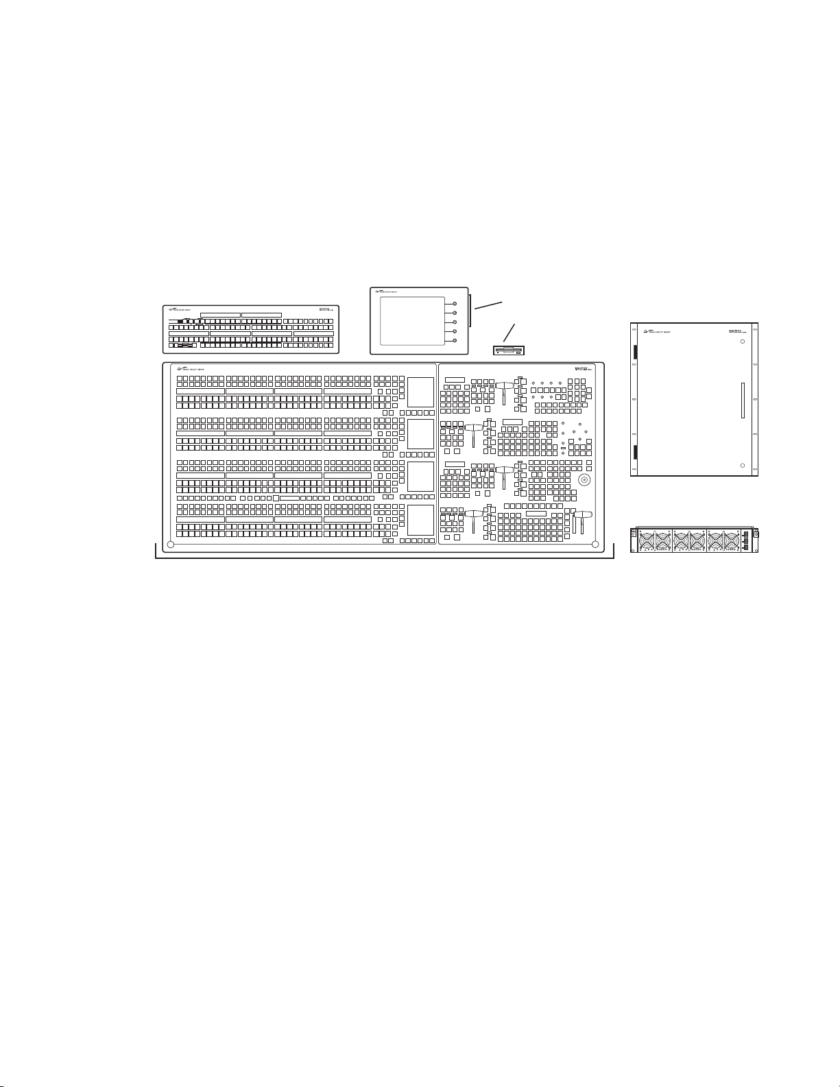
System Components
4-M/E
Main Panel
Video Processor Frame
Video Processor
Power Supply Frame
Local Aux Panel
Menu Panel
Control Surface
Removable
Media
Drives
Bypass Active
Assign
Emergency
Bypass
Select Source
A Kalypso System consists of a Control Surface comprised of two or more
control panels, a Video Processor frame, Video Processor Power Supply,
and removable media drives. Several of the standard 4-M/E system components depicted in Figure 1 are also common to 2-M/E systems. Remote
Aux panels and accessory satellite panels are available as options.
Figure 1. 4-M/E Kalypso System Components
System Components
Control Surface
The modular design of Kalypso control panels provides flexibility for
mounting component panels in various environments, and allows the
addition of specialized accessory control panels. A group of panels available to a single operator is called a Control Surface. A single Kalypso Video
Production Center may have multiple Control Surfaces, allowing more
than one operator to control some or all of the Kalypso system.
A Control Surface consists of at least two components, a Main panel and a
Menu panel. The 4-M/E has a separate Local Aux panel, while the 2-M/E
has a Local Aux subpanel integrated into the Main panel. A 1-M/E control
surface is designed to operate in conjunction with a 4-M/E or 2-M/E Main
panel as an accessory workstation (refer to Figure 2).
Kalypso — User Manual 25
Page 26
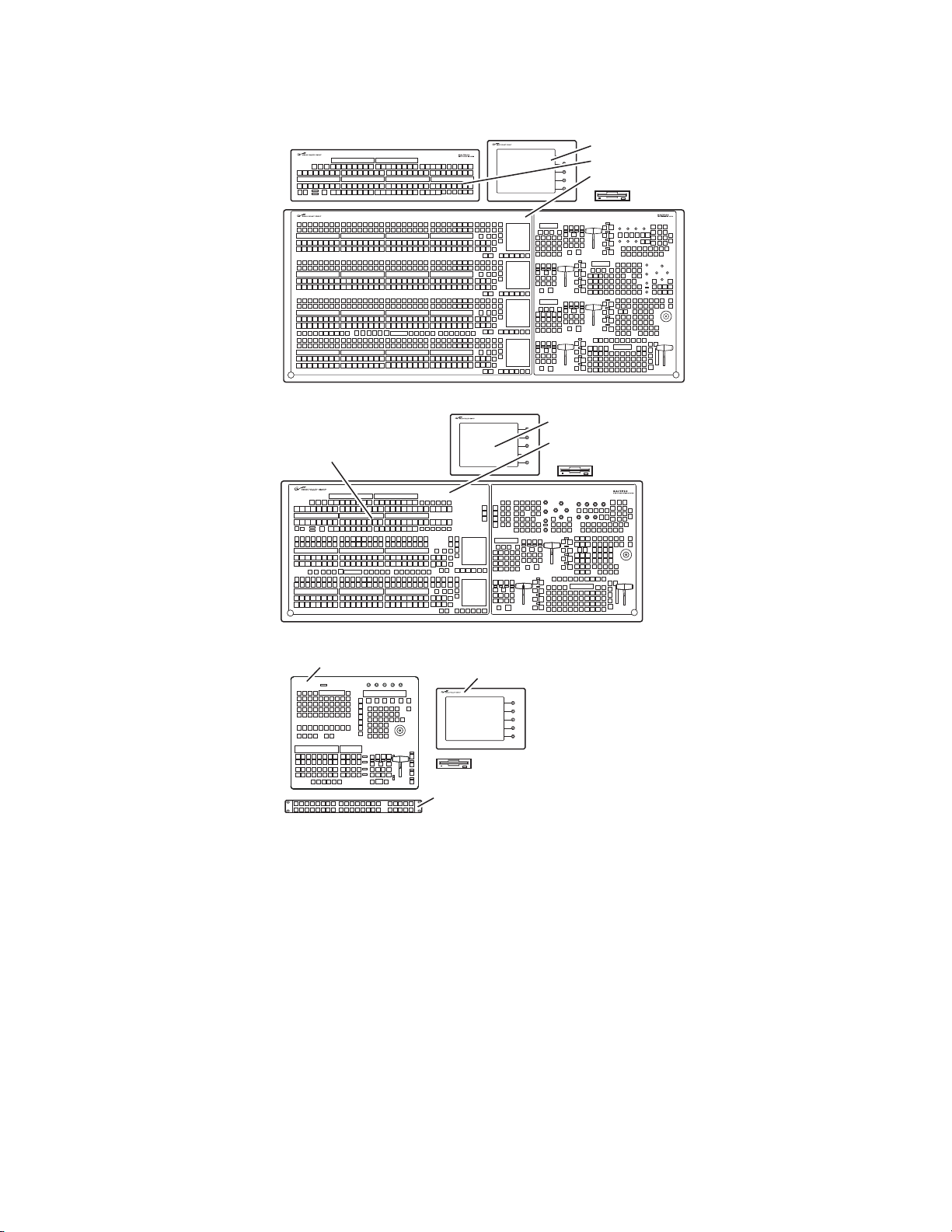
Section 1 — System Overview
0619_08_84_r1
1-M/E Main Panel
Menu Panel
(option)
Remote Aux Panel
(option)
Zip Drive
(customer supplied option)
0619_08_73_r1
Menu Panel
Local Aux Panel
4-M/E Main Panel
Zip Drive
Figure 2. Kalypso Control Surface
Local Aux Panel
Integrated into
2-M/E Main Panel
Menu Panel
2-M/E Main Panel
Zip Drive
0619_08_74_r1
26 Kalypso — User Manual
Page 27
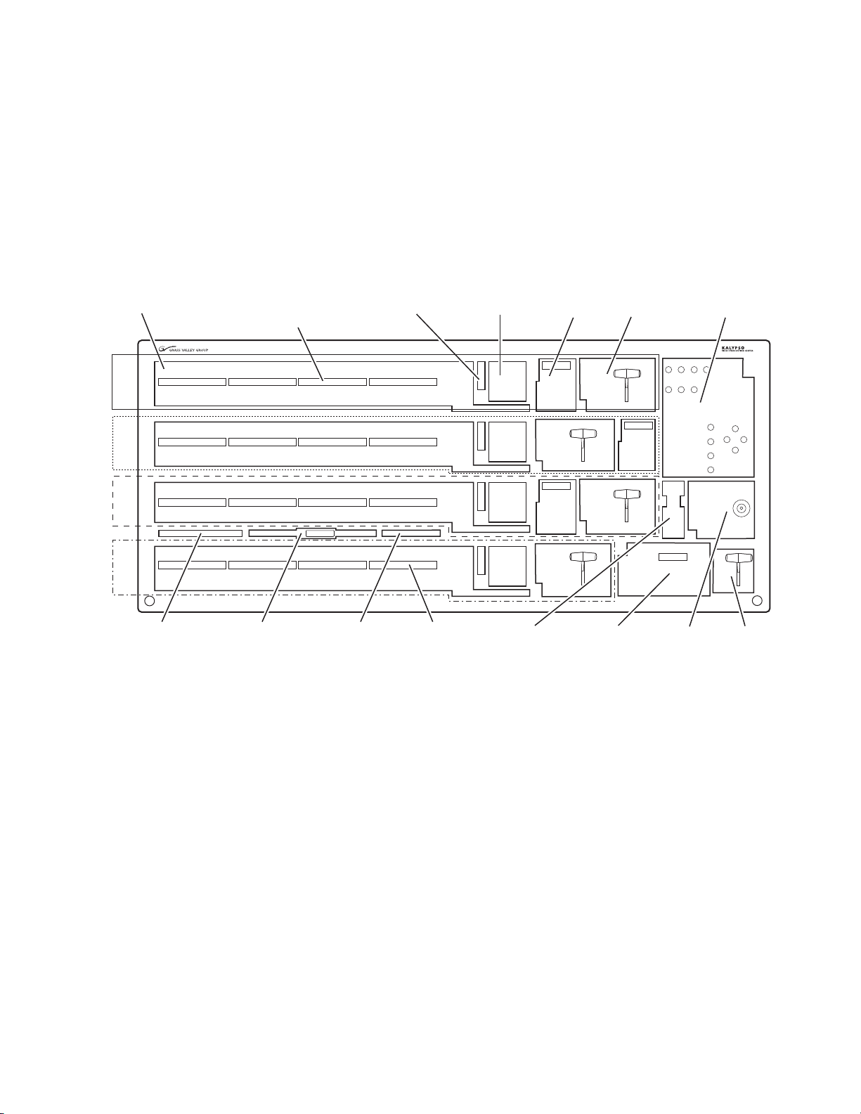
4-M/E Kalypso System
0618_00_16_r7
Source
Selection (4)
M/E Status
Displays (4)
E-MEM
Subpanels (3)
M/E
1
Master E-MEM
Subpanel
Effects Run
Subpanel
Transition
Subpanels (4)
M/E Modifiers
Subpanel
M/E Source Name
Displays (3)
(option)
PGM/PST
Source Name
Display (standard)
Macros
Subpanel
Machine Control
Subpanel
Preview
Subpanel
Transform
Subpanel
Effects Edit
Subpanel
M/E
2
PGM
PST
M/E
3
M/E Keyer
Delegation (4)
4-M/E Main Panel
The Main panel provides real time button, knob, and lever arm control of
the Kalypso system. The panel is organized into subpanels that contain
groups of related controls (Figure 3).
Figure 3. Kalypso 4-M/E Main Panel
System Components
Connections to the Kalypso Processor and to other components of the
Kalypso Control Surface are located on the rear of the Main panel
(Figure 6).
Kalypso — User Manual 27
Page 28
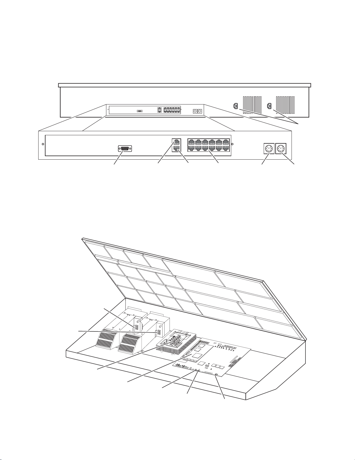
Section 1 — System Overview
Menu Panel
Power
Local Aux Bus
Power
Panel
Diagnostic
Panel
LAN
Satellite Control
Panels (12)
Not
Used
AC In
8162_00_02_r0
0618_06_140_r0
S
A
TELLITE POR
TS
TRANSMIT
RECEIVE
8
8
8
8
8
8
8
8
TRANSMIT
GP8
GP7
GP6
GP5
GENERAL
P
U
RPOSE
LEDS
GP4
GP5
GP1
GP0
RECEIVE
SA
T
E
LLI
T
E P
O
R
T
S
F
AU
L
T
INIT
R
UN
XM
T
C
1
19
RC
V
LINK
R
TP
/CONTR
OL P
AN
E
L L
AN
A
CT
IVITY
COL
N
C
29
3
.
3V
R1
5
1
R
1
5
2
POWE
R
S
U
P
P
LI
ES
M
E
NU
P
R
OCESSOR
RESE
T
R15
3
5
V
1
2
V
SCSI
H
A
R
D
DI
S
K
5
6
7
8
9
0
1
2
3
4
Real Time (RT)
Processor
(with Disk on Chip)
Power Distribution
Board
Primary
Power Supply
On/Off Switch
Redundant
Power Supply
On/Off Switch
Main Panel
Reset Button
Menu Panel
Reset Button (inactive)
Main Panel
Boot Dial Switch
Two models of 4-M/E Main panel exist. Late model designs shipping at the
time of this manual’s publication have the connections shown in Figure 4.
This model Main panel works with the Enhanced Menu panel.
Figure 4. Late Model 4-M/E Main Panel, Rear View
Main panel power switches and the Main panel reset button are accessed
by lifting the top of the Main panel (Figure 5). A redundant power supply
can be installed into the tub of the Main panel as an option. The Main panel
provides power to the separate Menu panel and Local Aux panel.
Figure 5. Late Model 4-M/E Main Panel Inside View
28 Kalypso — User Manual
Page 29
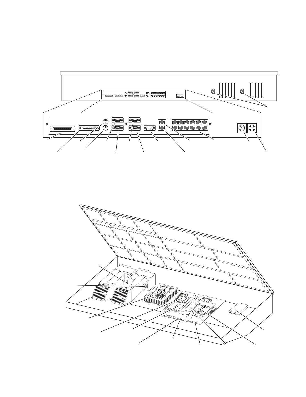
System Components
Menu Panel
Power
Local Aux Bus Power
(* Inactive on modified panels.)
SCSI*
Parallel
Port*
Mouse*
Keyboard*
Menu
Touchscreen*
Menu
Diagnostic*
Panel
Diagnostic
Panel
LAN
Menu Display
SVGA Video Out*
Satellite Control
Panels (12)
Facility
LAN*
Menu
Controls*
AC In
0618_06_142_r0
SATELLITE POR
TS
TRANSMIT
RECEIVE
8
8
8
8
8
8
8
8
TRANSMIT
GP8
GP7
GP6
GP5
GENER
AL
PURPOSE
LEDS
GP4
GP5
GP1
GP0
RECEIVE
SAT
EL
LIT
E
POR
T
S
FA
U
LT
INIT
RUN
XM
T
C119
R
C
V
LIN
K
RTP
/CONTR
O
L
P
ANEL
LA
N
AC
T
IV
I
T
Y
CO
L
N
C
2
9
3.3V
R15
1
R152
P
O
WER S
UP
PLIES
MENU
PROCESSO
R
RESE
T
R153
5V
12
V
SCS
I
HAR
D
DIS
K
5
6
7
8
9
0
1
2
3
4
0618_06_95_r6
Power Distribution Board
Real Time (RT)
Processor
Real Time (RT)
Processor Hard Drive
(may not be present)
Floppy Disk
Drive
NT Hard Drive
Menu (NT)
Processor
Primary
Power Supply
On/Off Switch
Redundant
Power Supply
On/Off Switch
Main Panel
Reset Button
Menu Panel
Reset Button
Main Panel
Boot Dial Switch
Earlier model 4-M/E Main panels have additional connectors (Figure 6)
used with the original Kalypso Menu panel. If this model is modified for
Enhanced Menu panel operation, the indicated connectors are inactive.
Figure 6. Early Model 4-M/E Main Panel, Rear View
The early model Main panel power switches, reset buttons, and floppy
drive are located under the Main panel lid (Figure 7).
Figure 7. Early Model 4-M/E Main Panel Inside View
Kalypso — User Manual 29
Page 30
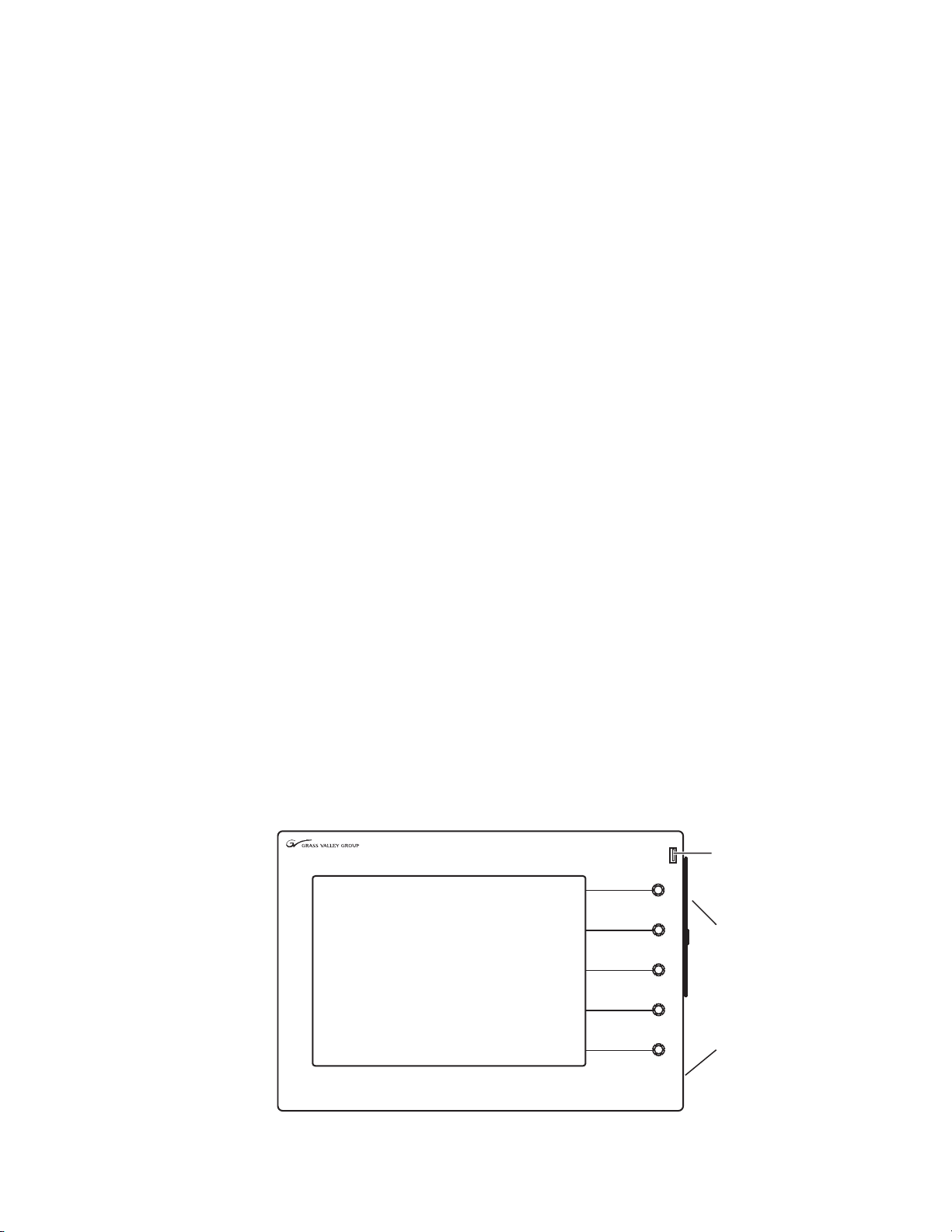
Section 1 — System Overview
Fan
CD-ROM
USB Port
The actual type and location of equipment installed in early model Main
panels varies, depending on date of manufacture. Some earlier designs
used Hard Disk drives with the Real Time (RT) processor, and some used
Disk on Chip hardware. Also, drives may be mounted directly on the processor boards or on separate brackets. If modified for Enhanced Menu
panel operation, unnecessary hardware is removed and some rear connectors become inactive.
Regardless of the equipment involved, the various model Kalypso systems
generally operate identically, except late model systems do not have floppy
disk drives.
Menu Panel
The Menu panel provides access to additional system controls that generally do not require real time adjustment. The Menu panel can be installed
above or to either side of the Main panel, and should be oriented so the
screen directly faces the operator. Additional Menu panels can also be configured with a Kalypso Control Surface.
Two models of Kalypso Menu panel exist, the Enhanced Menu panel and
the Original Menu panel. The Enhanced Menu panel operates with late
model Main panels (or modified early model panels). The Original Menu
panel only works with unmodified early model Main panels.
The Enhanced Menu panel (Figure 8) includes a touch screen display, five
knobs for adjusting parameter values, a cooling fan, and an internal
CD-ROM drive. This model houses the Menu System Processor and runs
the Windows XP operating system.
Note There are two versions of the Enhanced Menu Panel. The newer version (as
shown in
and Windows XP installed. The older version has both USB ports on the rear
of the Menu panel and Windows 2000 installed.
Figure 8. Enhanced Menu Panel, Front View
Figure 8) has the second USB port on the front of the Menu panel
30 Kalypso — User Manual
Page 31

System Components
Hold to
Learn
MenuMenu MenuMenu MenuMenu
MenuMenu MenuMenu
MenuMenu MenuMenu
MenuMenu
E-MEME-MEM
Stilltill
StoreStore
T-formT-form
MatteMatte
WipeWipeKeyerKeyer
M/M/E
Time-
Time-
lineline
CopyCopy
SwapSwap
DailyDaily
SetupSetup
OtherOther
ApsAps
FileFile
OpsOps
StatusStat us
AuxAux
BusBus
MacroMacro
R-MEMR-MEM
ExtExt
DevDev
P-BusP-Bus
Touch Screen
Display
Soft Knobs (5)
Last Menu
Button (1)
Menu Selection
Buttons (21)
0618_00_18_r6
Programmable
Menu Buttons (8)
Ports located on the rear of the Menu panel (Figure 9) provide connections
to the Main panel, Video Processor frame, an external Zip drive, a PS/2
mouse and keyboard, and other devices.
Figure 9. Enhanced Menu Panel, Bottom View of Connectors
= Hole pair for Adaptable Mounting Bracket (5)
*
= Hole pairs (top and bottom) for Flush Mount kit
*
*
*
*
Panel Bottom
COM 4
COM 3
Serial Ports
USB 1
USB Port
The original Kalypso Menu panel (Figure 10) has a touch screen display
and knobs for adjusting parameter values, and also includes Menu Selection buttons on the left. This model Menu panel runs the Windows NT
operating system.
Alternative Four Hole Pattern for
Adjustable Freestanding Console Bracket
or Articulated Arm
MOUSE KEYBOARD
RESET
PS/2 Mouse/Keyboard
Rear of panel
LAN
CROSS
Ethernet Power
Link LED
DC IN
OVER
8096_00_14_r6
Left Side
View
2.5 in.
64 mm
1.6 in.
41 mm
4.3 in.
109 mm
Figure 10. Original Menu Panel, Front View
Kalypso — User Manual 31
Page 32

Section 1 — System Overview
0619_00_15_r6
2.5 in.
64 mm
Bottom
View
Side
View
Without
Mounting
Bracket
1.6 in.
41 mm
3.9 in.
99 mm
8.4 in.
213 mm
Touch Screen ControlMenu ControlsSVGA Video
DC Power In
The Menu System Processor for these models resides in the Main panel,
and so extra connections are required for operation (Figure 11).
Figure 11. Original Menu Panel, Bottom View of Connectors
Power Cabling
The Menu panel normally receives its power from the Main panel. An
optional brick style external power supply is available that allows the
Menu panel to be powered independently from the Main panel (Figure 12).
This same type of power supply can be used with the Local Aux panel.
Figure 12. Optional External Power Supply
Local Aux Panel
0619_07_02_r0
The Local Aux panel provides control of the Kalypso System Aux buses,
Still Store source selection, some switched preview, and also supports
32 Kalypso — User Manual
Page 33

System Components
Bypass Active
Assign
Emergency
Bypass
Select Source
KeyKey
1
KeyKey
2
AuxAux
1
AuxAux
2
AuxAux3AuxAux4AuxAux5AuxAux6AuxAux
7
BypassBypass
DelegDeleg
BypassBypass
EnableEnable
Switcher
Router
RouterRouter
AssignAssign
NextNext
PagePage
PrevPrev
PagePage
GangGang
SelectSelect
AuxAux1AuxAux2AuxAux3AuxAux4AuxAux
5
AuxAux
6
AuxAux
7
AuxAux
8
AuxAux
9
AuxAux
1010
AuxAux
1111
AuxAux
1212
StillStill
StoreStore
AuxAux
1313
PVWPVW
PriPri
M/E1M/E
2
M/E3PgmPgm
PstPst
ShiftShift
Un-Un-
ShiftShift
HoldHold
NearNear
SideSide
FarFar
SideSide
KeyKey
SplitSplit
AuxAux8AuxAux9AuxAux
1010
AuxAux
1111
AuxAux
1212
StillStill
StoreStore
AuxAux
1313
PVWPVW
PriPri
M/E1M/E
2
M/E3PgmPgm
PstPst
ShiftShift
Un-Un-
ShiftShift
HoldHold
NearNear
SideSide
KeyKey
SplitSplit
FarFar
SideSide
Source Name
Display (4 segments)
Router
Assignment (3)
Source Select
Bus #2 (32)
Source Select Modifiers (6)
for Bus #2
Aux Bus Status
Display (2 segments)
Emergency Bypass (4)
(option)
Source Select
Bus #1 (32)
Bus #1
Delegation (15)
Bus #2
Delegation (15)
Gang Select
Button
M/E Select
Bus #2 (4)
M/E Select
Bus #2 (4)
Source Select Modifiers (6)
for Bus #1
0618_02_19_r0
1.8 in.
46 mm
1.8 in.
46 mm
3.9 in.
99 mm
8.4 in.
213 mm
Bottom
View
Side
View
Without
Mounting
Bracket
Spare Emergency
Bypass
MixerDiagnostic
Emergency
Bypass
Router
LAN
0618_03_127_r2
Main and Redundant
DC Power In
Local Aux Panel
Boot Dial
(recessed)
Local Aux Panel
Reset Button
Router source selection and Emergency Bypass option operation
(Figure 13).
Figure 13. Kalypso Local Aux Panel
Connections to the Kalypso Main panel are located on the bottom of the
Local Aux panel (Figure 14).
Figure 14. Local Aux Panel, Bottom View of Connectors
The Local Aux panel is generally installed directly above the left side of the
Main panel so the Source Select buttons are aligned, though it can be
mounted in any convenient location.
Kalypso — User Manual 33
Page 34

Section 1 — System Overview
If the Emergency Bypass option is installed, a redundant power supply for
the Local Aux panel is available to ensure bypass operation even if the
Main panel loses power.
Power Cabling
The Local Aux bus is normally powered from the Main panel. The Local
Aux panel can also accept a redundant power source, and/or be powered
separately from the Main panel using the same model optional power
supply available for the Menu panel (see Figure 12 on page 32).
Removable Media Drives
Kalypso HD (only)
Kalypso HD systems ship with a USB Memory Stick, an Enhanced Menu
panel equipped with a USB port in the front, and an internal CD-ROM
drive.
Earlier Model Kalypso Systems
Different Removable Media Drives are provided, depending on the
Kalypso model. Late model Kalypso systems ship with a USB 250 MB Zip
drive that connects to the Menu panel, and a CD-ROM drive built into the
Menu panel. If the Enhanced Menu panel Flush Mount kit is specified, an
external USB CD-ROM drive is included.
Early model Kalypso systems shipped with three removable media drives
which connect to the Main panel. Included are a SCSI CD-ROM drive, a 250
MB Zip drive (which is connected to the SCSI chain via the CD-ROM), and
a standard 1.4 MB 3.5 in. floppy disk drive. The floppy drive is mounted in
the Main panel tub and is not intended for routine user access.
2-M/E Main Panel
The 2-M/E Main panel is similar to the 4-M/E panel (Figure 15). Instead of
3 M/Es and a PGM PST, the 2-M/E Main panel has one M/E bank and one
PGM PST bank, though three M/Es and PGM PST are accessible via delegation. Local Aux Bus control capabilities are also built in as a subpanel.
34 Kalypso — User Manual
Page 35

Figure 15. Kalypso 2-M/E Main Panel
0618_01_87_r0
---- Source Selection ----
Local Aux
Subpanel
M/E Status
Displays (2)
E-MEM
Subpanel
Keyers, Masks
Subpanels
Mattes,
Copy/Swap
Subpanels
Master E-MEM
Subpanel
Effects Run
Subpanel
Transition
Subpanels (2)
----- M/E Modifiers -----
Source Name
Displays (3)
Macros
Subpanel
Machine Control
Subpanel
Preview
Subpanel
Transform
Subpanel
Effects Edit
Subpanel
PGM
PST
M/E
Aux Bus
Status Display
M/E Keyer
Delegation (2)
Bank Delegation
Subpanel
System Components
Two models of 2-M/E Main panel exist. Late model systems operate with
the Enhanced Menu panel, and early model systems operate with the Original Menu panel.
Kalypso — User Manual 35
Page 36

Section 1 — System Overview
Aux Panel
Diagnostic
Emergency
Bypass
Mixer
Emergency
Bypass
Router
Menu Panel
Power
Local Aux Bus
Power
AC In
LAN Redundant
DC Power In
Panel
Diagnostic
Panel
LAN
Satellite Control
Panels (12)
Not
Used
Late model Kalypso 2-M/E Main panels have connectors at the rear that are
identical to those on a late model 4-M/E system, except there are additional
Local Aux panel connections (Figure 16).
Figure 16. Late Model 2-M/E Main Panel, Rear View
Redundant
Power Supply
On/Off Switch
The late model Kalypso 2-M/E Main panel power switches, reset buttons,
and circuit boards (including the Local Aux panel) are accessed by lifting
the top of the Main panel (Figure 17).
Figure 17. Late Model 2-M/E Main Panel, Inside View
Primary
Power Supply
On/Off Switch
Power Distribution
Board
Local Aux
Reset Button
Real Time (RT)
Processor
Main Panel
Reset Button
Boot Dial Switch
S
A
T
E
L
L
I
T
E
P
O
R
T
T
S
R
A
N
S
M
I
T
G
E
N
E
R
A
8
P
L
U
8
R
P
O
8
S
E
8
L
E
D
8
S
8
8
8
G
P
7
R
G
E
P
C
5
E
I
V
G
E
P
5
S
A
G
T
E
P
L
0
L
I
T
E
P
O
R
T
T
R
S
A
N
S
M
I
T
G
P
8
G
P
6
G
P
4
G
P
1
R
E
C
E
I
V
E
Main Panel
4
5
6
3
7
2
8
1
9
0
R
T
P
/
C
O
N
T
R
O
L
A
P
C
A
T
N
I
V
E
L
I
T
L
Y
F
A
A
N
U
L
C
T
1
1
9
I
N
I
T
R
U
P
N
O
W
E
R
S
X
U
M
P
P
T
C
L
2
I
E
9
S
R
C
V
R
1
M
5
E
1
P
N
R
U
L
O
I
N
C
E
K
S
R
S
1
R
O
5
E
2
R
S
C
E
T
O
L
N
R
1
5
3
3
.
3
V
5
V
1
2
V
S
C
S
I
H
A
R
D
D
I
S
K
Menu Panel
Reset Button (inactive)
0618_06_141_r0
36 Kalypso — User Manual
Page 37

System Components
Menu Display Processor
Serial Ports
Aux Panel
SCSI*
Parallel
Port*
Mouse*
Keyboard*
Menu
Touchscreen*
Diagnostic
Emergency
Bypass Mixer
Emergency
Bypass Router
Panel
Diagnostic
Panel
LAN
Menu Display
SVGA Video Out*
Satellite Control
Panels (12)
* Inactive on
modified systems.
Menu Panel
Power
Local Aux Bus
Power
Facility
LAN*
Menu
Controls*
AC In
LAN Redundant
DC Power In
Menu
Diagnostic*
0618_06_94_r4
S
A
T
E
L
L
I
T
E
P
O
R
T
S
T
R
A
N
S
M
I
T
R
E
C
E
I
V
E
8
8
8
8
8
8
8
8
T
R
A
N
S
M
I
T
G
P
8
G
P
7
G
P
6
G
P
5
G
E
N
E
R
A
L
P
U
R
P
O
S
E
L
E
D
S
G
P
4
G
P
5
G
P
1
G
P
0
R
E
C
E
I
V
E
S
A
T
E
L
L
I
T
E
P
O
R
T
S
F
A
U
L
T
I
N
I
T
R
U
N
X
M
T
C
1
1
9
R
C
V
L
I
N
K
R
T
P
/
C
O
N
T
R
O
L
P
A
N
E
L
L
A
N
A
C
T
I
V
I
T
Y
C
O
L
N
C
2
9
3
.
3
V
R
1
5
1
R
1
5
2
P
O
W
E
R
S
U
P
P
L
I
E
S
M
E
N
U
P
R
O
C
E
S
S
O
R
R
E
S
E
T
R
1
5
3
5
V
1
2
V
S
C
S
I
H
A
R
D
D
I
S
K
5
6
7
8
9
0
1
2
3
4
Primary
Power Supply
On/Off Switch
Redundant
Power Supply
On/Off Switch
Power Distribution
Board
Real Time (RT)
Processor
Floppy
Disk Drive
Menu (NT)
Processor
NT Hard Drive
Local Aux
Reset Button
Main Panel
Reset Button
Main Panel
Boot Dial Switch
Menu Panel Reset Button
Early model 2-M/E Main panel rear connectors are shown in Figure 18. If
modified for Enhanced Menu panel operation the indicated connectors are
inactive.
Figure 18. Early Model 2-M/E Main Panel, Rear View
Early model Kalypso 2-M/E Main panel power switches, reset buttons,
floppy drive, and circuit boards (including the Local Aux panel) are shown
in (Figure 19). Modified panels have unnecessary hardware removed.
Figure 19. Early Model 2-M/E Main Panel, Inside View
Kalypso — User Manual 37
Page 38

Section 1 — System Overview
E-MEM
Menu/Joystick Delegate
Transition
Bank Delegate
Source Select Modifiers
K1
K3
K2
K4
A
U1
B
U2
K1
K3
K2
K4
A
U1
B
U2
M/E
1
Mix
Key 4
Key 3
Mix
Bank
Edit
Eff
Detent
Center
Key 2
Mix
Key 1
Mix
Lock
Learn
Master
Undo
Cut
Trans
Auto
Mix
On
Bkgd
Wipe
Sec
1
Key2Key3Key
PVW
Black
Preset
Trig
Trans
4
Key
Prior
Key
On On On
Sec
Sec
Sec
Shift
Shift
Shift
Shift
1
Wipe
2
User
13
UserUser
2
ShiftUnshift
Near
Far
Alt
Key
Split Side Side
Buses
M/E
2
M/E
3
XY Z
M/EM/EM/E
1
2
3
Key
1
3
KeyKey
2
4
Key
F1Up
F2
F3
F4
F5
More
Bkgd
Bkgd
Global Trans
Pgm
Pst
Ext
Menu
1
2
Wipe
Drop
Shdw
Transform
Force
Mask
Keyer Matte
Locate3DSize
Locate
Rotate Src
Target
SpinAxis
Locate
Inhibit
Mask
Post
T-form
Show Macro
Pgm
Pst
Pri
Sec
1
23
4
5
6
7
8
9
0
Clear
Entry
Trans
Rate
Trim
Enter
Run
Rew
Rev
Hold
Inputs
Stop
Next
+/-
M/E
1
M/E
2
M/E
3
Select
All
Delegates
Auto
Recall
Ind
Run
Auto
Run
DelegMacro
Insert Rec
Delay
Post Delete
Attach
Pre Repl
AttachAttach
Attach Show
AttachEnable
Misc
1
Misc
2
Misc
3
Misc
4
Misc
5
Misc
6
Misc
7
Effects
Dis
Seq
Pgm
Pst
DPM
SS
A
SSBSS
C
Space
Space
Source
Selection
E-MEM
Subpanel
Transition
Subpanel
Menu/Joystick
Delegate
Subpanel
M/E Source Name
Display
Bank Delegate
Subpanel
Source Select
Modifiers
Menu
Soft Knobs (5)
Menu Readout
Reset
Button
Macros
Subpanel
1-M/E Main Panel
A 1-M/E Main panel is intended to act as an accessory control surface for
a 4-M/E or 2-M/E Kalypso system, not as the primary system control
point. A 1-M/E Main panel can be used for pre- or post-production, or be
used during live production to permit another operator to assist the TD.
Intended uses for the 1 M/E panel include:
• Effects creation,
• Setup activities away from the main panel,
• Back room editing,
• Preselection and/or upstream effects playout, and
• Branding or other downstream activities.
Though the 1-M/E Main panel has only one M/E control bank, it can be
delegated to control any of the M/Es of a 2 or 4-M/E Kalypso system.
Figure 20. Kalypso 1-M/E Main Panel
The 1-M/E Main panel’s top lid is held closed with screws and is not
designed to be opened by the operator. No user controls or field serviceable
parts reside in the unit.
38 Kalypso — User Manual
Page 39

System Components
AC
LINE 1
AC
LINE 2
LAN SATELLITE
PANEL
DIAGNOSTIC
0 = NORMAL
RESET
COM 1 COM 2
AC
LINE 1
AC
LINE 2
LAN SATELLITE
PANEL
DIAGNOSTIC
0 = NORMAL
RESET
COM 1 COM 2
0
1
5
2
3
4
6
7
8
9
COM 2Reset
Button
Boot Dial
Switch
LAN Satellite
Panel
COM 1AC In
0619_08_88_r1
Green LED
Link/Receive
Yellow LED
Activity
Ground
Lug
The 1-M/E Main panel has a reset button on the rear and one inside the
lever arm slot, to permit easy reset when installed in a console.
Figure 21. Kalypso 1-M/E Main Panel, Rear View
Kalypso — User Manual 39
Page 40

Section 1 — System Overview
KA LYPS O R EMO TE AUX PA NEL
123
45678
9
10 11 12
13
14 15 16
M/E1M/E2M/E3Pgm
Pst
Hold
17 18
19
20 21 22 23 24
25
26 27 28
29
30 31 32
UnShift
Shift
Key
Split
Near
Side
Far
Side
0619_04_58_r3
KA LYPS O R EMO TE AUX PA NEL
123
45678
9
10 11 12
13
14 15 16
M/E1M/E2M/E3Pgm
Pst
Hold
17 18 19
20 21 22 23 24
25
26 27 28
29
30 31 32
UnShift
Shift
Key
Split
Near
Side
Far
Side
AUX
1
AUX2AUX3AUX
4
AUX5AUX6AUX
7
AUX8AUX
9
AUX10AUX11AUX12AUX13AUX14AUX15AUX
16
0619_04_60_r3
Display Area
CAMERA JOYSTICK
OVERRIDE
LAN
0619_04_59_r2
LANCamera Joystick OverrideAC Power
Control Panel Options
Remote Aux Panels
Remote Aux panels provide control of selected Kalypso Aux buses from a
remote location. Two models of 32-Crosspoint Remote Aux panels that
employ Ethernet communications are currently available. Three models of
older 24-Crosspoint Aux panels that use serial communications originally
designed for Model 4000 switchers can also be modified for use with
Kalypso systems. Any combination of these aux panels may be used.
32-Crosspoint Remote Aux Panels
Both 32-Crosspoint Remote Aux panel models are designed to select 64
external sources (32 unshifted and 32 shifted). The 1 RU panel
(KAL-32AUX1) is dedicated to a single bus (Figure 22). The 2 RU panel
(KAL-32AUX2) is multi-destination with 16 bus delegate buttons
(Figure 23).
Figure 22. KAL-32AUX1 (1 RU) Remote Aux Panel
Figure 23. KAL-32AUX2 (2 RU) Remote Aux Panel
Both 32-Crosspoint Panels have the same rear panel layout (Figure 24).
These panels have a built-in power supply and use a standard removable
AC power cable.
Figure 24. 32-Crosspoint Remote Aux Panel Rear View
40 Kalypso — User Manual
Page 41

System Components
11 22 33 44 55 66 77 88 99 1010 111 1 121 2 1313 1414 151 5 1616
ONON
AIRA IR
11 22 33
PgmPg m
PstPs t
M/EM/ E M/EM/ E M/EM/E
1717 181 8 1919 2020 212 1 2222 2323 2424 ShiftSh if t
0619_04_64_r1
101099887766554422 33
11
242423232222
1111
21212020191918181717
161615151313
1212
1414
PstPst
PgmPgm
33
M/EM/E
22
M/EM/E
11
M/EM/EShiftShift
0619_04_67_r1
101099887766554422 33
11
242423232222
1111
21212020191918181717
161615151313
1212
1414
PstPst
PgmPgm
33
M/EM/E
22
M/EM/E
11
M/EM/EShiftShift
3A3A
AuxAux
2A2A
AuxAux
1A1A
AuxAux
9A9A
AuxAuxAuxAux
8A8A
AuxAux
7A7A
6A6A
AuxAux
5A5A
AuxAux
4A4A
AuxAux
AuxAux
4B4B
AuxAux
5B5B3B3B
AuxAux
2B2B
AuxAux
1B1B
AuxAux AuxAux
9B9B7B7B
AuxAux
8B8B
AuxAuxAuxAux
6B6B
0619_04_69_r1
-
+
COMMUNICATIONS
BUS
SHIELD
DC POWER
JOYSTICK OVERRIDE
643216
842
1
842
1
FORCE HIGH TALLY
MODE
TEST
ADDRESS
PANEL
OFF
ON
0619_04_65_r0
DC Power
Test Mode Panel Address and
Force High Tally
Joystick OverrideCommunications Bus
24-Crosspoint Remote Aux Panels
The three 24-Crosspoint panel models are designed to select 48 external
sources (24 unshifted and 24 shifted). The 1 and 2 RU panels (KAL-24AUX1
and KAL-24AUX2) are dedicated to a single bus (Figure 25, Figure 26.) The
3 RU panel (KAL-24AUX3) panel is multi-destination with 18 bus delegate
buttons (Figure 27).
Figure 25. KAL-24AUX1 (1 RU) Remote Aux Panel
Figure 26. KAL-24AUX2 (2 RU) Remote Aux Panel
Figure 27. KAL-24AUX3 (3 RU) Remote Aux Panel
All three 24-Crosspoint panels have the same rear panel layout (Figure 28).
Figure 28. 24-Crosspoint Remote Aux Panel Rear Panel
Kalypso — User Manual 41
Page 42

Section 1 — System Overview
M/E 1M/M/E 2M/M/E 3P/P/P
Misc 1
Misc 2
Misc 3
Misc 4
Misc 5
Misc 6
Misc 7
DPM
SS A
SS B
SS C
All
M/E
1
Page
Auto
Run
Run
0 1 2 3
8 9
11
16
4 5 6 7
15
12
19
M/E
2
M/E
3
24-Crosspoint Remote Aux panels use an external, brick type power supply
(Figure 29).
Figure 29. KAL-24AUX Power Supply
Shot Box Option
The E-MEM Shot Box is a separate panel used to rapidly recall previously
built effects (Figure 30).
0619_04_63_r1
Figure 30. Kalypso Shot Box
M/E
M/E
M/E
M/
Misc 1
Misc 5
16
Misc 2
Misc 3
101011
Misc 6
Misc 7
1717181819
Misc 4
DPM
SS A
12
Page
SS B
SS C
1313141415
Auto
Run
All
Run
0721_07_65_r1
The Shot Box can be powered from the Main panel through the cables provided. If located more than 3 m (10 ft) from the Main panel, an optional Satellite Panel extension kit is available that includes a brick type power
supply.
42 Kalypso — User Manual
Page 43

Kalypso Classic Video Processor Frame
DC POWER
0619_00_02_r9
ON
OFF
Fan Drawer
Power Switch
Slot A1
Control
Module
Slot A5
Still Store
Module (optional)
Air FilterSlot A11 - A14
M/E Modules
(PGM/PST, M/E 1, 2, 3)
Slot A15 - A16
Transform Engine
Modules (2, optional)
Slot A17
Sync Generator
Module
Slots A8 - A10
Crosspoint
Modules (3)
4-M/E Kalypso Classic Video Processor Frame
The Kalypso Classic Video Processor frame houses most of the system electronics, with slots in the front and rear that hold individual modules. The
front bay holds system control, video routing, and signal processing modules. A fully loaded system is shown in Figure 31.
Figure 31. Fully Equipped Kalypso Classic Video Processor Frame Front View, Door Removed
System Components
CAUTION The front door of the Kalypso Video Processor must remain closed during
normal system operation for proper cooling airflow.
Kalypso — User Manual 43
Page 44

Section 1 — System Overview
J4
J3
TIMECODE IN
J2
J1
REFERENCE
REFERENCE
IN
OUT
IN
J6
J4
J5
J8J7
J10J9
2
1
J13J12
54
J16J15
8
J11
3
J14
6
7
422/
CPL
SERIAL
PORTS
GPI
COMM 1
COMM I/O
CONTROL
PANEL
LAN
J1
FACILITY
LAN
J2
STILL
STORE
LAN
J3
SERIAL
OUTPUT
J1
J2
J3
J4
J5
J6
J7
J8
J9
J10
J11
J12
J13
J14
J15
J16
SERIAL
OUTPUT
J1
J2
J3
J4
J5
J6
J7
J8
J9
J10
J11
J12
J13
J14
J15
J16
SERIAL
OUTPUT
J1
J2
J3
J4
J5
J6
J7
J8
J9
J10
J11
J12
J13
J14
J15
J16
SERIAL
OUTPUT
J1
J2
J3
J4
J5
J6
J7
J8
J9
J10
J11
J12
J13
J14
J15
J16
SERIAL
OUTPUT
J1
J2
J3
J4
J5
J6
J7
J8
J9
J10
J11
J12
J13
J14
J15
J16
SERIAL
INPUT
J1
J2
J3
J4
J5
J6
J7
J8
J9
J10
J11
J12
J13
J14
J15
J16
SERIAL
INPUT
J1
J2
J3
J4
J5
J6
J7
J8
J9
J10
J11
J12
J13
J14
J15
J16
SERIAL
INPUT
J1
J2
J3
J4
J5
J6
J7
J8
J9
J10
J11
J12
J13
J14
J15
J16
SERIAL
INPUT
J1
J2
J3
J4
J5
J6
J7
J8
J9
J10
J11
J12
J13
J14
J15
J16
EFFECTS
SEND
J1
J2
J3
J4
J5
J6
J7
J8
J9
J10
J11
J12
J13
J14
J15
J16
1A
1B
2A
2B
3A
3B
4A
4B
SERIAL
INPUT
J1
J2
J3
J4
J5
J6
J7
J8
J9
J10
J11
J12
J13
J14
J15
J16
TALLY
J1
J2
TALLY
J1
J2
J1
DC
INPUT
J3
TIMECODE
IN
J4
ALARM
Slot B17
Reference In
Module
Slots B16-B12
Output Modules (5)
(optional)
Slots B10-B6
Input Modules (5)
(1 standard [B10],
4 optional)
Slots B5-B4
Tally Modules (2)
(1 standard [B5],
1 optional)
Slot B1
Control I/O Module
(3 slots wide)
Slot B11
Effects Send
Module
Air Exhaust
DC Input from
Power Supply
Chassis
Grounding
Lug
CPL
Peripheral
Bus II
Editor
Tal ly
Remote
Aux Panels
The rear bay holds input and output modules and provides reference and
system control connections. A fully loaded system is shown in Figure 32.
Some of the modules illustrated are optional and may not be included in
your Kalypso system. The slots on the rear of the Video Processor frame are
numbered from right to left.
Figure 32. Fully Equipped Kalypso Classic Video Processor Frame, Rear View
The Kalypso system has been designed for easy maintenance. All modules
of the same type are identical, and can be swapped with one another.
Modules can be removed and replaced safely with the power on, simplifying troubleshooting to the module level.
44 Kalypso — User Manual
Page 45

2-M/E Kalypso Classic Video Processor Frame
The 2-M/E Kalypso Classic system uses the same frame hardware as the
4-M/E Kalypso system, except some slots are not filled in the standard configuration. Because only two M/Es are standard (M/E 1 and PGM PST),
only two M/E modules and two crosspoint modules are provided
(Figure 33).
The 2-M/E Kalypso system supports the Still Store and Transform Engine
options, and up to two additional M/E modules can also be added.
Figure 33. Standard 2-M/E Kalypso Video Processor Frame, Front View
System Components
Fan Drawer
Power Switch
DC POWER
ON
OFF
0618_01_85_r3
Slot A1
Control
Module
Air Filter
Slot A5
StillStore
Module (optional)
Slots A8, A10
Crosspoint
Modules (2)
Slot A11 - A12
M/E Modules
(PGM/PST, M/E 1)
Slot A15 - A16
Transform Engine
Modules (2, optional)
Slot A17
Sync Generator
Module
CAUTION The front door of the Kalypso Video Processor must remain closed during
normal system operation for proper cooling airflow.
Kalypso — User Manual 45
Page 46

Section 1 — System Overview
J4
ALARM
J3
TIMECODE IN
J2
J1
REFERENCE
REFERENCE
IN
OUT
IN
J6
J4
J5
J8J7
J10J9
2
1
J13J12
5
4
J16J15
8
J11
3
J14
6
7
422/
CPL
SERIAL
PORTS
GPI
COMM 1
COMM I/O
CONTROL
PANEL
LAN
J1
FACILITY
LAN
J2
STILL
STORE
LAN
J3
SERIAL
INPUT
J1
J2
J3
J4
J5
J6
J7
J8
J9
J10
J11
J12
J13
J14
J15
J16
EFFECTS
SEND
J1
J2
J3
J4
J5
J6
J7
J8
J9
J10
J11
J12
J13
J14
J15
J16
1A
1B
2A
2B
3A
3B
4A
4B
TALLY
J1
J2
DC
INPUT
J1
Slot B17
Reference In
Module
Slot B16
(Output Module 1
is inactive when
Crosspoint 2 Module
is not present)
Slots B15-B12
Output Modules (4)
(option)
Slots B10-B6
Input Modules (5)
(1 standard [B10],
4 optional)
Slots B5-B4
Tally Modules (2)
(1 standard [B5],
1 optional)
Slot B1
Control I/O Module
(3 slots wide)
Slot B11
Effects Send
Module
Air Exhaust
DC Input from
Power Supply
0618_01_86_r3
Chassis
Grounding
Lug
CPL
Peripheral
Bus II
Editor
Tally
Remote
Aux Panels
The standard 2-M/E Kalypso system includes one Input module and the
Effects Send module to support video inputs and outputs (Figure 34). Up
to four additional Input and Output modules can be installed. Slot B16
(labeled on the frame as Output 1, 1-8) is not available for use on a standard
2-M/E Kalypso system.
Figure 34. Standard 2-M/E Kalypso Video Processor Frame, Rear View
46 Kalypso — User Manual
Page 47

Kalypso Classic M/E Module Control Assignments
Tab le 1 shows how the Main panel banks are assigned to M/E modules in
a factory configured Kalypso Classic Video Processor frame.
Table 1. Banks and M/E Module Locations
Video Processor
Frame Slot
Bank 4-M/E 2-M/E
PGM PST A 11 A 11
M/E 1 A 12 A 12
M/E 2 A 13 -
M/E 3 A 14 -
2-M/E Kalypso Classic systems ship with only two M/E modules standard, for control by the PGM PST and M/E 1 banks. Adding M/E modules
in the slots listed allows delegated control of the added M/Es. An additional Crosspoint module in slot A9 is also required.
System Components
Note The Resource Sharing feature permits the logical assignment of any Main
panel bank to any physical M/E.
Kalypso — User Manual 47
Page 48

Section 1 — System Overview
0619_08_76_r3
OFF
ON
Fan Drawer
Keyboard*
VGA Port*
Floppy Disk
Drive*
* For Service
Personnel
Use Only
Control
Processor
Power
Switch
Frame Reset
Button
COM Boot
Dial
Slot 1
Control
Module
Slot 2
Still Store
Module
(optional)
Air Filter Slot 4 - 7
M/E Modules
(M/E 3, 2, 1, PGM/PST)
Slot 8 - 9
Transform Engine
Modules (2)
(optional)
Slots 3
Crosspoint
Module
Kalypso HD/Duo Video Processor Frame
The Kalypso HD Video Processor frame houses most of the system electronic. Slots in the front hold system control, video routing, and signal processing modules. A fully loaded system is shown in Figure 35. 2-M/E
Kalypso systems ship with only 2 M/E modules, and the Still Store and
Transform Engine modules are optional.
Figure 35. Fully Equipped Kalypso Video Processor Frame Front View, Door Removed
CAUTION The front door of the Kalypso Video Processor must remain closed during
normal system operation for proper cooling airflow.
48 Kalypso — User Manual
Page 49

System Components
Air Exhaust
15 Standard Inputs
(with up to 5
15 Input options
for 90 inputs total)
48 Programmable
Outputs
(24 2-M/E
48 4-M/E)
DC Input from
Power Supply
SD Reference
Looping Input
HD Reference
Looping Input
Ethernet LAN
Connections
(6 external ports)
0619_08_77_r1
2 HDLC Serial
Connectors for
CPL Interface
Diagnostic Port
Timecode Reader
Input
GPI In
GPI Out
Tally 1-32
Tally 33-64
Outputs
Inputs
LAN
Timecode
In
SD HD
Analog Reference In
DC In
GPI In
Serial 5 Serial 6 Serial 7 Serial 8
Serial 1 Serial 2 Serial 3 Serial 4
Diagnostic HDLC 1 HDLC 2
GPI Out
Tally
1-32
Tally
33-64
1
1
2
3
4
5
6
7
8
9
10
11
12
13
14
15
16
17
18
19
20
21
22
23
24
25
26
27
28
29
30
31
32
33
34
53
36
37
38
39
40
41
42
43
44
45
46
47
48
49
50
51
52
53
54
55
56
57
58
59
60
61
1
23
4
56
62
63
64
65
66
67
68
69
70
71
72
73
74
75
76
77
78
79
80
81
82
83
84
85
86
87
88
89
90
2
3
4
5
6
7
8
9
10
11
12
13
14
15
16
17
18
19
20
21
22
23
24
25
26
27
28
29
30
31
32
33
34
35
36
37
38
39
40
41
42
43
44
45
46
47
48
8 configurable
Serial Ports for
Editor,
Peripheral Bus II, and
Remote Aux Panels
Chassis
Grounding
Lug
The rear of the Video Processor frame has input and output connectors and
provides reference and system control connections (Figure 36).
Figure 36. Kalypso Video Processor Frame, Rear View
The Kalypso system has been designed for easy maintenance. All modules
of the same type are identical, and can be swapped with one another.
Modules can be removed and replaced safely with the power on, simplifying troubleshooting to the module level.
Kalypso — User Manual 49
Page 50

Section 1 — System Overview
8218_06_15_r0
Power Supply Modules (3)
2 Standard, 1 Option
Power Supply
Locking Screw(s)
J3PS3 J2PS2 J1PS1
DC OUTPUT
A1
A2
A3
J10
DC Output to Video Processor Frame AC Power (3)
Chassis
Grounding Lug
Kalypso Video Processor Power Supply
A separate Video Processor Power Supply provides power to the Kalypso
Video Processor. The Video Processor Power Supply frame holds up to
three Video Processor Power Supply modules (Figure 37). Two modules are
required for system operation. The third module is an optional backup.
Power supply modules can be installed in any slot in the Video Processor
Power Supply frame.
Figure 37. Kalypso Video Processor Power Supply, Front View
Power connectors are located on the rear of the Video Processor Power
Supply (Figure 38), including a special connector for feeding power to the
Video Processor. Each module has its own power connection. Though not
required, we recommend each module be plugged into a separate AC circuit.
Figure 38. Kalypso Video Processor Power Supply, Rear View
50 Kalypso — User Manual
Page 51

Original Kalypso Video Processor Power Supply
Two modules are required for system operation. The third module is an
optional backup. A locking bracket can be slid down to secure the modules
in their slots.
Figure 39. Kalypso Video Processor Power Supply, Front View
VADJ
ACG
DCG
20 40 60 80
100%
VADJ
ACG
DCG
20 40 60 80
100%
System Components
ON
PS1
DC
OFF
ON
PS2
DC
OFF
ON
PS3
DC
VADJ
ACG
DCG
20 40 60 80
100%
OFF
Module
Locking Bracket
Power Supply Modules (3)
2 Standard, 1 Option
Power Supply Module
Power Switches (3)
Though not required, we recommend each module be plugged into a separate AC circuit.
Figure 40. Kalypso Video Processor Power Supply, Rear View
J3PS3 J2PS2 J1PS1
AC Power (3)
Chassis
Grounding Lug
DC Output to Video Processor Frame
DC OUTPUT J10
0618_00_28_r0
0619_00_12_r4
Kalypso — User Manual 51
Page 52

Section 1 — System Overview
Video Processor Frame Options
Still Store Option
The Kalypso Still Store is used to grab, save, and display images. Still Store
features include:
• Instant access to non-volatile stills (fixed names “Still 1”, “Still 2”, etc.),
• Up to 1800 full frame images,
• Full frame grab,
• Partial frame (fenced) grab
• Image positioning and cropping,
•Animation,
• Display entire frame, or on interlaced formats display each field with
• Video key pairs,
either field interpolation or replication,
• Grabbed images can be placed in output (and cached) or saved to hard
disk,
•Thumbnails,
• Eight outputs that can be used independently,
• Preview bus shows Still Store output #8,
• E-MEM control of still output loading, and
• Machine Control subpanel control of still output loading.
An additional KlipCache memory option is also available to increase the
storage capacity of the Still Store cache.
Sources to be captured are selected on the Local Aux panel. That source can
then be grabbed, repeatedly if necessary until the desired image is caught.
The captured image is then saved to the Still Store hard disk. Any still
image can be assigned to any of the eight Still Store outputs. These outputs
are internal Kalypso system sources, which can be mapped to any desired
source select buttons.
Transform Engine Option
The Kalypso Transform Engine option provides 3-D planar image translation and transformation from within the Kalypso system. Each Transform
Engine module houses three Transform Engines. Up to two Transform
Engine modules can be installed in a Kalypso system, permitting manipulation of six video and key pairs at the same time. A Global channel is also
available on each M/E for easy control of complicated transforms. The
52 Kalypso — User Manual
Page 53

System Components
Kalypso system uses its Effects Send feature to supply translation and
transformation capabilities to any keyer on any M/E.
Transform Engine features include:
• Source and Target space selection,
• 3-D Locate, Size Locate, Rotate, Spin, Locate Axis,
• Anti-alias filtering control through transform parameters,
• Aspect, Skew, Perspective,
• Post Transform,
• Global channel on each M/E and PGM PST, to which the Transform
Engine channels in that M/E can be individually assigned,
• Raster Cropping,
• E-MEM keyframe control,
• Near/Far & Front/Back, with horizontal and vertical reverse selection,
and
• Tally (performs on screen/off screen and front/back calculations to
tally only on air images).
An additional software enabled Kurl/Splits and Mirrors Transform Engine
optional feature is also available.
Kalypso — User Manual 53
Page 54

Section 1 — System Overview
Program
Monitor
Preview
Monitor
Other
Monitors
Program Out
Master Control/
Transmitter
Video/Key (Effects Send)
Facility
Router
Frame
Cam 1
Cam 2
Cam 3
Video
Facility Router
Control
Camera
Shader
Video/Key (Effects Return)
Synchronous Serial (CPL)
NOTE: External Effects Send
only on Kalypso Classic
Serial
Reference
Black
Aux Bus Outputs
Profile
VDR
Facility LAN
32-Crosspoint
Remote Aux Panel
Remote Control Surface #1
0618_00_17_r13
Video/Key
Kalypso Main Control Surface
Kalypso Control
Ethernet
Hub
32-Crosspoint
Remote Aux Panel
Remote Control Surface #2
Remote Control Surface #3
24-Crosspoint
Remote Aux Panel
Monitor
Monitor
Serial
LAN
Ethernet
Switch
Shot Box
Kalypso
Video
Processor
Frame
Joystick
DPM
1
VTR
1
Compatible DVEs: Krystal, GVeous/Dveous
Video or Key Signal
Control Line
Override
Kalypso Facility Example
A simplified diagram of a small live studio is shown in Figure 41. In this
facility the Kalypso Video Production Center has control of a portion of the
facility router for pre-selecting various sources into the switcher. The
camera control operator is able to remotely control a Kalypso Aux bus for
selecting camera views to shade. A Profile VDR operator also remotely controls an Aux bus for recording selected iso cameras. After the clips have
been recorded to the Profile, the Technical Director at the Kalypso Main
panel can select and roll the Profile clips from his location. This facility also
has a Krystal DPM system configured for Effects Send. The Technical
Director can recall and run DPM effects from the Kalypso Main panel.
Figure 41. Basic Live Production Studio System Configuration Example
54 Kalypso — User Manual
Page 55

Functional Overview
Internal Control
Still Store LAN
Facility LAN
Facility LAN
Facility LAN
16 GPI In
16 GPI Out
8 Serial
Tally (Relay)
Kalypso Video Processor Frame
2 Synchronous Serial
Control
System
Boot
Config BU
Flash
Tally
Hard
Drive
Still Store
Hard
Drive
Remote Control Surface #3
24-Crosspoint
Remote Aux Panel
32-Crosspoint
Remote Aux Panel
Video or Key Signal
Control Line
Suite Boundary
Control Surface Boundary
USB
USB
To networked
image sources
Ethernet
Hub
NOTES:
Control Panel, Facility, Still Store LAN: 10Base-T or 100Base-T Ethernet
Remote Aux Panels and Still Store are system options.
Point to Point Serial
Ports 1-12
RS-422/Serial Async
Local Aux Panel
Main Control Surface
Remote Control Surface #1
Kalypso Suite (Four Control Surfaces)
Remote Control Surface #2
32-Crosspoint
Remote Aux Panel
LAN
Ethernet
Switch
Shot Box
(Provided with Flush
Mount bracket.)
4-M/E
Main Panel
Menu Panel
Hard
Drive
CD-ROM
Drive
Optional Keyboard
Optional Mouse
Zip Drive
Menu
System
Processor
(Win 2000)
Optional CD-ROM
Real Time
Processor
Optional
Future Satellite
Panels (1-12)
1-M/E
Main Panel
(option)
Real Time
Processor
Kalypso System Control
System control for the Kalypso Video Production Center is designed for
flexibility and simplicity. Ethernet and other standard data interfaces are
used for system component interconnections. Multiple hard disks are
included to permit storage of large numbers of data files. An OS drives the
Menu panel touch screen, which is an SVGA monitor.
Late model 4-M/E Kalypso system control is shown in Figure 42.
Figure 42. Late Model 4-M/E Kalypso Control
Functional Overview
Kalypso — User Manual 55
Page 56

Section 1 — System Overview
Internal Control
Still Store LAN
Facility LAN
16 GPI In
16 GPI Out
8 Serial
Tally (Relay)
Kalypso Video Processor Frame
2 Synchronous Serial
Control
System
Boot
Config BU
Flash
Tally
Hard
Drive
Still Store
Hard
Drive
Remote Control Surface #3
24-Crosspoint
Remote Aux Panel
32-Crosspoint
Remote Aux Panel
32-Crosspoint
Remote Aux Panel
To networked
image sources
LAN
Ethernet
Switch
Ethernet
Hub
Remote Control Surface #1 Remote Control Surface #2
Kalypso Suite (Four Control Surfaces)
Shot Box
Facility LANFacility LAN
Video or Key Signal
Control Line
Suite Boundary
Control Surface Boundary
USB
USB
NOTES:
Control Panel, Facility, Still Store LAN: 10Base-T or 100Base-T Ethernet
Remote Aux Panels and Still Store are system options.
Point to Point Serial
Ports 1-12
RS-422/
Serial Async
Main Control Surface
(Provided with Flush
Mount bracket.)
2-M/E
Main Panel
Menu Panel
Hard
Drive
CD-ROM
Drive
Optional Keyboard
Optional Mouse
Zip Drive
Menu
System
Processor
(Win 2000)
Optional CD-ROM
Real Time
Processor
Optional
Future Satellite
Panels (1-12)
Local Aux Panel
Additional
Menu Panel
(option)
Hard
Drive
CD-ROM
Drive
Menu
System
Processor
(Win 2000)
Late model 2-M/E Kalypso system control is the same as the 4-M/E
Kalypso system, except the Local Aux panel is built into the 2-M/E Main
panel (Figure 43).
Figure 43. Late Model 2-M/E Kalypso Control
56 Kalypso — User Manual
Page 57

Functional Overview
Internal Control
Still Store LAN
Facility LAN
16 GPI In
16 GPI Out
8 Serial
Tally (Relay)
Kalypso Video Processor Frame
2 Synchronous Serial
Control
System
Boot
Config BU
Flash
Tally
Hard
Drive
Still Store
Hard
Drive
Remote Control Surface #3
24-Crosspoint
Remote Aux Panel
32-Crosspoint
Remote Aux Panel
Video or Key Signal
Control Line
Suite Boundary
Control Surface Boundary
Button Knob Control (Serial)
Touch Screen Control (Serial)
SVGA
SCSI
SCSI
Optional Keyboard
Optional Mouse
Menu
Panel
CD-ROM
Zip Drive
Optional
Future Satellite
Panels (1-12)
To networked
image sources
Ethernet
Hub
NOTES:
Control Panel, Facility, Still Store LAN: 10Base-T or 100Base-T Ethernet
Button Knob and Touch Screen Control: RS-232 Serial Async
Remote Aux Panels and Still Store are system options.
4-M/E
Main Panel
Point to Point Serial
Ports 1-12
RS-422/Serial Async
Internal
Control
0618_00_03r14
Local Aux Panel
Main Control Surface
Remote Control Surface #1
Kalypso Suite (Four Control Surfaces)
Hard
Drive
3.5"
Drive
Menu
System
Processor
(Win NT)
Real Time
Processor
Remote Control Surface #2
32-Crosspoint
Remote Aux Panel
LAN
Ethernet
Switch
Shot Box
Early model Kalypso system control is shown in Figure 44 (4-M/E system)
and Figure 45 (2-M/E system).
Figure 44. Early Model 4-M/E Kalypso Control
Kalypso — User Manual 57
Page 58

Section 1 — System Overview
Figure 45. Early Model 2-M/E Kalypso Control.
To networked
image sources
Shot Box
Kalypso Suite (Four Control Surfaces)
Remote Control Surface #1 Remote Control Surface #2
32-Crosspoint
Remote Aux Panel
Main Control Surface
Zip Drive
CD-ROM
Optional Keyboard
Optional Mouse
Menu
Panel
SCSI
Button Knob Control (Serial)
Touch Screen Control (Serial)
Ethernet
Hub
SCSI
SVGA
LAN
Ethernet
Switch
2-M/E
Main Panel
Menu
System
Processor
(Win NT)
Still Store LAN
Tally (Relay)
16 GPI In
16 GPI Out
8 Serial
2 Synchronous Serial
Facility LAN
32-Crosspoint
Remote Aux Panel
Local Aux Panel
Internal
Control
Hard
Drive
3.5"
Drive
Real Time
Processor
Kalypso Video Processor Frame
Control
System
Boot
Config BU
Flash
Hard
Drive
Remote Control Surface #3
Tally
Internal Control
Still Store
Hard
Drive
24-Crosspoint
Remote Aux Panel
Point to Point Serial
Ports 1-12
RS-422/Serial Async
Optional
Future Satellite
Panels (1-12)
NOTES:
Control Panel, Facility, Still Store LAN: 10Base-T or 100Base-T Ethernet
Button Knob and Touch Screen Control: RS-232 Serial Async
Remote Aux Panels and Still Store are system options.
Video Signal Flow
The Kalypso Video Production Center has been designed for operational
flexibility. This is reflected in the basic system architecture. For example, all
the outputs from every M/E are routed back to the video crosspoint matrix,
making all these signals accessible to the entire system (see Figure 46 and
Figure 47 for Kalypso Classic and Figure 48 for Kalypso HD). The only
exception is Effects Send, where the outgoing signal is routed directly to its
internal or external destination.
The Kalypso system does not have any dedicated inputs or outputs (except
Black and Test outputs on Kalypso Classic systems). The inputs and
outputs of the system can be assigned as needed. For example, after
defining the program, preview, and any other necessary signal outputs, all
the remaining outputs can be configured as Aux buses.
Video or Key Signal
Control Line
Suite Boundary
Control Surface Boundary
0721_02_05_r6
58 Kalypso — User Manual
Page 59

0618_01_01_r2
Key 1 Keyer/
Chromakeyer
Borderline
InternalExternalExternal
Borderline
Borderline
Borderline
Key 2 Keyer/
Chromakeyer
Key 3 Keyer/
Chromakeyer
Key 4 Keyer/
Chromakeyer
Video Processor
Video Processor
Video Processor
Video Processor
Effects Send Switch
Key 1 Fill
Key 1 Cut
Key 2 Fill
Key 2 Cut
Key 3 Fill
Key 3 Cut
Key 4 Fill
Key 4 Cut
Bkgnd A
Bkgnd B
Utility 1
Utility 2
Program D
Preview A
Preview 2
Program A
Program B
Program C
Wipe Pattern
Generators
2 Complex, 4 Simple
M/E 1
Standard
1
M/E 2 Inputs
M/E 3 Inputs
PGM/PST
Inputs
2
3
4
5
6
7
8
9
10
11
12
13
14
15
16
Mixer
M/E 1 Program A
M/E 1 Program B
M/E 1 Program C
M/E 1 Program D
M/E 1 Preview A
M/E 1 Preview 2
M/E 2
Standard
M/E 3
Standard
PGM/PST
Standard
Input Module #2 Option 17 - 32 Inputs
Input Module #3 Option 33 - 48 Inputs
Input Module #4 Option 49 - 64 Inputs
Input Module #5 Option 65 - 80 Inputs
Ch 1
Ch 2
Ch 3
Ch 4
Ch 5
Ch 6
Pvw Video
Pvw Key
In 1
In 2
Still Store Option
Ext. Eff. Send
Ext. Eff. Return
Int. Eff. Return
Ext. Eff. Return
Ext. Eff. Send
Int. Eff. Send
M/E 2 Outputs
M/E 3 Outputs
PGM/PST Outputs
Internal
(Same as M/E 1)
(Same as M/E 1)
(Same as M/E 1)
Crosspoint Modules #1, #2, #3 (116 x 96 Matrix)
Transform
Engine #1
Option
3 Video + 3 Key
Channels
Transform
Engine #2
Option
3 Video + 3 Key
Channels
Input Module #1
Standard 1 - 16 INputs
M/E 1 Inputs
Key 1 Fill
Key 1 Cut
Key 2 Fill
Key 2 Cut
Key 3 Fill
Key 3 Cut
Key 4 Fill
Key 4 Cut
A Video
B Video
Utility 1
Utility 2
Video
Proc.
Video
Proc.
Video
Proc.
Video
Proc.
Deserializer and Reclock
Serializer
Video or Key Signals
Kalypso Classic System Signal Flow
Figure 46. Simplified Kalypso Classic Video Flow Diagram (part 1)
Functional Overview
Kalypso — User Manual 59
Page 60

Section 1 — System Overview
0618_01_02_r1
Variable Delay
Shape/Pass
Variable Delay
Scale/Pass
Variable Delay
A
B
A
B
A
B
A
B
Ext. Eff. Send
Ext. Eff. Return
48
47
46
45
44
43
42
41
To/From All
8 Channels
Effects Send Module
Standard 8 Dual Outputs 41 - 48
2 of 8 Channels Shown
Channels Shown in Output Mode
Switches Up for Effects Send Mode
Output Mode with No Shape/Unshape:
Input A = Video or Key
Input B = Video or Key
Efects Send Mode:
Input A = Shaped or Unshaped Video
Input B = Key or Shaped Video
Output Module #1
Option 1 - 8 Dual Outputs
Variable Delay
1
Variable Delay
2
Variable Delay
3
Variable Delay
4
Variable Delay
5
Variable Delay
6
Variable Delay
7
Variable Delay
8
Sync Generator
Standard
Background 1
Background 2
Black
Tes t
Analog
525/625
Reference
Input
Output Module #2 Option 9 - 16 Dual Outputs
Output Module #3 Option 17 - 24 Dual Outputs
Output Module #5 Option 33 - 40 Dual Outputs
Output Module #4 Option 25 - 32 Dual Outputs
39 - Black
40 - Test
(33 - 38)
Variable Delay
Variable Delay
Unshape/Pass
Unscale/Pass
(Same as Output Module #1)
(Same as Output Module #1)
(Same as Output Module #1)
(Same as Output Module #1, except 39 and 40 dedicated)
Crosspoint Modules #1, #2, #3 (116 x 96 Matrix)
Figure 47. Simplified Kalypso Classic Video Flow Diagram (part 2)
60 Kalypso — User Manual
Page 61

Kalypso HD System Signal Flow
8210_00_01_r1
Key 1 Keyer/
Chromakeyer
Borderline
Borderline
Borderline
Borderline
Key 2 Keyer/
Chromakeyer
Key 3 Keyer/
Chromakeyer
Key 4 Keyer/
Chromakeyer
Video Processor
Video Processor
Video Processor
Video Processor
Effects Send Switch
Key 1 Fill
Key 1 Cut
Key 2 Fill
Key 2 Cut
Key 3 Fill
Key 3 Cut
Key 4 Fill
Key 4 Cut
Bkgnd A
Bkgnd B
Utility 1
Utility 2
Program D
Preview A
Preview 2
Program A
Program B
Program C
Wipe Pattern
Generators
2 Complex, 4 Simple
Input Crosspoint
1
2
3
4
5
6
7
8
9
10
85
86
87
88
89
90
80
81
82
83
84
Mixer
PGM/PST Program A
PGM/PST Program B
PGM/PST Program C
PGM/PST Program D
PGM/PST Preview A
PGM/PST Preview 2
Ch 1
Ch 2
Ch 3
Ch 4
Ch 5
Ch 6
Pvw Video
Pvw Key
In 1
In 2
Still Store Option
Eff. Return
Eff. Send
M/E 1 Outputs
M/E 2 Outputs
M/E 3 Outputs
M/E 1
Inputs
Transform
Engine #1
Option
3 Video + 3 Key
Channels
Transform
Engine #2
Option
3 Video + 3 Key
Channels
M/E 1
Inputs
Key 1 Fill
Key 1 Cut
Key 2 Fill
Key 2 Cut
Key 3 Fill
Key 3 Cut
Key 4 Fill
Key 4 Cut
A Video
B Video
Utility 1
Utility 2
Deserializer
and Reclock
Video or
Key Signals
Serializer
90
External
Inputs
12 Dual
Outputs Per
M/E Module
Bkg 1
Bkg 2
Tes t
Black
Checksum & Timing
Diagnostic Data to
Control Processor
Serial Reference to Sync Generator
Dual Outputs
13 - 24
Dual Outputs
25 - 36
Dual Outputs
37 - 48
134 x 100 Crosspoint Matrix
Variable Delay
1
Variable Delay
2
Variable Delay
3
Variable Delay
4
Variable Delay
5
Variable Delay
6
Variable Delay
7
Variable Delay
8
Variable Delay
9
Variable Delay
10
Variable Delay
11
Variable Delay
12
M/E 2 - Output
(Same as PGM/PST)
M/E 3
Inputs
PGM/PST - Output
(Same as PGM/PST)
M/E 2
Inputs
M/E 3 - Output
(Same as PGM/PST)
M/E 1 - Output
Figure 48. Simplified Kalypso HD Video Flow Diagram
Functional Overview
Kalypso — User Manual 61
Page 62

Section 1 — System Overview
62 Kalypso — User Manual
Page 63

Concepts
Introduction
Section 2
In general, any video switcher receives multiple video inputs, performs
signal processing on selected input signals, and then outputs the processed
video. Efficient real time switcher operation is essential for live production,
and can save valuable time in post production environments as well.
Several innovative concepts are employed in the Kalypso Video Production
Center to enhance its operational speed and flexibility. Understanding
these concepts, as well as basic switcher fundamentals, will help you take
full advantage of the exceptional power of the Kalypso system.
Kalypso System Configuration Overview
The Kalypso Video Production Center is designed for operational flexibility, and can be configured to fit various applications. Different Kalypso
systems can have different capabilities, or the same Kalypso system can be
re-configured to have different capabilities at different times. The system
has also been designed to support multiple users on the same system, but
remains suitable for use by a single operator. For these reasons, it is important for you to have a basic understanding of how a Kalypso system is configured.
The way a Kalypso Video Production Center is wired into your facility
affects the Kalypso system’s capabilities. For example, the number and
types of sources physically connected to the system obviously determines
what video the system can handle. However, because Kalypso system
inputs and outputs can be configured, once video cables are physically connected they need not be moved. Configuration settings also control many
other capabilities that affect Kalypso system behavior.
Kalypso — User Manual 63
Page 64

Section 2 — Concepts
Engineering Setups
Kalypso Video Production Center configuration information is divided
into three areas, to simplify and increase the speed of reconfiguring the
system. The basic areas of Kalypso configuration are:
• Engineering Setups (settings established by the engineer in charge that
affect the entire system, which never need to be changed by operators),
• Suite Preferences (settings for a suite that affect all the operators
working in that suite, that are designed to suit a particular show or production style and ensure a consistent working environment), and
• User Preferences (settings that give the operator the ability to customize
his individual work surface to meet his personal preferences).
All Kalypso configuration settings are non-volatile. Disk save and load
operations are available that allow users to store configuration information
on removable media for easy transport and for use as backup copies.
Engineering Setups control how the Kalypso Video Production Center’s
major components behave and interact, and how the Kalypso system interacts with the rest of the facility. Engineering Setups are not likely to change
on a daily basis and so are grouped separately from the Suite and User Preferences. Facility maintenance personnel or the engineer in charge of a production truck generally manages Engineering Setups.
Engineering Setups information includes:
• Networking IP addresses),
• Source definition (described later in this section),
• Output assignment (identifying which output connectors are Program,
• External device interfaces (DDRs, VTRs, DPM, Router, etc.),
• Control surface and suite definitions (identifying the operating panels
• Single Suite or (for Resource Sharing) Multi Suite operating mode, and
• Various other system functions.
Suite Preferences
A Kalypso suite corresponds to a control room, where there is a grouping
of one or more control surfaces. Suite Preferences define how all the control
surfaces associated with a Kalypso suite behave when they control the
Kalypso system. Some parameters (for example, safe title displays) must be
identical to all Kalypso users involved in a session. Suite Preferences can
substantially change system behavior, not just a user’s view of the system.
which are Preview, etc.),
present and their relationships to one another),
64 Kalypso — User Manual
Page 65

Kalypso System Configuration Overview
Suite Preferences are intended for day-to-day or session-to-session changes
in Kalypso system operating behavior and so are open for modification by
operators.
The Resource Sharing feature makes it possible to configure the Kalypso
system with two suites, corresponding to two different work envrionments. Each suite can be operated with its own Suite Preferences settings.
Suite Preferences include:
• Source patching
• Pbus patching
• Safe title, preview behavior, etc.,
• Video specifications (525/60, 625/50, aspect ratio, etc.),
• Default Source Memory (initial keying and video processing settings
used for each source on each bus),
• Default Keyframe (initial settings for many other user controls), and
• Various other suite preferences.
User Preferences
User Preferences allow users to customize a Kalypso control surface to suit
their personal operational style. User Preferences apply to only one control
surface, and only affect the behavior of the panel controls available to a
single operator. User Preferences do not change Kalypso system capabilities.
The Resource Sharing feature makes it possible to configure each of the two
two suites with two different control surfaces. Each control surface can run
its own User Preferences settings.
User Preferences include:
• Source to button mapping (described later in this section),
• Aux bus delegation button mapping, and
• Various other user preferences.
Suite and User Preference Profiles
A set of preference settings can be chosen and saved as a profile. A saved
profile can then be loaded to change all the preference settings at the same
time. This feature is available only for Suite and User preferences, not Engineering setups. Suite and User preferences have separate profiles.
Profiles can be useful when different programs are being produced in the
same control room. When the time arrives for the next show, loading a Suite
Kalypso — User Manual 65
Page 66

Section 2 — Concepts
Signal Routing
Inputs and Sources
and a User profile created for that show allows instant reconfiguration of
the Kalypso system.
Incoming video signals are connected to the Kalypso system via connectors
on input modules located at the back of the Kalypso Video Processor frame.
All inputs are serial digital (SMPTE 259M, CCIR 601). Signals from external
devices not operating in this standard will need to be converted.
Some devices (for example, a camera providing serial digital output) may
provide a video signal that can be received on a single connector. However,
other devices may output multiple signals. For example, a character generator usually provides a signal with two components (commonly called
video and key). Some incoming signals may also originate from devices the
Kalypso system can control (Router, DPM, DDR).
For a Kalypso Video Production Center, the term source refers to all the
video signals and other attributes associated with a device. This is a fundamental concept. The Kalypso system is based on sources, not input signals
or crosspoints. Each source can be given a descriptive name, but has an ID
number for absolute identification. The Kalypso system uses ID numbers,
not source names or input connectors, to identify each source. Defining
each source is an important aspect of the Kalypso system.
Source Definition
When the Kalypso system is first configured, all sources are defined so the
incoming signals from each device can be used effectively. This is usually
done by engineering personnel, not operators, and once set these definitions are not changed. A source definition data file tells the system how
many signals a source has (video only, or video and key), which physical
inputs to route whenever a particular source is selected, the default processing of the source’s key signal (if present), and what external devices (if
any) are associated with that source. Tally is another important attribute of
a source. On-air tally relays are related to sources, not physical inputs or
source select buttons. The source definition process includes assigning a
name to each source. Once sources are defined, they are mapped to specific
source selection buttons. The user is then able to select the source by
pressing its button, and the Kalypso system automatically manages all the
necessary signals, performs any default processing, and enables any additional control capabilities associated with that source.
66 Kalypso — User Manual
Page 67

Source definition data is stored as a part of Engineering Setups. Only one
set of source definition data can be active on a Kalypso system at a time.
Note that source definition is separate from source memory, which specifies what processing is to be applied to the source and can dynamically
change during system operation.
Source to Button Mapping
Source to button mapping makes it possible to organize sources on Kalypso
control panels in a preferred order. For example, cameras can be placed on
the left side or the right side of the button row, whichever is preferred.
Source mapping is distinct from source definition, as source mapping only
involves the location of sources on the control panel and does not affect any
capabilities defined for the sources. Note that E-MEM effects store the
source IDs, not the source select buttons, so remapping sources will not
change the appearance of recalled effects. On the Kalypso system, button
mapping for each Main panel bank and Local Aux panel can be different.
Source Naming
Signal Routing
Names can be given to sources. The Kalypso system actually supports different source naming schemes, with associated IDs, to accommodate different needs.
Engineering ID – An unchanging numeric value associated with a source. This
value is used to unambiguously identify each source from an engineering
perspective, regardless of how it may have been named. On-air tally uses
Engineering IDs so the proper device always receives tally.
Engineering Name – An editable name that can be associated with a source,
intended for use by facility engineers to ease source identification. An Engineering name may that of a particular hard wired device (Cam 1), or it may
indicate a patch bay location or a router source or destination. Naming
sources in this manner can help engineers configure and re-configure their
facility wiring.
Logical ID – An unchanging numeric value associated with a source used in
a production environment. Effects and source memory use Logical IDs.
Logical Name – An editable name that can be associated with a Logical ID,
used as a convenience to the user to identify sources in a production environment.
Logical Nickname – An alternative editable name that can also be associated
with a Logical ID. Generally Logical nicknames are short to make larger
characters appear in the Kalypso system Source Name Displays. If both a
Logical name and a Logical nickname are specified, the nickname appears
only on the Source Name Displays.
Kalypso — User Manual 67
Page 68

Section 2 — Concepts
Background A Bus
Source Signal Inputs
12345
Crosspoint
Switch
Signals Continue to Other Buses
Source Patching
Source Memory
Buses and Crosspoints
The Kalypso system allows logical sources to be associated with different
engineering sources. A source patch table is used to map Logical IDs to
Engineering IDs. This table acts like a patch bay. It then becomes possible
to use effects in different environments. For example, effects created in one
production truck equipped with one set of devices can be used in a different truck with different devices by modifying the source patch table.
Keying and other parameters can be saved to a separate source memory for
every Kalypso system source. These parameters can be applied automatically whenever that source is selected. See Source Memory on page 105 for
specific information.
A bus is technically defined as a signal path where one of several available
inputs can be selected to feed a single output. A crosspoint is an electronic
switch that allows a signal to pass when the switch is closed. On video
switchers, a bus can be constructed containing a series of crosspoints,
which permits selecting which one of several incoming signals will be sent
out the bus. In Figure 49, source 2 has been selected on the background A
bus. This signal can now be called background video and is available for
further processing.
Figure 49. Buses with Crosspoints
Buttons on a control panel can be used to control the switching of crosspoints. The buttons are usually arranged horizontally, making it easy to
imagine the available signals coming in from the top, and the single bus
output signal going out the right side.
In earlier generation switchers, the terms crosspoint button and crosspoint bus
have been used in reference to control panel source selection. For a Kalypso
system, the terms source button and source bus will be used. These terms
better reflect a system operating philosophy that is based on sources rather
than crosspoints. The Kalypso system does not directly associate a source
select button with a physical crosspoint. The association goes first through
68 Kalypso — User Manual
Page 69

Signal Routing
Source Signal Inputs
Key
123 45
Key Video Key Video Video Only Video OnlyVideo
0618_00_21_r1
Key 1 Fill Bus
2
1 3 4 5
Key 1 Cut Bus
Single Button Controls Both Crosspoints
Single Button Sends Same Signal to Both Buses
Key 2 Fill Bus
2
1 3 4 5
Key 2 Cut Bus
source to button mapping, then through source definition to find the physical inputs.
On the Kalypso system, a single source button can control crosspoints on
different buses simultaneously. For example, during keying on an M/E,
both the video and key signals of a source can be selected with a single
button press. In this case two different crosspoints on separate buses (key
fill bus and key cut bus) are actually switched when the button is pressed.
In the upper part of Figure 50, the video component of source 2 in the figure
has been selected on the key fill bus and becomes the key fill signal for sub-
sequent keying. The key component of source 2 selected on the key cut bus
becomes the key cut signal for keying. The lower part of Figure 50 shows
how the same source (source 4) can be selected for both the key fill and key
cut signals.
Figure 50. Multiple Crosspoint Control
Shifted Sources and Shift Preference
An operator may need to quickly access many sources during a production.
However, a control panel has size limitations, since all the source selection
buttons must remain within reach. To accommodate rapid selection of
many sources, earlier generation video switchers often employed a mechanism similar to the shift key of a typewriter. On these switchers, holding
down a Shift button on the control panel made an alternate set of sources
available for selection. Which set of sources was available by default and
which set was accessed with the Shift button (the shift preference) could be
configured, but this setting generally applied to all the buses on the control
Kalypso — User Manual 69
Page 70

Section 2 — Concepts
panel. This required the operator to account for the state of the Shift button
before selecting any source.
The Kalypso system provides an improved mechanism for shifted and
unshifted source selection, and allows setting individual shift preferences
for each bus. The result is improved source selection flexibility, speed, and
reliability.
On a 4-M/E Kalypso system, up to 72 sources can be mapped at one time,
36 to the unshifted source selection and reentry buttons, and 36 to those
shifted buttons. Instead of a single modal Shift button, an additional
Unshift button is available. Buses with a Shifted shift preference will select
the shifted source when no modifier button is held down. Unshifted shift
preference busses select the unshifted source when no button is held down.
Holding down the Shift button while pressing a source button always
selects the Shifted source for that bus, while holding down the Unshift
button always selects the unshifted source. This selection is consistent
regardless of the shift preference set for that bus. For example, holding
down the Shift button for a bus with a Shifted shift preference still causes
selection of shifted sources (same as no modifier button held down).
Each source selection bus on a Kalypso system can be individually configured with a shift preference that determines which set of sources are
selected on that bus when a modifier button (Unshift or Shift) is not held
down. This allows different sets of sources to be made available for immediate selection on different buses. Note that if only one source is mapped to
a button, that source is selected regardless of the shift preference or Unshift
or Shift hold downs.
It is recommended that shift preferences be set so they are easy to
remember. For example, you can set all the buses to have an unshifted preference. Or you can set only M/E 1 to a shifted preference, so you can
quickly access these sources on that M/E. Another useful configuration is
to have sources normally used for backgrounds (e.g. VTRs) mapped to
unshifted buttons, and sources normally used as keys (e.g. character generators) mapped to shifted buttons. Then you can then set all the background
buses to an unshifted preference, and all the key buses to a shifted preference.All normal source selections can then be made without having to use
the shift modifier buttons.
Mix/Effects (M/E)
An M/E is a subsystem of a video production switcher that can create a
composite of two or more pictures. An M/E includes multiple source selection buses and provides transition (mix and wipe) and keying capabilities
on the selected signals. An M/E can be organized with the keying circuitry
separate from the mixing circuitry, which permits Effect Send capabilities
(see Effects Send on page 72 for more information).
70 Kalypso — User Manual
Page 71

Source Signal Inputs
061_00_22_r1
Crosspoint
Matrix
Keyer
Mixer
Wipe
Generator
M/E
Outputs
Background A
M/E Program
M/E Preview
Background B
Key Cut
Key Fill
Signal Routing
A simple basic M/E used in a typical switcher will be used as an example
in the following discussion. A Kalypso M/E has added capabilities, but the
basic principles described here will apply. See Section 1 - System Overview
for a simplified diagram of the actual Kalypso M/E architecture.
Figure 51. Simplified Mix Effects (M/E) Subsystem
The basic M/E shown in Figure 51 has an A and a B background bus. These
buses select the background video signals sent to the output of the M/E.
Generally the source on the background A bus is the current background
output, and the source on the background B bus is the background video
that will be used next. During most transitions, portions of both backgrounds are output simultaneously. The keyers in the M/E allow the inclusion of additional material over the background. Wipe generators also
exist, which create patterns used by the mixer for wipe transitions, or used
by the keyers to modify the signals it sends the mixer. See Transitions on
page 75 and Keying on page 79 for more information. The processed signal in
an M/E is then sent to an M/E output, typically program or preview.
Kalypso — User Manual 71
Re-Entry
A video production switcher can have more than one M/E. For example, a
4-M/E Kalypso system has four (M/E 1, M/E 2, M/E 3, and PGM PST).
Each Kalypso M/E actually is able to produce up to six outputs (Program
A, Preview A, Program B, C, D, and Preview 2 that is shared by the three
additional program outputs). These additional outputs allow great flexibility in configuring a Kalypso system for special purposes.
Switchers with multiple M/Es generally have re-entry capabilities. Reentry permits the switcher to select the output of one M/E for use as an
input source to another M/E. The signals are routed internally.
The Kalypso system supports M/E re-entry in any order. For example, an
output of M/E 2 can be sent to M/E 1, and an output of M/E 1 can be sent
to M/E 3. Infinite looping re-entry (for example, M/E 1 sent to M/E 2 and
M/E 2 sent back to M/E 1) is not allowed.
Page 72

Section 2 — Concepts
Alternate Buses and Delegation
Many earlier generation switchers had M/Es equipped with two keyers,
and each M/E could accept two background sources. This permitted
mixing or wiping between two backgrounds, and keying up to two additional sources over the background. Dedicated rows of control panel
buttons were used to select these key and background signals.
Each Kalypso system M/E actually has four keyers, each handling a fill and
a key signal, and each M/E can accept four background sources (A, B,
Utility 1, and Utility 2). Providing 12 source selection rows for each M/E is
impractical, as the panel would become too large for an operator to reach
all the buses. For ease of use, Kalypso panels have alternate buses accessed
by delegation, using source select modifier buttons. Holding down a modifier button changes which bus is affected by pressing a source select
button. Each Kalypso M/E Status display shows all 12 source selections for
that M/E, and clearly identifies which bus will be affected by source selection.
For example, on the Kalypso system you access Key 1 fill, Key 2 fill, Bkgd
A, and Bkgd B without holding down a modifier. You access Key 3 fill,
Key 4 fill, Utility 1 and Utility 2 by holding down the
access Keyer cut buses by holding down the
down combinations of modifiers are allowed, permitting for example the
splitting of a key on a the Key 3 bus.
Key Split modifier. Holding
Alt Buses modifier. You
Utility Buses
Effects Send
Besides the standard A and B background inputs, each Kalypso M/E also
accepts Utility 1 and Utility 2 inputs. Kalypso Utility buses can be used to
select signals for special purposes, and have no relation to the background
buses. For example, a video signal selected on a Utility bus can be used to
fill a keyed Borderline border, to feed a custom pattern into a wipe generator, or create a custom border wash pattern.
Effects Send provides a method of integrating digital effects devices into an
M/E subsystem. Effects Send switches the key cut and key fill outputs of
the keyer of an M/E to a digital effects device for manipulation. The manipulated key cut and key fill outputs are then received and sent directly to the
inputs of the mixer circuits of the M/E. Effects Send allows you to process
a key effect as though the digital effects circuits were located inside the
M/E itself.
72 Kalypso — User Manual
Page 73

Source Signal Inputs
Source
Selection
Buses
Keyer
M/E
Mixer
Digital
Effects
System
M/E
Outputs
Signal Routing
On the Kalypso system, Effects Send is integrated into each M/E and is an
extension of the keying control system (Figure 52).
Figure 52. Effects Send Diagram
The Kalypso Classic system supports both external and internal Effects
Send. External Effects Send routes the key fill and key cut output signals
from an M/E keyer to a separate, external digital effects system, like a
Krystal DPM. The signals are manipulated by the external device and then
sent directly back to that M/E’s mixer inputs. If the Kalypso system is
equipped with the Transform Engine option, an internal effects send loop
can be used. This internal loop switches the M/E keyer outputs to the
Kalypso Transform Engine, and then returns the manipulated signals
directly back to that M/E’s mixer. Kalypso HD systems only support
internal Effects Send.
Outputs
Video production switchers generate several different video outputs (Program, Preview, etc.). A final program output from PGM PST is typically
sent to the transmitter for broadcast and/or to DDRs or VTRs for recording.
Individual M/E program and preview outputs and an additional switched
preview output are sent to monitors in the control room. These outputs
may also be routed elsewhere in the facility. Aux Bus outputs may also be
used for special purposes.
Output Mapping
Unlike earlier generation switchers, nearly all the Kalypso system outputs
are configurable. There are no dedicated output connectors (except Black
and Test for slot 16). Any signal can be assigned to any output connector,
which provides flexibility and control of the number of fixed and Aux bus
outputs the system will have. A fixed output is always the same, while an
Aux bus’s output can change depending on what source has been selected
on that bus. Once the fixed system outputs have been assigned, all the
remaining outputs can be assigned for use with Aux Buses. When the
Kalypso — User Manual 73
Page 74

Section 2 — Concepts
Aux Buses
system is configured, the outgoing signals are assigned to connectors on
output modules located at the back of the Kalypso Video Processor.
The most important difference between a fixed output and aux bus is that
an operator has control over an aux bus but a fixed output always provides
the same signal.
Video production switcher Aux Buses can be used to select and route
sources to specific destinations. For example, a source selected on an Aux
Bus can be sent to an iso recorder for instant replay. This can be done
directly by the Technical Director while he switches the program. Remote
Aux panels can be used to give different operators control over one or more
Aux Buses. It is also possible to assign control of an Aux Bus to an external
device, like a DPM, and allow that device to directly switch sources as
required.
On the Kalypso system, each Remote Aux Bus panel can have its own
source to button mapping. Source name displays on the Local Aux panel
show what source is currently available for each button. Aux Buses can also
be configured in pairs, to send matching key cut and key fill signals to
external devices.
Point Of Use
The Kalypso system can share some resources for use at different locations.
The location where a resource is being used is called a point of use. Different
types of resources are shared differently.
Floating resources (like Transform Engines) move between points of use,
and the parameters controlling these resources are considered part of the
point of use. These resources are used at only one point of use at a time.
When the resource floats to the new location, its behavior changes. For
example, a Transform Engine can be set for 0.25 Z rotation (parameter) on
M/E 1 Key 2 (point of use). That same Transform Engine can then be
assigned to M/E 2 Key 3 and set to a Z rotation of 0.0. When the Transform
Engine is reassigned back to M/E 1 Key 2, the 0.25 Z rotation parameter
will be restored.
Other Kalypso system resources behave differently. For example, wipe
pattern generator resources can be used for an M/E wipe transition, as a
preset pattern, as a mask, or at other points of use. It is also possible to
assign the output of the same wipe pattern generator to different points of
use at the same time. For efficient operation, the Kalypso system has
divided the parameters controlling wipe pattern generators and related
utility bus functions into two categories; shared generator parameters and
point of use parameters. The set of parameters for the shared generator are
74 Kalypso — User Manual
Page 75

Transitions
used by all points of use, so changing one of these parameters will affect all
locations where that wipe pattern generator is being used at that time. Separate sets of point of use parameters, however, are maintained for each
Kalypso system point of use (same as Transform Engines described above).
These settings are used only by each individual point of use, so changing
them will not affect any other point of use. For example, a wipe shape (box,
circle, etc.) is a generator parameter, but the softness of the shape’s edges is
a point of use parameter. If the same wipe generator is used by both an
M/E wipe transition and a preset pattern, adjusting softness at one point of
use will not affect the other’s softness settings. However, changing the
pattern shape affects both locations.
Kalypso systems differ from the Grass Valley Model 4000 switchers in the
division between wipe pattern generator and point of use. In the 4000, the
edge is created as part of the generator so all points of use have the same
softness and border width. The Kalypso system duplicates this circuitry
allowing each point of use to have a different edge on the same basic wipe
pattern shape.
Transitions
A transition is a change from one image to another. The Kalypso system
supports three basic types of transitions:
•Cut
•Mix
•Wipe
A transition can be applied to the entire picture, or to only the background
or keyed elements of the picture, and can include multiple elements. See
Current and Next Stack on page 78 for information on transitions involving
more than one element.
Cut
A cut is an instantaneous switch from one image to another (between successive video fields or frames). The simplest type is a hot cut, accomplished
by selecting a different source on a bus feeding an M/E output. This only
changes that bus’s contribution to the output, and does not change what
elements may be involved in the output (the same buses are involved).
The Kalypso system also provides cut transitions, where the elements
involved in a composite can be changed instantaneously. Different buses
can be included or excluded, causing changes in the resulting composite
image. Background cut transitions on an M/E are first selected on the Background B bus to allow previewing the upcoming picture before it is cut onair.
Kalypso — User Manual 75
Page 76

Section 2 — Concepts
Crossfade
Transition
Start End
Midpoint
Current
Picture
Picture
Intensity
Next
Picture
Current
Picture
Next
Picture
NAM, FAM
Transition
Start End
Midpoint
Mix
Mix Through Video
Non-Additive Mix, Full Additive Mix
A mix is a transition from one picture to another where the new picture
fades in as the existing picture fades out. During a standard mix transition
a superimposition of both pictures, each at a lower intensity, is visible.
The Kalypso system allows mixing from one background to another and to
mix up to four separate keys on or off over a background. Background and
key mixes can be done separately or simultaneously.
A Mix Through Video transition is a special mix transition that incorporates a third intermediate video source. This type of transition can mix from
one video source, through a matte or Utility bus video source, to the final
video source, all as one transition.
Non Additive Mix (NAM) and Full Additive Mix (FAM) are special mix
transitions that the Kalypso system supports besides normal crossfade
transitions. Picture elements in NAM and FAM transitions are composited
differently through the time of the transition(Figure 53).
Figure 53. Normal, NAM and FAM Mixes
NAM transitions pass only the brightest regions of each picture to the
output. During the first half of a NAM transition the original picture retains
its original intensity while the next picture mixes to full intensity. Brighter
areas in the new picture replace any corresponding darker areas of the previous picture. During the second half of a NAM transition the previous
picture mixes out of the darker areas of the new picture. FAM transitions
also first fade a new picture to full intensity and then fade the old picture
out, but both full intensity pictures are mixed together to the output during
the transition. The resulting signal is clipped at white level to prevent generating illegal video.
76 Kalypso — User Manual
Page 77

Transitions
Wipe
A wipe is a transition from one picture to another in which the edge of a
shape moves across the screen, revealing the new picture. Wipe transitions
can be applied to backgrounds, to keys, or to both simultaneously. A wipe
transition shape can be selected from a variety of patterns, and these patterns can be adjusted in several ways (position, aspect ratios, edge attributes, etc.).
Each Kalypso M/E has two separate wipe systems, each of which can be
assigned a different wipe pattern and be adjusted independently. These
systems can each use one of the two available complex wipe pattern generators with advanced capabilities. It is also possible to combine these wipes
to create extremely complicated wipe transition shapes, and generally this
is used only by advanced operators. Utility bus video signals can also be
used to generate a custom pattern for a wipe transition or other purposes.
Other Wipe Pattern Generator Uses
Wipe pattern generator circuitry can be used for purposes that do not
involve transitions. Each Kalypso M/E has the two complex wipe pattern
generators described above, and each of its four Keyers also has a simple
pattern generator and a box pattern generator, making a total of six. These
pattern generators can also be used for Preset Pattern, Masking, and Matte
Was he s.
Preset Black
Preset Black is a special type of transition, where the picture transitions to
black, and then transitions out of black to the new picture. Preset Black is
really two transitions, one to and one from black, and so requires two operator commands to complete. Preset Black can be used with any transition
type (cut, mix, or wipe). The entire picture goes to black, even if all the transition elements involved in the picture were not selected.
Transition Rate
Cut transitions are instantaneous, but mix and wipe transitions have durations. Transition durations can be set in advance to a specific transition rate,
and be initiated by pressing a button the control panel. It is also possible to
manually control transitions using a lever arm.
On the Kalypso system, one transition rate can be assigned to the main
transition of each M/E. This type of transition can be controlled by that
M/E’s lever arm. Each of the four keyers on each M/E can also be assigned
its own transition rate, initiated with a separate Key Mix button on that
M/E.
Kalypso — User Manual 77
Page 78

Section 2 — Concepts
Flip Flop Background Buses
Look Ahead Preview
At the completion of a transition, the background buses swap their source
selections (flip flop). This makes the upper bus always act as the on-air bus,
and the lower bus act as a preset bus. The operator can reliably setup the
next source on the lower bus without disturbing the source selected on the
on-air upper bus.
For example, if a transition begins with source 1 on Background A and goes
to source 2 on Background B, as soon at the transition to source 2 completes,
source 2 will be taken to the Background A bus (without disturbing the
output of that M/E). The source 1 selection will also be immediately taken
to the Background B bus.
If a preview monitor is configured for Look Ahead Preview mode, the end
result of the upcoming transition can be viewed on that monitor. This lets
the operator know in advance what will occur for that next transition. The
mode you select for each preview monitor depends on the number of monitors available and the individual requirements of the facility.
Current and Next Stack
Kalypso uses a current and next stack approach for transitions that involve
multiple elements. The current stack is the current M/E output including
any keys that are on. The next stack is defined by the current stack and
whatever next transition elements have been selected. Look ahead preview
always displays the next stack. Next transition elements affecting stacks are
Keys 1 - 4, background, and key priority.
Kalypso transitions always occur from the current stack to the next stack.
For example, if the current stack has Key 1 over Background A, and the next
stack specifies Key 2 over Background B, a mix transition will occur
between the composites (Key 1 over A to Key 2 over B). This is different
from mixing Key 1 off, Key 2 on, and mixing between A and B at the same
time, which would cause the keys to go transparent over their background
during the transition. On the Kalypso system, opacity is retained
throughout the transition, so midway through this example Key 1 remains
fully keyed over Background A, and Key 2 is fully keyed over Background
B. The transition occurs between these two fully keyed composites.
Key Priority and Transitions
The four keyers on a Kalypso M/E can be assigned priorities. This determines the layering of the keys. The highest priority key appears on top,
while keyers with lower priority may be partially or fully hidden behind
78 Kalypso — User Manual
Page 79

Keying
Keying
those with higher key priorities. The backgrounds always have the lowest
priority. Changes in key priority can be included as a part of a transition.
Like any other transition, the current stack will transition to the key priority
of the next stack. For example, suppose the current stack has Keys 1, 2, and
3 in that key priority order over Background A, and the next stack specifies
key priority order 3, 2, 1. A mix transition will occur between the 1, 2, 3
composite order to the 3, 2, 1 composite order. All three keys will remain
fully keyed over the background, and will mix to their new key priority
order.
Keying inserts part of one picture into another to create a composite picture. Keying involves three signals:
• background,
• key cut, used to specify where to cut a hole in the background, and
• key fill, used to fill the hole in the background. The fill can be an
incoming video signal or it can be an internally generated matte.
A separate key cut input signal is not necessarily required for keying. For
example, a self key (also called a video key) uses the same input signal for
both key cut and key fill.
The Kalypso system supports the following types of keys:
• Linear Key (fixed and adjustable)
• Luminance Key
• Preset Pattern
• Chroma Key (option)
The Kalypso system also supports self keys and split keys.
Matte Fill Key Example
One of the earliest keying techniques was to use an art card and camera to
perform a luminance key with a matte fill. This type of key is a good
example for explaining basic keying principles because three separate and
independent incoming signals are used.
To insert a green logo into background video, the logo can be printed in
white on black paper and a camera can be focused on it. The signal from the
camera can be selected as the key cut signal and green matte video can be
selected as the key fill signal sent to the keyer. The key cut signal is then
adjusted (clipped) to ignore the black paper and use only the white logo
shape to cut a hole in the background video. The keyer then shapes the key
Kalypso — User Manual 79
Page 80

Section 2 — Concepts
LOGO
LOGO
fill to precisely match the logo-shaped hole cut in the background and fills
it with green matte video. This creates a green logo inserted into the background (Figure 54). Because luminance values of the key cut signal are
used to cut the hole in the background this is called a luminance key.
Figure 54. Matte Fill Luminance Keying Example
Background
Shaping Video
LOGO
Key Cut
Key Fill
In this keying discussion illustrations rather than actual screen images are
used for simplicity, and because the printing process has difficulty capturing the subtleties of soft key edges.
In the matte key example above, the key fill signal was a full raster color
that did not match the shape of the key cut signal. This key fill signal is
accurately called non-shaped video, but may also be referred to as unshaped
video since both signal types are processed identically during keying.
LOGO
Background with Matte Key Inserted
0618_00_32_r1
Some external devices (e.g., character generators) provide a key cut signal
and an already processed companion key fill signal. A key fill signal that
correctly matches the key cut signal is called shaped video. During keying,
properly shaped key fill video can be summed with a background signal
(with a hole cut) and achieve the desired result. When the shaping is performed by the source device, the Kalypso system can use a standard clip
and gain setting defined during system configuration to create the key cut
80 Kalypso — User Manual
control signal, and so relieve the operator of having to adjust clip and gain
manually.
If a key fill does not match the hole in the background (like in the matte key
example above), the key fill needs to be shaped by the switcher. By multiplying the key fill signal with the key control signal the unwanted areas of
Page 81

Keying
the fill can be made black, shaping the video to match the hole before it is
summed with the background. Key fill video must be shaped using the key
cut signal actually used to create the hole in the background. Video shaped
with a different key cut signal will not key correctly.
The Kalypso system, as well as some external devices like DPMs, can also
divide a shaped video signal by its own key signal. The result is called
unshaped video. For optimum image quality, shaping and unshaping operations should be minimized. In general, devices should be installed and
configured in a manner that prevents them from having to unshape
incoming video just to reshape it again afterwards.
Specifying whether source signals are shaped or unshaped is part of the
Kalypso system configuration process (source definition). Properly shaped
video is an important aspect of keying. See Properly and Improperly Shaped
Video on page 91 for more information.
Note that an unshaped signal viewed directly will show harsh edge artifacts due to dividing by a small number. This is normal and expected.
Keying this signal will clean up its appearance.
Key Control Signal Adjustment
During keying, the selected key cut signal can be converted into a key
control signal. It is the key control signal that actually cuts the hole in the
background video. Adjusting the key control signal (Clip and Gain) is
essential in the keying process. The art of setting up a good key is to use just
enough Gain to suppress any imperfections in the incoming key signals.
Setting Gain too high can cause ragged key edges.
The Kalypso system provides two methods for adjusting the key control
signal, Clip and Gain, and Clip Hi and Clip Lo. Note that the same basic
keying process is controlled by either of these methods.
Clip and Gain
The Clip and Gain operation selects a threshold of the selected key cut
video that will be used to cut the hole in the background video. Clip controls the threshold, and Gain controls the softness of the key edges and any
translucent areas. High portions of the key cut signal specifies what video
is retained, and low portions determine what video is removed. Intermediate levels specify a soft blend of the background and fill video
(Figure 55).
Kalypso — User Manual 81
Page 82

Section 2 — Concepts
0618_00_31_r1
Key Cut
Signal
Key Control
Signal
Key Control
Signal
Inverted
(Hole Cutter)
Video
Retained
Mix of
Background
and Fill Video
Video
Removed
Background Video
Removd
Background Video
Retained
Clip
Gain
Figure 55. Key Clip, Gain, and Key Control Signal
Clip and Gain control is appropriate for high gain keys (see below), to
easily adjust where the relatively hard transition from background to fill
occurs. In this mode, changing the Clip control moves the threshold up and
down without affecting Gain, which is adjusted separately with its own
Gain control.
High Gain, Low Gain, and Unity Gain
A high gain key has a narrow range, creating harder key edges. A low gain
key has a wider range, creating softer key edges. Linear keys typically use
minimal gain (also called unity gain) to completely preserve the soft edges
of the keys (Figure 56). Note that the Kalypso system also supports keys
that go below unity gain.
Figure 56. Keying Gain Values
Gain
Gain
Gain
Clip
High Gain Low Gain
On the Kalypso system, Gain has a percentage value. A Gain value of 50%
requires a luminance change of 50% of the distance between black and
white to produce a keying signal ranging from transparent to opaque. A
gain value of 100% (unity gain) uses the entire range between black and
white for this transparent to opaque transition. A gain value of 0% produces the hard key edges (a high gain key).
82 Kalypso — User Manual
Clip
Clip
Unity Gain
0618_00_30_r1
Page 83

Clip Hi and Clip Lo
Key Cut
Signal
Clip
Gain
0618_00_29
Clip Hi
Clip Lo
The Kalypso system also supports a Clip Hi and Clip Lo mechanism. With
Clip Hi and Clip Lo, two thresholds are established. The upper threshold
specifies at what point video will be completely removed from the background, and the lower threshold determines at what point background
video will be retained completely intact (Figure 57).
Figure 57. Key Hi, Clip Lo vs. Clip and Gain
In this mode, Gain changes when either control is adjusted. The difference
between the upper and lower keying thresholds is equivalent to gain:
Keying
Clip Hi = Clip + Gain/2
Clip Lo = Clip – Gain/2
Clip Hi and Lo control is more appropriate for low gain keys, to allow independent control of the two thresholds. For example, when adjusting a
linear key the operator wants to control where the fill becomes opaque
(Clip Hi) and where the fill becomes transparent (Clip Low). In Clip Hi/Lo
mode adjusting the point of opacity does not change the point of transparency, and vice versa.
Clip, Gain, Clip Hi and Clip Low adjustments always interact. Changing
one always results in changes to two other values. Changing Clip Hi or Clip
Low changes both Clip and Gain, not just Gain.
S-Shaped Key Signals
On the Kalypso system, an S-shaping function is applied to the edges of
luminance keys. S-shaping smooths the sharp corners of a luminance key
control signal, which helps prevent banding artifacts. S-shaping a signal
minimally affects the key edges, and does not move key thresholds or affect
the overall gain of the key (Figure 58).
Kalypso — User Manual 83
Page 84

Section 2 — Concepts
Figure 58. S-Shaped Luminance Key Control Signal
Key Control Signal
S-shaping is generally not applied to linear keys because the external
device usually applies an S-shaping function when it generates the key cut
and key fill signals. S-shaping should not be applied twice.
Additional Keying Controls
The following additional controls are available for keying.
Key Invert
Keys can be inverted, causing holes to be cut in the background where a
normal key retains the background, and vice versa. Key invert makes the
white areas of the key cut signal produce transparency, and the black areas
produce opacity, the opposite of a standard key.
Borderline
The Borderline feature generates borders around keys. The key signal is
delayed and/or enlarged, and the extra bordering space can be filled with
matte or video. Borderline can be adjusted in size, and in horizontal and
vertical placement.Variations on Borderline include Shadow, Extrude, and
Outline.
S-Shaped
Key Control Signal
0618_00_33_r1
Masking
Masking defines areas that are protected from keying (Inhibit Mask) or
always key (Force Mask). The shape of the mask can originate from a wipe
pattern generator or by a selected mask signal (typically a key fill signal
delivered via one of the Utility buses).
With the Kalypso SuperStore option, the mask signal can be a frozen page
of video or a key fill. Complex mask shapes are often easier to draw by
hand than to create with multiple wipe patterns. The Kalypso system supports drawing masks into a SuperStore page using a third party graphics
tablet.
84 Kalypso — User Manual
Page 85

Opacity
The opacity of a key can be adjusted. When opacity is reduced below 100%
some background video is allowed to show through areas where it is normally excluded. Key opacity is an adjustment to the overall intensity of the
key, and is separate from Clip and Gain controls. Note that a common
mistake is to set opacity to zero and forget that adjustment was made,
which can cause confusion later when that key is selected but not visible.
Key Positioning
Key positioning allows slight adjustment of the horizontal position of the
key cut signal relative to the key fill signal. This is useful if the timing of the
two signals at the switcher inputs are not matched properly. This is generally only a problem if the cut or fill follow analog paths from source to
switcher or if the source has video/key timing adjustments which have
been set to compensate for other delays within the facility.
Key Size
Keying
Key size allows the key cut signal to be narrowed slightly. This can greatly
enhance self keys and chroma keys that have been reshaped.
Coring
Coring helps reduce video noise in Chroma keys. Coring is used when a
key fill signal has noise in areas that are supposed to be transparent. When
noise exists in these areas it can appear in the background portion of the
keyed composite. Coring replaces the noisy black areas outside the shaped
fill with clean black before it is summed, eliminating the noise.
Show Key
Although the key control signal is not directly visible in the final video
output, this signal can be previewed as a black and white image using the
Show Key function. White areas of a show key indicate areas of complete
opacity, black indicate complete transparency, and gray areas indicate
translucent areas of the key. The whiter the show key signal, the more
opaque the key will be. This key preview signal reflects all the adjustments
that have been made to the key control signal.
Linear Key
A linear key typically uses separate key cut and key fill input signals that
are intended to be used for linear keying. The key cut and key fill are
usually anti-aliased (soft edged) shaped signals created by a character generator or graphics system. There may also be translucent areas intended to
allow some background to show through the key (watermarks). The level
of the key cut signal determines where and how deeply the hole will be cut
Kalypso — User Manual 85
Page 86

Section 2 — Concepts
Background Video
Key Cut Key Control
(typically unchanged)
Completed
Linear Key
Key Fill
LOGOLOGO
LOGOLOGO
+
Key Hole in Background
x
Clip
Gain
Invert
LOGOLOGO
LOGO
LOGO
into the background. The intended soft edge and translucency of the key
can then be faithfully reproduced (Figure 59).
Figure 59. Linear Keying
Fixed and Adjustable Linear Keys
Note The soft edges in the illustrations in this part of the manual are simulated. The
key edges are actually gradients, which allows these edges to blend smoothly
with the background.
The Kalypso system supports both fixed and adjustable linear keys. A fixed
linear key uses clip and gain values defined in system configuration to
create the key cut signal. Typically these values are Clip 50% and unity
Gain (equivalent to Clip Hi 100%, Clip Lo 0%). Once fixed linear key values
are defined, these sources can be used easily without the operator having
to set up the key every time it is used.
An adjustable linear key provides the operator limited control over Clip
and Gain (or Clip Hi/Lo) values. This lets the operator fine tune the settings if the normal fixed linear values are not producing a good enough key.
86 Kalypso — User Manual
Page 87

Luminance Key and Self Key
A luminance key uses the luminance of an incoming source to specify
where to cut the hole in the background. The earlier example of a matte fill
key is a type of luminance key. Luminance keying is typically done on
sources that do not have an accompanying key cut signal, like a video
camera. The key cut signal must be generated from the incoming video
signal, using clip and gain controls. When only one source is used for both
key cut and key fill, the key is called a Self key or Video key. The same key
source signal is multiplied by the key cut signal to create the key fill, and
then the signals are summed (Figure 60).
Figure 60. Luminance Keying (Self Key)
Keying
Background Video
Key Source
(video only)
Key Hole in Background
x
Invert
Clip
Gain
Key Control
+
Completed
Luminance Key
Key Fill
x
Clip and Gain (or Clip Hi/Lo) controls for luminance keys offer wide
adjustment ranges. On the Kalypso system, an S-shaping function is also
applied to the edges of luminance keys.
0619_00_62
Kalypso — User Manual 87
Page 88

Section 2 — Concepts
Background Video
Chroma Key Source
(video only)
Backing Colors Selected Key Control
Completed
Chroma Key
Chroma Key Fill
Backing Color Suppressed
Additive Chroma Key
Multiplicative Chroma Key
+
Key Hole in Background
x
x
Clip
Gain
Chroma Key
Primary
Suppression
Chroma Key Fill
Backing Color Removed
Invert
Invert
Chroma Key
Secondary
Suppression
0618_00_63
Chroma Key
A chroma key is a key that detects color (rather than luminance) in a video
image and replaces it with a new background. For example, a reporter may
be in a studio sitting in front of a backdrop with a blue or green backing
color, and the new background can be a mountain scene. The completed
chroma key consists the mountain scene replacing the backing color, creating the illusion that the reporter is sitting in front of the mountain
(Figure 61).
Figure 61. Chroma Key (Additive or Multiplicative)
88 Kalypso — User Manual
The terms foreground and background are often a source of confusion
when used for chroma keys. Foreground refers to the people or objects in a
chroma key scene that are in front of the colored backdrop. Background
refers to the scene that will replace the backing color (same as a linear or
luminance key) in the final picture. Background does not refer to the backdrop of the foreground scene.
Page 89

Chroma keys are performed by suppressing the backing color in the foreground scene, cutting a hole in the background, and then combining the
two processed signals. When conditions are ideal, complete suppression of
the backing color is possible and the hole cut in the background will match
the suppressed foreground, permitting these two signals to be added successfully. This is called an additive chroma key (used when the Kalypso
system Foreground Reshaping feature is off). When conditions do not
permit adequate backing color suppression, the foreground with its
backing color suppressed can be multiplied by the keying signal to prevent
contaminating areas of the background outside the keyed area. This is
called a multiplicative chroma key (used when the Kalypso system Foreground Reshaping feature is on). Setting up a successful chroma key setup
involves many more adjustments than other keys. No amount of adjustment, however, can overcome problems caused by an improperly set up
studio chroma key scene.
Primary and Secondary Color Suppression
As described above, chroma key primary color suppression replaces the
old backing color with black before replacing it with the new background
video. It usually has a very low selectivity and therefore suppresses a wide
range of colors. The goal is to suppress as much of the backing color as possible without affecting foreground regions.
Keying
Secondary suppression is essentially a second chroma keyer that can be
used to deal with areas where the backing color passes through some translucent portion of the foreground object, like smoke or liquid. This also
includes hair since fine detail often mixes with the backing color. The goal
of secondary suppression is to restore the natural color of the foreground
object. In general, medium to high selectivity values will be used.
Primary and secondary suppression adjustments are used to select the hue
to be replaced and for adjusting the luminance and chrominance levels in
the areas of the picture where suppression is applied.
Flare Suppression
Flare suppression can be used to compensate for backing color reflected
onto foreground objects, or for lens flare (backing color reflections within
the camera lens). In these cases, the foreground object will take on a slight
greenish or bluish tint. Flare suppression subtracts a slight amount of the
primary suppression color from the foreground.
Chroma Key Shadow Generator
The Kalypso system has a shadow generator that can be used to include
shadows that fall on the backing area of the scene in the background.
Shadow offset, range, and density controls are also available that offer
control over the placement and appearance of the added shadow.
Kalypso — User Manual 89
Page 90

Section 2 — Concepts
Preset Pattern
A preset pattern uses a wipe pattern generator, rather than an incoming key
cut signal to define the hole cut in the background (Figure 62). Key clip and
gain controls are not available for a preset pattern, but controls over the
location, size, border, opacity, and edge softness are available.
Figure 62. Preset Pattern
Background
Pattern Key Cut
Split Key
Background with Preset Pattern Inserted
Key Fill
0618_00_71_r1
A split key uses an alternative key cut signal for keying. On the Kalypso
system, a key split is performed by selecting the desired key fill signal, then
selecting an alternative signal to be used as the key cut (Figure 63).
Figure 63. Split Key
123 45
1 3 4 5
Video Only Key Video Key Video Key VideoVideo Only
2
Split Key, Alternative Key Cut Signal Selected
Key Fill Bus
Key Cut Bus
0618_00_36
Note that if the key fill video has been shaped by an external device, this
previously shaped video will not match the different key cut signal selected
90 Kalypso — User Manual
Page 91

for the split key. Split keys normally treat the fill as unshaped since by def-
DPM Key Signal DPM Shaped Key Fill DPM Unshaped Key Fill
inition a split key uses a fill that is not related to the cut. The Kalypso
system gives the operator the ability to override this assumption for use
when a cut and fill are brought into the switcher from two separate sources,
such as a pair of DDRs producing related video and key signals.
Properly and Improperly Shaped Video
The following illustrations show the results of using correctly and incorrectly shaped video. In these examples, the video fill comes from a DPM
that provides both a key signal and a fill video signal (a linear key). The
DPM’s key signal, fill video that has been set as a shaped output, and fill
video set as unshaped is shown in Figure 64.
Figure 64. Video and Key Signals from DPM
Keying
When the shaping is configured properly (using either shaped or unshaped
key fill) the desired output is the result (Figure 65).
Figure 65. Correctly Shaped DPM Key Example
Kalypso — User Manual 91
Page 92

Section 2 — Concepts
x
+
Invert
Background Key Hole in Background
Key Control
Shaping Circuit On
Doubly-Shaped
Video
Incorrect Key
with Dark Halo
0618_00_34
Shaped
Key Fill
x
Correct Key
When the DPM provides a shaped video output but the key is processed as
though it were unshaped, the shaped video does not completely fill the key
hole in the background so a dark halo appears around the key (Figure 66).
Figure 66. Incorrect Key with Dark Halo
In this case the shaped input is incorrectly shaped again, sometimes called
a double-multiply (Figure 67).
Figure 67. Incorrect Keying with Shaped Input
When the DPM provides an unshaped video output but the key is processed as though it were shaped, excessive luminance occurs where the key
fill video and key hole edges overlap, producing a white halo around the
key (Figure 68).
92 Kalypso — User Manual
Page 93

E-MEM (Effects Memory)
x
+
Invert
Background Key Hole in Background
Key Control
Shaping Circuit Off
Unshaped
Video
Incorrect Key
with White Halo
0618_00_35
Unshaped
Key Fill
Correct Key
Figure 68. Incorrect Key With White Halo
In this case the unshaped video fails to be shaped at all (Figure 69)
Figure 69. Incorrect Keying with Unshaped Key Fill
Recognizing the appearance of improperly shaped video helps you know
how to correct the problem should it occur.
E-MEM (Effects Memory)
Kalypso — User Manual 93
Grass Valley developed the E-MEM (Effects Memory) system to provide a
way of storing effects for later use. An effect defines parameter settings that
determine how the selected video sources are processed. An E-MEM effect
Page 94

Section 2 — Concepts
Work Buffer
Keyframe
is learned into an effect register, and can then be recalled at a later time with
a single button press. Effects can be edited after they have been learned,
and effect data can also be saved to and loaded from disk.
The work buffer is a fundamental aspect of system operation. The work
buffer contains the current state of the system, specifying the sources
selected and the video processing applied to those sources. The work buffer
tracks all the system parameters, including those that do not have controls
delegated. As the operator delegates and alters control panel and menu settings, the associated parameters in the work buffer change. If any altered
work buffer parameters affect the video outputs of the switcher, the
appearance of these outputs will change accordingly.
A single set of processing control settings can be called a keyframe. A keyframe defines the state of all or a portion of the switcher. Keyframes are
stored in E-MEM effect registers. Two types of information are associated
with a keyframe:
• On/off settings, including source selections, and
• Parameter settings (variable adjustments).
For example, an effect can consist of a keyframe specifying source 1 on
M/E-1’s background A bus, source 2 on its background B bus, a horizontal
wipe transition type, and a border. These are button settings, as they can be
turned on and off. The border could be thick and colored red. These are
parameter settings because a range of continuous values are available.
Note that this effect could be learned as a 30 frame effect dissolve
(described later in this section), which also has a time value.
Effect Register, Work Buffer, and Current Effect
For clarity, the following description uses single keyframe effects. Multiple
keyframe effects are discussed later (see page 96).
The Kalypso system has 100 E-MEM registers (numbered 0 - 99) able to
store operational settings for immediate recall. Effect register data must be
applied to the work buffer before these settings can affect the system. When
an effect register is recalled, keyframe data is loaded into the work buffer,
and that register number becomes the current effect (Figure 70). The current
effect is an important concept, as it defines a relationship between the effect
registers and the work buffer. Only a current effect can be run or edited.
94 Kalypso — User Manual
Page 95

Figure 70. Work Buffer and Current Effect
0618_00_38_r1
Effect
Registers
Work
Buffer
Operational
Change,
Effect Register
Unaffected
012 99
Settings
Modified
Current
Effect
Effect 1
Keyframe
(no change)
Work
Buffer
Effect 1
Settings
Effect 1
Keyframe
E-MEM (Effects Memory)
Effect 1
Recalled
Effect
Registers
012 99
Current
Effect
0618_00_37
The work buffer actually holds a copy of some of the effect register information. When an operator changes a control setting manually, the work
buffer settings change but the effect register data itself remains unaltered
(Figure 71).
Figure 71. Work Buffer Operational Change
When an effect is learned, the current operational settings in the work
buffer are loaded into the specified effect register, overwriting any information that was in that register. If a register different from the current effect is
learned, the information is loaded into it and that register becomes the
current effect. In this case the original effect register will not be altered, and
can be instantly recalled to return the system to its earlier state (Figure 72).
Kalypso — User Manual 95
Page 96

Section 2 — Concepts
0618_00_39
Effect
Registers
Work
Buffer
Effect 2 Learned,
Effect Register
Replaced with
Work Buffer Data
012 99
Effect 2
Settings
Current
Effect
Effect 1
Keyframe
(no change)
Effect 2
Keyframe
Banks and Registers
Figure 72. Learn Operation Changes Effect Register
Effect registers can be locked to prevent them from being altered, and they
can be saved to disk and reloaded and recalled for use at a later time.
The Kalypso E-MEM and Master E-MEM control panels are optimized for
rapid recall of effects during live production. The Kalypso system’s 100
effect registers can be thought of as being organized into banks (numbered
0 to 9), with each bank containing ten registers (also numbered 0 to 9). For
example, register 46 means bank 4, register 6. This organization is for user
convenience, to allow immediate single button effect recall from ten different registers, and for clearing, copying, and saving to and from disk
banks of registers with a single operation.
Multiple Keyframes and Timelines
A timeline is an arrangement of keyframes in linear time order. A multiple
keyframe effect contains a series of two or more keyframes on a timeline.
Each keyframe has a position on the timeline, specifying its location in time
in the effect. The timespan from one keyframe to the next keyframe can be
considered that keyframe’s duration. The sum of these durations generally
determine the total duration in time of the effect.
When a multiple keyframe effect is recalled from an E-MEM register, only
its first keyframe is loaded into the work buffer (Figure 73). This is exactly
the same as the recall of a single keyframe effect.
96 Kalypso — User Manual
Page 97

Figure 73. Keyframe Effect
Current
Effect
Timeline with
Keyframes
Effect 1
Recalled
Effect
Registers
012
0618_02_44_r1
99
Effect 1
KF 1
Interpolator
KF 1 2 3
Work
Buffer
Current
Effect
Effect
Registers
012
0618_02_45_r1
99
Interpolator
KF 1 2 3
Work
Buffer
Current Effect
Run Between
KF 1 and KF 2
Effect 1
KF 1 - 2
Interpolated
E-MEM (Effects Memory)
The only difference between a single and multiple keyframe effect is a multiple keyframe effect can be run after it has been recalled. Running an effect
changes the state of the system from keyframe to keyframe. During the
effect run the values between the keyframes are usually interpolated
(Figure 74).
Figure 74. Keyframe Effect Run
The interpolated work buffer values created during the effect run do not
exist in the effect register. Instead, path information saved in the effect
Kalypso — User Manual 97
Page 98

Section 2 — Concepts
Effect Dissolve
determines the type of interpolation to be used between each pair of keyframes.
As each keyframe location is encountered on the timeline, the work buffer
values at that moment in time will exactly match those specified by that
keyframe in the effect register. Note that this is very similar to an effects dissolve and effects sequence of multiple registers, but keyframing uses only
one register and also offers path control.
A keyframe in an effect can be changed by applying work buffer values
back to the current effect register (Modify). The new values can modify an
existing keyframe, or they can be inserted between keyframes (called
inserting on the path). It is also possible to Learn, rather than Modify, an
existing effect. However, the Learn operation overwrites all existing keyframes in the effect with one new set of work buffer values. A single keyframe effect is the result, and all the other keyframes in that effect are lost.
Effect dissolve produces a smooth transition from the current state of the
work buffer to the state defined in a recalled register. Effect dissolve first
takes to the source and other button settings specified as a starting point in
the effect register. The parameter settings in the work buffer then smoothly
change so they match the settings of the recalled effect register. Effect dissolve can also simultaneously perform a transition to the specified ending
sources at a specified duration. An interpolator is used to smoothly change
the parameters settings involved in an effect dissolve. Before performing an
effect dissolve, source and other button settings in the work buffer should
be compatible with those in the effect dissolve register. This prevents an
abrupt change when the new button settings are taken, and so permits
smooth transitions between sources. One way this can be accomplished is
by using two different, but complimentary, effect registers.
For example, if register 2 contains compatible button settings, it can be
recalled into the work buffer. If an effect dissolve is then performed to register 3, the transition occurs and the parameters from register 2 in the work
buffer are interpolated to those of register 3. Register 3 becomes the new
current effect (Figure 75).
98 Kalypso — User Manual
Page 99

Figure 75. Effect Dissolve
Work
Buffer
E-MEM (Effects Memory)
Effect 2
Settings
Interpolated To
Effect 3
Effect
Dissolve
Effect
Registers
Note that the effect dissolve does not occur directly between two registers,
and the transition aspect is handled separately from the interpolated
parameter values. If work buffer parameter settings are changed before an
effect dissolve, the current modified work buffer values (but not the source
and button settings) will be smoothly interpolated to the new register
values.
Effect Sequence
Copy Of Work
Buffer Before
Effect Dissolve
Effect 2
Keyframe
0123
Previous Current
Effect
Interpolator
Effect 3
Keyframe
New Current
Effect
99
0618_01_40_r0
Effect sequence allows the operator to chain a set of specified effect registers together. Recalling the first register can initiate a sequential recall of all
the registers in the sequence. As each register is recalled, its settings will be
applied to the work buffer and the appearance of the system’s output
signals will change if they are affected. Delays can be programmed that
determine when the next register in the sequence will be recalled. Effect
dissolves can also occur as each register is recalled, though this is not
required (Figure 76).
Kalypso — User Manual 99
Page 100

Section 2 — Concepts
Figure 76. Effects Sequence
Work
Buffer
Effect 0
Settings
Interpolated To
Effect 1
Midway Throgh
Effect Sequence
2- 0 - 1 - 3
With Effect
Dissolve
Start End
E-MEM Levels
Effect 1
Keyframe
Effect 2
Keyframe
Effect 3
Keyframe
031
Current
Effect
99
0618_00_43_r2
Effect
Registers
Effect 0
Keyframe
012 3
In the above example, recalling effect 2 as a sequence will proceed from register 2 to register 0 to register 1 to register 3. A sequence can begin from any
of the effect registers in the sequence. For example, in the above example if
register 0 is recalled, the sequence will proceed from register 0 to register 1
to register 3.
Effect dissolves can occur within a sequence. The interpolator described
earlier is used to smoothly change to the next register in the sequence.
The E-MEM system is divided into functional areas, called levels. Each
effect level corresponds to a specific set of system operational controls, or
to an individual interface to an external device. Effect levels are used to
allow the operator to store and recall settings for specific system control
areas without disturbing settings for other control areas. For example, on a
4-M/E Kalypso system each M/E has its own level. Each level also has its
own set of effect registers. The settings for M/E 1 can be recalled without
changing the settings for M/E 2, M/E 3, or PGM PST. The work buffer is
actually divided into sections that correspond to each effect level.
The earlier E-MEM discussion was simplified to explain basic concepts.
Actually, register learn and recall operations and work buffer modifications
apply to each level of an effect, though multiple levels of an effect can be
changed simultaneously. Settings for each level’s E-MEM register is
applied to the corresponding level of the work buffer (Figure 77).
100 Kalypso — User Manual
 Loading...