

Page 1

KALEIDO-MODULAR-X
HIGH PICTURE COUNT, ULTRA-FLEXIBLE AND SCALABLE
MULTIVIEWER
Quick Start Guide
M933-9805-108
2015-04-02
Page 2

Notices
Copyright & Trademark Notice
Copyright © 2013–2015, Grass Valley USA, LLC. All rights reserved.
Belden, Belden Sending All The Right Signals, and the Belden logo are trademarks or
registered trademarks of Belden Inc. or its affiliated companies in the United States and
other jurisdictions. Grass Valley, Kaleido-Modular-X, iControl, NVISION, and Densité are
trademarks or registered trademarks of Grass Valley USA, LLC. Belden Inc., Grass Valley USA,
LLC, and other parties may also have trademark rights in other terms used herein.
Terms and Conditions
Please read the following terms and conditions carefully. By using Kaleido multiviewer
documentation, you agree to the following terms and conditions.
Grass Valley hereby grants permission and license to owners of Kaleido multiviewers to use
their product manuals for their own internal business use. Manuals for Grass Valley
products may not be reproduced or transmitted in any form or by any means, electronic or
mechanical, including photocopying and recording, for any purpose unless specifically
authorized in writing by Grass Valley.
A Grass Valley manual may have been revised to reflect changes made to the product
during its manufacturing life. Thus, different versions of a manual may exist for any given
product. Care should be taken to ensure that one obtains the proper manual version for a
specific product serial number.
Information in this document is subject to change without notice and does not represent a
commitment on the part of Grass Valley.
Warranty information is available in the Support section of the Grass Valley Web site
(www.grassvalley.com).
The SDHC Logo is a trademark of SD-3C, LLC.
Title Kaleido-Modular-X Quick Start Guide
Part Number M933-9805-108
Revision 2015-04-02, 19:14
ii
Page 3
Electrostatic Discharge (ESD) Protection
Electrostatic discharge occurs when electronic components are improperly
handled and can result in intermittent failure or complete damage adversely
affecting an electrical circuit. When you remove and replace any card from a frame
always follow ESD-prevention procedures:
• Ensure that the frame is electrically connected to earth ground through the power cord
or any other means if available.
• Wear an ESD wrist strap ensuring that it makes good skin contact. Connect the
grounding clip to an unpainted surface of the chassis frame to safely ground unwanted
ESD voltages. If no wrist strap is available, ground yourself by touching the unpainted
metal part of the chassis.
• For safety, periodically check the resistance value of the antistatic strap, which should
be between
• When temporarily storing a card make sure it is placed in an ESD bag.
• Cards in an earth grounded metal frame or casing do not require any special ESD
protection.
1 and 10 megohms.
Kaleido-Modular-X
Quick Start Guide
Protection contre les décharges électrostatiques (DES)
Une décharge électrostatique peut se produire lorsque des composants
électroniques ne sont pas manipulés de manière adéquate, ce qui peut entraîner
des défaillances intermittentes ou endommager irrémédiablement un circuit
électrique. Au moment de remplacer une carte dans un châssis, prenez toujours les
mesures de protection antistatique appropriées
• Assurez-vous que le châssis est relié électriquement à la terre par le cordon
d'alimentation ou tout autre moyen disponible.
• Portez un bracelet antistatique et assurez-vous qu'il est bien en contact avec la peau.
Connectez la pince de masse à une surface non peinte du châssis pour détourner à la
terre toute tension électrostatique indésirable. En l’absence de bracelet antistatique,
déchargez l’électricité statique de votre corps en touchant une surface métallique non
peinte du châssis.
• Pour plus de sécurité, vérifiez périodiquement la valeur de résistance du bracelet
antistatique. Elle doit se situer entre 1 et 10
• Si vous devez mettre une carte de côté, assurez-vous de la ranger dans un sac
protecteur antistatique.
• Les cartes qui sont reliées à un châssis ou boîtier métallique mis à la terre ne
nécessitent pas de protection antistatique spéciale.
:
mégohms.
Recycling
Visit www.grassvalley.com for recycling information.
iii
Page 4
Notices
Electromagnetic Compatibility
This equipment has been tested for verification of compliance with FCC Part 15,
Subpart B requirements for class A digital devices.
Note: This equipment has been tested and found to comply with the limits
for a Class A digital device, pursuant to Part 15 of the FCC rules. These limits
are designed to provide reasonable protection against harmful interference
when the equipment is operated in a commercial environment. This
equipment generates, uses, and can radiate radio frequency energy, and, if
not installed and used in accordance with the instruction manual, may cause
harmful interference to radio communications. Operation of this equipment
in a residential area is likely to cause harmful interference in which case the
user will be required to correct the interference at his own expense.
This equipment has been tested and found to comply with the requirements of the
Electromagnetic Compatibility directive 2004/108/EC:
• EN 55022 Class A Radiated and conducted emissions
• EN 61000-3-2 Limits for harmonic current emissions
• EN 61000-3-3 Limitation of voltage fluctuations and flicker
• EN 61000-4-2 Electrostatic discharge immunity
• EN 61000-4-3 Radiated, radio-frequency, electromagnetic field immunity
• EN 61000-4-4 Electrical fast transient immunity
• EN 61000-4-5 Surge transient immunity
• EN 61000-4-6 Conducted disturbances immunity
• EN 61000-4-11 Voltage dips, short interruptions and voltage variations
immunity
iv
Page 5

Setting Up Your Kaleido-Modular-X System
Welcome to the Kaleido family of multiviewers! This Quick Start Guide is designed to help
you get your Kaleido-Modular-X multiviewer up and running for the first time. The
following sections will guide you through the installation of a Kaleido-Modular-X system in
its default configuration. For more information about the Kaleido-Modular-X hardware,
refer to the Kaleido-Modular-X Hardware Description & Installation Manual (on the DVD that
shipped with your system).
Summary
Introduction . . . . . . . . . . . . . . . . . . . . . . . . . . . . . . . . . . . . . . . . . . . . . . . . . . . . . . . . . . . . . . . . . . . . . . . . . . 1
Getting Organized . . . . . . . . . . . . . . . . . . . . . . . . . . . . . . . . . . . . . . . . . . . . . . . . . . . . . . . . . . . . . . . . . . . . 3
Step 1: Physical Setup . . . . . . . . . . . . . . . . . . . . . . . . . . . . . . . . . . . . . . . . . . . . . . . . . . . . . . . . . . . . . . . . . 5
Step 2: Networking Setup . . . . . . . . . . . . . . . . . . . . . . . . . . . . . . . . . . . . . . . . . . . . . . . . . . . . . . . . . . . . . 21
Step 3: XEdit Installation . . . . . . . . . . . . . . . . . . . . . . . . . . . . . . . . . . . . . . . . . . . . . . . . . . . . . . . . . . . . . . 38
Step 4: System Verification . . . . . . . . . . . . . . . . . . . . . . . . . . . . . . . . . . . . . . . . . . . . . . . . . . . . . . . . . . . . 41
RS-422 Connection Diagram . . . . . . . . . . . . . . . . . . . . . . . . . . . . . . . . . . . . . . . . . . . . . . . . . . . . . . . . . 47
Introduction
Grass Valley's Kaleido family of multiviewers ranges from quad-splits to large-scale, multiroom monitoring systems, with outstanding image quality and signal flexibility. The
Kaleido multiviewers are available in different models: the Kaleido-MX, the Kaleido-IP, the
Kaleido-X (7RU), the Kaleido-X (4RU), the Kaleido-X16, and the Kaleido-XQUAD frames, as
well as the Kaleido-Modular-X cards, and the Kaleido-Modular KMV-3901/3911 cards.
The Kaleido-Modular-X offers a flexible and scalable multiviewer solution for TV
production optimized for the space, power and weight considerations found in studios and
outside broadcast trucks. FlexBridge coax cable bridging between the input and output
modules allows for the installation of the input stage next to the router or sources, and the
output stage next to displays, for simpler, cost-effective cabling with none of the risk
associated with HDMI extenders. The Kaleido-Modular-X supports up to 64
and up to four multiviewer outputs.
At the heart of every multiviewer system is the Kaleido-X software, which includes the
following client applications:
• XAdmin is a Web client that your system administrator will use to manage the
• XEdit is a client application used to create layouts for the monitor wall, and to configure
•The Router Control Software Single Bus and Matrix View applications (also part of the
video inputs,
multiviewer system.
the multiviewer, from your PC or laptop.
iRouter Router Control Software packaged with iControl Application Servers) can be
used to control your multiviewer’s logical sources and monitor wall destinations, via
1
Page 6
Setting Up Your Kaleido-Modular-X System
Introduction
the KX Router logical router, or to control other logical routers configured within your
multiviewer system.
• Signal Path Viewer opens as a standalone panel, updated in real time, showing
assignment information between router sources and multiviewer inputs. Signal Path
Viewer is available for all multiviewer models, except Kaleido-IP (for which it is not
relevant).
A Kaleido-Modular-X multiviewer system in its default configuration includes a number of
layout presets. Each preset shows the video signals from a specific input module (card).
Refer to the Kaleido-X User’s Manual (on the DVD that shipped with your multiviewer) for
instructions on how to create rooms and layouts according to your specific requirements.
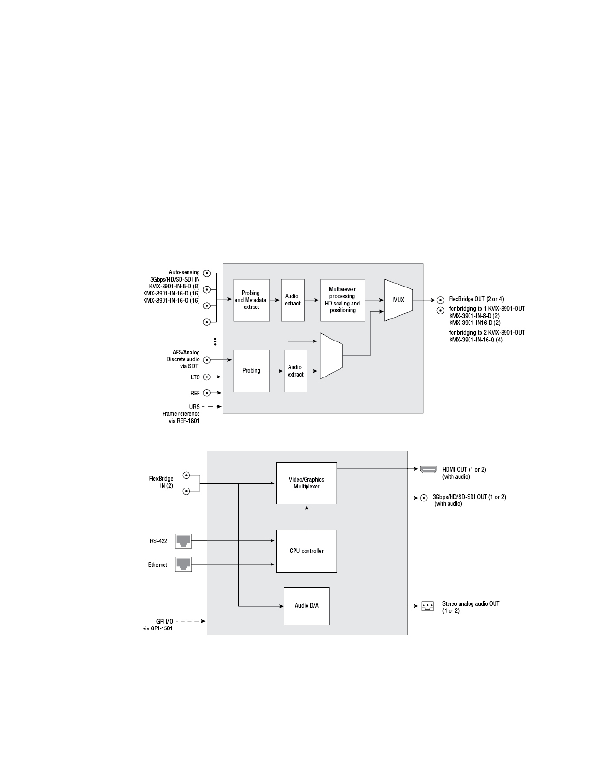
Functional block diagrams
Kaleido-Modular-X functional block diagram: KMX-3901-IN input module
Kaleido-Modular-X functional block diagram: KMX-3901-OUT output module
2
Page 7

Getting Organized
This section provides information about system requirements, and items shipped with your
Kaleido-Modular-X.
Required Materials
Your Kaleido-Modular-X system package includes the following:
• 1–4 KMX-3901-IN input cards with matching rear modules, as per order
Input module parts Description
KMX-3901-IN-8-D 8 input HD/SD-SDI and 3 Gbps input module with dual
KMX-3901-IN-8-D-3TRP Triple rear connector panel with bypass relay.
KMX-3901-IN-16-D 16 input HD/SD-SDI and 3 Gbps input module with dual
KMX-3901-IN-16-D-3QRP Quadruple rear connector panel with bypass relay.
KMX-3901-IN-16-Q 16 input HD/SD-SDI and 3 Gbps input module with quad
KMX-3901-IN-16-Q-3PRP Quintuple rear connector panel with bypass relay.
Kaleido-Modular-X
Quick Start Guide
FlexBridge outputs.
FlexBridge outputs.
FlexBridge outputs. convertible to a 4K UHD prescaler.
• 1–4 KMX-3901-IN-M3 rear modules, M3 cables, and NVISION router-side rears, as per
order
M3 module parts Description
KMX-3901-IN-M3-D-3PRP Quadruple rear connector panel with bypass relay for the M3
cable. Use with KMX-3901-IN-16-D.
KMX-3901-IN-M3-Q-3PRP Quintuple rear connector panel with bypass relay for the M3
cable. Use with KMX-3901-IN-16-Q.
• 1 or 2 KMX-3901-OUT output cards, with rear modules, as per order
Output module parts Description
KMX-3901-OUT-S Single head output module, upgradable to dual head outputs.
KMX-3901-OUT-D Dual head output module.
KMX-3901-OUT-D-3DRP Double rear connector panel.
KMX-3901-OUT-D-3+SRP Single rear connector panel. Compatible with Densité 3+ FR1
only.
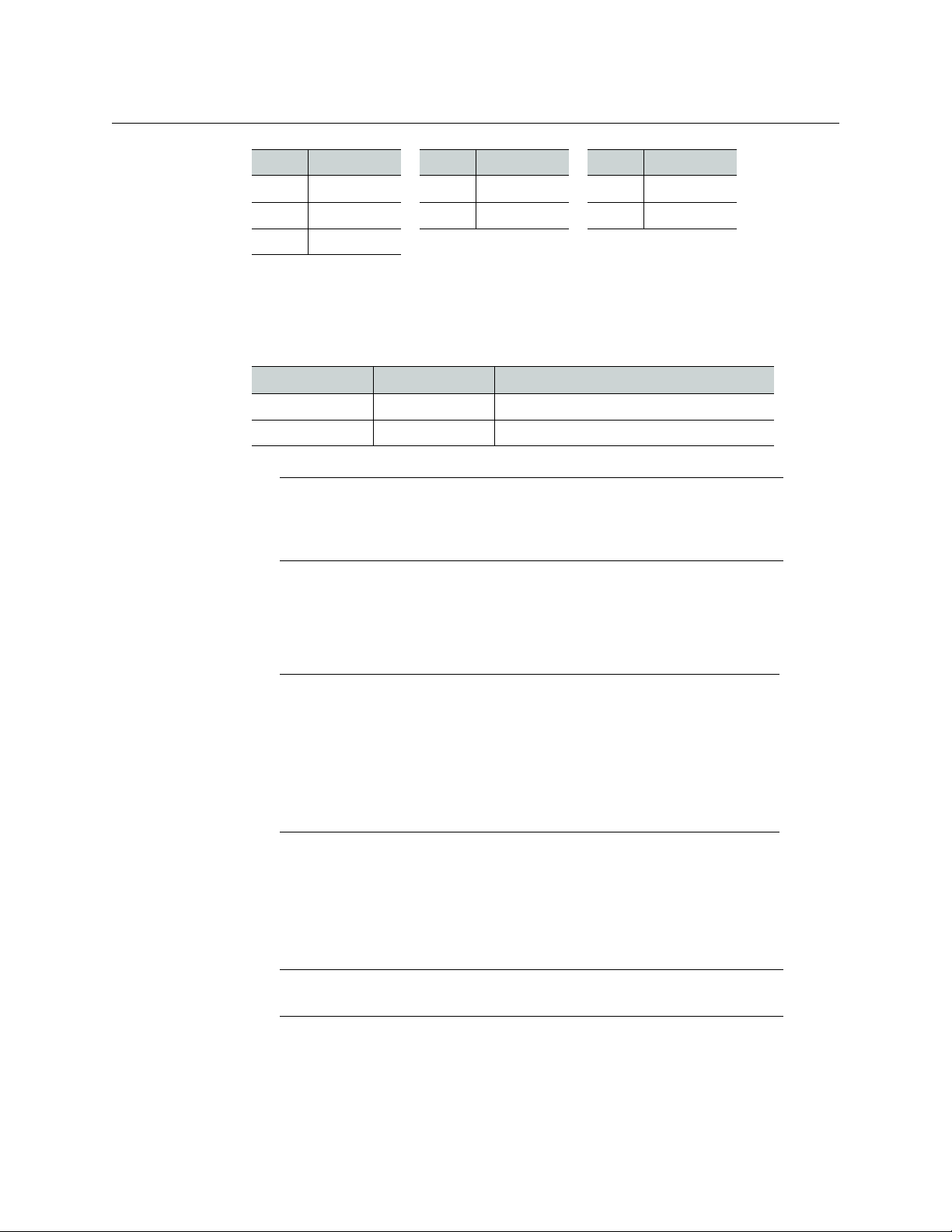
• 1–16 12-inch FlexBridge cables (DIN-DIN coax cables), as per order
Model FlexBridge Model FlexBridge Model FlexBridge
8 × 1 1 24 × 1 2 48 × 2 6
8 × 2 2 24 × 2 4 48 × 4 12
3
Page 8
Setting Up Your Kaleido-Modular-X System
Getting Organized
Model FlexBridge Model FlexBridge Model FlexBridge
16 × 1 1 32 × 2 4 64 × 2 8
16 × 2 2 32 × 4 8 64 × 4 16
16 × 4 4
• 2 WECO analog audio mating connectors for each output card
• 2 serial port adapters (1 with straight cabling and 1 with crossover cabling — see RS-
422 Connection Diagram, on page 47) for every output card ordered with a double rear
connector panel
Part number Adapter cabling RS-422 pinout at the DE-9P connector
1737-3000-102 Straight Controller (SMPTE master) mode
1792-3700-100 Crossover Tributary (SMPTE slave) mode
Note: The single rear connector panel KMX-3901-OUT-D-3+SRP does not
have a serial port. To support a serial device, your Kaleido-Modular-X system
must have at least one output card with a double rear connector panel
(KMX-3901-OUT-D-3DRP).
• The Kaleido-Modular-X Quick Start Guide (this document)
• DVD including the Release Notes for the current version of the Kaleido-X software, the
Kaleido-X User’s Manual, database samples, Quick Start guides and hardware reference
manuals for all multiviewer models
Note: In line with our commitment to environmental preservation, only the
Quick Start Guide for your multiviewer model, and some ancillary
documents (e.g. welcome letters, warranty cards) are distributed in printed
form. All manuals and the Release Notes are available on the DVD that
shipped with your multiviewer. See the Documentation section of the
Release Notes for a complete list. You can obtain the latest version of the
manuals, the Release Notes, as well as software and useful data, from the
Software and documentation section of Grass Valley’s support portal.
In addition to the above, you might need the following (not supplied):
• At least one Densité 3 housing frame
• For a quad-head system with 64 inputs, or if you wish to have separate input and
output stages, then you will also need a separate Densité 3 or Densité
3+ FR1 frame to
house your output cards
Note: Output cards with a single rear connector panel (KMX-3901-OUT-D-
) are compatible with Densité 3+ FR1 only.
3+SRP
• A Densité CPU-ETH2 controller card for each housing frame
(Optionally: a GPI-1501 GPI I/O module, a REF-1801 HD/SD frame reference module)
•Up to 4 displays
4
Page 9
Kaleido-Modular-X
Quick Start Guide
• A dedicated 100Base-T Ethernet switch with enough ports for the KMX-3901-OUT
output cards, the housing frames’ Densité CPU-ETH2 controller cards, client PCs,
Kaleido-RCP2 units, and Audio Bridge Terminals
• Client PC (see below for system requirements)
• Cables (to connect your multiviewer to video sources, to displays, and to the network):
Cable type Purpose
CAT-5 For Ethernet connectivity
Display cables To connect the multiviewer’s HDMI outputs to displays:
•Standard HDMI cables
• Extension modules—for example, Grass Valley’s DXF-200
DVI/HDMI Optical Extension System:
• part number DXF-200-B, for output cards with a double
rear connector panel (KMX-3901-OUT-D-3DRP)
• part number DXF-200-C, for output cards with a single
rear connector panel (KMX-3901-OUT-D-3+SRP)
To connect the multiviewer’s SDI outputs to displays:
• Standard coaxial cables with DIN 1.0/2.3 connectors
• SDI to HDMI 2.0 (or SDI to DisplayPort) converter—for
example, AJA’s Hi5-4K Mini-Converter (firmware version
2.2 or later)
Video cables Standard coaxial cables with DIN 1.0/2.3 connectors
Note: On all Kaleido multiviewers, the network adapters are set to auto-
negotiate. By default, the connection speed and duplex mode will be set
automatically based on the corresponding port settings on the switch.
System Requirements for a Client PC
A client PC or laptop meeting the following requirements is required to access the XAdmin
Web client, and the other Kaleido-X client applications.
Operating system Windows XP Professional, Windows 7, Windows 8, or Windows 8.1
Processor Core 2 Duo at 2 GHz, or better
Memory At least 2 GB of RAM
Disk space At least 2 GB free
Step 1: Physical Setup
To set up the Kaleido-Modular-X hardware
1 Install your Densité 3 and Densité 3+ FR1 housing frames in their designated rack
position, if they are not installed already (refer to the appropriate manuals for your
frames: the Densité
Installation and Operation, available from the Grass Valley support portal).
3+ FR1 User Manual, or the Densité 3 Housing Frame Guide to
5
Page 10
Setting Up Your Kaleido-Modular-X System
Physical Setup
2 Identify the appropriate slots for your new cards.
The following table shows the number of slots required for every available input and
output cards. In a Densité 3 or Densité
ETH2 controller card. The Densité
1501. In a Densité 3 frame, allow one slot for the GPI-1501 (if available).
Card Description Rear panel
KMX-3901-IN-8-D 8-input HD/SD-SDI and 3 Gbps input module
3+ FR1 frame, there is a special slot for the CPU-
3+ FR1 frame has another special slot for the GPI-
3 slots
with dual FlexBridge outputs
KMX-3901-IN-16-D 16-input HD/SD-SDI and 3 Gbps input module
with dual FlexBridge outputs
KMX-3901-IN-16-Q 16-input HD/SD-SDI and 3 Gbps input module
with quad FlexBridge outputs (convertible to a
4K UHD prescaler)
KMX-3901-OUT-S (with
KMX-3901-OUT-D-3DRP)
KMX-3901-OUT-S (with
KMX-3901-OUT-D-3+SRP)
KMX-3901-OUT-D (with
KMX-3901-OUT-D-3DRP)
KMX-3901-OUT-D (with
KMX-3901-OUT-D-3+SRP)
Single-head output module, with double rear
connector panel
Single-head output module, with single rear
connector panel
Dual-head output module, with double rear
connector panel
Dual-head output module, with single rear
connector panel
4 slots
5 slots
2 slots
1 slot
2 slots
1 slot
The following tables show examples of slot distributions for typical Kaleido-Modular-X
configurations. (In these examples, the output cards have a double rear connector
panel. A Densité
3+ FR1 frame can house up to 4 output cards with single rear panels.)
64 × 4 in two separate housing frames
Card Model Rear panel covers... Insert card at...
Output A KMX-3901-OUT-D Slots 1–2 (e.g., in
Densité
3+ FR1)
Slot 1
Output B KMX-3901-OUT-D Slots 3–4 (e.g., in
Densité
Input A KMX-3901-IN-16-Q Slots 1–5 Slot 3
Input B KMX-3901-IN-16-Q Slots 6–10 Slot 8
Input C KMX-3901-IN-16-Q Slots 11–15 Slot 13
Input D KMX-3901-IN-16-Q Slots 16–20 Slot 18
3+ FR1)
Slot 3
64 × 2
Card Model Rear panel covers... Insert card at...
Output A KMX-3901-OUT-D Slots 1–2 Slot 1
Input A KMX-3901-IN-16-D Slots 3–6 Slot 5
Input B KMX-3901-IN-16-D Slots 7–10 Slot 9
6
Page 11

64 × 2 (continued)
Card Model Rear panel covers... Insert card at...
Input C KMX-3901-IN-16-D Slots 11–14 Slot 13
Input D KMX-3901-IN-16-D Slots 15–18 Slot 17
48 × 4
Card Model Rear panel covers... Insert card at...
Output B KMX-3901-OUT-D Slots 2–3 Slot 2
Output A KMX-3901-OUT-D Slots 4–5 Slot 4
Input A KMX-3901-IN-16-Q Slots 6–10 Slot 8
Input B KMX-3901-IN-16-Q Slots 11–15 Slot 13
Input C KMX-3901-IN-16-Q Slots 16–20 Slot 18
48 × 2
Card Model Rear panel covers... Insert card at...
Kaleido-Modular-X
Quick Start Guide
Output A KMX-3901-OUT-D Slots 1–2 Slot 1
Input A KMX-3901-IN-16-D Slots 3–6 Slot 5
Input B KMX-3901-IN-16-D Slots 7–10 Slot 9
Input C KMX-3901-IN-16-D Slots 11–14 Slot 13
32 × 4
Card Model Rear panel covers... Insert card at...
Output B KMX-3901-OUT-D Slots 2–3 Slot 2
Output A KMX-3901-OUT-D Slots 4–5 Slot 4
Input A KMX-3901-IN-16-Q Slots 6–10 Slot 8
Input B KMX-3901-IN-16-Q Slots 11–15 Slot 13
32 × 2
Card Model Rear panel covers... Insert card at...
Output A KMX-3901-OUT-D Slots 1–2 Slot 1
Input A KMX-3901-IN-16-D Slots 3–6 Slot 5
Input B KMX-3901-IN-16-D Slots 7–10 Slot 9
7
Page 12

Setting Up Your Kaleido-Modular-X System
Physical Setup
24 × 2
Card Model Rear panel covers... Insert card at...
Output A KMX-3901-OUT-D Slots 2–3 Slot 2
Input A KMX-3901-IN-16-D Slots 4–7 Slot 6
Input B KMX-3901-IN-8-D Slots 8–10 Slot 9
16 × 4
Card Model Rear panel covers... Insert card at...
Output B KMX-3901-OUT-D Slots 2–3 Slot 2
Output A KMX-3901-OUT-D Slots 4–5 Slot 4
Input A KMX-3901-IN-16-Q Slots 6–10 Slot 8
16 × 2, 16 × 1
Card Model Rear panel covers... Insert card at...
Output A KMX-3901-OUT-D Slots 1–2 Slot 1
Input A KMX-3901-IN-16-D Slots 3–6 Slot 5
8 × 2, 8 × 1
Card Model Rear panel covers... Insert card at...
Output A KMX-3901-OUT-D Slots 2–3 Slot 2
Input A KMX-3901-IN-8-D Slots 4–6 Slot 5
3 Remove the blank rear panels that cover the slots where you wish to install your cards,
by releasing their captive screws.
4 Position the new rear panels, and secure them in place with the captive screws at the
bottom (or on the right, in the case of a Densité
3+ FR1 frame).
5 Slide each of your new input and output cards into the appropriate slot (refer to the
table matching your intended configuration, above, if needed), and push gently on the
handle to seat the connectors. Seating an input card requires more pressure.
IMPORTANT
• If you need to replace or momentarily remove a rear panel, make sure to
first remove the corresponding card itself from its slot (see Replacing Cards,
in the Kaleido-Modular-X Hardware Description & Installation Manual).
• Removing more than one input card at a time from a Kaleido-Modular-X
system in operation is not supported.
6 Verify that each card is securely seated in its slot, and leave the frame door open so that
you can monitor all the card’s LEDs.
8
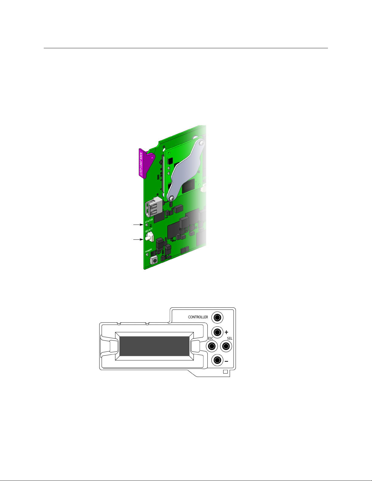
Page 13
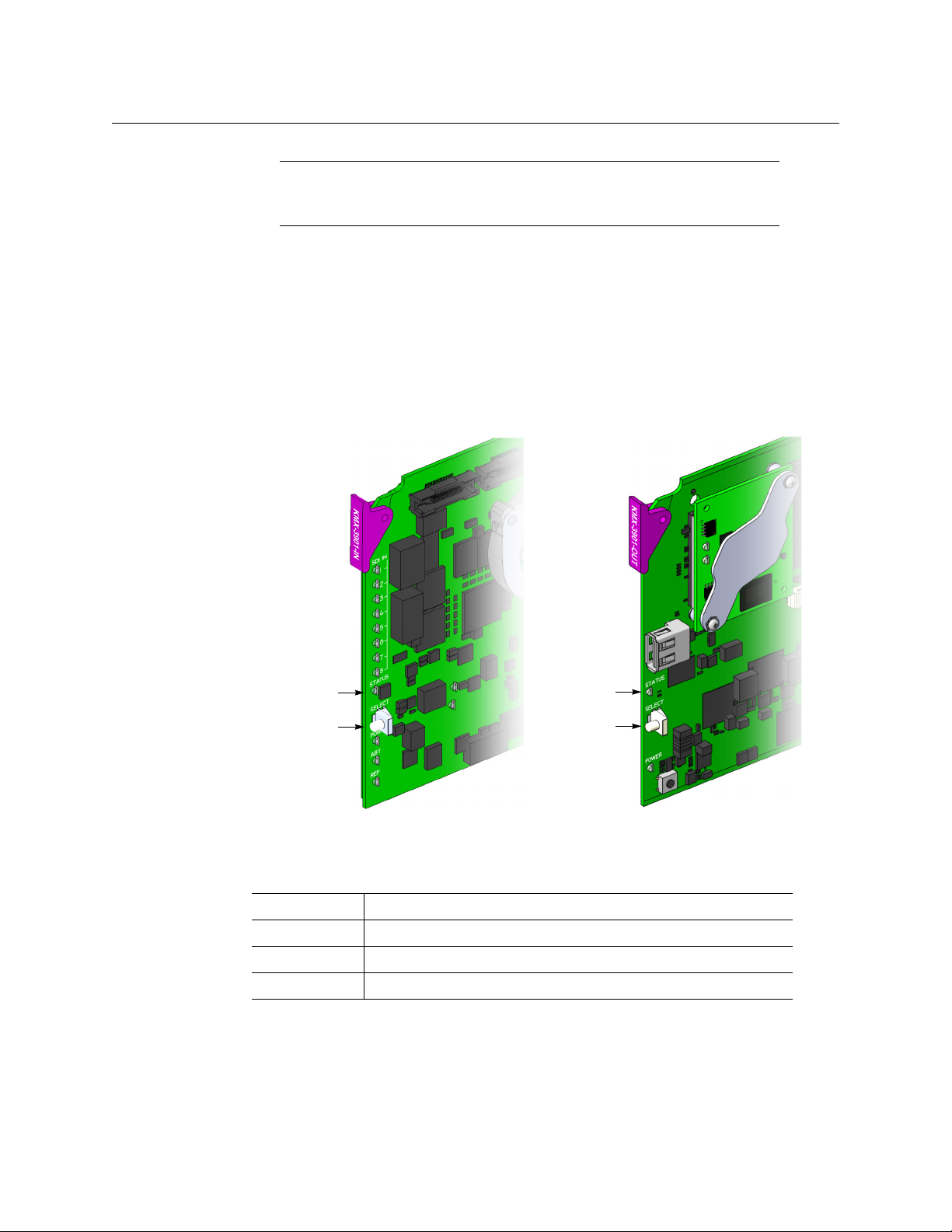
Kaleido-Modular-X
Select button
Status LED
Select button
Status LED
Front edge of a KMX-3901 input card Front edge of a KMX-3901 output card
Quick Start Guide
Note: For more information on the card’s LEDs, refer to the Kaleido-
Modular-X Hardware Description & Installation Manual, available on the DVD
that shipped with your system.
7 Make the physical connections between your input and output cards, by using the
FlexBridge cables that shipped with your system. See
Bridging the Input and Output
Cards in a Kaleido-Modular-X, on page 13.
8 Power up the frame, if it was not in operation already.
Once the networking parameters are correctly configured on your Kaleido-Modular-X
output cards, it will not be necessary to switch off the housing frame’s power when
installing or removing cards.
The Kaleido-Modular-X system starts up. The startup sequence takes approximately
four minutes, during which time every card’s status LED is blinking orange.
Once the startup has completed, the status LEDs on the output cards should be red
(steady) because the cards are not connected to the network yet:
Green Normal
Blinking orange Booting (or the card is selected for local control)
Red Firmware initialization in progress / no Ethernet / SD card error
Blinking red Fan failure / no rear / duplicate IP address
9 If your system includes KMX-3901-IN-16-Q input cards to be used as 4K UHD prescalers,
connect their FlexBridge outputs A1 and B1 to the 3G/HD SDI inputs you wish to use
for your 4K monitoring purposes, at the rear of a KMX-3901 input card, and then see
Converting a KMX-3901-IN-16-Q Input Card to a 4K UHD Prescaler, on page 20, to
enable these cards’ prescaler mode.
9
Page 14

Setting Up Your Kaleido-Modular-X System
Physical Setup
Example: 4K UHD prescaler’s FlexBridge outputs A1 and B1, connected to
3G/HD SDI inputs 5 and 6, at the rear of a KMX-3901-IN-16-D input card
10 Connect the Kaleido-RCP2 and the Audio Bridge Terminal (if available) to a dedicated
100Base-T Ethernet switch. You can also connect a mouse and a keyboard to your
Kaleido-RCP2.
Notes
• The Kaleido-RCP2, and Audio Bridge Terminal (ABT) are optional devices,
and may not have been shipped with your Kaleido-Modular-X system. For
information on these and other Kaleido -Modular-X options, please contact
your Grass Valley sales representative.
• You may need to upgrade your Audio Bridge Terminal and Kaleido-RCP2
devices (if available) to the latest firmware. The update files can be found
on the DVD that shipped with your multiviewer, and on Grass Valley’s
support portal. Please refer to the Kaleido-RCP2 Guide to Installation and
Operation, and to the Audio Bridge Terminal Guide to Installation and
Operation (available on the DVD, and from the portal) for instructions on
how to determine the firmware level, and how to perform the upgrade for
these devices.
• The Kaleido-Modular-X supports one ABT device. With a 3RU model, you
can achieve redundancy by connecting the ABT to more than one input
card, in which case the Kaleido-Modular-X system uses the signal from the
input card that is the farthest from the output cards (i.e., Input
have 4 input cards, Input
input cards).
C if you have 3 input cards, Input B if you have 2
D, if you
10
Kaleido-Modular-X output cards automatically detects the resolution of any connected
display. If the required information is not available, then a fall-back resolution of
× 1080 @ 60 Hz (HDTV) is used.
1920
Page 15
Kaleido-Modular-X
Quick Start Guide
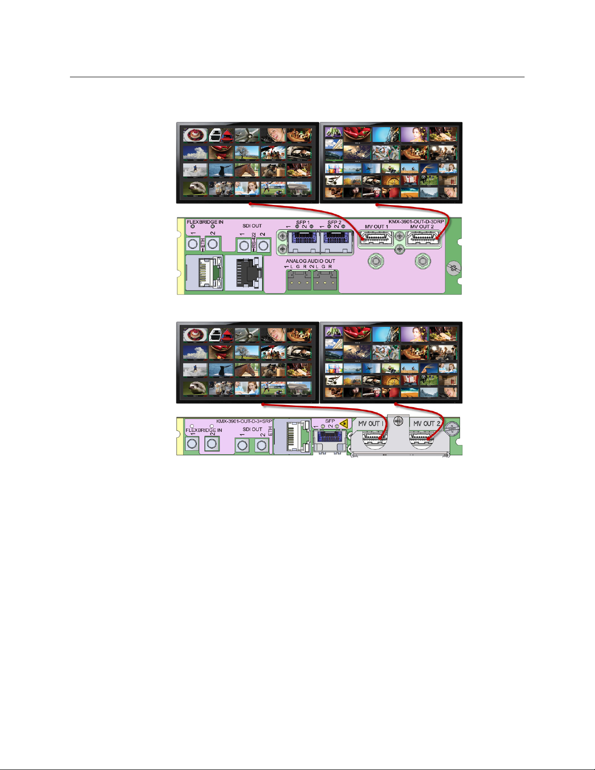
11 Connect your Kaleido-Modular-X output cards to displays that support this resolution.
• Monitor wall displays: Connect the output cards’ MV OUT outputs to the displays.
HDMI outputs on double rear module, connected to displays
HDMI outputs on single rear module, connected to displays
• Quad-link 4K UHD output:
• Four 1080p displays—In the case of a quad-head system meant to output a 4K
UHD signal to four 1080p displays, connect the output cards’ SDI monitoring
outputs to the displays, referring to the table below for proper mapping.
• One 4K UHD display—If your system is meant to output to a single 4K UHD
display, connect the output cards’ SDI monitoring outputs to the display, using
an SDI-to-HDMI converter, if needed. Refer to the table below for proper
mapping.
The SDI outputs are mapped as follows. This configuration does not support
rotated displays. Refer to Creating a 4K UHD Room, and to 4K UHD Spanning, in the
11
Page 16
Setting Up Your Kaleido-Modular-X System
Physical Setup
Kaleido-X User’s Manual, for instructions on how to create 4K UHD rooms and
layouts.
OUTPUT A,
SDI OUT 1
OUTPUT A,
SDI OUT 2
Top l e f t
quadrant
Bottom left
quadrant
OUTPUT B,
SDI OUT 1
OUTPUT B,
SDI OUT 2
Top r i ght
quadrant
Bottom right
quadrant
• Broadcast monitors: If your installation involves broadcast monitors, connect
them to the appropriate SDI outputs. It is also possible to connect SDI outputs to a
router. Refer to Configuring the HD-SDI Monitoring Output Format, in the Kaleido-X
User’s Manual, for instructions on setting the scan format.
If you wish to use a different resolution, see Changing the Output Resolution, on
page 19, for detailed instructions.
IMPORTANT
Within a Kaleido-Modular-X system, all output heads must be configured
with the same refresh rate. If your system is referenced, then the heads’
refresh rate must also match the reference signal's refresh rate.
12 Connect one or more video sources to the Kaleido-Modular-X input cards.
13 If you have configured 4K UHD prescaler cards (at step 9, above), connect one or two
quad link 3G-SDI signal sources to each prescaler card, as follows:
Description Connector
Link 1A – Top left quadrant of 4K UHD signal A 3G/HD/SD IN 1
Link 2A – Top right quadrant of 4K UHD signal A 3G/HD/SD IN 2
Link 3A – Bottom left quadrant of 4K UHD signal A 3G/HD/SD IN 9
12
Link 4A – Bottom right quadrant of 4K UHD signal A 3G/HD/SD IN 10
Link 1B – Top left quadrant of 4K UHD signal B 3G/HD/SD IN 5
Link 2B – Top right quadrant of 4K UHD signal B 3G/HD/SD IN 6
Link 3B – Bottom left quadrant of 4K UHD signal B 3G/HD/SD IN 13
Link 4B – Bottom right quadrant of 4K UHD signal B 3G/HD/SD IN 14
IMPORTANT
The 4K UHD prescaler card and its 4K UHD source signals must be
referenced together.
14 If your system configuration involves M3 cables, connect them between the
appropriate output modules on the router side, and the KMX-3901-IN-M3 rear modules
on the multiviewer side.
Page 17

Kaleido-Modular-X
KMX-3901-IN-M3-D-3QRP
rear module
KMX-3901-IN-M3-Q-3PRP rear module
Quick Start Guide
Note: When the M3 output card is installed in the lower output bays of an
NV8576 router frame, its backplane is upside down and the ordering of its
ports differs from when the backplane is installed in the upper bays (right
side up) of an NV8576 frame. Refer to NV8500 M3 Backplane Connections, in
the Kaleido-Modular-X Hardware Description & Installation Manual to
determine the correct mapping between router outputs and multiviewer
inputs, when using the M3 cable.
15 Connect a reference source (if available) to one or more reference inputs.
Note: Unless your system includes a 4K UHD prescaler card (see step 9, and
step 13 above), a reference is optional. If minimal processing delay is
required for your monitoring purposes, then you must reference your
system. However, if you must monitor 50
(or vice-versa), then do not reference your system.
To properly reference a Kaleido-Modular-X system, either:
• Connect all reference inputs on all the KMX-3901-IN input cards, or
• Use a REF-1801 card externally connected to the house reference, in every
Densité frame that contains KMX-3901-IN input cards. The REF-1801 will
distribute the reference to all cards in the frame internally through the URS
on the frame mid-plane.
Hz input signals on 60 Hz displays
You can now proceed with the networking setup (see Step 2: Networking Setup, on
page 21).
Bridging the Input and Output Cards in a Kaleido-Modular-X
The Kaleido-Modular-X requires FlexBridge connections between the input and output
cards. Use the DIN-DIN coax cables that shipped with your system to make these physical
connections. The number of cables required depends on the number of input and output
cards (see
Required Materials, on page 3).
13
Page 18

Setting Up Your Kaleido-Modular-X System
INPUT A OUTPUT A
Rear panels for a KMX-3901-IN-8-D (left), and
KMX-3901-OUT-D (double panel shown on
right). The Flexbridge connectors are the
same on the KMX-3901-IN-8-D and
KMX-3901-IN-16-D card’s rear panels, and on
the output card’s single and double rear
panels.
Physical Setup
FlexBridge wiring for a 8 × 1 or 16 × 1 system
To connect the input and output cards in a Kaleido-Modular-X 8 × 1 or 16 × 1
•Bridge Input A to Output A, by connecting:
• INPUT A FLEXBRIDGE OUT A1 to OUTPUT A FLEXBRIDGE IN 1
FlexBridge wiring for a 8 × 2 or 16 × 2 system
To connect the input and output cards in a Kaleido-Modular-X 8 × 2 or 16 × 2
•Bridge Input A to Output A, by connecting:
• INPUT A FLEXBRIDGE OUT A1 to OUTPUT A FLEXBRIDGE IN 1
• INPUT A FLEXBRIDGE OUT A2 to OUTPUT A FLEXBRIDGE IN 2
14
Page 19

Kaleido-Modular-X
Rear panels for a KMX-3901-IN-8-D (left), and
KMX-3901-OUT-D (double panel shown on
right). The Flexbridge connectors are the
same on the KMX-3901-IN-8-D and
KMX-3901-IN-16-D card’s rear panels, and on
the output card’s single and double rear
panels.
INPUT A OUTPUT A
INPUT B INPUT A OUTPUT A
Quick Start Guide
FlexBridge wiring for a 32 × 2 system
To connect the input and output cards in a Kaleido-Modular-X 32 × 2
1 Complete the bridging for a 16 × 2 configuration (see FlexBridge wiring for a 8 × 2 or 16
× 2 system, above).
2Bridge Input B to Input A, by connecting:
• INPUT B FLEXBRIDGE OUT A1 to INPUT A FLEXBRIDGE IN A1
• INPUT B FLEXBRIDGE OUT A2 to INPUT A FLEXBRIDGE IN A2
15
Page 20

Setting Up Your Kaleido-Modular-X System
INPUT A
OUTPUT A
Physical Setup
FlexBridge wiring for a 48 × 2 system
To connect the input and output cards in a Kaleido-Modular-X 48 × 2
1 Complete the bridging for a 32 × 2 configuration (see FlexBridge wiring for a 32 × 2
system, above).
2Bridge Input C to Input B, by connecting:
• INPUT C FLEXBRIDGE OUT A1 to INPUT B FLEXBRIDGE IN A1
• INPUT C FLEXBRIDGE OUT A2 to INPUT B FLEXBRIDGE IN A2
FlexBridge wiring for a 64 × 2 system
To connect the input and output cards in a Kaleido-Modular-X 64 × 2
1 Complete the bridging for a 48 × 2 configuration (see FlexBridge wiring for a 48 × 2
system, above).
2Bridge Input D to Input C, by connecting:
• INPUT D FLEXBRIDGE OUT A1 to INPUT C FLEXBRIDGE IN A1
• INPUT D FLEXBRIDGE OUT A2 to INPUT C FLEXBRIDGE IN A2
FlexBridge wiring for a 16 × 4 system
To connect the input and output cards in a Kaleido-Modular-X 16 × 4
1Bridge Input A to Output A, by connecting:
• INPUT A FLEXBRIDGE OUT A1 to OUTPUT A FLEXBRIDGE IN 1
• INPUT A FLEXBRIDGE OUT A2 to OUTPUT A FLEXBRIDGE IN 2
16
2Bridge Input A to Output B, by connecting:
• INPUT A FLEXBRIDGE OUT B1 to OUTPUT B FLEXBRIDGE IN 1
• INPUT A FLEXBRIDGE OUT B2 to OUTPUT B FLEXBRIDGE IN 2
Page 21

Kaleido-Modular-X
INPUT A
OUTPUT A OUTPUT B
Quick Start Guide
FlexBridge wiring for a 32 × 4 system
To connect the input and output cards in a Kaleido-Modular-X 32 × 4
1 Complete the bridging for a 16 × 4 configuration (see FlexBridge wiring for a 16 × 4
system, above).
2Bridge Input B to Input A, by connecting:
• INPUT B FLEXBRIDGE OUT A1 to INPUT A FLEXBRIDGE IN A1
• INPUT B FLEXBRIDGE OUT A2 to INPUT A FLEXBRIDGE IN A2
• INPUT B FLEXBRIDGE OUT B1 to INPUT A FLEXBRIDGE IN B1
• INPUT B FLEXBRIDGE OUT B2 to INPUT A FLEXBRIDGE IN B2
17
Page 22

Setting Up Your Kaleido-Modular-X System
INPUT B
INPUT A
OUTPUT A OUTPUT B
Physical Setup
FlexBridge wiring for a 48 × 4 system
To connect the input and output cards in a Kaleido-Modular-X 48 × 4
1 Complete the bridging for a 32 × 4 configuration (see FlexBridge wiring for a 32 × 4
system, above).
2Bridge Input C to Input B, by connecting:
• INPUT C FLEXBRIDGE OUT A1 to INPUT B FLEXBRIDGE IN A1
• INPUT C FLEXBRIDGE OUT A2 to INPUT B FLEXBRIDGE IN A2
• INPUT C FLEXBRIDGE OUT B1 to INPUT B FLEXBRIDGE IN B1
• INPUT C FLEXBRIDGE OUT B2 to INPUT B FLEXBRIDGE IN B2
FlexBridge wiring for a 64 × 4 system
To connect the input and output cards in a Kaleido-Modular-X 64 × 4
1 Complete the bridging for a 48 × 4 configuration (see FlexBridge wiring for a 32 × 4
system, above).
2Bridge Input D to Input C, by connecting:
• INPUT D FLEXBRIDGE OUT A1 to INPUT C FLEXBRIDGE IN A1
• INPUT D FLEXBRIDGE OUT A2 to INPUT C FLEXBRIDGE IN A2
• INPUT D FLEXBRIDGE OUT B1 to INPUT C FLEXBRIDGE IN B1
• INPUT D FLEXBRIDGE OUT B2 to INPUT C FLEXBRIDGE IN B2
18
Page 23

Changing the Output Resolution
Select button
Status LED
IMPORTANT
Within a Kaleido-Modular-X system, all output heads must be configured
with the same refresh rate. If your system is referenced, then the heads’
refresh rate must also match the reference signal's refresh rate. If you must
monitor 50
reference your system.
To change the display resolution from the Densité controller’s local control panel
1 Press the Select button on the front edge of the output card whose heads you wish to
configure.
Hz input signals on 60 Hz displays (or vice-versa), then do not
Kaleido-Modular-X
Quick Start Guide
The Status LED on the selected card flashes orange, and the associated control menu
appears on the LCD display of the Densité frame’s local control panel.
2 On the local control panel, press the [–] button twice, until RESOLUTION appears on the
LCD display.
3 Press the SEL button.
HEAD 1 appears on the LCD display.
19
Page 24

Setting Up Your Kaleido-Modular-X System
Physical Setup
4 Press the SEL button again.
5 The current resolution for the monitor wall display that is connected to the
multiviewer’s output head 1 (i.e. through the MV OUT 1 connector) appears on the LCD
display.
6 Press the [+] and [–] buttons, to navigate to a suitable output resolution for your
monitor wall display.
7 Press SEL to apply the value shown on the LCD display.
The selected resolution is applied to the multiviewer’s output head 1.
8 Press ESC to return to the previous level in the local control menu.
HEAD 1 appears again on the LCD display.
9 If you wish to change the resolution on the second output head (if available), then
press the [–] button.
HEAD 2 appears on the LCD display and you can repeat step 4 to step 8 above to verify
or configure the resolution of the display that is connected to the multiviewer’s output
head 2 (i.e. through the MV OUT 2 connector).
10 When you are satisfied with the selected output resolution settings, press the Select
button on the front edge of the output card to exit the control menu.
Notes
• If you do not press any button on the local control panel, the Densité CPUETH2 controller will revert to its normal standby mode, and the selected
card's status LED will revert to its normal operating mode, after 30 seconds.
• If you changed a parameter from the card’s control menu, but have not
applied your change (you did not press the SEL button on the local control
panel), once the 30-second timeout has occurred, the parameters will be
confirmed as if you had pressed the SEL button.
Converting a KMX-3901-IN-16-Q Input Card to a 4K UHD Prescaler
To configure a KMX-3901-IN-16-Q input card as a 4K UHD prescaler
1 Press the Select button on the front edge of the KMX-3901-IN-16-Q input card you wish
to configure.
20
Page 25

Kaleido-Modular-X
Select button
Status LED
Quick Start Guide
The Status LED on the selected card flashes orange, and the associated control menu
appears on the LCD display of the Densité frame’s local control panel.
2 On the local control panel, press the [–] button.
CONFIG appears on the LCD display.
3 Press the SEL button.
4K UHD PRESCALER appears on the LCD display.
4 Press the SEL button.
5 Press the [+] or [–] buttons, if needed, until ENABLE appears on the LCD display.
6 Press the SEL button.
ENABLE appears on the top line of the LCD display, and then, after 10 seconds, a
message appears on the second line to let you know that the card will restart in 20
seconds.
7 After the card has restarted, notice that the SDI LEDs 3, 4, 7, 8, 11, 12, 15, and 16 are not
lit.
This indicates that the card is now configured as a 4K UHD prescaler.
Step 2: Networking Setup
For the Kaleido-Modular-X multiviewer to join a TCP/IP network, it must be configured with
a system name, appropriate IP
also need to configure the Densité CPU-ETH2 networking parameters (if your housing
frames were not already in operation), any new Kaleido-RCP2 and Audio Bridge Terminal
units you ordered, and a client
devices (see
Configuring a Client PC, on page 36).
addresses, network mask, and gateway settings. You may
PC to communicate with the multiviewer and its peripheral
A quad-head Kaleido-Modular-X multiviewer system requires three IP addresses (one for
each output card, one for the system), while a dual- or single-head requires only one (the
21
Page 26
Setting Up Your Kaleido-Modular-X System
Networking Setup
output card’s IP address doubles as the system IP address). Kaleido-Modular-X output cards
are shipped with the following default settings:
KMX-3901-OUT default IP settings
System IP address 192.168.3.31
Network mask 255.255.255.0
Gateway 0.0.0.0
Output A IP address 192.168.3.31
Output B IP address 0.0.0.0
Densité 3 and Densité 3+ FR1 housing frames are shipped with their CPU-ETH2 controller
configured with the following default settings:
Densité CPU-ETH2 controller default IP settings
£
IP address 1 192.168.3.1
Network mask 255.255.255.0
Gateway 0.0.0.0
IP address 2 0.0.0.0
Network mask 0.0.0.0
Gateway 0.0.0.0
Once the networking parameters are correctly configured on your Kaleido-Modular-X
output cards, it will not be necessary to switch off the housing frame’s power when
installing or removing cards.
To set the system name and IP addresses for your Kaleido-Modular-X multiviewer
1 If any frame housing your Kaleido-Modular-X input and output cards was not already in
operation, configure its Densité CPU-ETH2 controller’s networking parameters.
See
Setting a Densité CPU-ETH2 Controller’s IP Address on page 23.
2 For every frame housing Kaleido-Modular-X input or output cards, verify that the
Densité CPU-ETH2 controller’s automatic restore feature is enabled (see
Enabling the
CPU-ETH2 Automatic Restore Feature, on page 24).
Note: For the card hot swap feature to function properly, the CPU-ETH2
automatic restore feature must be activated on all frames housing
Kaleido-Modular-X cards (i.e., both input and output cards).
3 Configure your output cards’ networking parameters:
• If you are setting up a quad-head Kaleido-Modular-X, replace the system
address, network mask, default gateway, and both output cards’ IP addresses as
IP
appropriate.
See Configuring the Network Settings for a Quad-Head System on
page 27.
The system IP address will be your system’s virtual IP address. This is the address
you will use to access your system from XEdit and XAdmin, for example.
22
Page 27

Kaleido-Modular-X
Quick Start Guide
• If you are setting up a single-head or a dual-head Kaleido-Modular-X, then replace
address for Output A with an appropriate IP address, and change the
the IP
network mask and default gateway as appropriate.
See Configuring the Network
Settings for a Single- or Dual-Head System on page 25.
The output card’s IP address will automatically become your system’s virtual
address.
IP
4 Configure the Kaleido-RCP2, and Audio Bridge Terminal units you have connected to
your system, if any.
See Using the Kaleido-RCP2 with Default Settings on page 33, and
Configuring an Audio Bridge Terminal, on page 34.
5 Complete your Kaleido-Modular-X system configuration by changing the system name,
if desired.
See Setting the System Name on page 30.
Note: If there are more than one multiviewer in the same network
environment, it is important to assign each a unique system name, so that
you can tell them apart (for example, when using a remote control panel
such as the Kaleido-RCP2 or RCP-200).
You are now ready to open XAdmin and XEdit, from a client PC or laptop within the
same subnet, and verify your system communication status (see
Step 3: XEdit
Installation, on page 38, and Step 4: System Verification, on page 41).
Setting a Densité CPU-ETH2 Controller’s IP Address
To set the Densité controller’s IP address
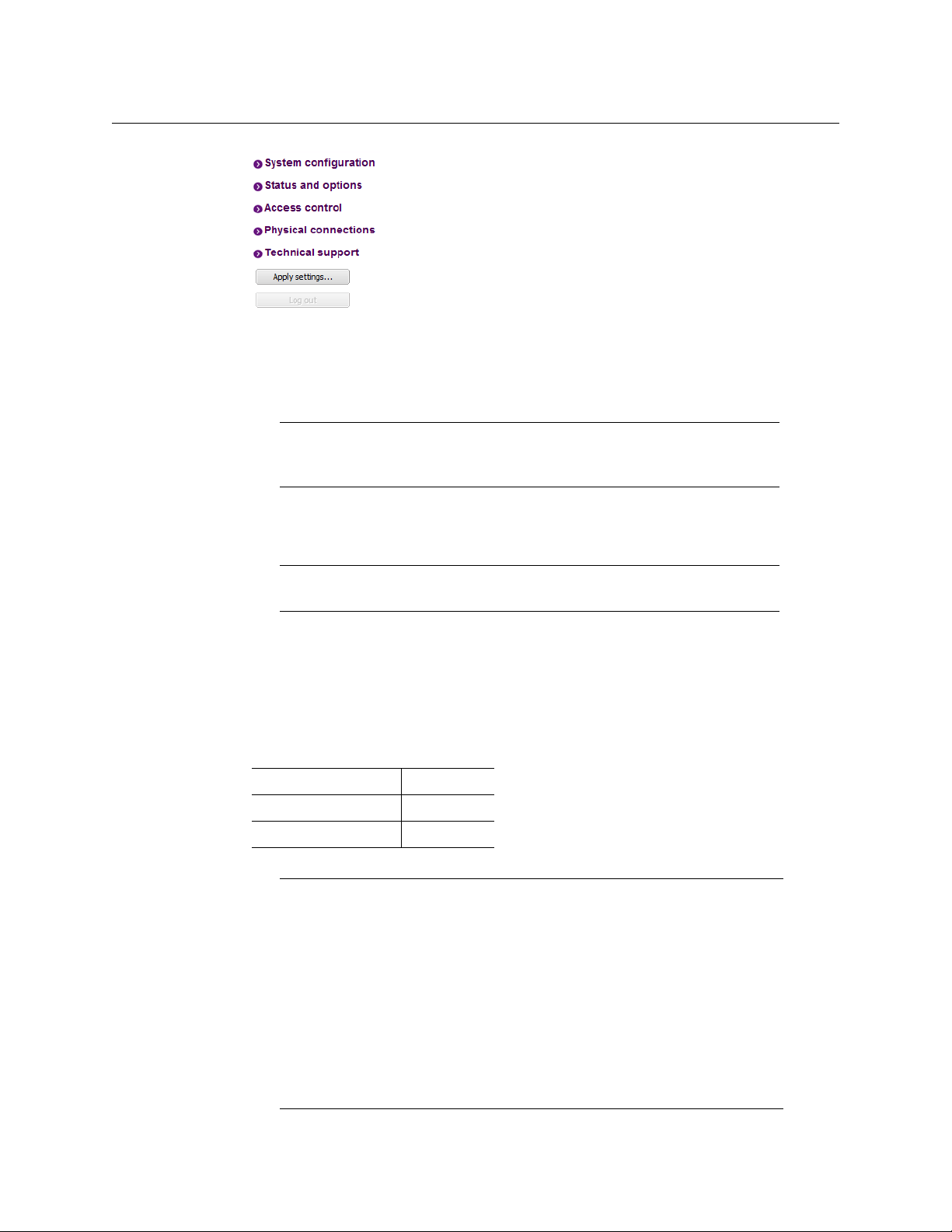
1 On the housing frame’s local control panel, press the CONTROLLER button.
2 Press the [–] button repeatedly until ETH1 OPTIONS appears on the display, and then
press the SEL button.
3 Press the [–] button repeatedly until IP ADDRESS appears on the display.
4 Press the SEL button.
The current value appears on the display.
• Press the [+] and [–] buttons, to change the digit at the current input position.
• Press SEL to move one position to the right.
• Press ESC to move one position to the left.
5 When the display shows the desired value, press SEL repeatedly until you reach the last
position (if needed), and then press SEL once more to save your changes and return to
the previous menu level.
23
Page 28

Setting Up Your Kaleido-Modular-X System
Networking Setup
Note: Pressing ESC when the input focus is in the first position returns to
the previous menu level. Pressing SEL when the input focus is in the last
position saves the changes and returns to the previous menu level.
IP ADDRESS appears on the control panel’s display.
6 Press the [–] button.
NETWORK MASK appears on the control panel’s display.
7Repeat step 4 and step 5 to configure the netmask.
8 Once you have set the network mask, press the [–] button again.
GATEWAY appears on the control panel’s display.
9Repeat step 4 and step 5 to configure the gateway.
10 Once you have set the gateway, press the CONTROLLER button to exit the controller’s
menu.
The Densité controller restarts.
11 Connect the controller card’s ETHERNET 1 port to your Ethernet switch.
Notes
• The Kaleido-Modular-X does not support the controller card’s second
Ethernet port (ETHERNET
• To avoid IP-address conflicts, you should wait until you have configured
the appropriate network settings for your KMX-3901 output cards before
connecting the output cards’ ETH ports to the network.
2).
IMPORTANT
Make sure the controller’s internal clock is set to the correct date and
time.
The clock settings will persist for 10 days after a power loss. Should you later
need to change the time on a CPU-ETH2 controller, then you will have to
restart any multiviewer system housed in the same frame. Refer to the
Densité CPU-ETH2 Enhanced Ethernet Controller Card Guide to Installation
and Operation, for more information.
Enabling the CPU-ETH2 Automatic Restore Feature
To enable the CPU-ETH2 automatic restore feature
1 On the Densité frame’s local control panel, press the CONTROLLER button.
2 Press the [–] button repeatedly until RESTORE POINTS appears on the display, and then
press the SEL button.
3 Press the [–] button repeatedly until DEFAULT ACTION appears on the display, and then
press the SEL button.
• If the control panel’s display shows UPDATE SETTINGS, then the automatic restore
feature is already enabled.
24
Page 29
Kaleido-Modular-X
Select button
Status LED
Quick Start Guide
• If the control panel’s display shows KEEP SETTINGS, navigate to UPDATE SETTINGS
by pressing the [–] button, and then press the SEL button to apply your change.
4 Press the CONTROLLER button to exit the controller’s menu.
Configuring the Network Settings for a Single- or Dual-Head System
To configure the network settings for a Kaleido-Modular-X with one output card
1 Press the Select button on the front edge of the output card.
The Status LED on the selected card flashes orange, and the associated control menu
appears on the display of the Densité frame’s local control panel.
2 On the local control panel, press the [–] button repeatedly until NETWORK SETTINGS
appears on the display, and then press the SEL button.
FRAME IP ADDRESS EDIT appears on the display.
3 Press the [–] button to skip this option (the system will automatically receive the
address you configure for Output A, once the card will have restarted).
IP
NETMASK EDIT appears on the display.
4 Press the SEL button.
The current value appears on the display.
25
Page 30

Setting Up Your Kaleido-Modular-X System
Networking Setup
• Press the [+] and [–] buttons, to change the digit at the current input position.
• Press SEL to move one position to the right.
• Press ESC to move one position to the left.
5 When the display shows the desired value, press SEL repeatedly until you reach the last
position (if needed), and then press SEL once more to save your changes and return to
the previous menu level.
Note: Pressing ESC when the input focus is in the first position returns to
the previous menu level. Pressing SEL when the input focus is in the last
position saves the changes and returns to the previous menu level.
NETMASK EDIT appears on the display.
6 Once you have set the network mask, press the [–] button.
DEFAULT GW EDIT appears on the display.
7Repeat step 4 and step 5 to configure the gateway.
8 Once you have configured the gateway and navigated back to the previous menu level,
press the [–] button again.
LINK MODE EDIT appears on the display.
9 Press the SEL button.
10 The current link mode appears on the display.
Note: On all Kaleido multiviewers, the network adapters are set to auto-
negotiate. By default, the connection speed and duplex mode will be set
automatically based on the corresponding port settings on the switch.
11 If your network's mode of operation requires you to change the link mode, press the [+]
and [–] buttons to navigate to the suitable option (100
Mbps half-duplex, or 100Mbps
full-duplex), and then press SEL to apply the value shown on the display.
The selected link mode is applied.
12 Press ESC to return to the previous level in the local control menu.
LINK MODE EDIT appears again on the display.
13 Press the [–] button.
OUTPUT A IP EDIT appears on the display.
14 Repeat step 4 and step 5 to configure the IP address for Output A.
15 Once you have set the IP address for Output A, press the Select button on the front edge
of the output card to exit the control menu.
Notes
• If you do not press any button on the Densité frame local control panel, the
Densité controller will revert to its normal standby mode, and the selected
card's Status LED will revert to its normal operating mode, after 30
seconds.
26
Page 31

Kaleido-Modular-X
Quick Start Guide
Notes (continued)
• If you changed a parameter from the card’s control menu, but have not
applied your change (you did not press the SEL button on the local control
panel), once the 30-second timeout has occurred, the parameters will be
confirmed as if you had pressed the SEL button.
After a moment, the card restarts. The startup sequence takes approximately four
minutes, during which time the Status LED is first red and then blinking orange. Once
the startup has completed, the Status LED should be red (steady) because the card is
not connected to the network yet.
16 Connect the output card’s ETH port to your Ethernet switch.
17 Check the card’s Status LED again, and make sure that it does not indicate an error
condition.
Green Normal
Blinking orange Booting (or the card is selected for local control)
Red Firmware initialization in progress / no Ethernet / SD card error
Blinking red Fan failure / no rear / duplicate IP address
Should the Status LED indicate an error condition, refer to your Kaleido-Modular-X
Hardware Description & Installation Manual to find out what the other LEDs might be
indicating.
18 Verify that the new IP address is effective, by referring to Verifying an Output Card’s IP
Address and Application Version, on page 46.
Configuring the Network Settings for a Quad-Head System
To configure the network settings for a Kaleido-Modular-X with two output cards
1 Press the Select button on the front edge of one of your system’s output cards.
27
Page 32

Setting Up Your Kaleido-Modular-X System
Select button
Status LED
Networking Setup
The Status LED on the selected card flashes orange, and the associated control menu
appears on the display of the Densité frame’s local control panel.
2 On the local control panel, press the [–] button repeatedly until NETWORK SETTINGS
appears on the display, and then press the SEL button.
FRAME IP ADDRESS EDIT appears on the display.
3 Press the SEL button again.
The current value appears on the display.
• Press the [+] and [–] buttons, to change the digit at the current input position.
• Press SEL to move one position to the right.
• Press ESC to move one position to the left.
4 When the display shows the desired value, press SEL repeatedly until you reach the last
position (if needed), and then press SEL once more to save your changes and return to
the previous menu level.
Note: Pressing ESC when the input focus is in the first position returns to
the previous menu level. Pressing SEL when the input focus is in the last
position saves the changes and returns to the previous menu level.
28
Page 33

Kaleido-Modular-X
Quick Start Guide
FRAME IP ADDRESS EDIT appears on the control panel’s display.
5 Press the [–] button.
NETMASK EDIT appears on the control panel’s display.
6Repeat step 3 and step 4 to configure the netmask.
7 Once you have set the network mask and navigated back to the previous menu level,
press the [–] button again.
DEFAULT GW EDIT appears on the control panel’s display.
8Repeat step 3 and step 4 to configure the gateway.
9 Once you have configured the gateway and navigated back to the previous menu level,
press the [–] button again.
LINK MODE EDIT appears on the control panel’s display.
10 Press the SEL button.
11 The current link mode (“Auto-negotiate”) appears on the LCD display.
Note: On all Kaleido multiviewers, the network adapters are set to auto-
negotiate. By default, the connection speed and duplex mode will be set
automatically based on the corresponding port settings on the switch.
12 If your network's mode of operation requires you to change the link mode, press the [+]
and [–] buttons to navigate to the suitable option (100
Mbps half-duplex, or 100Mbps
full-duplex), and then press SEL to apply the value shown on the display.
The selected link mode is applied.
13 Press ESC to return to the previous level in the local control menu.
LINK MODE EDIT appears again on the LCD display.
14 Press the [–] button.
OUTPUT A IP EDIT appears on the control panel’s display.
15 Repeat step 3 and step 4 to configure the IP address for Output A.
16 Once you have set the IP address for Output A, and navigated back to the previous
menu level, press the [–] button again.
OUTPUT B IP EDIT appears on the control panel’s display.
17 Repeat step 3 and step 4 to configure the IP address for Output B.
18 Once you have set the IP address for Output B, press the Select button on the front edge
of the output card to exit the control menu.
Notes
• If you do not press any button on the Densité frame local control panel, the
Densité controller will revert to its normal standby mode, and the selected
card's Status LED will revert to its normal operating mode, after 30
seconds.
• If you changed a parameter from the card’s control menu, but have not
applied your change (you did not press the SEL button on the local control
panel), once the 30-second timeout has occurred, the parameters will be
confirmed as if you had pressed the SEL button.
29
Page 34

Setting Up Your Kaleido-Modular-X System
Networking Setup
After a moment, the card restarts. The startup sequence takes approximately four
minutes, during which time the Status LED is first red and then blinking orange. Once
the startup has completed, the Status LED should be red (steady) because the card is
not connected to the network yet.
19 Press the Select button on the front edge of the other output card, and repeat from
step 2, to configure the second output card with the same network settings.
20 Connect both output cards’ ETH ports to your Ethernet switch.
21 The system momentarily reports a duplicate IP address on the monitor wall, after which
Output B restarts. Once the startup has completed, check both cards’ Status LEDs
again, and make sure that they do not indicate an error condition.
Green Normal
Blinking orange Booting (or the card is selected for local control)
Red Firmware initialization in progress / no Ethernet / SD card error
Blinking red Fan failure / no rear / duplicate IP address
Should the Status LED indicate an error condition, refer to your Kaleido-Modular-X
Hardware Description & Installation Manual to find out what the other LEDs might be
indicating.
22 Verify that both cards’ and the system’s new IP addresses are effective, by referring to
Verifying the Multiviewer’s IP Addresses and Application Version, on page 45.
Setting the System Name
Once you have configured the output cards from the local control panel, use XAdmin to
complete your system’s network setup.
To set your Kaleido-Modular-X system name
1 Configure your client PC or laptop with an IP address in the same range as the
multiviewer’s current IP
2 Open a Web browser window and enter the multiviewer’s system IP address in the
address bar (see
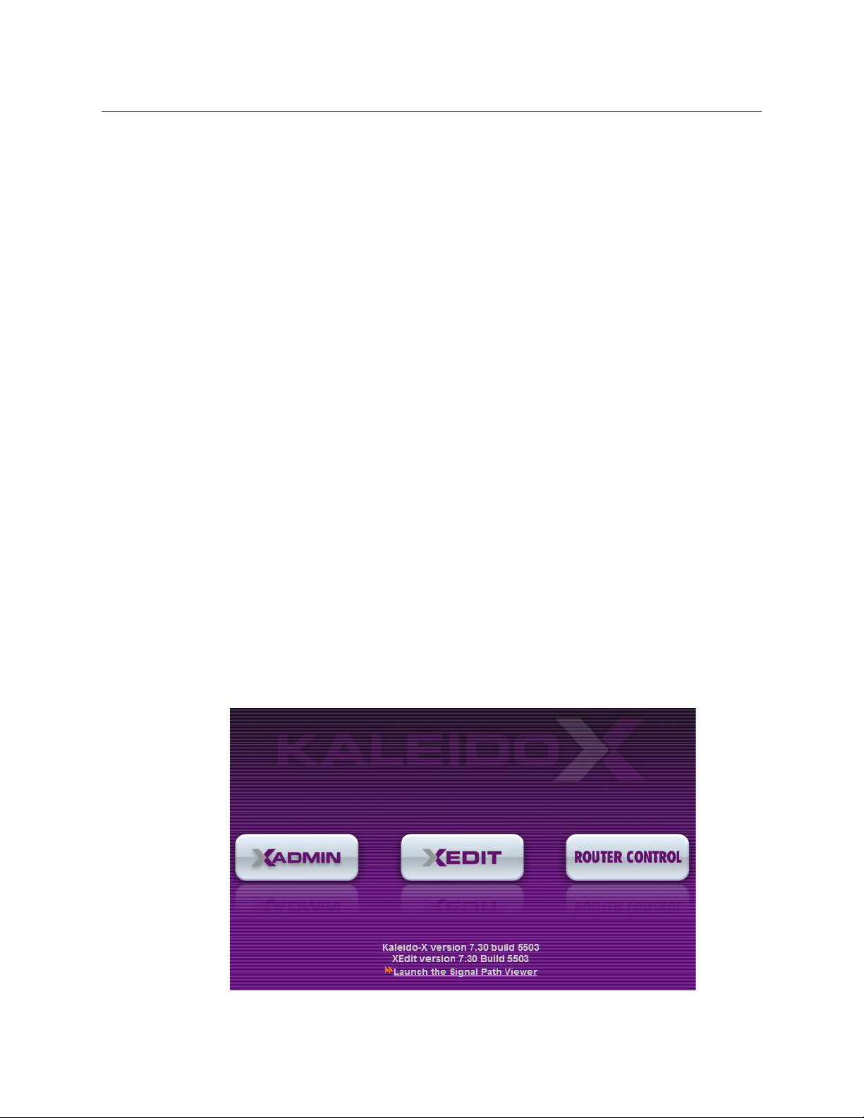
3 The Kaleido-X home page appears.
addresses if needed (see Configuring a Client PC, on page 36).
Finding the System IP Address, on page 45, if needed).
30
Page 35

Kaleido-Modular-X
Quick Start Guide
4 Click the XAdmin button.
5 If you see a security warning, or a certificate error message, then refer to Registering
your Multiviewer's Security Credentials with your Browser, in the Kaleido-X User’s Manual.
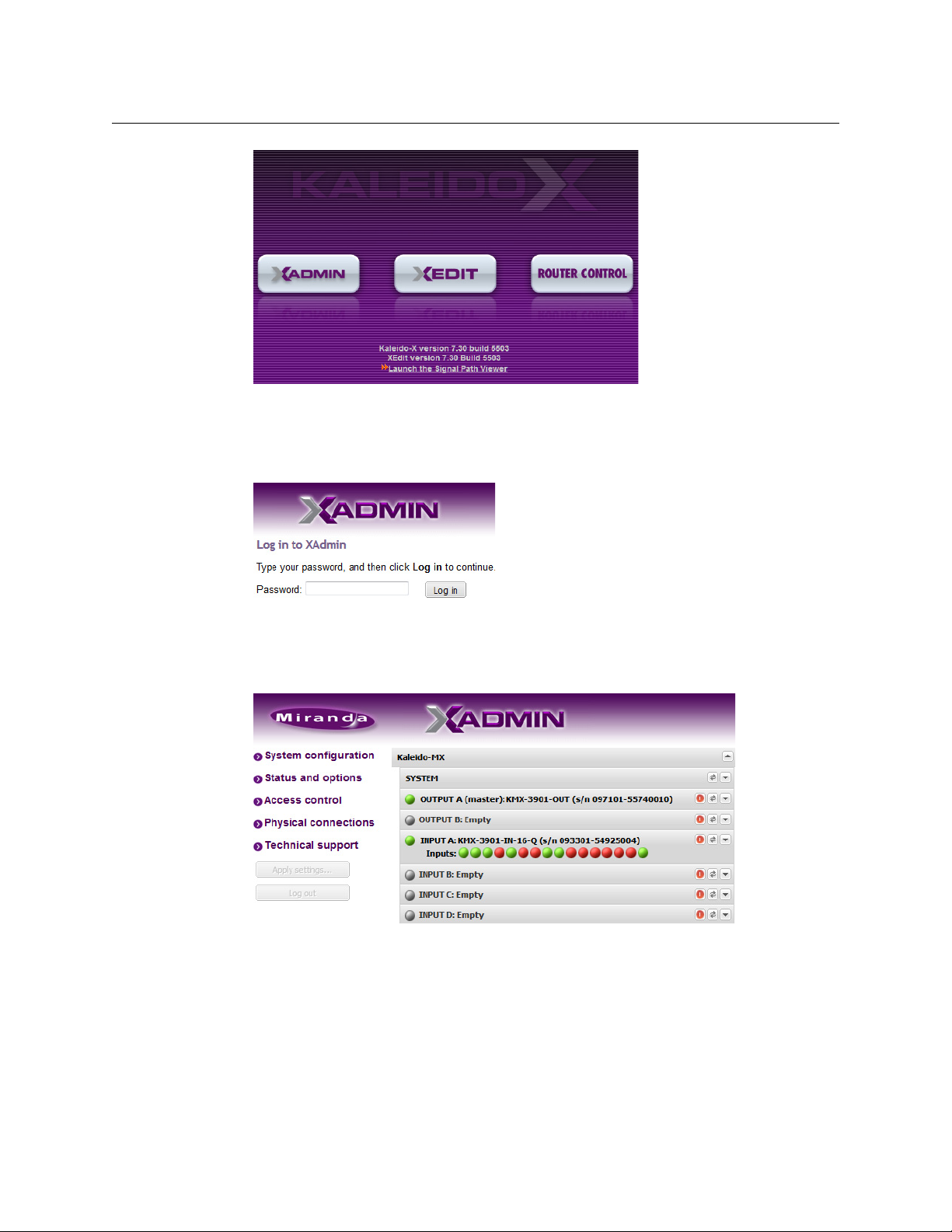
6 If the “Log in to XAdmin” page appears, type the password, and then click Log in.
7 Internet Explorer users: If a blank page appears, then refer to Enabling the
Compatibility View in Internet Explorer 10, in the Kaleido-X User’s Manual.
The XAdmin Status and Options page appears.
8Click System configuration, in the navigation area on the left of the page.
The System Configuration page appears, showing the current system name,
addresses, network mask, default gateway, connection-speed and duplex-mode
IP
settings, information about your housing frame, the input cards and the output card
you are currently connected to, as well as date and time settings.
31
Page 36

Setting Up Your Kaleido-Modular-X System
Networking Setup
9Under General, type the name you wish to use for your system.
If there are more than one multiviewer in the same network environment, it is
important to assign each a unique system name, so that you can tell them apart (for
example, when using a remote control panel such as the Kaleido-RCP2 or RCP-200).
Only lower-ASCII characters are allowed in the system name. Braces and tilde are not
allowed.
Note: Under Ethernet, you may review the IP addresses, network mask,
gateway settings, and the detected connection speeds and duplex modes.
Should you wish to make any further changes to the network settings, you
may find it more convenient to use XAdmin’s System configuration page,
from now on.
10 Click Save.
The new settings are saved locally, and XAdmin reminds you to click Apply Setting
before closing your session.
11 Click OK.
The Apply settings button becomes available.
32
Page 37
12 Click Apply settings.
The multiviewer must restart for changes to the network configuration to take effect. A
message appears prompting you to restart the system immediately.
13 Click OK.
Note: Settings cannot be applied to a multiviewer system while an
upgrade is in progress. If the multiviewer does not restart after 10 seconds
or so, try clicking Apply settings again after a minute or two.
Using the Kaleido-RCP2 with Default Settings
Kaleido-Modular-X
Quick Start Guide
Note: The Kaleido-RCP2 unit is optional and is not included in the standard
Kaleido-Modular-X package.
To start using the Kaleido-RCP2 with its default settings
1 Physically connect the Kaleido-RCP2 unit to the network using an Ethernet cable.
By default, the Kaleido-RCP2 is configured with DHCP enabled, so it will automatically
be assigned an IP
Kaleido-RCP2 will fall back to its default static IP
address by a DHCP server. If no DHCP server can be found, the
address, subnet mask, and gateway
settings:
Default IP address 10.0.3.191
Default subnet mask 255.255.0.0
Default gateway 0.0.0.0
Notes
• If you need to operate with a fixed IP address, you must use the
Configuration menu to disable DHCP and set up the correct IP
Network Mask, and Gateway (see Enabling or Disabling DHCP, and Setting
an IP
Address, Subnet Mask and Gateway, in the Kaleido-RCP2 Guide to
Installation and Operation, available on the DVD that shipped with your
system.)
• To access rooms located in other subnets, the Kaleido-RCP2 must be
configured with the appropriate unicast IP
Unicast IP
Operation, available on the DVD that shipped with your system.)
Addresses, in the Kaleido-RCP2 Guide to Installation and
addresses (see Configuring
address,
33
Page 38

Setting Up Your Kaleido-Modular-X System
Networking Setup
2 On the Kaleido-RCP2 unit, press the ENTER button and hold it until the ESC button
lights up.
The following message appears on the LCD display:
Configuration
ROOM SELECTION
3 Press ENTER again to obtain the room list from the multiviewers that are currently
available on the network.
The message ROOM Select followed by the name of the first room available appears on
the LCD display.
4Press the 2 key (to move up in the list) or the 8 key (to move down the list) until Room1
is displayed.
5 Press ENTER, and then press ESC to exit the configuration menu.
6 Press the LOGIN button.
The following message appears on the LCD display:
LOGIN Position
Admin
7 Press ENTER to log on to your system as “Admin”.
A message prompting you for a password appears on the LCD display.
8 Press ENTER again (by default, there is no password).
The message “Access granted” will appear on the LCD display if the login is successful. If
a mouse is connected to the Kaleido-RCP2, then you should be able to see and move
the mouse pointer on the monitor wall.
9 Press any of the LAYOUT PRESETS buttons to load a predefined layout on the monitor
wall.
If your system was configured prior to shipment, then a layout will appear on all
displays. Otherwise, a gray screen will appear with the following message in the
middle:
“No layout has been assigned to this room. Please load a layout.”
Note: To access other layouts, press the LOAD button. To assign a layout to
a preset button, press and hold the button for more than six seconds while
the desired layout is showing on the monitor wall.
Configuring an Audio Bridge Terminal
The optional Audio Bridge Terminal (ABT) is an external audio multiplexer/serializer for the
Kaleido-Modular-X. The Kaleido-Modular-X supports audio channel inputs from the ABT-64
or ABT-128 series of Audio Bridge Terminal panels through the KMX-3901-IN input cards
ABT/MADI inputs. The ABT-64 supports 64
channels.
128
There is not enough space on the Kaleido-Modular-X rear panels to also include discrete
audio connectors. An ABT provides connector space for multiple audio signal inputs, and
multiplexes all the audio signals into combined serial feeds on coaxial cables that connect
to the KMX-3901-IN input cards.
34
channels and the ABT-128 supports
Page 39

Kaleido-Modular-X
Quick Start Guide
Note: The ABT is powered through the RJ-45 Ethernet connector. There is
no power ON/OFF button, so the device is ON whenever a powered Ethernet
cable (PoE) is connected.
To configure the IP address and other network settings of the ABT
1 Connect a PC to a switch.
2 Referring to Configuring a Client PC, on page 36, configure the PC with the following
network settings:
DHCP OFF
Static IP address 10.0.0.1
Subnet mask 255.255.0.0
Default gateway 10.0.0.1
3 Apply power to the Audio Bridge Terminal and make sure it is connected to the same
switch as the PC.
• If the switch is Power over Ethernet (PoE) enabled, simply connect it to the unit
using an Ethernet cable.
• If not, PoE mid-span (inserter) equipment must be placed between the switch and
the Audio Bridge Terminal.
4 Press the RESET button (located on the right-hand side of the ABT rear panel beside the
ETHERNET/POWER RJ-45 connector) for at least 1 second.
The Audio Bridge Terminal will reboot with the following static network configuration:
DHCP OFF
Static IP address 10.0.3.190
Subnet mask 255.255.0.0
Default gateway 10.0.0.1
5 Using a Web browser on the PC, connect to the ABT using the following address:
10.0.3.190.
35
Page 40
Setting Up Your Kaleido-Modular-X System
Networking Setup
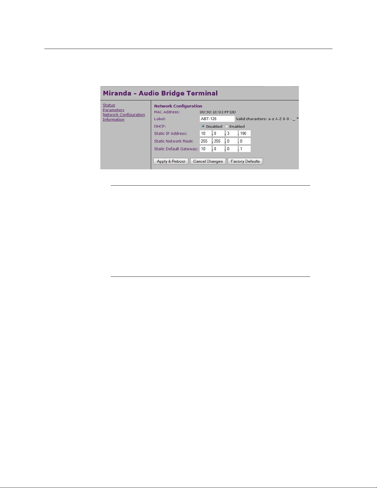
The home page of the ABT’s built-in Web server is displayed.
6Click Network Configuration (in the navigation pane).
The Network Configuration page is displayed.
7 Change the ABT’s network settings, as necessary, and then click Apply & Reboot.
Notes
• The Kaleido-Modular-X supports one ABT device. With the current KaleidoModular-X (3RU) models, you can achieve redundancy by connecting the
ABT to more than one input card, in which case the Kaleido-Modular-X
uses the signal from the input card that is the farthest from the output
cards (i.e., Input
cards, Input
• Keep in mind that all ABTs ship with the same default static IP address. If
you are adding more than one ABT to your network and do not use DHCP,
make sure to assign each ABT a different static IP
connecting them to the network.
D, if you have 4 input cards, Input C if you have 3 input
B if you have 2 input cards).
address before
For more information about the ABT, refer to the Audio Bridge Terminal Guide to Installation
and Operation, available on the DVD that shipped with your system.
Configuring a Client PC
The client PC that you will use to communicate with the Kaleido-Modular-X multiviewer (via
XAdmin and XEdit), and the multiviewer itself, must have IP
subnet. The following procedure applies to a typical Windows
Windows
Changing an IP Address on Windows 7 or Windows 8
To change the IP address of a client PC that has Windows 7 or Windows 8
1 Press the Windows key on your keyboard, type “control panel” and then press Enter.
2 In the search box, type “adapter”, and then, under Network and Sharing Center, click
3In Network Connections, right-click the network adapter you wish to configure (e.g.,
36
XP, see Changing an IP Address on Windows XP, on page 38.
View network connections.
Local Are a Connection, or Ethernet), and then click Properties. If the system prompts you
for an administrator password or confirmation, type the password or provide
confirmation.
addresses within the same
7 or Windows 8 system. For
Page 41

The Properties window for the selected network adapter opens.
Kaleido-Modular-X
Quick Start Guide
4On the Networking tab, under This connection uses the following items, click
Internet Protocol Version 4 (TCP/IPv4), and then click Properties.
The Internet Protocol Version 4 (TCP/IPv4) Properties window opens.
5On the General tab, click Use the following IP address.
6 Type an IP address in the same range as the multiviewer’s current IP address.
For example, if the multiviewer’s IP address is 192.168.3.31, then the IP address of your
client PC could be 192.168.3.123. If you are unsure, contact your network administrator.
7 Type a subnet mask in the same range as that of the multiviewer.
8Click OK.
9In Local Area Connection Properties, click Close.
37
Page 42
Setting Up Your Kaleido-Modular-X System
XEdit Installation
Changing an IP Address on Windows XP
To change the IP address of a client PC that has Windows XP
1On the Start menu, point to Control Panel, right-click Network Connections, and then
click Open on the menu.
2In Network Connections, right-click Local Area Connection, and then click Properties
on the shortcut menu.
3In Local Area connection Properties, select Internet Protocol (TCP/IP) from the list on
the General tab, and then click Properties.
The Internet Protocol (TCP/IP) Properties window opens.
4On the General tab, click Use the following IP address.
5 Type an IP address in the same range as the multiviewer’s current IP address.
For example, if the multiviewer’s IP address is 10.0.3.70, then the IP address of your
client PC could be 10.0.3.123. If you are unsure, contact your network administrator.
6 Type a subnet mask in the same range as that of the multiviewer.
7Click OK.
8In Local Area Connection Properties, click Close.
Step 3: XEdit Installation
XEdit is a client application used to create layouts for the monitor wall, and to configure
your multiviewer system, from your PC or laptop. When the computer with XEdit is
connected to the multiviewer through a TCP/IP network, you can use XEdit to modify
layouts and settings directly on the multiviewer, or you can work locally on the computer
and then export your changes to the multiviewer.
To install XEdit from your multiviewer’s home page
1 From a workstation on the same subnet as the multiviewer, open a Web browser
window and type the multiviewer’s IP address in the address bar.
The multiviewer’s home page appears.
38
2Click the XEdit button.
Page 43

Kaleido-Modular-X
Quick Start Guide
The browser prompts you to save an executable file to your hard drive (Kaleido-
1
windows32-online.exe
). This file is an online installer, which will download XEdit and
other companion elements from your multiviewer, and install them. Some browsers
may allow you to run the file directly. Depending on your browser’s security features,
warnings may appear, which you may safely dismiss.
3 Unless your browser let you run the file (and you chose to do so), navigate to the
location were you saved the installer file and open it.
More security warnings or prompts may appear, which you may safely dismiss or
accept.
A window appears, showing the download and installation progress.
At the end of the installation process:
• If you have Windows 7, or Windows XP, shortcuts ( ) are added to your desktop
and to the Start menu (under All Programs).
• If you have Windows 8.1, or Windows 8, XEdit will appear on your desktop, in the
Apps view with all the other applications on your PC (Windows
screen (Windows
8).
8.1), or in your Start
Once the installation has completed, the XEdit startup screen appears.
1.Installers for Linux or Mac OS X are not yet available.
39
Page 44

Setting Up Your Kaleido-Modular-X System
XEdit Installation
Depending on your Windows Firewall settings, a security alert may appear.
•Click Allow access to unblock the application.
If XEdit cannot find all of the fonts it needs already on your PC or laptop, it downloads
them from the multiviewer automatically, in which case a message will appear to
confirm the font update, and instruct you to restart the application.
40
•Click OK to continue, and then open XEdit again, by using the shortcut on your
desktop, in your Apps view (Windows
8.1) or Start screen (Windows 8), or from the
Start menu (Windows 7, Windows XP).
4 When prompted to specify a database, choose one from the Path list, or click Browse to
navigate to the database you wish to use as your local workspace, and then click OK.
Once the database has completed loading, XEdit’s main application window appears.
Page 45

Kaleido-Modular-X
Quick Start Guide
Note: Once it has been installed from the multiviewer, XEdit remains on
your PC or laptop, and can be launched from the
to your desktop, Apps view, or Start screen (see page 39), or from the Start
menu. Whenever you install a new version of the Kaleido-X software on the
multiviewer, the next time you open XEdit, your installed copy of the
application will be automatically updated from the multiviewer.
For more information about calibrating your system, configuring rooms, creating layouts,
and operating the monitor wall, refer to the Kaleido-X User’s Manual, available on the DVD
that shipped with your system, and from Grass Valley’s support portal.
Step 4: System Verification
Verifying the Kaleido-Modular-X Multiviewer Status
You can check internal system statuses via the Web-based XAdmin application.
To verify the status of your Kaleido-Modular-X multiviewer
1 Open a Web browser window and type your multiviewer’s system IP address (the
address you configured for Output A, in the case of a single- or dual-head system
IP
step 14 on page 26), or the virtual IP address you configured at step 4 on page 28,
(see
in the case of a quad-head system) in the address bar.
The Kaleido-X home page appears.
shortcut that was added
41
Page 46
Setting Up Your Kaleido-Modular-X System
System Verification
2 Click the XAdmin button.
3 If you see a security warning, or a certificate error message, then refer to Registering
your Multiviewer's Security Credentials with your Browser, in the Kaleido-X User’s Manual.
4 If the “Log in to XAdmin” page appears, type the password, and then click Log in.
5 Internet Explorer users: If a blank page appears, then refer to Enabling the
Compatibility View in Internet Explorer 10, in the Kaleido-X User’s Manual.
The XAdmin Status and Options page appears, displaying a list of all modules and their
statuses.
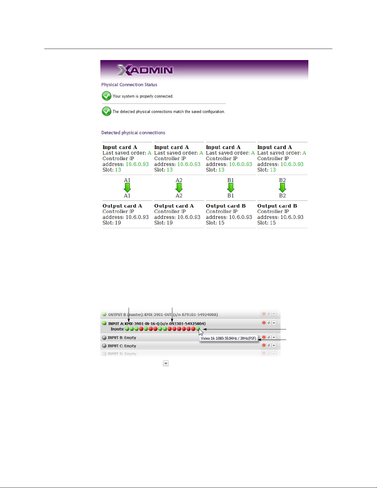
6Click Physical connections, in the navigation area on the left of the page.
The Physical Connections page appears, showing the current connection status for
your system, with a visual representation of the physical connections between the
detected input cards and the output cards associated with the frame IP
address.
42
Page 47
Kaleido-Modular-X
Card type Serial number
Input signal status
Input signal format
Quick Start Guide
7 Review the information on this page, to make sure your input and output cards are all
properly interconnected. Information in red indicates the location where a problem
was detected.
8Click Status and options, in the navigation area on the left of the page, to go back to
the Status and Options page.
The module headings show the card type and serial number for the input and output
cards, and a summary view of the input signals for each input card.
9 Move the pointer to an input signal status icon to view the associated signal format.
10 Click the arrow button ( ) at the end of a module’s heading row to view detailed
information.
43
Page 48

Setting Up Your Kaleido-Modular-X System
Expand details
Refresh
Reset card
System Verification
11 Review the enabled input and output options, and the main system statuses of the
Kaleido-Modular-X frame, to make sure that there are no status errors, and no alerts
related to system temperature, fan operation, FlexBridge connectivity, or card fault
conditions.
Notes
• At any time you can click the Refresh button to make sure the data
displayed for the selected card is up to date. Click the Reset card button at
the end of a card’s heading row to reset the card remotely, directly from
your Web browser.
•See Managing Hardware and Software Options, in the Kaleido-X User’s
Manual, for more information on the available options.
Verifying the Kaleido-RCP2
To verify that the Kaleido-RCP2 is functioning normally
• Log on to the Kaleido-RCP2 (see Using the Kaleido-RCP2 with Default Settings, on
page 33), and then test various operations using the Kaleido-RCP2 keyboard and the
mouse (e.g. load a predefined layout).
Loading a Layout
To load a layout on the monitor wall
1 Connect a mouse to the Kaleido-RCP2 (if available) and log on to the appropriate room,
if you have not already done so (see
page 33).
Alternatively, connect the mouse directly to the USB port at the front of one of your
system’s output card.
2 Right-click anywhere on the monitor wall, point to Monitor wall (if you clicked a
monitor), and then click Load layout on the menu.
Using the Kaleido-RCP2 with Default Settings, on
44
Monitor wall shortcut menu
Page 49

A layout browser appears on the displays associated with the current room.
3 Select the layout you wish to load from the list of available layouts for this room, and
then click OK.
The selected layout appears on the room displays.
Verifying the Audio Bridge Terminal
To verify that the ABT is functioning normally
• Inspect the ACTIVITY and front panel LEDs on the unit to make sure there are no error
conditions:
The ACTIVITY indicator is located on the right-hand side of the rear panel. This LED
reports the status of the Ethernet connection as indicated in the table below.
Two LEDs are visible on the front panel, one for each power supply. When lit, they both
indicate the same status.
When the ABT is powered up, all three LEDs will be orange until the boot sequence is
terminated. This is a visual indicator that the LEDs are functioning properly.
ACTIVITY Indicator on Rear Panel Power-Supply LEDs on Front Panel
Color Status Color Status
Kaleido-Modular-X
Quick Start Guide
Off No link detected Green Normal
Green Normal (good link) Flashing green Normal, rebooting
Orange Activity Orange Warning
Red Hardware fault Flashing orange Warning, rebooting
Flashing red Upgrading firmware Red Hardware fault
Flashing red Upgrading firmware
Verifying the Multiviewer’s IP Addresses and Application Version
Finding the System IP Address
To find your multiviewer’s system IP address
1 Press the Select button on the front edge of a Kaleido-Modular-X output card.
The Status LED on the selected card flashes orange, and the associated control menu
appears on the display of the Densité frame’s local control panel.
2 On the local control panel, press the [–] button repeatedly until NETWORK SETTINGS
appears on the display, and then press the SEL button.
45
Page 50

Setting Up Your Kaleido-Modular-X System
System Verification
FRAME IP ADDRESS EDIT appears on the control panel’s display.
3 Press the SEL button again.
The current system IP address appears on the display. This is your system’s virtual
address (i.e., the address you will use to access your system from XEdit and XAdmin).
IP
4 Press the Select button on the front edge of the output card to exit the control menu.
Verifying an Output Card’s IP Address and Application Version
To verify the IP address and application version on an output card
1 Press the Select button on the front edge of the Kaleido-Modular-X output card.
The Status LED on the selected card flashes orange, and the associated control menu
appears on the display of the Densité frame’s local control panel.
2 Note the position indication A or B in the card information shown on the first line of the
LCD display: either KMX-OUTA, or KMX-OUTB, followed with the slot number (e.g., KMXOUTA Slot 4).
3 On the local control panel, press the [–] button.
The version of the Kaleido-X Software that is running on the card (e.g. “7.10build.5201”) appears on the display.
4 On the local control panel, press the [–] button repeatedly until NETWORK SETTINGS
appears on the display, and then press the SEL button.
FRAME IP ADDRESS EDIT appears on the control panel’s display.
5 If the card was identified as KMX-OUTA on the display, then press the [–] button
repeatedly until OUTPUT A IP EDIT appears. If the card is identified as KMX-OUTB, then
press the [–] button until OUTPUT B IP EDIT appears.
6 Press the SEL button.
The current IP address for this card appears on the display.
46
Note: If you have a single- or dual-head Kaleido-Modular-X multiviewer,
then this IP
address doubles as the system IP address.
7 Press the Select button on the front edge of the output card to exit the control menu.
Verifying an Input Card’s Application Version
To verify the application version on an input card
1 Press the Select button on the front edge of the Kaleido-Modular-X input card.
Page 51

Kaleido-Modular-X
Select button
Status LED
Quick Start Guide
The Status LED on the selected card flashes orange, and the associated control menu
appears on the display of the Densité frame’s local control panel.
2 On the local control panel, press the [–] button.
The version of the Kaleido-X Software that is running on the card (e.g. “7.10build.5201”) appears on the display.
3 Press the Select button on the front edge of the input card to exit the control menu.
RS-422 Connection Diagram
Output cards paired with a double rear connector panel support one RS-422 port over an
RJ-45 connector. This port allows the Kaleido-Modular-X to connect to external serial
devices such as a router, production switcher, or router controller.
Notes
• The single rear connector panel KMX-3901-OUT-D-3+SRP does not have a
serial port. To support a serial device, your Kaleido-Modular-X system must
have at least one output card with a double rear connector panel
(KMX-3901-OUT-D-3DRP).
• The RS-422 ports each have an RJ-45 connector in order to preserve space
on a busy panel. The RS-422 interface specifies a DE-9 connector, so if you
are using this interface, you will require a DE-9-to-RJ-45 adapter. Grass
Valley supplies two adapter models, correctly wired for this application: a
straight adapter (part no. 1737-3000-102), and a crossover adapter (part
no. 1792-3700-100).
The pinout for the RS-422 signals on the RJ-45 connectors, and the wiring diagrams for the
appropriate adapters, are shown here:
47
Page 52

Setting Up Your Kaleido-Modular-X System
Pinout of each RS-422
port’s RJ-45 connector
on the multiviewer
Pinout of straight adapter (Grass
Valley part no. 1737-3000-102)
RJ-45 DE-9 male DE-9 female
Pinout of RS-422
connector on SMPTE
slave device
Pinout of each RS-422
port’s RJ-45 connector
on the multiviewer
RJ-45 DE-9 male DE-9 female
Pinout of crossover adapter (Grass
Valley part no. 1792-3700-100)
Pinout of RS-422
connector on SMPTE
master device
RS-422 Connection Diagram
Standard wiring between multiviewer and devices wired to SMPTE “slave” specification (e.g. most
routers, Ross Synergy switchers, Nevion ETH-CON)
Standard wiring between multiviewer and devices wired to SMPTE “master” specification (e.g. Philips
Jupiter router control system, Grass Valley Presmaster PCS)
Note: The two RS-422 ports on the multiviewer side have no ground pin.
Using the appropriate DE-9S-to-RJ-45 adapter, an external device should be
able to communicate with a multiviewer despite the lack of a ground.
For more information about the RS-422 specifications, see the “Communication” section in
the Specifications chapter of the Kaleido-Modular-X Hardware Description & Installation
Manual. For more information about the RS-422 serial connections, see the “Serial
Connections” section in the Routers chapter of the Kaleido-Modular-X User’s Manual.
48
Page 53

Grass Valley Technical Support
For technical assistance, contact our international support center, at
1-800-547-8949 (US and Canada) or +1 514 333 1772.
To obtain a local phone number for the support center nearest you, please consult the
Contact Us section of Grass Valley’s Web site (
An online form for e-mail contact is also available from the Web site.
Corporate Head Office
Grass Valley
3499 Douglas-B.-Floreani
St-Laurent, Quebec H4S 2C6
Canada
Telephone: +1 514 333 1772
Fax: +1 514 333 9828
www.grassvalley.com
Contact Us
www.grassvalley.com).
 Loading...