

Page 1
K2
Media Platform
System Guide
Software Version 7.2
071-8726-01
April 2010
Page 2

Affiliate with the N.V. KEMA in The Netherlands
CERTIFICATE
Certificate Number: 510040.001
The Quality System of:
Thomson Inc, and it’s wordwide Grass Valley division affiliates DBA
GRASS VALLEY
Headquarters
400 Providence Mine Rd
Nevada City, CA 95959
United States
15655 SW Greystone Ct.
Beaverton, OR 97006
United States
10 Presidential Way
Suite 300
Woburn, MA 01801
United States
Kapittelweg 10
4827 HG Breda
The Nederlands
7140 Baymeadows Way
Ste 101
Jacksonville, FL 32256
United States
2300 So. Decker Lake Blvd.
Salt Lake City, UT 84119
United States
Rue du Clos Courtel
CS 31719
35517 Cesson-Sevigné Cedex
France
1 rue de l’Hautil
Z.I. des Boutries BP 150
78702 Conflans-Sainte
Honorine Cedex
France
Technopole Brest-Iroise
Site de la Pointe du Diable
CS 73808
29238 Brest Cedex 3
France
40 Rue de Bray
2 Rue des Landelles
35510 Cesson Sevigné
France
Spinnereistrasse 5
CH-5300 Turgi
Switzerland
Brunnenweg 9
D-64331 Weiterstadt
Germany
Carl-Benz-Strasse 6-8
67105 Schifferstadt
Germany
Including its implementation, meets the requirements of the standard:
ISO 9001:2008
Scope:
The design, manufacture and support of video and audio hardware and software products and
related systems
.
This Certificate is valid until: June 14, 2012
This Certificate is valid as of: June 14, 2009
Certified for the first time: June 14, 2000
H. Pierre Sallé
President
KEMA-Registered Quality
The method of operation for quality certification is defined in the KEMA General Terms
And Conditions For Quality And Environmental Management Systems Certifications.
Integral publication of this certificate is allowed.
KEMA-Registered Quality, Inc.
4377 County Line Road
Chalfont, PA 18914
Ph: (215)997-4519
Fax: (215)997-3809
CRT 001 073004
ccredited By:
ANAB
A
Page 3

K2
Media Platform
System Guide
Software Version 7.2
071-8726-01
April 2010
Page 4

Copyright Copyright © Grass Valley, Inc. All rights reserved. Printed in the United States of America.
Portions of software © 2000 – 2010, Microsoft Corporation. All rights reserved. This document
may not be copied in whole or in part, or otherwise reproduced except as specifically permitted
under U.S. copyright law, without the prior written consent of Grass Valley, Inc., P.O. Box
59900, Nevada City, California 95959-7900. This product may be covered by one or more U.S.
and foreign patents.
Disclaimer Product options and specifications subject to change without notice. The information in this
manual is furnished for informational use only, is subject to change without notice, and should
not be construed as a commitment by Grass Valley, Inc. Grass Valley, Inc. assumes no
responsibility or liability for any errors or inacc uracies that may appear in this publication.
U.S. Government
Restricted Rights
Legend
Trademarks and
Logos
Revision Status
Use, duplication, or disclosure by the United States Government is subject to restrictions as set
forth in subparagraph (c)(1)(ii) of the Rights in Technical Data and Computer Software clause
at DFARS 252.277-7013 or in subparagraph c(1) and (2) of the Commercial Computer
Software Restricted Rights clause at FAR 52.227-19, as applicable. Manufacturer is Grass
Valley, Inc., P.O. Box 59900, Nevada City, California 95959-7900 U.S.A.
Grass Valley, K2, Aurora, Summit, Dyno, Solo, Infinity, Turbo, Profile, Profile XP, NetCentral,
NewsBrowse, NewsEdit, NewsQ, NewsShare, Ne wsQ Pro, and Media Manager are either
registered trademarks or trademarks of Grass Valley, Inc. in the United States and/or other
countries. Grass Valley, Inc. products are covered by U.S. and foreign patents, issued and
pending. Additional information regarding Grass Valley, Inc. trademarks and other proprietary
rights may be found at www.grassvalley.com. Other trademarks and logos used in this
document are either registered trademarks or trademarks of the manufactu rers or vendors of
the associated products, such as Microsoft® Windows® operating system, Windows Media®
player, Internet Explorer® internet browser, and SQL Server™. QuickTime and the QuickTime
logo are trademarks or registered trademarks of Apple Computer, Inc., used under license
therefrom.
Rev Date Description
November 2005 –
July 2007
Initial release and revisions for 3.1 and 3.2 releases —
071-8460-00, 071-8460-02, 071-8460-03
September 7,
2007
January 11, 2008 Added information for capture services and Type II motherboard —
July 28, 2008 Added information for software version 3.2.7, XML Import capture
March 20, 2009 Version for K2 Summit Client, removed K2 Media Client-specific
October 27, 2009 Added K2 Solo Media Server, MPEG-2, AVC-Intra and other
April 7, 2010 Added ChannelFlex Suite features, K2 Transmission, and other
Revised information for direct-connect storage, teaming, HotBins,
software version 3.2.5 — 071-8460-03
071-8460-04
service, ancillary/data track specs ,MIBs — 071-8460-05
information — 86231160
information for software version 7.1 — 071-8726-00
information for software version 7.2 — 071-8726-01
4 K2 System Guide 07 April 2010
Page 5

Contents
Finding Information...........................................................................................11
Grass Valley Product Support.................................................................................15
Web Technical Support ......................................................................................15
Telephone Support.............................................................................................15
Waste Electrical and Electronic Equipment Directive.........................................17
Chapter 1 Product Description
K2 Summit Production Client and K2 Solo Media Server features .........................20
Features of internal storage models...................................................................21
Features of external storage models..................................................................21
Product identification...............................................................................................22
Front panel indicators.................................................... ...... ....................................23
Rear panel view.......................................................................................................24
K2 Summit Production Client rear panel........................................................ 24
K2 Solo Media Server rear panel.....................................................................25
ChannelFlex Suite rear panel connections...................................................26
Considerations for first startup out of box................................................................26
K2 Summit Production Client and K2 Solo Media Server system overview............27
Application System.............................................................................................27
Real Time System..............................................................................................27
Media control and processing.............................................................................27
Loop through, E to E, and feeds.........................................................................28
Ports used by K2 services..................................................................................30
RAID drive numbering........................................................................................31
Chapter 2 Using K2 system tools
Configuration Manager............................................................................................33
Accessing Configuration Manager......................................................................33
Saving and restoring Configuration Manager settings .......................................33
Restoring default Configuration Manager settings ............................................34
K2 System Configuration.........................................................................................35
Storage Utility..........................................................................................................36
NetCentral...............................................................................................................37
Windows Remote Desktop Connectio n...................................................................37
................................................................................................................................38
SiteConfig — a ProductFrame application..............................................................38
Chapter 3 System connections and configuratio n
About networks............................................. ....................................... ...... ...... ..... ...42
Control network description................................................................................42
Streaming/FTP network description ...................................................................42
Media (iSCSI) network description.....................................................................42
Network connections...............................................................................................43
Cable requirements............................................................................................43
About network ports....................................... ....................................... ...... ..... ...43
Making network connections..............................................................................44
Network configuration..............................................................................................45
About network functionality............................................................. ....................45
About modifying or restoring network settings....................................................46
Configure network settings for a stand-alone K2 systems .................................46
Streaming video between K2 systems ...............................................................48
Using FTP for file transfer .......................................................................................52
About the K2 FTP interface................................................................................53
Limitations with complex media types................................................................53
Transferring between different types of systems................................................53
Transfer mechanisms............................................... ...... ..... ...............................53
FTP access and configuration............................................................................54
07 April 2010 K2 System Guide 5
Page 6

Contents
FTP access by automation................................................................................. 54
FTP security....................................................................................................... 55
FTP internationalization...................................................................................... 55
FTP access by Internet Explorer........................................................................ 56
FTP commands supported.................................................................................59
Using FTP on a K2 Nearline SAN............................................ ...... ..... ...... ...... ...60
Using the HotBin service......................................................................................... 61
About the HotBin service....................................................................................61
Prerequisite for using the HotBin service...........................................................62
Configuring the HotBin service........................................................................... 62
HotBin service components..................... ..... ...... ..... ........................................... 65
Using the Pathfire capture service.......................................................................... 66
About the Pathfire capture service..................................................................... 66
Prerequisites for using the Pathfire capture service...........................................66
Considerations for the Pathfire capture service ................................................. 67
Configuring the Pathfire capture service............................................................ 67
Testing the Pathfire capture service................................................................... 69
Pathfire capture service components................................................................. 69
Pathfire capture service procedures................... ..... ........................................ ...70
Installing Pathfire Transfer Service software......................................................70
Licensing Pathfire Transfer Service software..................................................... 73
Using the DG capture service .................................................................................75
About the DG capture service....................................... ...... ...............................75
Prerequisites for using the DG capture service.................................................. 75
Configuring the DG capture service...................................................................76
Testing the DG capture service.......................................................................... 77
DG capture service procedures..........................................................................78
DG capture service components........................................................................ 78
Using the XML Import capture service.................................................................... 79
About the XML Import capture service............................................................... 79
Prerequisites for using the XML Import capture service.....................................79
Considerations for the XML Import capture service ...........................................80
Configuring the XML Import capture service...................................................... 80
Testing the XML Import capture service.............................................................82
XML Import capture service components........................................................... 82
Using the P2 Import capture service....................................................................... 83
About the P2 Import capture service.................................................................. 83
Prerequisites for using the P2 Import capture service........................................83
Considerations for the P2 Import capture service..............................................84
Configuring the P2 Import capture service......................................................... 84
Testing the P2 Import capture service................................................................86
P2 Import capture service components.............................................................. 86
Licensing K2 capture service software.................................................................... 86
Pinnacle support.....................................................................................................87
Compressed VBI import.......................................................................................... 92
About compressed VBI import processes..........................................................92
Specifications..................................................................................................... 92
................................................................................................................................93
Quicktime and Final Cut Pro support...................................................................... 93
About connecting to K2 storage with Final Cut Pro............................................ 93
Install and configure Macintosh Final Cut Pro systems on K2 storage.............. 94
Using Final Cut Pro on a K2 storage..................................................................104
Connecting RS-422............................................................ ...... ..... .......................... 105
Connecting GPI.................................................................. .....................................106
Chapter 4 Managing Stand-alone Storage
About the internal storage system........................................................................... 107
6 K2 System Guide 07 April 2010
Page 7

K2 Summit Production Client internal storage system.......................................107
K2 Solo Media Server internal storage system ..................................................107
About the direct-connect sto rage system................................. ...............................108
Using Storage Utility................................................................................................109
About Storage Utility............................................................ ...... .........................110
Opening Storage Utility.......................................................................................110
Overview of Storage Utility .................................................................................112
Checking storage subsystem status...................................................................113
Checking controller microcode...........................................................................113
About identifying disks.............................................. ...... ..... ...... .........................114
Identifying internal disks.....................................................................................114
Get controller logs .............................................. ...... ...... ..... ...............................115
Check disk mode pages.....................................................................................115
Disabling a disk ..................................................................................................115
Forcing a disk to rebuild .....................................................................................116
Unbind LUN........................................................................................................116
Bind Luns............................................................................................................117
Changing RAID type for internal storage............................................................119
Making a new media file system on a K2 Summit/Solo......................................120
Checking the media file system..........................................................................120
Cleaning unreferenced files and movies ............................................................121
Downloading controller microcode .....................................................................121
Downloading disk drive firmware........................................................................122
Placing the K2 system into online mode.............................................................123
Chapter 5 Managing stand-alone K2 systems with SiteConfig
About managing stand-alone K2 clients with SiteConfig.........................................126
SiteConfig and stand-alone K2 clients checklist......................................................126
System requirements for SiteConfig con trol poi nt PC.............................................127
About installing SiteConfig...................................... ...... ...... ....................................128
Installing/upgrading SiteConfig................................................................................128
Creating a system description for stand-alone K2 clients .......................................130
Creating the control network for stand-alone K2 clients..........................................131
Creating the FTP/streaming network for stand-alone K2 clients (optional).............133
Adding a group........................................................................................................134
Adding stand-alone K2 clients to the system description........................................134
Modifying stand-alone K2 client unassigned (unmanaged) interfaces....................135
Discovering devices with SiteConfig .......................................................................137
Assigning discovered devices.................................................................................138
Modifying stand-alone K2 client managed network interfaces................................139
Adding a control point PC placeholder device to the system description................144
Assigning the control point PC................................................................................145
Making the host name the same as the device name..................................... ........146
Pinging devices from the control point PC ..............................................................146
About hosts files and SiteConfig .............................................................................146
Generating host tables for devices with SiteConfig.................................................147
Configuring deployment groups ..............................................................................148
About deploying software for stand-alone K2 clients ..............................................149
Chapter 6 Managing K2 system software
About K2 system software.......................................................................................151
Software components installed...........................................................................152
Installing Control Point software..............................................................................152
Installing K2 software..............................................................................................154
Pre-installed software..............................................................................................154
Backup and recovery strategies..............................................................................154
07 April 2010 K2 System Guide 7
Page 8

Contents
Chapter 7 Administering and maintaining the
K2 system
About the write filter................................................................................................ 155
Enabling the write filter............................................................................................ 156
Disabling the write filter...........................................................................................156
Committing a file to disk with write filter enabled.................................................... 156
Licensing.................................................................................................................157
Software version licenses...................................................................................157
Licensable options.............................................................................................. 157
Configuring K2 security...........................................................................................158
Overview of K2 security features........................................................................ 159
Example: Setting up user access to bins ........................................................... 160
Example: Setting up user access to channels....................................................160
Security and user accounts................................................................................ 161
Configuring media access security for K2 bins.................................................. 161
AppCenter operations and media access security............................................. 163
FTP and media access security .........................................................................163
K2 SANs and media access security ................................................................. 164
Protocol control of channels and media access security....................................164
Configuring channel access security.................................................................. 165
K2 and NetCentral security considerations............................................................. 167
Mapping a NetCentral administrator to the K2 administrator level..................... 167
Microsoft Windows updates................... ...... ....................................... .................... 168
Virus scanning policies............................................................................................ 169
Network and firewall policies................................................................................... 169
Enabling and disabling the USB ports.....................................................................170
Configuring auto log on...........................................................................................171
Regional and language settings.............................................................................. 171
Chapter 8 Direct Connect Storage
Setting up direct-connect RAID storage..................................................................173
Powering up K2 RAID.............................................................................................177
Chapter 9 K2 Summit Transmission Server Package
K2 Summit Transmission Server Package features................................................ 179
K2 Summit Transmission Server Package requirements and restrictions.............. 180
Storage Utility procedures for the K2 Summit Transmission Server Package........ 180
Appendix A Remote control protocols
Using AMP protocol to control K2 systems............................................................. 182
Using VDCP protocol to control K2 systems........................................................... 183
Using BVW protocol to control K2 systems............................................................. 185
Special considerations for automation vendors ......................................................186
Harris settings .................................................................................................... 186
RS-422 connections on the K2 Summit Production Client or K2 Solo Media Server187
Security and protocol control................................................................................... 187
Appendix B Specifications
AC power specification............................................................................................190
Environmental specifications................................................................................... 190
Mechanical specificati on s....................................... ..... ...... ...... ...............................192
Electrical specifications................................ ..... ...... ....................................... ......... 192
Serial Digital Video (SDI).................................................................................... 192
Genlock Reference.................................. ..... ...... ..... ........................................... 193
System Timing.......................................................................... ...... ..... ...... ......... 194
AES/EBU Digital Audio....................................................................................... 194
LTC Input/Output................................................................................................ 196
8 K2 System Guide 07 April 2010
Page 9

VITC Input/Output...............................................................................................196
RS-422 specification...........................................................................................196
GPI I/O specifications.........................................................................................197
Operational specifications.......................................................................................198
Video codec description K2 Summit/Solo...........................................................199
Playout of multiple formats .................................................................................200
Active Format Description (AFD) specifications.................................................203
VBI/Ancillary/data track specifications................................................................210
Internationalization.............................................................................................214
Naming specifications for assets and bins .........................................................214
Video network performance................................................................................216
Supported file input/output formats on K2 Summit/Solo/SAN ............................216
MXF export behavior on K2 Summit/Solo ..........................................................218
Media file system performance on K2 systems..................................................218
Transition effects formats suppo rted.................................................... ...... ..... ...219
Protocols supported............................................................................................220
Transfer compatibility with K2 Summit/Solo.......................................................221
Control Point PC system requirements ..............................................................224
MIB specifications...................................................................................................225
K2 client MIBs.....................................................................................................226
K2 Media Server MIBs........................................................................................227
K2 Appliance (Generic Windows computer based) MIBs...................................228
................................................................................................................................229
Appendix C Connector Pinouts
K2 Summit Production Client connector pinouts.....................................................232
AES Audio..........................................................................................................232
RS-422 connector pinouts..................................................................................233
LTC connectors pinouts......................................................................................234
GPI I/O connector pinouts ..................................................................................235
K2 Media Client connector pinouts..........................................................................236
RS-422 connector pinouts..................................................................................236
LTC connectors pinouts......................................................................................237
GPI I/O connector pinouts ..................................................................................238
K2 Media Server connector pinouts........................................................................239
Redundant server heartbeat cable.....................................................................239
Appendix D Rack mounting
Rack-mount considerati ons................................ ...... ...... ....................................241
Rack mount hardware shipped with the K2 system............................................242
Mounting the Rack Slides...................................................................................243
Installing the K2 system on the rack mount rails ................................................244
Making Rack Slide Adjustments.........................................................................245
Index......................................................................................................................247
07 April 2010 K2 System Guide 9
Page 10

Contents
10 K2 System Guide 07 April 2010
Page 11

Finding Information
This manual describes K2™ systems and provides the information you need to go
beyond factory default settings and customize your system’s configuration to meet
your site-specific needs. The manual covers K2 Summit™ Production Client, K2
Solo™ Media Server, including ChannelFlex™ S uit e f ea tur es , an d K2 SAN devices.
How this manual is org anized
This manual is organized around the tasks required to install and configure K2
systems. The following chapters are include d in this manual:
Chapter 1, Product Description
Chapter 2, Using K2 system tools
Chapter 3, System connections and configuration
Chapter 4, Managing Sta nd- alo ne Stor age
Chapter 6, Managing K2 system software
Chapter 7, Administering and maintaining the K2 system
Chapter 8, Direct Connect Storage
Chapter 9, K2 Summit Transmission Server Package
Appendix A, Remote cont rol protocols
Appendix B, Specifications
Appendix C, Connector Pinouts
Appendix D, Rack mounting
07 April 2010 K2 System Guide 11
Page 12

Finding Information
Getting more information
The following sections help you find the information you need in product manuals
and elsewhere.
For the installer of a K2 product with internal storage
If you are install ing a K2 clien t with st and-alone in terna l stor age or a K2 Solo Medi a
Server, refer to documentation in the following sequence:
Find this document… I n these locations… In these formats:
1 K2 Release Notes K2 product shipping box Printed
2 Quick Start Guide for the K2 product K2 product shipping box Printed
3 K2 System Guide K2 Documentation CD PDF file
Grass Valley Website PDF file
K2 Documentation CD PDF file
Grass Valley Website PDF file
Grass Valley Website PDF file
For the installer of a K2 client with direct connect storage
If you are installing a K2 client with stand-alone direct connect storage, refer to
documentation in the following sequence:
Find this document… I n these locations… In these formats:
1 K2 Release Notes K2 product shipping box Printed
Grass Valley Website PDF file
2 K2 Storage Cabling Guide K2 RAID shipping box Printed
K2 Documentation CD PDF file
Grass Valley Website PDF file
2 Quick Start Guide for the K2 product K2 product shipping box Printed
K2 Documentation CD PDF file
Grass Valley Website PDF file
3 K2 System Guide K2 Documentation CD PDF file
Grass Valley Website PDF file
12 K2 System Guide 07 April 2010
Page 13

For the installer of K2 clients and K2 SAN shared storage
If you are installing a K2 SAN with connected K2 clients, refer to documentation in
the following sequence:
Find this document… I n these locations… In these formats:
1 K2 Release Notes K2 product shipping box P r inted
Grass Valley Website PDF file
2 K2 Storage Cabling Guide K2 RAID shipping box Printed
K2 Documentation CD PDF file
Grass Valley Website PDF file
2 Quick Start Guide for the K2 product K2 product shipping box Printed
K2 Documentation CD PDF file
Grass Valley Website PDF file
3 K2 SAN Installation and Service Manual K2 Documentation CD PDF file
Grass Valley Website PDF file
3 K2 System Guide K2 Documentation CD PDF file
Grass Valley Website PDF file
Quick Start Guide
You receive this guide in the product packaging with your K2 product. The Quick
Start Guide provides step-by-step installation instructions for basic installation and
operation of your K2 product, including recording and playing clips.
Release Notes
The K2 Release Notes contain the latest information about the software shipped on
your system. The release notes include software upgrade instructions, software
specifications and r equir ements, f eature ch ange s from the pr evious relea ses, and any
known problems. Because release notes contain the latest information, they are
printed out and included in the K2 product shipping box, rather than included in the
Documentation CD-ROM. You should always check the Grass Valley Website to
determine if there is an updated version of release notes available.
K2 Storage Cabling Guide
The cabling guide provides instructions for K2 Storage Area Network cabling and
external configuration. The cabling guide provides instructions for each pre-defined
level of K2 SAN and cov ers b oth r edundan t and basi c (no n-redu ndan t) syst ems. You
can find the cabling guide packaged with the primary RAID storage chassis.
Documentation CD
Except for the release notes, the full set of support documentation, including this
manual, is availabl e on the K2 Documentat ion CD-ROM tha t you rec eived wit h your
K2 product.
07 April 2010 K2 System Guide 13
Page 14

Finding Information
The K2 Documentation CD includes the following documents:
•
•
•
•
•
•
•
•
K2 AppCenter User Manual — Provides instructions for configuring and operating
the media channels of product.
Quick Start Guides — The Quick Start Guide provides step-by-step installation
instructions for basic installation and operation of the K2 product.
K2 System Guide — Contains the product specifications and instructions for
modifying system settings.
Service Manuals — Contains information on servicing and maintaining the K2
product.
K2 SAN Installation and Service Manual — Contains installa tion, configura tion, and
maintenance procedures for shared storage options.
K2 Storage Cabling Guide — Contains diagrams for cabling the devices of the K2
Summit Production Client.
RAID Instruction Manuals — There is an Instruction Manual for each type of RAID
storage device that c an be a part of a K2 Summit Produc tion Client. These manuals
contain procedures for configuring and servicing the device.
Fibre Channel Switch Installation Manual — Contains information on configuring
and servicing the Fibre Channel switch.
On-line Help Sy st e m s
K2 AppCenter Help — In the AppCenter user interface menu bar selec t Help, then
choose
SiteConfig Help — In the SiteConfig user interface menu bar select Help, then choose
SiteConfig Help Topics from the drop-down menu.
NetCentral Help — From the NetCentr al int erfa ce sel ect He lp | NetCentral Help Topics.
AppCenter Help Topics from the drop-down menu.
NetCentral documentation
The NetCentral product has its own documentation set, described as follows:
•
NetCentral Quick Star t Guide — Pr ovides an overview o f the i nstalla tion proc ess to
quickly set up and run NetCentral.
•
NetCentral Installation Guide — Identifies requirements and procedures to correctly
set up servers and devices, as well as provides detailed instructions to install and
configure NetCentral software.
•
NetCentral User Guide — Describes how to use the NetCentral Manager to monitor
devices.
•
NetCentral Help — From the NetCentral inter face acce ss on-line help. Selec t Help |
NetCentral Help Topics
.
14 K2 System Guide 07 April 2010
Page 15

Grass Valley Web Site
This public Web site contains all the latest manuals and documentation, and
additional support information. Use the following URL.
http://www.grassvalley.com.
Grass Valley Product Support
To get technical assis tance, check on the statu s of a question, or to re port a new issues,
contact Grass Valley Product Support via e-mail, the Web, or by phone or fax.
Web Technical Support
To access support infor mation on the Web, v isit the pr oduct support Web page on the
Grass Valley Web site. You can download software or find solutions to problems.
World Wide Web:http://www.grassvalley.com/support/
Technical Support E-mail Address:gvgtechsupport@grassvalley.com
Grass Valley Product Support
Telephone Support
Use the following information to contact Product Support by phone.
International Support Centers
Our international support centers are available 24 hours a day, 7 days a week.
Support Center Toll free In country
France +800 80 80 20 20 +33 1 48 25 20 20
United States +1 800 547 8949 +1 530 478 4148
Authorized Local Support Representative
A local support represen ta ti ve ma y be avai l abl e in your count ry. To locate a support
center duri ng normal lo cal business hours, refer to the following list. T his list is
regularly updated on the website for Grass Valley Product Support
(http://www.grassvalley.com/support/contact/phone/)
After–hours local phone support is also available for warranty and contract
customers.
07 April 2010 K2 System Guide 15
Page 16

Finding Information
Region County Telephone
Asia China +86 10 5883 7575
Hong Kong, Taiwan, Korea,
Macau
Japan +81 3 6848 5561
Southeast Asia - Malaysia +603 7492 3303
Southeast Asia - Singapore +65 6379 1313
India +91 22 676 10300
Pacific Australia 1 300 721 495
New Zealand 0800 846 676
For callers outside Australia or
New Zealand
Central America, SouthAmerica All +55 11 5509 3440
North America North America, Mexico,
Caribbean
Europe UK, Ireland, Isr a e l +44 118 923 0499
Benelux – Netherlands +31 (0) 35 62 38 421
Benelux – Belgium +32 (0) 2 334 90 30
France +800 80 80 20 20;
Germany, Austria,
Eastern Europe
Belarus, Russia, Tadzhikistan,
Ukraine, Uzbekistan
+852 2531 3058
+61 3 8540 3650
+1 800 547 8949;
+1 530 478 4148
+33148252020
+49 6150 104 444
+7 095 258 09 20;
+33 (0) 2 334 90 30
Nordics (Norway, Sweden,
Finland, Denmark, Iceland)
Southern Europe – Italy Rome: +39 06 87 20 35 28 ; +39
Southern Euro pe – Spain +34 91 512 03 50
Switzerland +41 56 299 36 32
Middle East, Near East, Af r ica Middle East +971 4 299 64 40
Near East and Africa +800 80 80 20 20;
16 K2 System Guide 07 April 2010
+45 40 47 22 37; +32 2 333 00 02
06 8720 35 42. Milan: +39 02 48
41 46 58
+33148252020
Page 17

Waste Electrical and Electronic Equipment Directive
Waste Electrical and Electronic Equipment Directive
07 April 2010 K2 System Guide 17
Page 18

Finding Information
18 K2 System Guide 07 April 2010
Page 19
Chapter 1
!
!
Product Description
The K2™ Summit™ Production Client and K2 Solo™ Media Server are
cost-effective Broadcast Enterpr ise Servers th at incorpora t e IT server platform and
storage technologies to deliver a networked solution to facilities for ingest, playout,
news integration, s por ts , and media asset manage ment . Th ey provides a suite of user
applications and system tools. The manual contains information for all models and
options, including ChanneFlex™ Suite. Refer to the sections that apply to your
particular model and options.
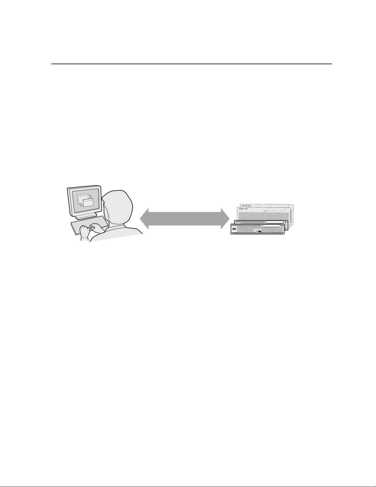
Control
Point PC
K2 Summit Production Clients,
K2 Media Clients, and K2 Solo Media Servers
Operation, configuration, and
monitoring from a remote location
The K2 Summit Production Client and K2 Solo Media Server are designed for
“headless” operation from a remote control point using Grass Valley Control Point
software. You can also use the Microsoft Windows Remote Desktop Connection
application on your PC to connect to the K2 system for configuration or
administration.
The K2 Summit Production Client and K2 Solo Media Server products are further
described in the followi ng sections:
• “K2 Summit Production Client and K2 Solo Media Server features” on page 20
• “Product identification” on page 22
• “Front panel indicators” on page 23
• “Rear panel view” on page 24
• “K2 Summit Production Client and K2 Solo Media Server system overview” on
page 27
Communication over
Ethernet network
K2 SUMMIT
K2 SUMMIT
PRODUCTION
CLIENT
PRODUCTION
CLIENT
Also refer to Chapter 9, K2 Summit Transmission Server Package for information
unique to that product.
07 April 2010 K2 System Guide 19
Page 20

Chapter 1 Product Description
K2 Summit Production Client and K2 Solo Media Server features
The following features apply to the K2 Summit Production Client:
• Two or four channels per chassis
• SDI video inputs and outputs
• AES/EBU or embedded audio inputs and outputs.
• Redundant power supply, cooling fans for reliability
• System dr ive — compact flash protected by a fi le-based write filter
• RAID media storage
• Remote operation and configuration via AppCenter
• NetCentral™ provide s remote error reporting and moni toring via SNMP (Optional
for models using local storage only)
• Gigabit Ethernet
• AMP, VDCP, and BVW remote control protocols supported
• Remote control over RS-422 or Ethernet
• Super Slo-Mo, Mult i-cam, and 3D/Video + Key features are avai lable as part of t he
ChannelFlex Suite
The following features apply to the K2 Solo Media Server:
• Two channels per chassis
• SDI video inputs and outputs
• AES/EBU or embedded audio inputs and outputs.
• System dr ive — compact flash protected by a fi le-based write filter
• RAID 0 media storage
• Remote operation and configuration via AppCenter
• NetCentral™ provide s remote error reporting and moni toring via SNMP (Optional
for models using local storage only)
• Gigabit Ethernet
• AMP, VDCP, and BVW remote control protocols supported
• Remote control over RS-422 or Ethernet
• ExpressCard
• Super Slo-Mo, Mult i-cam, and 3D/Video + Key features are avai lable as part of t he
ChannelFlex Suite
20 K2 System Guide 07 April 2010
Page 21

The K2 Summit Production Client and K2 Solo Media Server have bi-directional
video codecs, which means each channel supports both record and play operations.
You can encode and decode video using the DVCPRO HD, DVCPRO 25/50, or
DVcompression standards. You can also dec ode MPEG-2. Options include MPEG-2
encode and AVC-Intra encode/decode. All channels support Standard Definition
(SD) video and, if licensed, each pair of channels can also support High Definition
(HD) video. For more information on available codecs, see “Operational
specifications” on page 198.
You can play a sequence of clips of diffe rent c ompressi on stan dards an d, if licensed,
HD and SD formats back-to-back on t he same timeline with no chan nel configurati on
changes. Both HD and SD clips are played out in the format specified for the output
assigned to the channel. All clips are either up- or down-converted appropriately to
play on that output, and their aspect ratios are adjusted.
For the K2 Summit Production Client, stand-alone internal storage, stand-alone
external direct-connect storage, and external shared (SAN) storage models are
available.
Features of internal storage models
An internal storage K2 Summit Prod uction Client ca n have eight medi a drives. A K2
Solo Media Server has two media drives. Compact Flash serves as the system drive.
This makes the int ernal st orage K2 system a self- contained , stand-a lone un it, with n o
external devices for storage connection s r equ ir ed. You can transfer media in a nd out
of the internal storage K2 syst em via Gigabi t Ether net. You can al so expor t media to
a mapped drive or USB-attached storage. With the K2 Solo Media Server, you can
also export media via the ExpressCard.
Features of internal storage models
Features of external storage models
The external storage K2 Su mmi t P rodu ct ion Client contains only t he Compact Flash
that serves as the system drive. There are no media drives in an external storage K2
Summit Pro duction Client. There are two types of extern al storage fo r media, as
follows:
• Shared storage — Multiple external storage K2 Summit Production Clients
connect to the K2 SAN via Gigabit Ethernet or Fibre Channel to share a common
pool of storage.
• Direct-connect s torage — A single K2 Summit Production Client with the opt ional
Fibre Channel board installed connects directly to its own external (non-shared)
RAID storage device. This makes t he direct-connect K2 Summit Produ ction Client
a self-contained, stand-alone unit, with no external (non-shared) devices for
storage, audio, or video conn ections require d. You can transfer media in and out of
the direct-connect K2 Summit Production Client via Gigabit Ethernet.
07 April 2010 K2 System Guide 21
Page 22
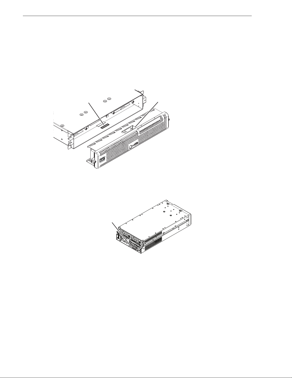
Chapter 1 Product Description
USB compartment
g.
Serial Number
(e.g. K2—01AA00010)
This is also the factory
default hostname
Product identification
The K2 Summit Production Client has labels affixed to the chassis that provide
product identification as in the following diagram:
Serial Number
(e.g. K2—01AA00010)
This is also the factory
default hostname
(Compartment swivels up.)
Note: removing the bezel takes
the fans offline. Replace the bezel assembly
within one minute to maintain system coolin
The K2 Solo Media Server has labels affixed to the chassis that provide product
identification as in the following diagram:
22 K2 System Guide 07 April 2010
Page 23
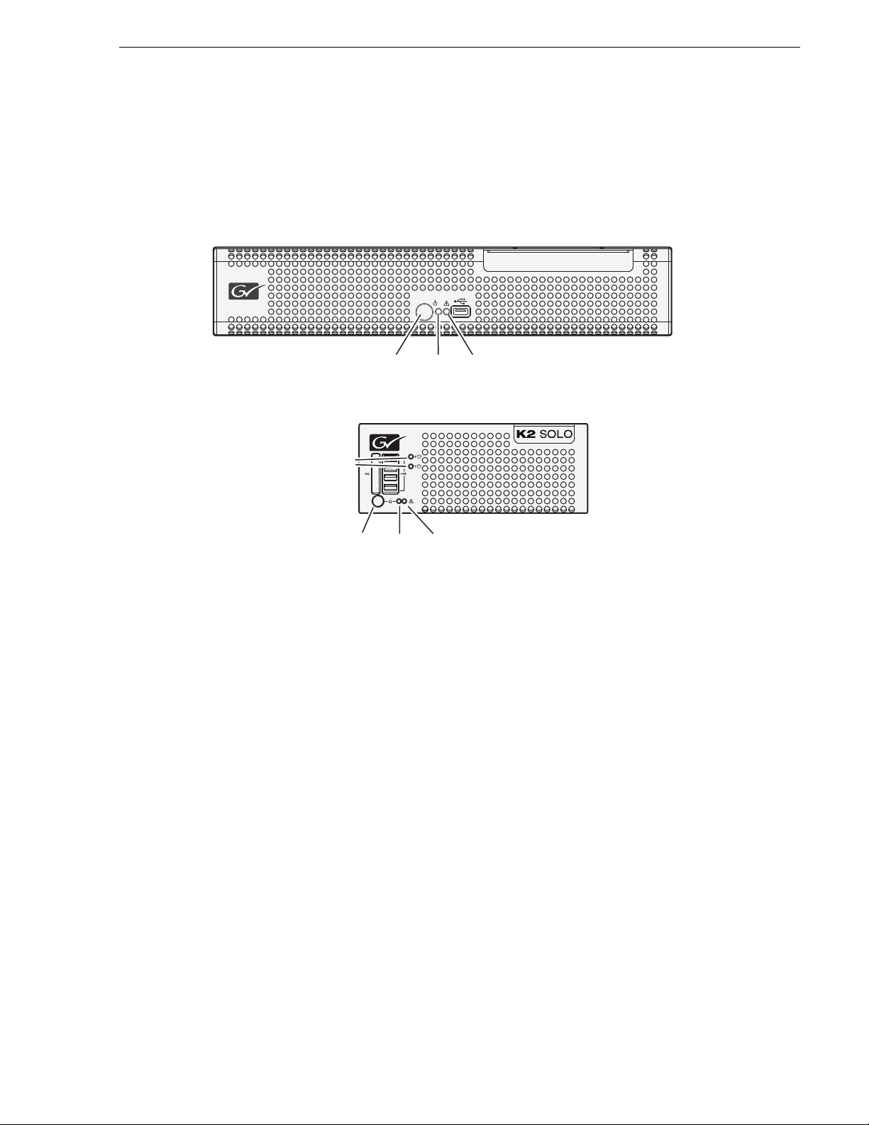
Front panel indicators
LED
switch
LED
D
With the front bezel in place, the indicator LEDs are visible. The LEDs indicate the
status of the machine. For example, when the Service LED is a steady yellow light,
this could signify t hat one of the power cables is unpl ugged. For more i nformation on
indicator LEDs, see the service manual for your K2 product.
Front panel indicators
isk Module
LEDs
Standby
switch
Standby
Power
LED
Power
Service
LED
K2 SUMMIT
Service
PRODUCTION
CLIENT
07 April 2010 K2 System Guide 23
Page 24
Chapter 1 Product Description
C
I/O
SDI OUT1 SDI OUT2
AES AUDIO RS422
LTC I/O
SDI IN1 SDI IN2 SDI IN3
3
1394 100BT/1000BT
3
1394 100BT/1000BT
SDI video in and out supports embedded audio.
P
d
s
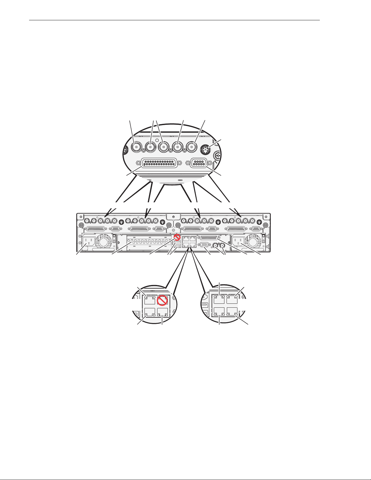
Rear panel view
The following drawings identify the rear panel connectors and components.
K2 Summit Production Client rear panel
SDI in
(connect via optional
multi-connector cable)
AES audio
Channel 1
SDI IN1 SDI OUT1 SDI OUT2
ower
SDI IN2 SDI IN3 SDI IN1 SDI IN2 SDI IN3 SDI IN1 SDI OUT1 SDI OUT2
AES AUDIO RS422
C1
Optional Fibre Channel
card for connection to
direct-connect storage
or shared (SAN) storage
Port 2: FTP/Streaming
Media Connection #1
Stand-alone direct-connect
LTC I/O
OK
!
~AC
or internal storage
Channel Flex
Channel 2 Channel 3 Channel 4
AES AUDIO RS422
IEEE
1394
(Do not
use)
SDI OUT1 SDI OUT2
aa a a, b
SDI out SDI monitor out.
LTC in/out
RS-422
LTC I/O
C2 C3 C4
USB
(keyboard,
mouse)
SDI IN2 SDI IN3 SDI IN1 SDI IN2 SDI IN3
AES AUDIO RS422
USB/1394 100BT/1000BT
VGA REF. LOOP THROUGH
monitor
LTC I/ O
AES AUDIO RS422
GPI
Reference
VGA
Loop Thru
Port 2: Media (iSCSI) A
Media Connection #1
SDI OUT1 SDI OUT2
LTC I/O
OK
!
~AC
GPI
Power
c
Port 3: Media (iSCSI) B
for redundant SAN
Media Connection #2
Shared (SAN)
storage
Port 1: Control
Control Connection #1
a
Supports
Channel Flex Suite,
which requires
AppCenter
Elite license
24 K2 System Guide 07 April 2010
Port 4: Control
dd
(Optional)
Control Connection #2
b
Supports Super Out,
which requires
AppCenter Pro or
Elite license
c
Tri-level sync
not supported
Port 1: Control A
Control Connection #1
d
Port 4: Control B
for redundant SAN
Control Connection #2
d
Control Connections are teame
and share the same IP addres
d
Page 25
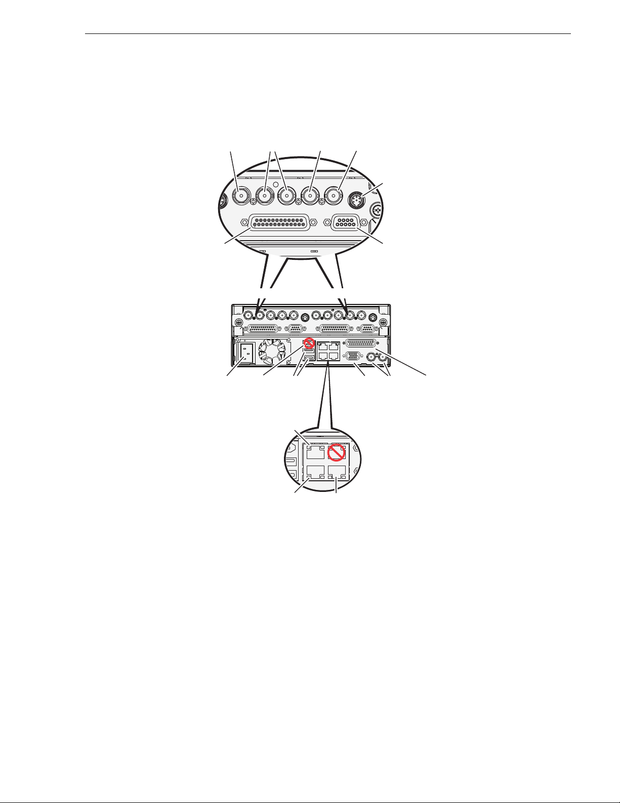
K2 Solo Media Server rear panel
C
I/O
SDI OUT1 SDI OUT2
AES AUDIO RS422
LTC I/O
SDI IN1 SDI IN2 SDI IN3
3
RS-422
SDI in
SDI out SDI monitor out.
(connect via optional
multi-connector cable)
LTC in/out
AES audio
Power
Port 1: Control
Port 2: FTP/Streaming
Control Connection #1
Control Connection #2
Media Connection #1
Port 4: Control
(Optional)
IEEE
1394
(Do not
use)
Reference
Loop Thru
VGA
monitor
USB
(keyboard,
mouse)
GPI
Channel 1 Channel 2
Channel Flex
SDI video in and out supports embedded audio.
Supports
Channel Flex Suite,
which requires
AppCenter
Elite license
a
aa a a, b
Supports Super Out,
which requires
AppCenter Pro or
Elite license
b
Tri-level sync
not supported
c
c
Control Connections are teamed
and share the same IP address
d
d
d
SDI IN1 SDI OUT1 SDI OUT2
SDI IN2 SDI IN3 SDI IN1 SDI IN2 SDI IN3
AES AUDIO RS422
C1
100-240 V-
4-2A,
60-50Hz
LTC I/ O
USB/1394
AES AUDIO RS422
100BT/1000BT
SDI OUT1 SDI OUT2
VGA
GPI
K2 Solo Media Server rear panel
LTC I/ O
C2
REF. LOOP THROUGH
07 April 2010 K2 System Guide 25
Page 26
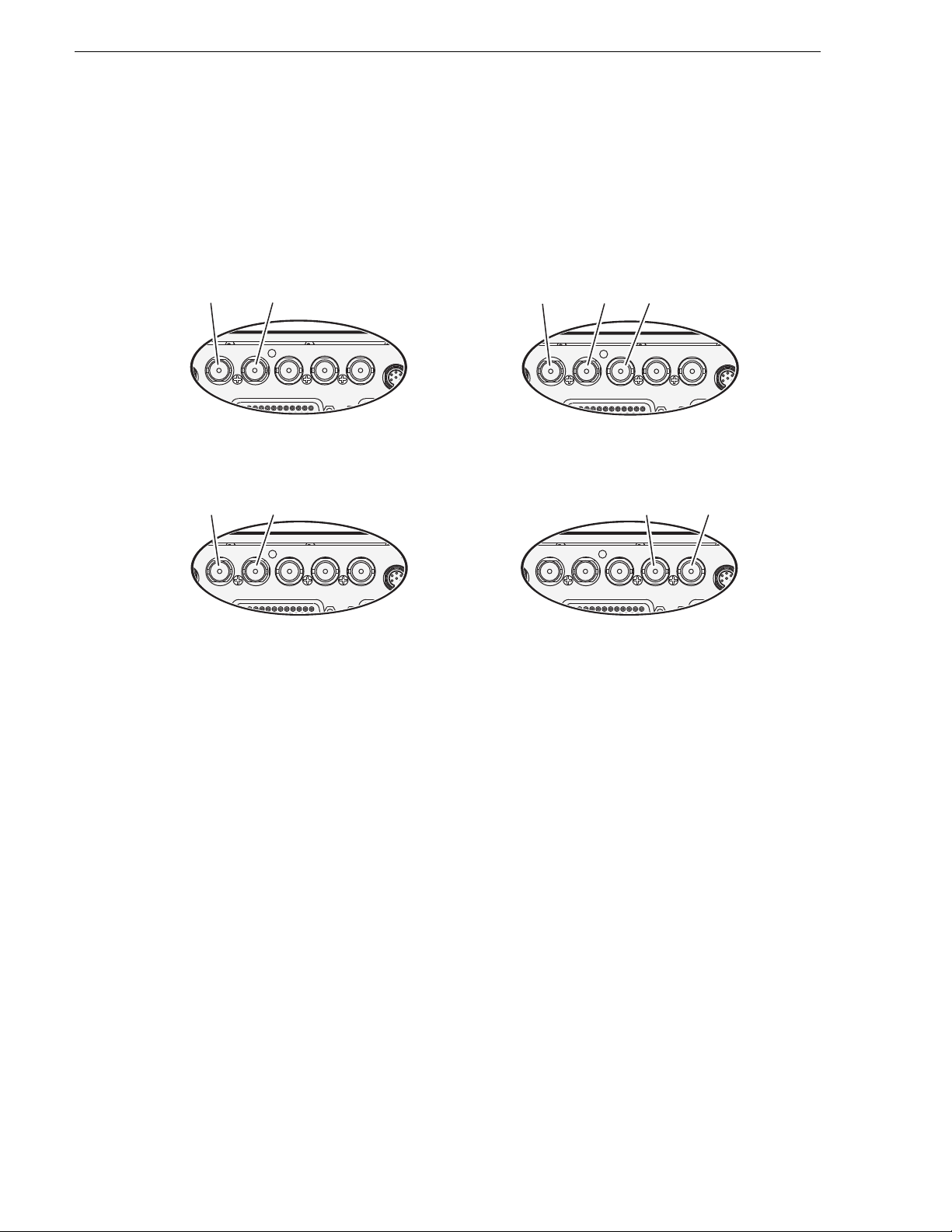
Chapter 1 Product Description
SDI OUT1 SDI OUT2
AES AUDIO RS422
LTC I/O
SDI IN1 SDI IN2 SDI IN3
Super Slo-Mo Recorder
SDI OUT1 SDI OUT2
AES AUDIO RS422
LTC I/O
SDI IN1 SDI IN2 SDI IN3
Multi-Cam Recorder
SDI OUT1 SDI OUT2
AES AUDIO RS422
LTC I/O
SDI IN1 SDI IN2 SDI IN3
V
SDI OUT1 SDI OUT2
AES AUDIO RS422
LTC I/O
SDI IN1 SDI IN2 SDI IN3
ChannelFlex Suite rear panel connections
ChannelFlex Suite features require the AppCenter Elite license. Super Slo-Mo also
requires the HD licens e. When configur ed for these features, channe l connection s are
as follows:
Video 1 Video 2
3D/Video + Key Recorder
ideo or
Left eye
Key or
Right eye
Phase 1 Phase 2 Phase 3
3D/Video + Key Player
Video or
Left eye
Right eye
Refer to the K2 AppCenter User Manual for more informat ion on Cha nne lFlex S uite
features.
Considerations for first startup out of box
When you receive a K2 system from the factory, one or more End User License
Agreements (EULAs) appear on the screen at first startup. Software licensing
agreements require that yo u accept these E ULAs. Whe n you do s o, star t up pro cesses
can proceed. This behavior occurs only at first startup. Subsequent startups do not
exhibit this behavior.
Key or
26 K2 System Guide 07 April 2010
The following are examples of the EULAs that you might see.
On a K2 Media Server, at first startup the following behavior occurs:
• A Windows Server 2003 End User License Agreement (EULA) opens on the
screen.
Page 27

K2 Summit Production Client and K2 Solo Media Server system overview
K2 Summit Production Client and K2 Solo Media
Server system overview
The K2 Summit Production Client and K2 Solo Media Server are purpose-built cl ients
based on COM Express compact computer with dedicated systems to provide the
video disk recorder f unctionality. This secti on explains the major archi tectural blocks.
Application System
The K2 Summit Production Client and K2 Solo Media Server application system
architecture use s the COM Express form factor to provi de functionality similar to that
of standard PC-type computers. The carrier module contains a CPU module, built in
Ethernet, and USB ports. On the K2 Summit Production Client, the carrier module
also includes one PCIe board slot for expansion.
The Application system uses a Windows XP embedded operating system upo n which
all internal storage K2 system applications run for configuration and control of the
unit.
Real Time System
Each channel hosts a complete Real Time system that provides the core video disk
recorder functionality. Primary components are as follows:
• Dedicated processor for media access and processing.
• Codec circuits resp onsibl e for enc oding/ decodin g vid eo and proc essing audio and
timecode, including the media-related input and output connectors.
The Real Time system uses a dedicated operating system. This operating system
manages all the hardware i nvolve d in cont rolling t he flow of video, a udio, ti mecode,
genlock, and GPI in and out of the K2 system.
Media control and processing
The following section e xplains how the Applica tion system and the Real Time s ystem
work together to provide K2 system functionality.
The high processin g r equirements of digita l vi deo can overwhelm the pr ocessor on a
standard d esktop PC, resulting in wait-times that destroy the video’s essentia l
real-time aspect . The K2 s ystem avoids this prob lem by provi ding dedica ted s ystems
that isolate processing needs. The components that work together to provide this
functiona lity are as fo llows:
The
Application system is dedicated to control, configuration, and networking
functions that do not require real-time accuracy. The Application system has the
following components:
• Application softwar e provi des the use r inte rface for opera ting th e K2 system. The
software runs as Windows programs.
• The Media File system manages clips. It includes a database that associates the clip
with its video, au dio, and timecod e files and a dedicated f ile system (sep arate from
the Windows file system) that controls access to the raw data that makes up each
file. Any reading and writing of clips, be it through play and record operations or
through file transfers and media streaming, is managed by the database. The
07 April 2010 K2 System Guide 27
Page 28

Chapter 1 Product Description
database and file system run as Windows programs.
The
Storage system incl udes the media disk drives , control lers , driver s, and ada pters
necessary for access and movement of the data. While the primary data flow is within
the overall control of the Real Time system, some components and their
communication pathways cross over into the Application system. For example, the
media drives appear as the V: drive to the Windows operating system.
Real Time system manages the media flow between the Storage system and the
The
inputs and outputs. The Real Time system has dedicated processors and
time-sensitive mechanisms to serve media processing needs while maintaining
real-time accuracy.
When you control play an d record operati ons from within the Application sys tem you
trigger a chain of events that eventually crosses over into the Real T i me system a nd
results in media ac cess. The f ollowing sequ ence is an ex ample of this type of chai n of
events:
1. A user operates the Player application to play a particular clip. The Player
application asks the Media File system for permissi on to access the clip. The Media
File system grants access. In shared storage models, the Media File system
enforces shared storage policies in order to grant the access. When access is
granted, the Player application initiates play access to the clip.
2. The database identifies the files that make up the clip and the file system instructs
the Storage system to open access to the files.
3. The Storage system finds the raw data and opens the appropriate read access. At
this point both the Application system and the Real Time system are involved.
Windows controls the media drives and controllers, so the Real Time system
makes file requests to Windows and it causes the data to be transferred to buffers
on the Real Time process or. The data i s then avai labl e to the Real Time syst em so
that it can be processed at exactly the right time.
4. The Real Time system processes the media, decompresses it, adjusts it s timing, and
moves it as required to play the clip as specified by the user.
Loop through, E to E, and feeds
Behaviors related to input signals routed to output connectors are described in the
following sections. Also refer to Appendix A, Remote control protocols for
information regarding E to E commands.
Recording synchronous and asynchronous feeds
For best results in all workflows, use synchronous feeds, defined as follows:
• All outputs are locked to the hous e reference
• All inputs are genlocked to the house reference and at zero time
The SD-00 K2 Media Client, the HD-00 K2 Media Client, th e K2 Summit Production
Client and K2 Solo Media Server can record inputs that are asynchronous, with the
following considerations:
• The encoder clock and the audio clock are derived from the input signal, which
enables frame accurate recording of all inputs.
28 K2 System Guide 07 April 2010
Page 29

Loop through, E to E, and feeds
• Outputs are timed to the reference an d if no referen ce is present, the output runs
free.
• If the input video rate does not equal the output video rate (asynchronous) then
video tearing or jumping can occur when input/output synch is critical, such as in
the following:
•K2 TimeDelay
• SD-00 or Summit E-to-E (LoopThru) mode
• HD-00 Loopback
Loop through (K2 Summit Production Client, K2 Solo Media Server, or SD-00 K2 Media Client)
The Player/Recorder application has a “E-to-E (LoopThru) mode” selection on the
Control menu. This mode applies when th e channel is under local AppCe nter con trol
as well as when it is under remote control, for all protocols.
This “E-to-E (LoopThru) mode ” feature al lows you to monitor the video that is being
recorded. The video i s routed ba ck essentia lly untouche d. Any audio or timecode that
is on the input video strea m is stil l ther e on the lo op throug h output . The K2 Summit/
Solo, or SD-00 K2 Media Client, and the loop through videos must be locked to a
video reference for the loop through feature to work properly. This “E-to-E
(LoopThru) mode” feature should not be confused with true E to E, such as that on
the SDA-00 K2 Media Client. True E to E is not s upported on theK2 Summit/So lo or
SD-00 K2 Media Client.
When “E-to-E (LoopThru) mode” is not selected, the channel behaves as follows:
• “PB” is displayed on the channel pane, next to the Timecode Source indicator.
• When no clip is loaded, black plays out.
• When a record operation stops, Recorder becomes Player and the clip remains in
the Player. The clip’s last frame p lays out.
When “E-to-E (LoopThru) mode” is selected, the channel behaves as follows:
• “EE” is displayed on the channel pane, next to the Timecode Source indicator.
• When no clip is loaded, the signal that is currently present at the channel input
plays out.
• When a record operation stops, Recorder stays Recorder and the clip remains in the
Recorder. The signal that is currently present at the channel input plays out.
07 April 2010 K2 System Guide 29
Page 30

Chapter 1 Product Description
Ports used by K2 services
The following ports are use d by th e appli cations and syste m tools o f the K2 family of
products:
Port # Typ e of
connection
20 TCP Can be
21 TCP ftpd.exe FTP data
161 UDP snmp.exe SNMP
162 UDP snmptrap.exe SNMP trap
3389 TCP Remote Desktop Used by SiteConfig .
3811 TCP Grass Valley
18262 TCP GV ProductFrame
18263 UDP ProductFrame
18264 UDP ProductFrame
Service name Description
FTP
mpgsession.exe,
mxfsession.exe,
gxfsession.exe, or
ftpd.exe
Used by 3rd party applications t o communicate
AppService
Configuration Service,
ProductFrame
Discovery Agent
Service
Discovery Agent
Service
Discovery Agent
Service
using AMP protocol
Used by SiteConfig.
GV NetConfig Device Broadcast /Unicast
Protocol. Used by SiteConfig. Sent by
ControlPoint, received by Devices
GV NetConfig Controll er Protocol. Used b y
SiteConfig. Sent by Devices, received by
ControlPoint
49168 HTTP Grass Valley
49169 TCP
49170 HTTP Grass Valley
49171 TCP Grass Valley
49172 HTTP Grass Valley
30 K2 System Guide 07 April 2010
K2 Config
Transfer Queue Service
AppService
Storage Utility Host
K2 System Configuration application connection
between a control point PC and the K2 system
device configured. Both HTTP and TCP
connections are required. Most functions use the
HTTP connection, but a few functions that
require longer time periods use TCP.
Transfer Manager connection betw een source
system and destination system.
AppCenter connection for connection between
control point PC and K2 client/Solo.
Connection for Storage Utility between the
control point PC and the K2 system being
configured.
Page 31

RAID drive numbering
In the K2 Summit Producti on Client, internal RAID dr i ves are numbered as follows .
This numbering is displaye d in Storage Utility. You cann ot see the labeling on the K2
Summit Production Client chassis RAID drive when you remove the fan module.
Disk2 Disk4 Disk7
Disk1 Disk3 Disk6
Disk0 Disk5
Drive numbering Explanation
Disk0 When configured as RAID 1, these two RAID dri ves make up LUN 0.
Disk1
Disk2 When configured as RAID 1, these two RAID dri ves make up LUN 1.
RAID drive numbering
Disk3
Disk4 When configured as RAID 1, these two RAID dri ves make up LUN 2.
Disk5
Disk6 When configured as RAID 1, these two RAID dri ves make up LUN 3.
Disk7
In the K2 Solo Media Serv er, internal RAID drives are numbered as follows:
Disk0
Disk1
NOTE: K2 Solo Media Server drives are always configured as RAID 0.
When drives are configured as RAID 0, each drive is considered its own LUN. As
such, the order of LUNs and drive numbers as displayed in Storage Utility does not
always correlate with the position of drives in the chassis.
07 April 2010 K2 System Guide 31
Page 32

Chapter 1 Product Description
32 K2 System Guide 07 April 2010
Page 33

Chapter 2
Using K2 system tools
Topics in this chapter include the foll owing:
• “Configuration Manager”
• “K2 System Configuration”
• “Storage U tility”
• “NetCentral”
• “Windows Remote Desktop Connection”
• “SiteConfig — a ProductFrame app lication”
Configuration Manager
The Configuration Manager is the primary configuration tool for a K2 Summit
Production Client or K2 Solo Medi a Server. It makes sett ings that apply to th e overall
internal storage K2 system as well as settings that apply to individual channels.
Configuration Manager settings are stored in a database. When the K2 system starts
up it reads the current settings from the database and configures itself accordingly.
When you modify a setting in Configuration Manager you must save the setting in
order to update the data base and reco nfigure t he K2 Summit Productio n Client or K2
Solo Media Server.
You can also save settings out of Configuration Manager into a configuration file,
which is a stand-alone XML fi le . Like wis e, you can load settings into Configuration
Manager from a configurati on file. However, you must use Confi guration Manager as
the means to save the settings to the database before the settings actually take effect.
Configuration files are not linked directly to the database.
You can use confi guration files as a means to back up your s ettings . You can also use
configuration files to save several diffe re n t g roup s of customized settings, each wit h
a unique name, so that you can quickly load settings for specialized applications.
For Configuration Manager procedures, refer to the K2 AppCenter User Manual.
Accessing Configuration Manager
You access Configuration Manager through AppCenter from the local K2 Summit
Production Client, K2 Solo Media Server, or the Control Point PC. To access the
configuration settings, open AppCenter and select
System | Configuration.
Saving and restoring Configuration Manager settings
Settings can be saved as a configuration file. You can save any number of uniquely
named custom configurat ion files. Yo u can load a c onfiguratio n file to rest ore system
settings.
07 April 2010 K2 System Guide 33
Page 34

Chapter 2 Using K2 system tools
To save custom settings:
1. In the Configuration Manager, click the
The Save As dialog opens.
2. Use the up arrow or select folders to navigate to the folder in which you want to
save the configuration file.
3. Enter a name for the configuration file.
Do not name the file DefaultConfig.xml, as this name is re served for the factory
default configurat ion f il e. Ot her wis e, standard Windows 2000 and up file na ming
restrictions apply.
4. Click
Save and Close.
To restore custom settings:
1. If you want to save current settings, you should save them as a configuration file
before continuing.
2. In the Configuration Manager, click the
The Open dialog opens.
3. Use the up arrow or select folders to navigate to the custom configuration file.
4. Select the custom configuration file.
5. Click
Open.
Save button.
Load button.
The custom settings are loaded into Configuration Manager, but they have not been
saved and p ut into effe ct.
6. Click
OK to save and apply settings, and to close the Configuration Manager.
Restoring default Configuration Manager settings
You can res tore factory default settings as follows:
• Restore some individual settings or groups of settings by selecting the
button which appears below the settings in the configuration screen.
• Restore all the s ettings i n Configurat ion Manage r at once to th eir def ault value s as
explained in the following procedure.
To restore all settings at once to their defaul t values:
1. If you want to save current settings you should work through the previous
procedure “Saving and restoring Configuration Manager settings” before
proceeding.
2. In the Configuration Manager dialog, click
The default settings are lo aded into Configuration Manager , but they have not yet
been saved and put into effect.
3. Click
OK to save settings and close Configuration Manager.
Restore.
Default
34 K2 System Guide 07 April 2010
Page 35

K2 System Configuration
The K2 System Configuration application (K2Config) is the primary tool for
configuring the K2 SAN so ftwar e. Once t he devi ces o f the stora ge syst em are cable d
and are communicating on the control network, you can do all the configuration
required to creat e a working K2 SAN usin g the K2 System Conf iguration appl ication.
When you use SiteConfig for network configuration, you can import the SiteConfig
system description f ile into K2Config t o get you started wi th your SAN configu ration.
After your K2 SAN is initially instal led and confi gured, as inst ructed in the
installation and configuration chapters in the K2 SAN Installation and Service
Manual, if you need to reco nfigure the syst em you should d o so using SiteConf ig and
the K2 System Configuration Application. This enforces consistent policy and
sequencing for configuration tasks, which makes the system easier to maintain and
aids in troubleshooting should a problem arise.
The K2 System Configuration application runs on a control p oint PC and accesse s the
devices of the K2 SAN via the control network. You can config ure the devic es of the
K2 SAN as follows:
• K2 client and K2 Media Server — These devices are configured directly by the K2
System Configuration application.
K2 System Configuration
• K2 RAID storage devices — The K2 System Configura tion applica tion launches a
remote instance of Storage Utility, which configures RAID storage devices.
Storage Utility components run on the K2 Media Server and the configuration
actually takes place via the Fibre Channel connection between the K2 Media
Server and the RAID storage device.
• Ethernet switches — The K2 System Configuration application can launch a
switch’s web-based configuration application.
To open the K2 System Configuration application do the following:
1. On the control po int PC open the K2 System Confi guration applic ation shortcut on
the desktop. The K2 System Configuration application log in dialog box opens.
2. Log in using the designated administrator account for configuring K2 SAN
devices. By default this account is as follows:
Username: Administrator
Password: adminK2
3. The K2 System Configuration application opens.
07 April 2010 K2 System Guide 35
Page 36

Chapter 2 Using K2 system tools
W
s
i
hen you select a K2 storage
ystem, device, or subsystem
n the tree view...
If you have one or more K2 SANs currently configured, the K2 System
Configuration application displays the systems in the tree view.
Toolbar buttons are displayed
according to operations available...
And related
information and
configuration
controls appear.
If you have not yet configured a K2 SAN, the K2 System Conf iguration application
opens with the tre e view blank. Ref er to the ins tallation and configura tion chapters
in the K2 SAN Installation and Service Manual to add and configure a new K2
SAN.
You can expand and select nodes in the tree view to view K2 SANs, individual
devices, and config uration settings . When you do so, the K2 Syst em Configuration
application displays information as found in a configuration file, rather than
continuously polli ng device s to get th ei r lates t infor mat ion. The conf ig urati on file
is saved on the V: drive, along with the media files in the shared storage system.
The configuration fi le i s u pdat ed a nd s ave d whenever you change a configuration
using the K2 System Confi gur at ion application. That is why you must always use
the K2 System Configuration a pplication to cha nge settings on the storage syste m,
so the most recently changed configurations will always be stored in the
configuration file and displayed.
Storage Utility
There are two versions of Storage Utility:
• Storage Utility for the K2 SAN.
• Storage Utility for stand-alone K 2 systems
This manual explains Storage Utility for stand-alone K2 clients. Refer to the K2 SAN
Installation and Service Manual to learn about Storage Utility for the K2 SAN.
36 K2 System Guide 07 April 2010
Page 37

NOTE: For shared storage, ru n Storage Utili ty only via the K2 System Configu ration
!
application.
The Storage Utility is your primary access to the media file system, the media
database, and the media di sks of the K2 Summit Product ion Clien t or K2 Solo Media
Server for configuration, maintenance, and repair. It is launched from AppCenter
workstation.
NOTE: Do not use the MegaRAID utility on a K2 system. This utility is for use by
qualified Grass Valle y Service per sonnel only. Whe n this ut ility is opene d it scans th e
SCSI bus and interferes with record and play operations.
NetCentral
NetCentral is Grass Valley’s monitoring application. The NetCentral server
component runs on a NetCentr al ser ver PC, whi ch could also be a K2 syste m contro l
point PC. Devices report st atus, primari ly via Simple Network Ma nagement Protocol
(SNMP), to NetCentral on the NetCen tral server PC.
NetCentral
CAUTION: Use the Storage Utility only as directed by a documented
procedure or by Grass Valley Support. If used i mp rope rl y, the Storage
Utility can render your K2 Summit Production Client inoperable or
result in th e loss of all your media.
Refer to NetCentral manuals get the NetCentral system installed and operating. You
must instal l a NetCentral device provider on the NetCen tral server PC for each type
of device you are monitoring.
NOTE: NetCentral is optional if you are using a stand-alone K2 system only.
NetCentral is required if you are using a K2 SAN.
Windows Remote Desktop Connection
You can connect to a K2 client, K2 Solo Media Server, or a K2 Media Serve r remotely
using the Microsoft Windows Remote Desktop Connection application. Do not use
the Remote Desktop Connection to access t he PC running t he Control Poi nt software
or to access the AppCenter application; results may be unreliable. Also, take care
when accessing an online K2 system on which media access is underway. The
additional load on network and system resources could cause unpredictable results.
You can use either the name or the IP address to access the K2 system.
NOTE: Before you can use the Remot e Desktop Connection, you need network access
and permissions to connect to the K2 system.
To access the Remote Desktop Connection, follow these steps:
1. Click the
—or—
Start button on the Windows task bar
Press the Windows key on the keyboard.
2. Select
07 April 2010 K2 System Guide 37
Programs | Accessories | Communications | Remote Desktop Conn ection. The
Page 38

Chapter 2 Using K2 system tools
Remote Desktop dialog box displays.
3. Enter the name or IP address of the K2 system and click the
Alternately, you can click the down arrow of the text box and browse for the K2
system or select a previously entered computer.
Connect button.
SiteConfig — a ProductFrame application
ProductFrame is an integr ated platform of tools and product distributi on processes for
system installation and configuration. SiteConfig is a ProductFrame application and
it is the recommended tool for network configuration and software deployment.
You can use SiteConfig as a stand-alone tool for planning and system design, even
before you have any devices installed or cabled. You can define networks, IP
addresses, hostnames, int erfaces, and other network parameters. You can add devices,
group devices, and modify device roles in the system.
As you install and commission systems, SiteConfig runs on the control point PC. It
discovers devices, configures their network settings, and manages host files.
SiteConfig also manages software installations and upgrades and provides a unified
software package for deployment across multi-product systems.
You should use SiteConfig for network configuration and software deployment at
installation and throughout the life of the system in your factility. This enforces
consistent policy and a llows Site Config t o cap ture change s, which make s the sys tem
easier to maintain and aids in troubleshooting should a problem arise.
To open SiteConfig, do the following:
1. On the control point PC open the SiteConfig shortcut on the desktop.
The SiteConfig application opens.
38 K2 System Guide 07 April 2010
Page 39

SiteConfig — a ProductFrame application
Select a
module...
And a tree
view tab...
Then select an item
in the tree view...
To display list
view details...
SiteConfig displays information from a system description file, which is an XML
file.
SiteConfig has different modules that correspond to a system’s life-cycle phases,
such as network configuration and software deployment. You can expand nodes
and select element s in the t ree view and the list vi ew to view an d modify networ ks,
systems, individual devices, software deployment, and configuration settings.
07 April 2010 K2 System Guide 39
Page 40

Chapter 2 Using K2 system tools
40 K2 System Guide 07 April 2010
Page 41

Chapter 3
System connections and configuration
This chapter contains the following topics:
• “About networks”
• “Network connections”
• “Network configuration”
• “Using FTP for file transfer”
• “Using the HotBin service”
• “Using the Pathfire capture service”
• “Using the DG capture service”
• “Using the XML Import capture service”
• “Licensing K2 capture service software”
• “Pinnacle support”
• “Compressed VBI import”
• “Quicktime and Final Cut Pro support”
• “Connecting RS-422”
• “Connecting GPI”
Also refer to Chapter 9, K2 Summit Transmission Server Package for information
unique to that product.
07 April 2010 K2 System Guide 41
Page 42

Chapter 3 System connections and configuration
About networks
The following section describe networks as they apply to K2 systems. Also refer to
the K2 SAN In stallation and Configuration Guide for more detailed information about
K2 SAN networking.
Control network description
The control network is for communication betwee n devices and components. It does
not have real-time medi a traffic or strea ming/FTP media t raffic. The control ne twork
must be on a differen t subnet t han the s treaming/FTP ne twork and t he Media (iSCSI)
network. Static IP addres ses with name reso lution via hos t files are r ecommended for
the control network.
Streaming/FTP network description
The streaming/FTP network is for media transfers and FTP traffic. It must be on a
different subnet than the control network and the Media (iSCSI) network. Static IP
addresses with name resol ution via host files are recommended for the streaming /FTP
network. Hostnames of network adapters that are dedicated to the streaming/FTP
network must be aliased in the host file with the _heo suffix. This directs the
streaming traffic to the correct port.
Media (iSCSI) network description
The media network is exclusively for real-time iSCSI traffic on a K2 SAN. It must be
on a different subnet than the control network and the streaming/FTP network.
Furthermore, its traffic is kept physically separate from that of other networks. This
separation is provided by dedicated ports, cables, and by a dedicated VLAN on the
Ethernet switch or by sepa rate switches. Static IP addresses are required for the media
network. Name resolution is not necessary, so media network IP addresses are not
required in host files.
42 K2 System Guide 07 April 2010
Page 43

Network connections
Use the information in this section as appropriate to connect the Gigabit (1GBaseT)
Ethernet network for your application:
• “Cable requirements”
• “About network ports”
• “Making network connections”
Cable requirements
For making Ethernet connections, cabling must meet the following requirements:
• Use CAT5e or CAT6 cables. The maximum cable length is 50 meters for CAT5e
and 100 meters for CAT6.
About network ports
When you receive a K2 Summit Produc tion Cli ent or K2 Solo Media Serv er from t he
factory, it has a specific network confi guration, i ncluding a l oopback adapt er and two
of the four Gigabit Ethernet ports configured as a teamed pair. The Gigabit Ethernet
ports, as vie wed when looking at the rear panel, are represented in the follow ing
illustration.
Network connections
Media
Connection #1
iSCSI:
SAN
storage
FTP/Streaming:
23
Internal and
direct-connect
storage
Control:
Internal,
directconnect,
and SAN
storage
1
Control Team: Same for internal, directconnect, and SAN storage.
Control
Connection #1
The K2 Solo Media Server is not supported for SAN (shared storage) connection.
Media
Connection #2
iSCSI:
Redundant
SAN
storage
Control:
Redundant
SAN
storage
4
Control
Connection #2
07 April 2010 K2 System Guide 43
Page 44

Chapter 3 System connections and configuration
Making network connections
Connect network ports as appropriate for the K2 Summit Production Client or K2
Solo Media Server storage option, as follows:
Stand-alone storage K2 Summit/Solo network connections
SDI IN1 SDI OUT1 SDI OUT2
SDI IN2 SDI IN3 SDI IN1 SDI IN2 SDI IN3
LTC I/O
SDI OUT1 SDI OUT2
LTC I/O
FTP/streaming
network
Control network Optional connection for
AES AUDIO RS422
Port2Port
3
Port
Port
1
4
100BT/1000BT
redundant control network
GPI
VGA REF. LOOP THROUGH
AES AUDIO RS422
C4
OK
!
~AC
On a K2 Solo Media Server, an internal storage K2 Sum mit Production Client, or a
direct-connect stora ge K2 Summit Product io n Client , conne ct the contr ol net w ork to
port 1, which is t he f ir st po rt of the control tea m. I f you have a FTP/streaming network,
it is connected to por t 2. Port 3 is not used. In most cases port 4, which i s the second por t
of the control team, is not used , although it is availabl e to provide additiona l redundancy
for the control network connect io n.
Basic shared storage (SAN) K2 Summit Production Client network connections
SDI IN1 SDI OUT1 SDI OUT2
Media (iSCSI)
network
SDI IN2 SDI IN3 SDI IN1 SDI IN2 SDI IN3
AES AUDIO RS422
Port2Port
3
Port
Port
1
4
100BT/1000BT
VGA REF. LOOP THROUGH
LTC I/O
GPI
AES AUDIO RS422
SDI OUT1 SDI OUT2
LTC I/O
C4
OK
!
~AC
Control network Optional connection for
redundant control network
On a non-redundant shared st orage (SAN) K2 Summit Product ion Client, connect the
control network to port 1, which is the first port of the control team. Port 2 must be
connected to th e media (iSCSI) networ k. Port 3 is not used. Port 4, whi ch is the secon d
port of the control team, is n ot used exc ept as f ollows: Por t 4 may be u sed only if y ou
extend your control network to provide the same redundancy as that of a redundant
K2 SAN.
Refer to the K2 SAN Installation and Service Manual for more information.
44 K2 System Guide 07 April 2010
Page 45

Network configuration
Redundant shared storage (SAN) K2 Summit Production Client network connections
SDI IN1 SDI OUT1 SDI OUT2
SDI IN2 SDI IN3 SDI IN1 SDI IN2 SDI IN3
LTC I/O
SDI OUT1 SDI OUT2
LTC I/O
Media (iSCSI)
network A
Control network A Control network B
AES AUDIO RS422
Port2Port
3
Port
Port
1
4
100BT/1000BT
Media (iSCSI)
network B
VGA REF. LOOP THROUGH
On a redundant shared storage (SAN) K2 Summit Production Client, you must
connect both ports of the co ntrol team. Connect control networ k connection A to port
1 and control network connection B to port 4. You must also connect both media
ports. Connect port 2 to the A media network and port 3 to the B medi a network. The
media ports must not be teamed, as doing so interferes with failover functionality.
Refer to the K2 SAN Installation and Service Manual for more information.
Network configuration
This section contains instructions for configuring network connections as follows:
• “About network functionality”
• “About modifying or restoring network settings”
AES AUDIO RS422
C4
OK
GPI
!
~AC
• “Configure network settings for a stand-alone K2 systems”
• “Streaming video between K2 systems”
About network functionality
K2 networks support the following:
• Remote control and configuration of the internal storage K2 system using
AppCenter from a Control Point PC.
• Remote control of the internal storage K2 system using devices and applications
software developed for the K2 system that use industry standard remote control
protocols over Ethernet.
• Stream media transfers between K2 systems and other supported Grass Valley
systems. Streaming t ransfers al low loading and playing a clip before t he transfe r is
complete.
• Standard data network capability.
• General networking tasks such as file sharing and mapping network drives.
07 April 2010 K2 System Guide 45
Page 46

Chapter 3 System connections and configuration
!
The procedures in this section guide you to relevant settings, but do not instruct you
on the specific settings required for your network. It is assumed that you understand
Ethernet networks in general and your particular network needs and that you can
apply that understanding to make the required settings using standard Windows
procedures. If you need help with these procedures, contact your network
administrator.
Refer to the K2 SAN Installation and Service Manual for net work configuration
procedures for shared storage K2 clients.
About modifying or restoring network settings
Before configuring network settings, consider the following:
• Write filter — The K2 system has a wr ite filter tha t must be disabled b efore making
a network configuration change. Refer to “About the write filter” on page 155.
• Loopback adapter — When you rece ive a K2 Summit Production Clie nt, a K2 Solo
Media Server, or a K2 Media Client from the factory, it has a loopback adapter
installed. The loopback adapter allows the media file system to continue operating
if an Ethernet cable is disconnected. Do not modify the loopback adapter. If you
need to restor e the loopb ack adapt er, r efer to the Servi ce Manual for you mod el of
K2 client.
The loopback IP address i s 192.168.200.200. Keep that IP a ddress reserved on your
network. Don’t assign it to any other device. (If this causes conflicts with your
existing network, consult your Grass Valley representative.)
• Hostname changes — If you change the host name, remote AppCenter and other
systems could have difficulty connecting. On a shared storage K2 client, Grass
Valley strongly recommends that you do not change the host name or IP address
unless following the doc umented procedur e. For more information, re fer to the K2
SAN Installation and Service Manual.
• Restoring fact ory default networ k settings — Sever al settings are conf igured at the
factory and should never be modified. If you suspect settings have been changed,
you should reimage the K2 system to restore settings. Refer to the K2 Summit
Product Client Service Manual for recovery image and network configuration
procedures.
Configure network settings for a stand-alone K2 systems
CAUTION: The K2 system is not a general purpose Windows
workstation. The Windows configuration on the K2 system has been
specifically set for use as a real-time device. To avoid partial or total
system failure, do not modify any operating system settings unless
approved by Grass Valley, including but not limited to the following:
— Do not use the User Manager
— Do not use t he Disk Administrator
— Do not load any third party software
— Do not install Windows updates
46 K2 System Guide 07 April 2010
Page 47

Configure network settings for a stand-alone K2 systems
!
The internal storage internal storage K2 system and the direct-connect K2 Summit
Production Client ship from the factory DHCP configured. If your control network
has DHCP/DNS and you are satisfied to use the factory default host name (which is
the serial number), then no local configuration of the control connection is required.
If the Windows network set tings for t he stan d-alo ne inte rn al sto rage K2 s ystem nee d
to be configured , you must have Wind ows administrato r security pr ivileges on t he K2
system.
To configure network settings on a stand-alone internal storage K2 system, do the
following:
1. If you have not already done so, disable the write filter. Refer to “Disabling the
write filter” on page 156.
2. Access the Windows desktop on the K2 system. You can do this locally with a
connected keyboard, mouse, and monitor or remotely via the Windows Remote
Desktop Connection.
3. Open the Network Connections dialog box:
• In the Windows Classic view, select
Start | Settings | Network Connections
• In the Windows XP view, select Start | Control Panel | Network Connections
4. Continue with standard Windows procedures to configure the TCP/IP protocol
properties. You can set up the network using DHCP, DNS, WINS, or other
standard networking mechanisms.
NOTE: On smal l networ ks or n etworks wi th cert ain sec urity po licies a DHCP server
or domain name server (DNS) might not be available. In this case you can set up a
static IP address and create a host file on each K2 system.
5. Configure the control con nection on th e stand-al one intern al storage K2 system as
follows:
• Configure the network connection with the following name:
Control Team
The control team is GigE ports 1 (Control Connection #1) and 4 (Control
Connection #2) on the rear panel.
CAUTION: Under no circumstances should you modify the loopback
adapter. The loopback IP address is 192.168.200.200. Keep that IP
address reserved on your network. Don’t assign it to any other device.
If this causes conflicts with your existing network, consult your Grass
Valley representativ e.
6. Configure the FTP/streaming connection (if needed) on the stand-alone internal
storage K2 system.
This connection must have an IP address that is on a different subnet from the
control connection. There are spec ial name resolution requi rements for the FTP/
streaming network.
Configure as follows:
• Configure the network connection with the following name:
07 April 2010 K2 System Guide 47
Page 48

Chapter 3 System connections and configuration
Media Connection #1
This is GigE port 2 on the rear panel.
7. If prompted, shutdown and restart Windows.
8. If you are g oing t o FTP/st ream vid eo b etween K2 syste ms, proce ed to “Streaming
video between K2 systems”; otherwise, the K2 system is ready for standard data
networking tasks.
9. Enable the wri te filter. Ref er to “Enabling the write filter” on page 156.
Streaming video between K2 systems
It is required that FTP/streaming traffic be on a separate subnet from control traffic
and, in the case of a K2 SAN with shared storage K2 clients, separate from media
(iSCSI) traffic. To reserve bandwidth and keep FTP/streaming traffic routed to
dedicated ports, IP addresses for FTP/streaming ports must have double name
resolution such tha t hostnames are a ppended with the “_he 0” suffix. You can use host
tables or another mechanism, such as DNS, to provide the name resolution. This
directs the streaming traffic to the correct port.
In most K2 systems, network name resolution is provided by host tables, which are
found in hosts files. The following procedure describes how to set up hosts tables to
provide name resoluti on for both the control n etwork and the FTP/str eaming network.
If you are using other mechanisms for name resolution, use the host table examples
here to guide you. For shared storage K2 clients, also refer to the K2 SAN Installation
and Service Manual for a discussion of host tables.
Setting up the K2 system for FTP/streaming transfer has the following network
requirements:
• For stand-alone internal storage K2 systems, the K2 machine is the source/
destination for FTP/s tr eami ng t ra nsf er s. FTP/ st re aming traffic uses the FTP GigE
port (Media Connection #1) on the K2 client.
• For K2 Summit Production Clients or K2 Media Clients with shared storage on a
K2 SAN, a K2 Media Server is the source/dest ination for FTP/ streaming tra nsfers.
FTP/streaming traffi c uses the FTP GigE port on the K2 Media Server. No transfers
go to/from the shared storage K2 client directly.
• Some kind of name re solution process must be followed. You must either referenc e
host names through hosts files located on each networked device or edit the DNS
entries. To edit the DNS entries, see your network administrator. To set up host
files, see “Set up hosts files” on page 48.
• The host name of all peer K2 systems and Profile XP systems must be added to a
Remote host registry using the K2 AppCenter Configuration Manager.
• To import to or export fr om a K2 system, both the source and destination must be
in the same d omain.
Set up hosts files
Set up a hos t s file locat ed in c:\WINDOWS\system32\drivers\etc\hosts on each K2
system. If you include t he names and addresse s of all the systems on th e network, then
you can copy this information to all the machines instead of entering it in the hosts
file on each m achine.
48 K2 System Guide 07 April 2010
Page 49

Streaming video between K2 systems
To provide the required name resol ution for the FTP /str eaming net work, in the hos ts
file each system that is a transfer source/destin ation has its host name listed twice:
once for the control network and once for the FTP/st reaming networ k. The host name
for the streaming network has the extension “_he0” after the name. The K2 systems
use this information to keep the FTP/streaming traffic separate from the control
traffic.
For FTP transfers to/f rom a K2 SAN, transfers go to/ from K2 Media Servers that have
the role of FTP server. No transfers go directly to/from the shared storage K2 clients
that are on the K2 SAN. So in the hosts file, you must add the “he_0” extension to a
K2 Media Server hostname and ass oci at e th at hostname with the K2 Media Server’ s
FTP/streaming network IP address.
To see an example, refer to the “Sample K2 client configuration and hosts file” on
page 50. Otherwise, proceed with the following steps to set up your hosts file.
On each K2 system, set up the hosts file as follows:
1. If you have not already done so, disable the write filter. Refer to “Disabling the
write filter” on page 156.
2. Open the following file using Notepad or some other text editor.
c:\WINDOWS\system32\drivers\etc\hosts
3. Enter text in two lines for each K2 syste m that is a tran sfer source/destination.
a. Type the IP address for the contro l network, then us e the TAB key or Sp ace bar
to insert a few spaces.
b. Type the machine name, such as
K2-Client. This sets up the ho st file for res olving
the machine name on the contro l network. The machine name must no t have any
spaces in it.
c. On the next line, type the IP addr ess for the FTP/streamin g network, then use t he
TAB key or Space bar to insert a few spaces.
d. Type the machine name followed by the characters “_he0”. Be sure to use the
zero character, not the letter ‘o’. Refer to the following example:
00.16.42.10 K2-Client
00.0.0.10 K2-Client_he0
4. For syst ems that are n ot a tr an sfer s ource/ desti nati on, t he sec ond li ne (for the FTP /
streaming network) is not required.
5. If there ar e UIM systems on the FTP/streaming n etwork, make sure you f ollow the
UIM naming conventions. Refer to the UIM Instruction Manual.
6. Once you have added the host names for the all the systems on the networks for
which the host file provides name resolution, save the fi le an d exit the text editor.
7. Copy the hosts file onto all the other machines to save you editing it again.
Remember to disable the write filter on all K2 Summit Production Clients.
8. Enable the wri te filter. Ref er to “Enabling the write filter” on page 156.
9. Proceed to “Add host names to AppCenter to enable streaming”.
07 April 2010 K2 System Guide 49
Page 50

Chapter 3 System connections and configuration
K2-Client
(internal storage)
Stand-alone
NewsEdit1
(not shared storage)
SAN_XP1
SAN_UIM1
K2-Client-2
(shared storage)
K2-Media Server-1
Control Point PC
10.0.0.22
Other 3rd party devices
Command/Control network
FTP/Streaming network
10.16.42.10
10.0.0.10
10.16.42.102
10.16.42.60
10.0.0.60
Note: The two media GigE ports are not used for
FTP/streaming. They are used for media (iSCSI)
networks only
10.16.42.22
10.16.42.31
10.16.42.32
10.0.0.32
10.16.42.23
K2-Client-1
(shared storage)
10.16.42.101
Sample K2 client configuration and hosts file
The following diagram illustrates one possible configuration setup, including a K2
system with stand-alone storage, K2 clients with shared (SAN) storage, and other
Grass Valley systems.
The following example shows the contents of a default Windows hosts file with
new lines added that matc h the IP addresse s and host names in the pre vious sample
diagram.
All lines beginning with a # are comments and can be ignored or deleted.
# This is a sample HOSTS file used by Microsoft TCP/IP for Windows.
#
# For example:
# 102.54.94.97 rhino.acme.com # source server
# 38.25.63.10 x.acme.com # x client host
127.0.0.1localhost
10.16.42.10K2-Client
10.0.0.10K2-Client_he0
50 K2 System Guide 07 April 2010
Page 51

10.16.42.101K2-Client-1
10.16.42.102K2-Client-2
10.16.42.22K2-MediaServer-1
10.0.0.22K2-MediaServer-1_he0
10.16.42.23ControlPointPC
10.16.42.60NewsEdit1
10.0.0.60NewsEdit1_he0
10.16.42.31SAN_XP1
10.0.0.32SAN_XP1_he0 SAN_UIM1_he0
10.16.42.32SAN_UIM1
Add host names to AppCenter to enable streaming
Streaming video between K2 systems
In K2 AppCenter, you must add the host na mes of all peer K2 systems on the network
that support streami ng t ra nsf er s. Add ing host names is required to al l ow sel ec ti on of
networked K2 systems in the AppCenter user interface and to provide a successful
network connection fo r str eaming. The host name s added appear in t he “Impor t” an d
“Send to” dialog boxes.
NOTE: By default, the K2 system host name is the same as the Windows computer
name. To determine the K2 sys tem computer name, rig ht-click K2 Client or K2 Media
Server (My Computer) on the Windows desktop, then properties. Select the Network
Identification tab and look for the “Full computer name”.
To add network host names:
1. Open AppCenter for the K2 client.
2. In the AppCenter toolbar, select
3. Select the
Remote tab.
System, then choose Configuration.
The Remote Settings dialog box displays, showing any network host names that
have been added.
4. Select
Add, to open the Add Host dialog box, then do the following:
a. Select the Host name field, then enter the computer name of a peer K2 system.
Make sure to enter the exa ct computer name. Any differences wil l result in being
unable to con nect to the K2 system.
07 April 2010 K2 System Guide 51
Page 52

Chapter 3 System connections and configuration
b. If you are using VDCP remote pr otocol t o perform v ideo networ k transfer s, use
the following steps to a dd a uniqu e Control ler I D for eac h host. Ot herwise , you
can ignore this step and proceed to the next step.
- Select controller id fiel d.
- Enter the controller ID of the K2 system, then select
between 1 and 255 that is not assigned to any other K2 system.
c. Select
5. Repeat the previous step for the remaining K2 systems.
6. In the Configuration dialog box, select
Once the host names a re added, the K2 sys tem is ready for streaming operation . For
information on transfer compatibility and supported formats, refer to Appendix B,
Specifications. For procedures on transferring media, refer to the K2 AppCenter
User Manual.
NOTE: If you have trouble, tr y using the ping utility in the Windows c ommand prompt
using either the IP address or host name. Troubleshoot as needed. Also, refer to the
Service Manual for your K2 system for troubleshooting procedures.
OK in the Add Host dialog box.
Using FTP for file transfer
This section includes the following topics:
“About the K2 FTP interface”
“Limitations with complex media types”
“Transferring between different types of systems”
OK. Use a number
OK to save settings.
“Transfer mechanisms ”
“FTP access and configuration”
“FTP access by automation”
“FTP security”
“FTP internationalization”
“FTP access by Internet Explorer”
“Using FTP on a K2 Nearline SAN”
52 K2 System Guide 07 April 2010
Page 53

About the K2 FTP interface
An application writer may cho ose to initiate media fil e transfers via FTP. The K2 FTP
interface has a GXF f older and an MXF folder. Use th e appropriat e folder, de pending
on if you are transferring GXF or MXF. Refer to “FTP access by Internet Explorer”
on page 56 for examples.
The K2 FTP server runs on K2 Media Ser ver that h as the rol e of FTP server . While it
also runs on the K2 Solo Media Server, stand-alone storage K2 Summit Production
Clients and K 2 Media Clients, it is important to understand that it does not run on
shared storage K2 clients. When you FTP files to/from a K2 SAN, you use the FTP
server on the K2 Media S erver, not on the K2 clie nt that accesses the shared storage
on the K2 SAN.
If clips are created by record or streaming on a K2 file system such th at media fil es
have holes/gaps, i.e. unallocated disk blocks, in them, then that clip represents a
corrupt movie that needs to be re-acquire d. The K2 system handles co rrupt movies of
this type on a best-effort basis. There is no guarantee that all available media,
especially media around the edges of the holes/gaps, is streamed.
You can also apply K2 security features to FTP access. Refer to “Configuring K2
security” on page 158.
About the K2 FTP interface
NOTE: When using FTP in a shared storage environment, ensure that all FTP
communication takes place on the FTP/streaming network, and not on the Control
network.
Limitations with complex media types
• Depending on the syste m software ver sions of s ource and des tination dev ices, it i s
possible that lists or programs made from lists that contain movies with mixed
video compression types or mixe d audio typ es cann ot str eam to othe r devi ces, nor
can they be exported to a file. Refer to release notes for the specific software
versions for details.
• MXF OP1A supports transf er of simple media t ypes only, which a re a subset of the
K2 encode/decode/metadata capabilities. For example, MXF OP1A does not
support the transfe r of compl ex clips , suc h as a su bclip tha t spans two med ia file s.
Do not attem pt MXF OP1A transfers of complex clips.
Transferring between different types of systems
While GXF transfer of media with mixed format (such as an agile playlist) is
supported between K2 sy stems, it might not be suppor ted betwee n a K2 syst em and a
non-K2 system, dependi ng on system softwa re versions. Refer to the release notes for
the software version.
If using remote control protocols to initiate transfers, refer to Appendix A, Remote
control protocols.
Also refer to “Specifications” on page 189.
Transfer mechanisms
You can move material between systems using the following mechanisms, each of
which offers a different set of features:
07 April 2010 K2 System Guide 53
Page 54

Chapter 3 System connections and configuration
• Manual mechanis ms — These are t he AppCenter tr ansfer feat ures. Refer t o the K2
AppCenter User Manual for AppCenter instructions. When transferring b etween
K2 systems you can browse and select files for transfer. When transferring between
K2 systems and other types of systems, one or more of the following might be
required, depending on software versions. Refer to release n otes for the version
information:
- Specify the IP address, path, and file name to initiate a transfer.
- Add the remote host in Configuration Manager before the transfer.
- Enter machine names in compliance with UIM naming conventions.
• Automatic mechanisms, including the following:
• K2 FTP interface — This interface supports transfers via third party FTP
applications. For example, you can use Internet Explorer to transfer files
between a PC and the FTP interface on a stand-alone K2 Summit Production
Client or a K2 Media Server on the same network. For more inf or mati on, re fe r
to “FTP access by automation” on page 54.
• Remote control protocols — Industry standard remote control automation
applications can ini tiate transfers. The p rotocol command must be sent to the K2
client. This applie s to both stand-alone a nd shared storage K2 syst ems. For more
information, refer to Appendix A, Remote control protocols.
FTP access and configuration
For basic LAN access, the following Grass Valley products can connect as an FTP
client to the K2 FTP server with no special configuration required:
• K2 Summit Production Client
• K2 Media Client
• K2 Solo Media Server
• UIM-conne cted Profile XP Media Platform
For WAN access, contact your Grass Valley representative for assistance.
If the FTP client is not one of these Grass Valley products, contact the product’s
supplier or your network system administrator for assistance with configuring TCP
window scaling. Any computer that connects as an FTP client to the K2 FTP server
must have TCP window scaling enabled. Refer to http://support.microsoft.com/kb/
q224829/ for more information on this feature. Never set Tcp1323Opts without
setting TcpWindowSize. Also, Windows NT 4.0 does not support TCP window
scaling, but will still communi cate with Grass Valley products in a LAN environment.
FTP access by automation
Using FTP, third parties can initiate transfers between two K2 systems or between a
K2 system and another FTP server. Transfer s of this type are known as “passive” FTP
transfers, or “server to server” transf ers.
54 K2 System Guide 07 April 2010
Page 55

If you are managing transfers with this scheme from a Windows operating system
computer, you should disable the Windows firewall on that computer. Otherwise,
FTP transfers can fail be cause t he Wi ndows fi rewall detec ts FTP co mmands a nd can
switch the IP addresses in the commands.
NOTE: You should dis abl e t he Wi ndows fi re wall on non-K2 systems issuing p assive
FTP transfer commands.
FTP security
Refer to “FTP and media access security” on page 163.
FTP internationalization
The K2 FTP interface supports clip and bin names in non-English locales
(international languages) as follows:
• Non-ASCII localized characters represented as UTF-8 characters.
• All FTP client/server commands are in ASCII.
• The named movie asset is Unicode 16-bit characters
FTP security
• The K2 FTP client converts between Unicode and UTF-8 strings explicitly.
Also refer to “Internationalization” on page 214.
The Microsoft FTP client does not convert from a Unicode string to a UTF-8 string.
Instead, it passes the Unicode string to the FTP server directly, which can cause
errors. To avoid these errors, in the FTP command, every reference to the clip path
must be in UTF-8.
A specific language setting is required on the computer that hosts the K2 FTP
interface. This requirement applies to a K2 Media Server, K2 Solo Media Server, and
a stand-alone K2 client, as they all host the K2 FTP interface.
To make this language setting, do the following:
1. If you have not already done so, disable the write filter. Refer to “Disabling the
write filter” on page 156.
2. Open the
Regional and Language Options control panel.
07 April 2010 K2 System Guide 55
Page 56

Chapter 3 System connections and configuration
3. On the Advanced tab for the “Language for non-Uni code progr ams” sett ing, selec t
English (United States).
4. Click
Apply and OK, and when prompted restart t he computer to put the c hange into
effect.
5. Enable the wri te filter. Ref er to “Enabling the write filter” on page 156.
FTP access by Internet Explorer
You can use Internet Explorer to transfer files via FTP between a PC and the FTP
interface on a stand-alone K2 system or a K2 Media Server, so long as both source
and destination machines are on the same network.
While the K2 FTP interface supports local languages, some international characters
are not displayed corr ectly in Internet Explore r. Use only English language cha racters
with Internet Explorer.
To access FTP using Interne t Explorer, use the following syntax i n the Addr ess fie ld:
ftp://<username:password@hostname>. The username/password can be
any account set up o n t he machine hosting the FTP interface. Also r ef er t o “FTP an d
media access security” on page 163 for information about accounts and FTP access.
The hostname can be the name of a stand-alone K2 client or it can be the name of a
K2 Media Server. (You cannot make a FTP connection to a K2 client with shared
storage or to a K2 Control Point PC.)
Once you have logged in, the two virtual directories are displayed.
56 K2 System Guide 07 April 2010
Page 57

FTP access by Internet Explorer
GXF — General Exchan ge Format (S MPTE 360M). This is t he standard Grass Valley
file interchange format. Refer to specifications l ater in this manual for media types
supported.
MXF — Media Exchange Format (SMPTE 377M). Ref er to specifica tions later in thi s
manual for media types supported.
Inside the GXF and MXF folders you can see contents of the system.
The subfolders are organize d in ty pical Wind ows fas hion, wit h column s denoti ng the
file’s name, size, etc. The Size column refers to the clip duration (in video fields).
07 April 2010 K2 System Guide 57
Page 58

Chapter 3 System connections and configuration
You can use Internet Explorer to drag a file from your stand-alone K2 system or K2
Media Server and drop it in a folder on your PC. You can also drag a file from your
PC and drop it in the appropriate folder o n your stand-alone K2 sys te m or K2 Medi a
Server.
Be careful not to mix fi les from the two types of file interchange formats. GXF files
can only be transferred to the GXF folder, and MXF files can only be transferred to
the MXF folde r. If you try to drop a clip into the incorrect folder, the transfer fa ils.
For example, clip1.gxf can be dropped into the K2-MediaSVR/GXF/default/ folder,
but not into the K2-MediaSVR/MXF/default / folder.
58 K2 System Guide 07 April 2010
Page 59

FTP commands supported
The following table lists the FTP commands that the K2 FTP interface supports.
FTP command name FTP command description K2 FTP support
USER User Name Supported
PASS Password Supported
ACCT Account Not supported
CWD Change working directory Support ed
CDUP Change to parent directory Supported
SMNT Structure mount Not supported
REIN Reinitialize Not supported
QUIT Logout Supported
PORT Data port Supported
PASV Passive Supported
TYPE Representation type Supported
FTP commands supported
STRU File structure Not supported
MODE Transfer mode Not supported
RETR Retrieve Supported
STOR Store Supported
STOU Store unique Not supported
APPE Append (with create) Not supported
ALLO Allocate Not supported
REST Restart Not supported
RNFR Rename From Supported
RNTO Rename To Supported
ABOR Abort Supported
DELE Delete Supported
RMD Remove directory Supported
MKD Make directory Supported
PWD Print working directory Supported
LIST List Supported. Reports size in
number of video fields.
NLST Name List Supported
SITE Site Parameters Supported
SYST System Supported
SIZE Size of file (clip) Supported. Reports size in
Bytes.
07 April 2010 K2 System Guide 59
Page 60

Chapter 3 System connections and configuration
FTP command name FTP command description K2 FTP support
STAT Status Supported
HELP Help Supported
NOOP No Operation Supported
Using FTP on a K2 Nearline SAN
A K2 Nearline SAN is considered an “offline” system, as it has no media database
and is not capable of direct playout of media. Therefore, procedures that apply to
“online” K2 SANs do not globally apply to the Nearline SAN. This includes
procedures for streaming, import, export, and FTP.
The rules for transferring to/from a K2 Nearline SAN are as follows:
• Transfer files only. Streaming media, as in AppCenter’s
Import/Send to | Stream
feature, is not supported.
• K2 media must be transferred to/from the Nearline system as a GXF or MXF file.
• Passive FTP mode is supported. You must use this mode for FTP transfers.
• In addition to FTP transfers, you can also map shared drives and use basic
Windows networking to m ove files to/from a Nearlin e storage sys tem.
• You should use the dedicated K2 FTP/streaming network.
Additional information about Nearline FTP is as follows:
• K2 FTP protocol suppo rts clip and bin names in n on-English lo cales (inte rnational
languages) using UTF-8 character encoding. Refer to specifications for
internationalization.
• The Nearline FTP interface does not have GXF and MXF folders to support
format-specific functionality, as does the K2 FTP interface for “online” K2
systems. This means the Nearline FTP int erface treats all files, includi ng GXF and
MXF, as generic files with no particular considera tion for any fi le format.
60 K2 System Guide 07 April 2010
Page 61

Using the HotBin service
The following sections provide information for the K2 HotBin service.
• “About the HotBin service”
• “Prerequisite for using the HotBin service”
• “Configuring the HotBin service”
• “HotBin service components”
About the HotBin service
The functionality of the HotBin service is provided by the Grass Valley Import
Service. Th e HotBin service provide s a way to automate the import of files as clips
into the K2 media fil e system and da tabase. This is similar to what happens whe n you
manually import fi les o ne at a ti me usin g K2 App Center impo rt featu res, except with
the HotBin service the files are automatically imported. The Ho tBin service can
import any file or s tream type t hat is suppor ted as a K2 file-based i mport, as sp ecified
in “Specifications” on page 189.
By default, the HotBin service does not start automatically. If you have never
configured or used the HotBin service, the service (Grass Valley Import Service) is
set to startup type Manu al. When you c onfigu re the Hot Bin s ervic e for th e firs t time,
the service is set to startup type Automatic. However, if you upgrade or otherwise
re-install your K2 System Software, the service is re-set to startup type Manual.
Therefore, you must re-configure the service after K2 System Software upgrade/
reinstall in order to set the startup type back to Auto matic.
Using the HotBin service
There is no Grass Valley license required specifically for the HotBin service.
Before you can use the HotBin servi ce, it must be configur ed through the K2 Capture
Services utility. The HotBin service must be configured on the K2 system that
receives the importe d media. The K2 sys tem that r eceives th e importe d media can be
a K2 Solo Media Server, a stand-alone K2 Summit Production Client, a stand-alone
K2 Media Client, or the K2 Media Ser ver with the role of primary FTP server on a K2
SAN.
Once configured, the HotBin servi ce monitors a watched folder (a HotBin ). The
watched folder is a specif ied source directory on a source PC. The watched folder can
be on a stand-alone K2 system, a K2 Media Server, a Windows PC, or a Macintosh.
When files are pla ced in the wat ched folder, the HotBin servi ce imports th em as a clip
into the specified destination bin. The destination bin is on the K2 system that receives
the imported media and is within that K2 system’s media file system and database.
The HotBin service automatically creates sub-directories in the watched folder
(source directory), described as follows:
• Success — After the HotBin service successfully imports the files in the source
directory into the destination bin on the K2 system, it then moves those files into
the Success directory.
• Fail — If the HotBin service can not successfully import the files in the source
directory into the destinat ion bin on the K2 system, it moves the fa iled files into the
Fail directory.
07 April 2010 K2 System Guide 61
Page 62

Chapter 3 System connections and configuration
• Archive — If there are files in the source directory when the Hot Bin service first
starts up, it does not attempt to import those files into the K2 system. Instead, it
moves those files int o the Ar chive direc tory. This occurs when you first confi gure
the Hot Bin service, if you manually stop/start the Hot Bin service, and when you
upgrade K2 s ystem softw are.
Prerequisite for using the HotBin service
• K2 system software must be at version 3.2.56 or higher.
Configuring the HotBin service
When configuring the HotBin service, bear in mind the following considerations:
• You must be logged with administrator privileges on the local K2 system as well
as having the appropriate security permissions to access the source directory.
• If using the HotBin service on a K2 SAN, the K2 Capt ure Serv ices ut ilit y must be
on a K2 server that is also an FTP server. If your K2 SAN has multiple FTP s ervers,
the utility must be on th e primary FTP server.
• The “Cleanup Freque ncy” (purge) featur e deletes files in the Success sub-dire ctory
and in the Fail sub-directory. It does not delete files in the Archive sub-directory.
• Files in the Success, Fail, and Archiv e sub-direct ories are “hidden” files in
Windows Explorer. To see these files you must select Show Hidden Files in the
Windows Explorer Folder Options dialog box.
• It is recommended that you keep the source directory and destination bin located
on the local V: drive, which is their default location.
• Do not configure the root of C:\ as the source directory or any other location with
files that must be retained. When the HotBin service first starts up it removes files
in the source directory.
• If you require tha t the source di rectory and destinat ion bin be on d ifferent sy stems,
system clocks must be synchronized . The Cleanup Fr equency funct ion depends on
accurate system clocks.
• If you specify a desti nation bi n name th at does no t yet exi st, th e K2 system c reates
it when files are transfer red to it.
• HotBin imports are serialized. For example, if fourteen items are already queued
up from ordinary transfers, and you drop a clip into the HotBin, the HotBin clip will
get transferre d as the fiftee nth clip in the t ransfer queue. Unl ike the normal tr ansfer
process, the HotBin service does not queue the second clip until the first clip is
imported.
Grass Valley recommen ds that you use the HotBin service as demonstrated in the
following diagram.
62 K2 System Guide 07 April 2010
Page 63

Configuring the HotBin service
K2 system (stand-alone)
K2 client (shared storage)
1
On the K2 system,
make the
source directory
a shared folder.
2
Source
directory
Destination bin
Mapped
drive
On your system,
map a drive
to the shared folder.
3
Transfer media files
from your system to the shared folder
on the mapped drive.
4
The HotBin service
automatically
imports files to the
destination bin
on the K2 system.
1
2 3
Transfer media files
from your system to the shared folder
on the mapped drive.
4
The HotBin service
automatically
imports files to the
destination bin
on the K2 System.
Source directory
Destination bin
Using the HotBin service with an internal storage (Stand-alone) or D
Using the HotBin service with a K2 SAN
On the K2 Media Server,
make the
source directory
a shared folder.
On your system,
map a drive
to the shared folder.
K2 Media Server
Mapped
drive
07 April 2010 K2 System Guide 63
Page 64

Chapter 3 System connections and configuration
While not preferre d, yo u can al so use t he HotB in ser vice i f the s ource d ir ector y is on
another system. The following table lists the requirements for accessing a source
directory located on various operating systems.
If your source
directory is on:
Another Wind ows
system
Macintosh
operating system
... and the source directory is on a shared folder on a mapped drive, you need:
• Administrator privileges for the K2 system
• A user account with log-in service rights for your system
• Privileges as listed above.
• The identical user name and passw ord on both syst ems. (For e xample, if yo u
have a Macintosh user named Jane, you would need to have a user named
Jane on your Windows system with the same password. From the Windows
Control Panel, select administrator tools | local security policy | user
rights assignment | log on as service
and click Add new user.)
To configure the HotBin service (Grass Valley Import Service), fol lo w these steps:
1. From the
Capture Services
Start menu, access the Programs menu and select Grass Valley | K2
.
If the write filter is enabled, a message appears tha t informs you about the write
filter and prompts you to restart.
2. If the write filter is enabled, restart as prompted, then repeat previous steps.
3. The K2 Capture Services utility dialog box is displayed. Click on the HotBin tab.
4. Select
Use HotBin.
5. Enter the paths to the source directory and destination bin. If the source directory
does not currently exist, it will automatically be created.
NOTE: Do no t configure t he source di rectory to be a location with files tha t must
be retained. When the HotBin service first starts up it removes f iles in the source
directory.
6. Specify how often you want the folder checked for new files and the file deletion
age for files in the Success and Fail sub-directories.
64 K2 System Guide 07 April 2010
Page 65

HotBin service components
7. If the source directory is not on the local K2 system, a User Account dialog box
displays. Enter the user inf orma ti on tha t you us e to acc ess the source directory. If
part of a domain, enter the domain name.
8. If necessary, configure QuickTime Import Delay.
This setting adjusts how long a QuickTime file must be idle (no data being written
to the file) before the HotBin begins to import the file into K2 storage. The
recommended setting is 15 secon ds.
9. Click
Apply.
A message appears that informs you about the write filter and prompts you to
restart.
10.Click
OK.
The K2 system restarts.
The HotBin service checks the source directory for files. If files are present, the
HotBin service moves them to the Archive sub-directory. It does not import the
files into the destination bin on the K2 system.
11. Place files in the source direct ory to trigger the Hot Bin im port process es.
HotBin service components
The following table describes the components of the HotBin service.
Name Description
HotBin service (Grass Valley
Import Service)
K2 Capture Services utility Configures the HotBin service
Source directory (HotBin) The watched folder that you can specify. Files placed in this watched
The service monitors a watched folder, also known as a source
directory, that you specify. Files placed in this watched folder are
automatically imported into the K2 system by the HotBin service.
folder are automatically imported to the K2 system. By default, the
location of the source directory is
V:/IMPORTS.
Check frequency Determines how often the source directory i s checked for new files.
Cleanup frequency Determines how long a file remains in the Success sub-directory or in
the Fail sub-directory. A file with a file-creation date older than the
specified number of days is deleted.
Destination bin The clip bin on the K2 to which files fro m the source directory a r e
imported. By default, V:/IMPORTS.
07 April 2010 K2 System Guide 65
Page 66

Chapter 3 System connections and configuration
Using the Pathfire capture service
The following sections provide information for the K2 Pathfire capture service.
• “Prerequisites for using the Pathfire capture service”
• “Considerations for the Pathfire capture service”
• “Testing the Pathfire capture ser vice”
• “Pathfire capture service components”
• “Installing Pathfire T ransfer Serv ice software”
• “Licensing Pathfire Transfer Service software”
About the Pathfire capture service
The K2 Pathfire capture service provides a way to have Pathfire-delivered content
automatically imported into a K2 system. The Pathfire capture service has a watched
folder. The watched folder is a standard file system directory that can be recognized
by the Windows operating system. The K2 system that hosts this directory (the
watched folder) appears as a destination in the Pathfire application on the Pathfire
system, so you can push the Pathfire-delivered content to the directory using the
Pathfire application.
When media fi les arrive in the watched folder, they are detected by the K2 Pathfire
capture service. The capture service then goes into action and does the necessary
processing to import the media into the K2 media storage. This is similar to what
happens when you manually import medi a using K2 AppCenter import feat ures. The
media is then available as a K2 clip, ready for playout.
The K2 Pathfire capture service and its watched folder mu st be on a K2 system that
hosts the K2 FTP interface, as follows:
• A stand-alone K2 system — When media files are pushed to the watched folder,
the capture service imports the media into the internal media storage or
direct-connect me dia storage of the K2 system. The watched folder must b e on th e
K2 system's V: drive.
• A K2 Media Server with role of FTP server — When medi a files are pushed t o the
watched folder, the captu re service imports the media in to the shared media storage
of the K2 SAN. The watched folder must be on th e K2 Media S erver’s V: drive.
Prerequisites for using the Pathfire capture service
Before you can configure and use the Pathfire capture service, the following
requirements must be satisfied:
• K2 system softwar e must be a t a ve rsion th at suppor ts the Pa thfire c aptur e servic e.
Refer to K2 Release Notes for information on Pathfire capture service vers ion
compatibility.
• The K2 Pathfire captu re ser vice mus t be li cen sed on th e stand -alon e K2 sy stem or
on the K2 Media Server. This is a Grass Valley software license.
• Pathfire Transfer Ser vice softwa re must be inst alled on the stand-alone K2 sy stem
or on the K2 Media Server.
66 K2 System Guide 07 April 2010
Page 67

Considerations for the Pathfire capture service
• The Pathfire Transfer Service software must be license d on the stand-alone K2
system or on the K2 Media Server. This is a Pathfire software license. If you are
importing both HD content and SD content, two licenses are required.
• The K2 Pathfire capture service’s watched folder must be configured as a
destination for Pathfire-deli vered content. You d o this configura tion as a part o f the
installation of the Pathfire Transfer Service software on the stand-alone K2 system
or on the K2 Media Server.
• The Pathfire system in your facility must be installed and operating correctly
before you integrate it w ith the K2 Pathfire capture service.
Use procedures later in this section as appropriate to satisfy prerequisites.
Considerations for the Pathfire capture service
When you are configuri ng and using t he K2 Pathfi re capture service, bea r in mind the
following considerations:
• You must be logged in with administr ator pr ivileges on the stand-alone K2 syste m
or the K2 Media Server as well as having the appropriate security permissions to
access the watched fo lder.
• If using the Path fire captur e servi ce o n a K2 SAN, the K2 Capt ure S ervice s util ity
and the watched fold er must be on a K2 Medi a Server that i s also an FTP server. If
your K2 SAN has multiple FTP servers, the utility must be on the primary FTP
server.
• After the capture service imports media into K2 media storage successfully, the
capture service immediately deletes the original media files from the watched
folder. If the impo rt fails, the o riginal medi a files are ret ained in the watc hed folder
for the number of days specified as the Cleanup Frequency.
• The transfer from the Pathfire system to the watched folder must be 100% complete
before the K2 Pathfire capture service begins the import into K2 media storage.
• Imports are serialized. For example, if you drop two clips of Pat hfire-delive red
content into the watched folder, the Pathfire capture service does not queue the
second clip for import until the first clip is imported. This is different than the
ordinary K2 transfer process.
• Pathfire capture service imports are serialized with other K2 transfers. For
example, if fourteen items are already queued up from ordinary K2 transfers, and
you drop Pathfire-delivered content into the watched folder, the import triggered
by the Pathfire capture service becomes the fifteenth clip in the transfer queue.
• When the Pathfire- deliv ered content becomes a K2 clip, it is give n 16 audio t racks
by default. If the ori gi nal Pathfire-delivered content has less than 16 audio tr ac ks,
the remaining audio tracks of the K2 clip are silent.
Configuring the Pathfire capture service
To configure the K2 Pathfire capture service, follow these steps:
NOTE: Once configured, the service deletes files in the watched folder (source
directory) that are older than the specified cleanup frequency.
07 April 2010 K2 System Guide 67
Page 68

Chapter 3 System connections and configuration
1. From the Start menu, access the Programs menu and select Grass Valley | K2
Capture Services
If the write filter is enabled, a message appears tha t informs you about the write
filter and prompts you to restart.
2. If the write filter is enabled, restart as prompted, then repeat previous steps.
The K2 Capture Services utility dialog box is displayed.
3. Click on the Pathfire tab.
If you have not yet licensed the Pathfire capture service, a “…start the process of
getting a license now?” message appears. Follow on-screen instructions to obtain
a license. After licen sing, restart the K2 Capt ure Services uti lity and contin ue with
this procedure.
.
4. Select
Use Pathfire.
5. Enter the paths to the source directory and destination bin, which are defined as
follows:
• Source Directory — This is the watched folder. It is a standard file s ystem
directory. It must be on the K2 system’s V: drive. When a file is placed in this
directory, the Pathf ire capture service auto matically imports it i nto the K2 media
storage.
NOTE: The directory you configure here as the Source Directory must be
configured as a desti nation for Pathfire-delivered content.
• Destination Bin — The cl ip bin in th e K2 media stor age that rece ives the med ia
imported by the K2 Pathfire capture service. The destination bin is in the K2
media database and it appears in AppCen ter as a media bin. The bi n must be on
the K2 system’s V: drive. If you specify a de stination bin name that does not ye t
exist, the K2 system creates it when files are imported to it.
6. For Check Frequency, it is recommended that you accept the default value. This
value specifies how often you want the capture service to check the source
directory for new files.
7. For the Cleanup Frequency, it is recommended that you accept the default value.
68 K2 System Guide 07 April 2010
Page 69

Testing the Pathfire capture service
This value specifies the maximum age of fi les in the sour ce directo ry. The capture
service deletes files that are older than this age.
8. When your Pathfire capture service settings are complete, click
9. A success message displays. Click
OK. The Pathfire capture service starts up and
continues to run after you exit.
A message appears that informs you about the write filter and prompts you to
restart.
10.Click
OK.
The K2 system restarts.
The service immediately checks the source directory for any files that are beyond
the specified cleanup age and deletes them from the directory.
Testing the Pathfire capture service
1. In the Pathfire application, drag Pathfire-delivered content onto the K2 system.
2. On the K2 System, open Windows Explorer, browse to the watched folder and
verify that the files have arrived from Pathfire. The transfer from Pathfire must be
100% complete before the K2 Pathfire capture service triggers the import into K2
media storage.
3. Open AppCente r and use Transfer Monit or to verify that t he transfer into K2 media
storage is underway.
4. After the transfer into K2 m edia storage c ompletes, verify that the media appears
in the destination bin.
Apply.
5. Playout the media to verify that the import was successful.
Pathfire capture service components
The following table describes the components that support K2 Pathfire capture
service functionality.
Name Description
Grass Valley Pathfire Bin
service
K2 Capture Services utility Configures K2 capture services.
Source directory This is the watched folder. It is a standard file system directory. When
Check frequency Determines how often (in seconds) the watched folder is checked for
Cleanup frequency Determines how long (in days) a file remains in the watched folder. A
This is the Pathfire capture service. It is the service that does the
automatic import from the watched folder (source di rectory) to the K2
media storage (destination bin).
a file is placed in this directory, the Pathfire capture service
automatically imports it into the K2 media storage. By default, the
location of the source directory is
new files.
file with a file-creation date older than the specified nu mber of days is
deleted.
V:\PATHFIRE.
07 April 2010 K2 System Guide 69
Page 70

Chapter 3 System connections and configuration
Name Description
Destination bin The clip bin in the K2 media storage that receives the media imported
by the K2 Pathfire capture service. The destination bin is in the K2
media database and appears in AppCenter as a media bin. By default,
it location is V:\PATHFIRE.
DMGtransfer.exe A program installed with Pathfire Transfer Service software. It
appears only in the Windows operating system Task Man ager.
Pathfire EsdClient service A service installed with Pathfire Transfer Service software. It appears
in the Windows operating system Se rvices control panel. Its status
should be Started, with startup type Automatic.
Pathfire logs Find Pathfire logs at C:\Program Files\pathfire\logs.
Catch server A generic term for a server dedicated to the purpose of downloading,
capturing, and managing media content as it arrives via a specific
distribution mechanism at a broadcast or media production facility.
Examples of catch servers are a Pathfire DMG Server and a DG Spot
Box.
Pathfire capture service procedures
Use the following procedures as necessary to support the operation of the Pathfire
capture service in your facility.
Recovery after a failed Pathfire transfer
If the transfer of the Pathfire-delivered content into the watched folder fails, the
Pathfire system mana ges the fa ilur e and re por ts err ors. Fo r some fail ure mode s, su ch
as a network outage , there might b e some *.t mp files remaining in the wat ched fol der
as a result of the failed transfer. These files do not cause problems with subsequent
transfers. Once you cor rect the pr oblem th at caused t he ori ginal fail ure, i f you r estar t
the Pathfire transfer service and then transfer the same Pathfire-delivered content
again, the transf er is s uccess ful. If t he cont ent is not t ransf erre d agai n, the *.tm p files
persist until manually deleted.
Installing Pathfire Transfer Service software
To support K2 Capture Service features for automatically importing media from a
Pathfire catch server, Path fire software mu st be installed on a stand -alone K2 system
or on a K2 Media Server. This software is Pathfire software, not Grass Valley
software. Likewise, its license is a Pa thfire licens e, not a Grass Valley license.
You must procure a license file for the Pathfir e license. Follow the i nstructions on the
Software License shee t that you recei ved from Grass Valley. You must prepare a te xt
file with unique system identifiers and send the text file to Grass Valley in order to
received license files.
Refer to K2 Release Notes for information on the compatible version of Pathfire
Transfer Service software.
NOTE: The Pathfire Transfer Service software install deletes files in C:\temp. If
you have any files in C:\temp that you want to save, copy the files to a different
location before proceeding.
70 K2 System Guide 07 April 2010
Page 71

To install Pathfire software, you must run multiple installation programs, as directed
by the following procedures:
Install first DMG Master software
1. If installing on a K2 Summit Production Client or K2 Solo Media Server, disable
the write filter.
2. If you have a ny files in C:\temp th at you want to save, copy the f il es t o a different
location.
3. Make the con te nts of t he Pathfire Transfer Ser vi ce CD-ROM a cce ssi ble to the K2
system.
4. Open DMGMASTER40IT79.exe. The name of this file might change slightly,
depending on the version of Pathfire Transfer Service software.
InstallShield Wizard opens and extracts files for two sets of data. The entire
extracting process is less than 3 minutes. When the process completes, the Pathfire
Digital Media Gateway Installation program opens and runs.
5. When the Welcome to the InstallShield Wizard for DMG window displays, click
Next to progress through the wizard.
Installing Pathfire Transfer Service software
6. When you arrive at the License Agreement window, click
7. In the Insta llatio n Type window, select
Next.
8. In the E nter Text window, ente r the IP address of the Pathfire DMG Re ceive Server
from which you are pulling content as input for the K2 Pathfire capture service.
If an IP address is already enter ed, it is the IP a ddress of the se rver as detect ed from
a previous install.
9. Once the IP address of the Pathfire DMG Receive Server is correctly entered, click
Next.
A series of message boxes display for approximately twelve minutes as the
necessary “skins” are inst alled. Once completed, the DMG Insta ll Complete dialog
box displays.
10.In the DMG Install Complete dialog box, respond as appropriate to restart and
allow the K2 system to restart.
11.Continue with the next procedure “Install second DMG Master software”.
Install second DMG Master software
Prerequisites for this procedure are as follows:
• The first DMG Master software is installed on the K2 system.
1. If installing on a K2 Summit Production Client or K2 Solo Media Server, disable
the write filter.
Yes.
Station Integration (3xx, 6xx) a nd then cli ck
2. If you have any files in C:\temp that you want to save and you have not already
done so, copy the files to a different location.
3. If you have not already done so, make t he contents of the Pathf ire Transfe r Service
CD-ROM accessible to the K2 system.
07 April 2010 K2 System Guide 71
Page 72

Chapter 3 System connections and configuration
4. Open DMGMASTER.exe.
InstallShield Wizard opens and extracts files.
The Pathfire Digital Media Gateway Installa tion program opens and runs
installation processes. This takes approximately two minutes. When installation
processes are complete, the DMG Install Complete dialog box displays.
5. In the DMG Install Complete dialog box, respond as appropriate to restart and
allow the K2 system to restart.
6. Continue with the next procedure “Install DMG Transfer Service software”.
Install DMG Transfer Service software
Prerequisites for this procedure are as follows:
• The first DMG Master softwar e and the second DMG Maste r soft ware is insta lled
on the K2 system.
Transfer Service has th e capability to tr ansfer HD con tent and SD content . However,
HD does not transfer to a SD destination nor does SD transfer to a HD destination.
Therefore, if both types of content flow through the Transfer Service process, they
each require their own destination.
1. If installing on a K2 Summit Production Client or K2 Solo Media Server, disable
the write filter.
2. If you have any files in C:\temp that you want to save and you have not already
done so, copy the files to a different location.
3. If you h ave not alre ady done so, ma ke the conte nts of the Pa thfire Tran sfer Servic e
CD-ROM accessible to the K2 system.
4. Open DMGTRANSFER.exe.
InstallShield Wizard opens and extra cts files, then the Pathfire Digital Media
Gateway Installation program opens.
5. In the Informa tion window, click
6. In the Type window, select
7. In the Destinations window, select
Next.
Server Connect for Programming and then click Next.
Configure destination one and then clic k Next.
If SD and HD destinations are required, configure the SD first.
8. In the Enter Text window, type the name of the K2 system on which you are now
installing the Pathfire software.
This name does not have to match any DNS names or comput er names. However,
it should be a name that is recognized when working in the Destinations window
of the Pathfire DMG application.
9. In the Destinations window, click
Next.
10.In the next En ter Text window, typ e a descr iption that app lies to the K2 s ystem on
which you are now installing the Pathfire software, and then click
11.In the Transfer Engine window, select
DirectConnect and then click Next.
Next.
12.In the Video Resolution window, select the video resolution for this destination. If
SD and HD destinations are required, configure destination one for SD and
72 K2 System Guide 07 April 2010
Page 73

Licensing Pathfire Transfer Service software
destination two for HD. Then click Next.
The Enter default output directory window dialog box opens.
13.Enter the path that specifies the K2 Pathfire capture service watched folder and
then click
In the K2 Capture Services utility, this watched folder is labeled the Source
Directory.
14.In the Destinations window, do one of the following:
OK.
• If you require anothe r destination (s uch as the HD destinati on), select
destination two
and click Next. Repeat previous steps to configure the
destination.
• If all your required destin ati ons are configured , s elect
After a few seconds of inactivity , a series of install windows flash .
When the install is complete the installation programs close and the Windows
desktop appears.
15.Restart (boot) the K2 system using the Windows operating system restart
procedure.
16.Continue with the next procedure “Licensing Pathfire Transfer Service software”.
Licensing Pathfire Transfer Service software
There are two licenses required for operation of the Pathfire capture service, as
follows:
• The Pathfire Transfer Service license, as explained in this section. The license for
Pathfire Transf er Servi ce soft ware is a Path fire li cense, no t a Gras s Vall ey lice nse.
You must license the Pathfire software on the stand-alone K2 system or the K2
Media Server.
• The K2 Pathfire capture service license, which is a Grass Valley license. Refer to
“Licensing K2 capture service software” on page 86.
Configure
Done and then click Next.
Prerequisites for this procedure are as follows:
• The first DMG Maste r soft ware, th e second DMG Mast er soft war e, and th e DMG
Transfer Service is installed on the K2 system.
• You have procured t he license file. Follow the instructi ons on the Softwar e License
sheet that you rece ived from Grass Valley. Yo u must prepare a tex t file with unique
system identifi ers and send the tex t file to Grass Valle y in order to recei ved license
files.
1. If installing on a K2 Summit Production Client or K2 Solo Media Server, disable
the write filter.
2. Copy the license file to C:\Program Files\pathfire\dmg\skippy\dat.
3. Click
4. Press
5. Click
6. In Task Manager, confirm that
07 April 2010 K2 System Guide 73
Start | All Programs | StartUp | Transfer.
Ctrl + Alt + Delete. The Windows Security dialog box opens.
Task Manager. Windows Task Manager opens.
DMGTransfer.exe is running.
Page 74

Chapter 3 System connections and configuration
7. Restart (boot) the K2 system using the Windows operating system restart
procedure.
The Pathfire software is installed and licensed.
74 K2 System Guide 07 April 2010
Page 75

Using the DG capture service
The following sections provide information for the K2 DG capture service.
• “About the DG capture service”
• “Prerequisites for using the DG capture service”
• “Configuring the DG capture service”
• “Testing the DG capture service”
• “DG capture service procedures”
• “DG capture service components”
About the DG capture service
The K2 DG capture service provi des a way to have DG spots automat ically impo rted
into a K2 system. The DG capture service watches for DG spots as they become
available on DG Spot Bo x. When an operat or on the DG Spot Box as signs a house ID
to a DG spot, the spot is detected by the K2 DG capture service. The capture service
then goes into act ion and does th e necessar y processing to import the spot into the K2
media storage. This is similar to what happens when you manually import media
using K2 AppCenter import features. The spot i s then available a s a K2 clip, ready fo r
playout.
Using the DG capture service
The K2 DG capture service controls transfers and manages house IDs for spots. In
order to track house IDs, the K2 capt ure service cr eates two insta nces in the K2 medi a
database for eac h spot. One i nstanc e is i n the desti natio n bin. The other inst ance i s in
a tracking bin. Playout and other normal media operations take place from the
destination bin. The tracking bin is used internally by the DG capture service for
house ID tracking purposes. The tracking bin is not available for normal operations.
The DG capture service mus t r un on a K2 system that hosts t he K2 FTP interface, as
follows:
• A stand-alone K2 syst em — The K2 DG capture ser vice imports DG spots into th e
internal media storage or direct-connect media storage of the K2 system.
• A K2 Media Server with role of FTP server — The K2 DG capture ser vice imports
DG spots into the shared media storage of the K 2 SAN.
Prerequisites for using the DG capture service
Before you can configure an d use the DG capture servi ce, the following req uirements
must be satisfied:
• K2 system software must be at a version that supports the DG capture service.
Refer to K2 Release Notes for information on DG capture service support.
• The DG capture service must be licensed on the stand-alone K2 system or K2
Media Server. This is a Grass Valley software license.
• The DG system in your fac ility must be installed and op erating correctly befor e you
can integrate it with the K2 DG capture service.
Use procedures later in this section as appropriate to satisfy pre-requisites.
07 April 2010 K2 System Guide 75
Page 76

Chapter 3 System connections and configuration
Configuring the DG capture service
When configuring the K2 DG capture service, bear in mind the following
considerations:
• You must be logged in wi th adminis trator pr ivilege s on the stand-a lone K2 s ystem
or the K2 Media Server.
• If using the DG capture service on a K2 SAN, the K2 Capture Services utility must
be on a K2 Media Server that is also an FTP server. If your K2 SAN has multiple
FTP servers, the utility must be on the primary FTP server.
• Imports are serial ized. For example, i f two clips bec ome available on the DG Spot
Box, the DG capture service does not q ueue the second cl ip for import unt il the first
clip is finished importing. This is different than the ordina ry K2 transfer process.
• DG capture service impo rts are serial ized wit h other K2 tr ans fers. For example, if
fourteen items are already queued up from ordinary K2 transfers, and a DG spot
becomes available for import, the import triggered by the DG capture service
becomes the fifteenth clip in the transfer queue.
To configure the DG capture service, follow these steps:
1. From the
Capture Services
Start menu, access the Programs menu and select Grass Valley | K2
.
If the write filter is enabled, a message appears tha t informs you about the write
filter and prompts you to restart.
2. If the write filter is enabled, restart as prompted, then repeat previous steps.
The K2 Capture Services utility dialog box is displayed.
3. Click on the DG tab.
If you have not yet licensed the DG capture service, a “…start the process of
getting a license now?” message appears. Follow on-screen instructions to obtain
a license. After licen sing, restart the K2 Capt ure Services uti lity and contin ue with
this procedure.
4. Select
76 K2 System Guide 07 April 2010
Use DG.
Page 77

Testing the DG capture service
5. Enter the paths to the destination bin and the tracking bin, which are defined as
follows:
• Destination Bin — This is th e cli p bin i n the K2 media stora ge that recei ves th e
media imported by the DG capture service. The destinatio n bin is defined by the
K2 media database and appears in AppCenter as a media bin. The bin must be
on the K2 system’s V: drive.
• Tracking Bin — This is anot her clip bin in the K2 media storage. This bin is used
by the K2 capture service. It stores a second instance of each spot, for the
purpose of tracking house IDs. You do not use it for normal K2 media
operations. The bin must be on the K2 system’s V: drive. If you specify a bin
name that does not yet exist, the K2 system creates it when files are imported to
it.
6. Set the Capaci ty, which specifies the maximum number of DG spots reta ined in K2
media storage. When this maximum number is reached, the DG capture service
deletes the fi ve oldest spots f rom the K2 media s torage. Set the ca pacity to be lar ger
than the capacity of the DG Spot Box.
7. Click
8. Enter the IP address of the DG Spot Box and click
Add. The New Server Information dialog box opens.
OK.
9. When your DG capture service settings are complet e, on t he K2 Ca pture Services
utility dialog box, click
10.A success message displays. Click
Apply.
OK. The DG capture service starts up and
continues to run after you exit.
A message appears that informs you about the write filter and prompts you to
restart.
11.Click
OK.
The K2 system restarts.
Testing the DG capture service
1. On the DG Spot Box, assign a house ID to a spot.
2. On the K2 system, open AppCenter and verify that the media has been imported
into the destination bin.
3. Playout the media to verify that the import was successful.
07 April 2010 K2 System Guide 77
Page 78

Chapter 3 System connections and configuration
DG capture service procedures
Use the following pro cedures as ne cessary to support the operation of t he DG capture
service in your facility.
Deleting a spot
If you want to dele te a s pot, y ou mu st de lete for a ll in stan ces of the s pot i n th e pro per
sequence so that no references to the house ID remain. Use the following procedure:
1. In AppCenter, delete the spot from the destination bin.
2. In AppCenter, delete the spot from the tracking bin.
3. On the DG Spot Box, delete the spot.
DG capture service components
The following table describes the components that support K2 DG capture service
functionality.
Name Description
Grass Valley DG Capture
service
This is the DG capture service. It is the service that does the automatic
import of DG spots to the K2 media storage.
K2 Capture Services utility Configures K2 capture services.
Destination Bin This is the clip bin in the K2 media storag e that receives the media
imported by the DG capture service. The destination bin is in the K2
media database and appears in AppCenter as a media bin. The bin must
be on the K2 system’s V: drive. By default, the location is
Shallow Copy Bin This is another clip bin in the K2 med ia storage. This bin is used by the
K2 capture service. It stores a second instance of each spot, for the
purpose of track ing hous e IDs. Y ou do n ot use it f or norm al K2 me dia
operations. The bin must be on the K2 system’s V: drive. By default,
the location is
Capacity The maximum number of DG spots retained in K2 media stor age.
When this maximum number is reach ed, the DG capture service
deletes the five oldest spots from the K2 media storage.
Catch server A generic term for a server dedicated to the purpose of downloading,
capturing, and managing media content as it arrives via a specific
distribution mechanism at a broadcast or media production facility.
Examples of catch servers are a Pathfire DMG Server and a DG Spot
Box.
V:\DG_Tracking.
V:\DG.
78 K2 System Guide 07 April 2010
Page 79

Using the XML Import capture service
Using the XML Import capture service
The following sections provide information for the K2 XML Import capture service.
• “About the XML Import capture service”
• “Prerequisites for using the XML Import capture service”
• “Considerations for the XML Import capture service”
• “Configuring the XML Import capture service”
• “Testing the XML Import capture service”
• “XML Import capture service components”
About the XML Import capture service
The K2 XML Import capture service provides a way to have media automatically
imported into a K2 system when it is pushed to the K2 system by a third party
application. The XML Import capture service has a watched folder. The watched
folder is a standard file system directory that can be recognized by the Windows
operating system. You transfer the media to the directory using the third party
application.
After all the media files ar e finishe d being transfer red to the watched fol der, the t hird
party application then transfers an X ML file to the watched folder. This XML file
defines the media fi les and speci fies how they a re to be asse mbled to create a K2 clip.
When the XML file finishes transferring to the watched folder, the capture service
goes into a ction and validates the XML file to make sure it has the proper structur e.
If the XML fi le is valid, the capture service then do es the necessary processing to
create the clip i n the K2 media st orage. The medi a is then avai lable as a K2 cl ip, ready
for playout.
The K2 XML Import capture service and its watched folder must be on a K2 system
that hosts the K2 FTP interface, as follows:
• Stand-alone K2 system— When media files and the XML file are pushed to the
watched folder, the capture service creates a K2 clip in the internal storage or
direct-connect me dia storage of the K2 system. The wa tched fol der must b e on the
K2 system’s V: drive.
• K2 Media Server with role of FTP server — When media files are pushed to the
watched folder, th e capture servi ce creates a K2 clip in t he shared medi a storage of
the K2 SAN. The watched folder must be on the K2 Media Server’s V: drive.
Prerequisites for using the XML Import capture service
Before you can configure and use the XML Import capture service, the following
requirements must be satisfied:
• K2 system software must be at a version that supports the XML Import capture
service. Refer t o K2 Release Notes for information on XML Import capt ure servic e
version compatibility.
• The K2 XML Import capture service must be licensed on the stand-alone K2
system or K2 Media Server. This is a Grass Valley software license.
07 April 2010 K2 System Guide 79
Page 80

Chapter 3 System connections and configuration
• The application that pushes the media files and XML file to the watched folder
must provide valid files according to K2 XML Import capture service
requirements. Developers of applications can contact Grass Valley Developer
Support for more information.
Use procedures in this section as appropriate to satisfy prerequisites.
Considerations for the XML Import capture service
When you are configuring and using the K2 XML Import capture service, bear in
mind the following considerations:
• You must be logged in wi th adminis trator pr ivilege s on the stand-a lone K2 s ystem
or the K2 Media Server as well as having the appropriate security permissions to
access the watched fo lder.
• If using the XML Import capture service on a K2 SAN, the K2 Capture Services
utility and the watched folder must be on a K2 Media Server that is also an FTP
server. If your K2 SAN has multi ple FTP servers, the utili ty must be on the primary
FTP server.
• After the captur e servi ce cre ates t he clip in th e K2 media st orage su cce ssful ly, the
capture service immediately deletes the original media files from the watched
folder. If the i mport fails, the original medi a files are re tained in the wat ched folder
for the number of days specified as the Cleanup Frequency.
• The transfer of th e media fi les, th en th e XML file , must be 100% complete bef ore
the K2 XML Import capture service begins to create the clip in K2 media storage.
Configuring the XML Import capture service
To configure the K2 XML Import capture service, follow these steps:
NOTE: Once configured, the service deletes files in the watched folder (source
directory) that are older than the specified cleanup frequency.
1. From the
Capture Services
If the write filter is enabled, a message appears tha t informs you about the write
filter and prompts you to restart.
2. If the write filter is enabled, restart as prompted, then repeat previous steps.
The K2 Capture Services utility dialog box is displayed.
3. Click on the
Start menu, access the Programs menu and select Grass Valley | K2
.
XML Import tab.
80 K2 System Guide 07 April 2010
Page 81

Configuring the XML Import capture service
4. Select Use XmlImport.
If you have not yet l icensed the XML Impor t capture ser vice, a “…start t he process
of getting a license now?” message appears. Follow on-screen instructions to
obtain a license. After licensing, restart the K2 Capture Services utility and
continue with this procedure. Make sure the write filter is disabled.
5. Enter the paths to the source directory and destination bin, which are defined as
follows:
• Source Directory — This is the watched folder. It is a standard file s ystem
directory. It mus t be on the K2 sy stem’s V: drive. When media f iles, then a va lid
XML file, are placed in this directory, the XML Import capture service
automatically creates a K2 clip in the K2 media storage.
• Destination Bin — The cl ip bin in th e K2 media stor age that rece ives the medi a
processed by the K2 XML Import capture service. The destination bin is in the
K2 media database and it appear s in AppCenter a s a media bin. The bin must be
on the K2 system’s V: dri ve. If you sp ecify a de stinati on bin name that does not
yet exist, the K2 system creates it when the K2 clip is created.
6. For Check Frequency, it is recommended that you accept the default value. This
value specifies how often you want the capture service to check the source
directory for new files.
7. For the Cleanup Frequency, it is recommended that you accept the default value.
This value specifies the maximum age of fi les in the sour ce directo ry. The capture
service deletes files that are older than this age.
8. When your XML Import capture service settings are complete, click
Apply.
A message appears that informs you about the write filter and prompts you to
restart.
9. Click
OK.
The K2 system restarts.
The service checks th e source directory for an y fi le s that are beyond the speci fied
cleanup age and deletes them from the directory.
07 April 2010 K2 System Guide 81
Page 82

Chapter 3 System connections and configuration
Testing the XML Import capture service
1. Place media files into the watched folder.
2. On the K2 System, open Windows Explorer, browse to the watched folder and
verify that the files have completed the transfer. The transfer must be 100%
complete before proceeding.
3. Place a valid XML file into t he watched folder.
4. On the K2 System, open Windows Explorer, browse to the watched folder and
verify that XML file has completed the transfer. The transfer must be 100%
complete before the K2 XML Import capture service triggers the processes to
create the K2 clip.
5. After the K2 clip is created, verify that the media appears in the destination bin.
6. Playout the media to verify that the clip was successfully created.
XML Import capture service components
The following table describes the components that support K2 XML Import capture
service functionality.
Name Description
Grass Valley Import Service This is the ser vice tha t provid es the fun ctiona lity for the XML Import
capture service. It is the service that automatically creates the K2 clip
from the media files in the watched folder (source directory) and puts
the K2 clip in the K2 media storage (destination bin).
K2 Capture Services utility Configures K2 capture services.
Source directory This is the watched folder. It is a standard file system directory. When
media files, then a valid XML file, are placed in this directory, the
XML Import capture service automatically creates a K2 clip in the K2
media storage. By default, the location of the source directory is
V:\XmlImport.
Check frequency Determines how often (in seconds) the watched fol der is checked for
new files.
Cleanup frequency Determines how long (in days) a file remains in the watched folder. A
file with a file-creation date older than the specified nu mber of days is
deleted.
Destination bin The clip bin in the K2 media storage that receives the K2 clip created
by the K2 XML Import capture service. The destination bin is in the
K2 media database and appears in AppCenter as a media bin. By
default, its location is V:\XmlImport.
82 K2 System Guide 07 April 2010
Page 83

Using the P2 Import capture service
Using the P2 Import capture service
The following sections provide information for the K2 P2 Import capture service.
• “About the P2 Import capture service”
• “Prerequisites for using the P2 Import capture service”
• “Considerations for the P2 Import capture service”
• “Configuring the P2 Import capture service”
• “Testing the P2 Import capture service”
• “P2 Import capture service components”
About the P2 Import capture service
The K2 P2 Import capture service provides a way to have P2 media automatically
imported into a K2 sy ste m . The P2 Im po rt ca pture service has a watched folder. The
watched folder is a standard file sy stem directory that ca n be recognized by the
Windows operating sys tem. You transfe r the media to the dire ctory and it is imported
into the K2 sy stem.
The watched folder receives the nested direc tories that define P2 me dia for one c lip
or multiple clips. After a ll the directories/files are finished being transfe rred to the
watched folder, the capture service goes into action and validates the P2 media to
make sure it has the proper structure. If the P2 file is valid, the capture service then
does the necessary processing to create the clip in the K2 media storage. The media
is then available as a K2 clip, ready for playout.
The K2 P2 Import capture servi ce and its watched fol der must be on a K2 system th at
hosts the K2 FTP interface, as follows:
• Stand-alone K2 system — When media files and the P2 file are push ed to the
watched folder, the capture service creates a K2 clip in the internal storage or
direct-connect me dia storage of the K2 system. The wa tched fol der must b e on the
K2 system’s V: drive.
• K2 Media Server with role of FTP server — When media files are pushed to the
watched folder, th e capture servi ce creates a K2 clip in t he shared medi a storage of
the K2 SAN. The watched folder must be on the K2 Media Server’s V: drive.
Prerequisites for using the P2 Import capture service
Before you can configure and use the P2 Import capture service, the following
requirements must be satisfied:
• The K2 system must support AVC-Intra. This requires that the AVC-Intra codec
card be installed.
• K2 system software must be at a version that supports the P2 Import capture
service. Refer to K2 Release Notes for information on P2 Import capture service
version compatibility.
• The K2 P2 Import capture service must be licensed on the stand-alone K2 system
or K2 Media Server. This is a Grass Valley software license.
07 April 2010 K2 System Guide 83
Page 84

Chapter 3 System connections and configuration
• The Panasonic storage device that is the source of the P2 media mus t be on a
separate PC and all Panasonic drivers must exist on that PC.
• The directories/ file tr ansfer red to the watc hed fo lder must be val id fil es acco rding
to P2 requirements.
Use procedures in this section as appropriate to satisfy prerequisites.
Considerations for the P2 Import capture service
When you are configuring and using the K2 P2 Impor t ca ptu re service, bear in mind
the following considerations:
• You must be logged in wi th adminis trator pr ivilege s on the stand-a lone K2 s ystem
or the K2 Media Server as well as having the appropriate security permissions to
access the watched fo lder.
• If using the P2 Import captur e service on a K2 SAN, the K2 Capture Services uti lity
and the watched fold er must be on a K2 M edia Server that i s also a n FTP serv er. If
your K2 SAN has multiple FTP servers, the utility must be on the primary FTP
server.
• You can share the K2 V: drive, so that the Panasonic storage device can access via
CIFS.
• P2 content can be dragged/dropped onto the V: drive watch folder from a
Panasonic storage device.
• After the captur e servi ce cre ates t he clip in th e K2 media st orage su cce ssful ly, the
capture service immediately deletes the original media files from the watched
folder. If the i mport fails, the original medi a files are re tained in the wat ched folder
for the number of days specified as the Cleanup Frequency.
• The transfer of the directories/files must be 100% complete before the K2 P2
Import capt ure service begins to create the cl ip in K2 medi a storage.
• P2 content is imported as follows:
• A simple cl ip with striped timecode is created.
• Video (AVC-Intra and DV) track is imported and added to the clip
• Audio tracks are imported and added to the clip
• There is no P2 Import of metadata into the clip
Configuring the P2 Import capture service
To configure the K2 P2 Im port capture service, foll ow these step s:
NOTE: Once configured, the service deletes files in the watched folder (source
directory) that are older than the specified cleanup frequency.
1. From the
Capture Services
If the write filter is enabled, a message appears tha t informs you about the write
filter and prompts you to restart.
84 K2 System Guide 07 April 2010
Start menu, access the Programs menu and select Grass Valley | K2
.
Page 85

Configuring the P2 Import capture service
2. If the write filter is enabled, restart as prompted, then repeat previous steps.
The K2 Capture Services utility dialog box is displayed.
3. Click on the
4. Select
P2 Import tab.
Use P2Import.
If you have not yet licens ed the P2 Impo rt capture service , a “…star t the proc ess of
getting a license now?” message appears. Follow on-screen instructions to obtain
a license. Afte r licen sing, res tart t he K2 Capt ure Service s utili ty and c ontinue with
this procedure. Make sure the write filter is disable d.
5. Enter the paths to the source directory and destination bin, which are defined as
follows:
• Source Directory — This is the watched folder. It is a standard file s ystem
directory. It must be on the K2 system’s V: drive. When valid P2 directories/
files are pla ced in this directory, th e P2 Import c apture service automatically
creates a K2 clip in the K2 media storage.
• Destination Bin — The cl ip bin in th e K2 media stor age that rece ives the medi a
processed by the K2 P2 Im port c apture s ervic e. The des tinatio n bin is in the K2
media database and i t app ears in AppCente r as a media bin. The bin must b e on
the K2 system’s V: drive. If y ou specify a destination bin name that does not yet
exist, the K2 system creates it when t he K2 clip is created.
6. For Check Frequency, it is recommended that you accept the default value. This
value specifies how often you want the capture service to check the source
directory for new files.
7. For the Cleanup Frequency, it is recommended that you accept the default value.
This value specifies the maximum age of fi les in the sour ce directo ry. The capture
service deletes files that are older than this age.
8. When your P2 Import capture service settings are complete, click
Apply.
A message appears that informs you about the write filter and prompts you to
restart.
9. Click
OK.
07 April 2010 K2 System Guide 85
Page 86

Chapter 3 System connections and configuration
The K2 system restarts.
The service checks th e source directory for a ny fi l es that are beyond the speci fi ed
cleanup age and deletes them from the directory.
Testing the P2 Import capture service
1. Place P2 directories/files into the watched folder.
2. On the K2 System, open Windows Explorer, browse to the watched folder and
verify that P2 directories/files have completed the transfer. The transfer must be
100% complete before the K2 P2 Import capture service triggers the processes to
create the K2 clip.
3. After the K2 clip is created, verify that the media appears in the destination bin.
4. Playout the media to verify that the clip was successfully created.
P2 Import capture service components
The following table describes the components that support K2 P2 Import capture
service functionality.
Name Description
Grass Valley Import Service This is the service that provides the functionality for the P2 Import
capture service. It is the service that automatically creates the K2 clip
from the media files in the watched folder (source directory) and puts
the K2 clip in the K2 media storage (destination bin).
K2 Capture Services utility Configures K2 capture services.
Source directory This is the watched folder. It is a standard file system directory. When
media files are placed in this directory, the P2 Import capture service
automatically creates a K2 clip in the K2 media storage. By default,
the location of the source directory is V:\P2Import.
Check frequency Determines how often (in seconds) the watched fol der is checked for
new files.
Cleanup frequency Determines how long (in days) a file remains in the watched folder. A
file with a file-creation date older than the specified nu mber of days is
deleted.
Destination bin The clip bin in the K2 media storage that receives the K2 clip created
by the K2 P2 Import capture service. The destination bin is in the K2
media database and appears in AppCenter as a media bin. By default,
its location is V:\P2Import.
Licensing K2 capture service software
Licensing is required for K 2 capture service software as follows:
• To use the Pathfire capture service, you must obtain a Pathfire capture service
license from Grass Valley.
• To use the DG capture serv ice, you mus t obtain a DG ca pture ser vice lice nse from
Grass Valley.
• To use the XML Import capture service, you must obtain a XML Import capture
86 K2 System Guide 07 April 2010
Page 87

service license from Grass Valle y.
• To use the P2 Import capture serv ice, you must ob tain a P2 Import cap ture servi ce
license from Grass Valley.
Licenses are requested through the K2 License Wizard and managed through the
SabreTooth License Manager, which are installed with K2 system software.
To start the licensing pr ocess, open the K2 Capture Servi ces utility and on the tab for
your capture service, select the “Use…” checkbox. If you do not yet have a lice nse, a
“…start the proces s of getti ng a lice nse now?” mess age appear s. Click
open the K2 License Wizard for the type of license. Refer to K2 Release Notes for
procedures and information on obtaining and managing licenses.
Pinnacle support
The K2 system can automat ical ly conv ert Pi nnacl e mater ial i nto K2 cl ips a s pa rt of a
FTP transfer or a HotBin import, as described in the following sections:
Pinnacle material that can be converted
A Pinnacle clip is stored as a folde r on a Pinnacle MediaSt ream server. The folder
structure for its MPEG program/system stream based content is as follows:
<folder> clipname
<file> header (contains Pinnacle clip metadata)
Pinnacle support
Yes and OK to
<file> ft (Pinnacle version of “Frame Index Table”)
<file> info (File used to hold automation specific data. Not used by Pinnacle.)
<file> std (The MPEG program or system stream - essence/media)
You have the following options for the Pinnacle material to convert:
• Convert only the media essence (the std file).
• Convert the metadata along with the media essence.
Import mechanisms
You have the following options for import/transfer mechanisms:
• K2 HotBin import — This method converts only the media essence. It does not
convert the Pinnacle cl ip metadata. You drop the Pinnacle clip’s std file into a K2
HotBin. Then the K2 Ho tBin process imports, conver ts, and c reates a K2 clip. The
K2 clip is available for playout when the process is complete.
• K2 FTP import — This method converts only the media essence. It does not
convert the Pinnacle clip meta data. Your third -party FTP client con nects to the K2
FTP server as a normal K2 FTP session and puts the Pinnacle clip’s std file.
• Pinnacle emulation K2 FTP import — This method converts the Pinnacle clip
metadata along with the media essence. Your third-party automation vendor or
FTP client connects to the K2 FTP serve r with the Pin nacle spe cifi c login, cr eates
a new directory, and puts the Pinnacle c li p files in the new di rectory. The K2 FTP
server creates a corresponding K2 clip. The K2 clip is available for playout while
the content is bei ng transferred. The K2 clip contain s timecode, mark in/o ut points,
and other metadata as defined by the Pinnacle clip metadata.
07 April 2010 K2 System Guide 87
Page 88

Chapter 3 System connections and configuration
Enabling Pinnacle import
Before you import your Pinn acle material, famil iarize yourself wi th the configurati on
options in the following procedure.
1. To import Pinnacle material, create the following registry value .
HKEY_LOCAL_MACHINE\Software\Grass Valley Group\Streaming
REG_DWORD “ImportPinnacleStreams” = 1
Without this registry value, the K2 system does not handle the import correctly.
2. Do one of the following:
•If do not want to import captions and timecode from your Pinnacle material, skip
the remainder of this procedure. No further configuration is necessary.
• If you want to import captions and timecode from your Pinnacle material,
continue with this procedure. Read each step carefully and proceed only if you
are sure that your Pinnacle material is suitable.
3. To optionally import VITC from Pinnacle clips, proceed with this step as
appropriate.
• If you know that VITC was not recorded on your Pinnacle material in the
Pinnacle-private unc ompre sse d VBI dat a, ski p to the nex t st ep. Do not cre at e a
registry value.
• If you know that your Pinnacle material was recorded with VITC as
Pinnacle-private uncompressed VBI lines and you want to preserve this
timecode when you import the content into the K2 system, then create the
following registry key.
HKEY_LOCAL_MACHINE\Software\Grass Valley Group\Streaming
REG_DWORD “ExtractPinnacleVitc” = 1
This instructs the K2 system to extract and preserve the VITC.
4. To optionally import captions from Pinnacle clips, proceed with this step as
appropriate.
• If you know that captions were not recorded on your Pinnacle material in the
Pinnacle-private un compress ed VBI dat a, ski p the re mainder of thi s procedur e.
Do not create a registry value.
• If you know that your Pinnacle material was recorded with closed captions or
teletext data as Pinnacle-private uncompressed VBI lines and you want to
preserve the captions when you import the content into the K2 system, then
create the following registry key.
HKEY_LOCAL_MACHINE\Software\Grass Valley Group\Streaming
REG_DWORD “ExtractPinnacleCaptions ” = 1
This instructs the K2 system to extract and preserve the captions.
When you are no longer using the K2 system to import Pinnacle material, you can
delete all of the above registry values that you created to support the import.
88 K2 System Guide 07 April 2010
Page 89

Importing via K2 Hot Bin
1. If you have not already done so, configure a K2 HotBin.
2. Rename the Pinnacle clip’s std file with your desired K2 clip name and a *.mpg
extension.
3. Drop the file in the K2 HotBin.
Importing via K2 FTP
1. With your third-party FTP client, connects to the K2 FTP server as a standard K2
FTP session.
2. Use the FTP put command to transfer t he Pinnacle clip’s std file with your desired
K2 clip name.
Use the following example as a guideline:
ftp mx-proto-b14
Connected to mx-proto-b14.
220 FTP Server (1, 0, 0, 1) ready.
User (mx-proto-b14:(none)): administrator
331 Password required for user administrator.
Password:
230 Logged in, and aspect successfully set to MOVIE,
stream mode GXF.
ftp> bin
200 Type set to IMAGE.
ftp> put std /MPG/V:/default/646405_IMX30_ MXF_IPN
200 PORT command okay.
150 Opening MOVIE mode data connection for /
explodedFile/V:/default/646405_IMX30_ MXF_IPN.
226 Transfer complete.
ftp: 54547968 bytes sent in 14.05Seconds 3883.25Kbytes/
sec.
ftp> quit
221 Goodbye.
Pinnacle support
Importing via Pinnacle emulation K2 FTP
1. With your third-party automation vendor or FTP client, connect to the K2 FTP
server as follows:
• FTP username: video_fs
• FTP password: .video_fs
The username and password are case sensitive.
2. Create a directory named for the Pinnacle clip.
3. Put the follow ing Pinnacle clip files in the directory in the following order:
header
07 April 2010 K2 System Guide 89
Page 90

Chapter 3 System connections and configuration
ft
info (optional)
std
Use the following example as a guideline:
J:\>ftp mx-proto-b14
Connected to mx-proto-b14.
220 FTP Server (1, 0, 0, 1) ready.
User (mx-proto-b14:(none)): video_fs
331 Password required for user video_fs.
Password:
230 Logged in, and aspect successfully set to MOVIE,
stream mode PIN.
ftp> bin
200 Type set to IMAGE.
ftp> mkdir pinnacle_clip
250 Command “XMKD pinnacle_clip” succeeded.
ftp> cd pinnacle_clip
250 Change of directory to explodedFile/V:/default/
pinnacle_clip successful, xfer mode PIN.
ftp> put header
200 PORT command okay.
150 Opening MOVIE mode data connection for header.
226 Transfer complete.
ftp: 132 bytes sent in 0.00Seconds 132000.00Kbytes/sec.
ftp> put ft
200 PORT command okay.
150 Opening MOVIE mode data connection for ft.
226 Transfer complete.
ftp: 393216 bytes sent in 0.11Seconds 3574.69Kbytes/sec.
ftp> put std
200 PORT command okay.
150 Opening MOVIE mode data connection for /
explodedFile/V:/default/pinnacle_clip.
226 Transfer complete.
ftp: 56097960 bytes sent in 16.25Seconds 3452.18Kbytes/
sec.
ftp> quit
221 Goodbye.
Specifications for Pinnacle support
• Pinnacle clips do not indicate timecode as drop-frame. The K2 import assumes
non-drop-frame values.
90 K2 System Guide 07 April 2010
Page 91

Pinnacle support
• The time-code used in the header file and recorded into the MPEG V ideo GOP
header starts out as 00:00:00:00 by default. If the option to extract VITC is not
enabled, or no VITC is detected on import, timecode extracted from the MPEG
Video GOP manifests as the timecode track for the imported K2 clip.
• Pinnacle servers preserve non-MPEG-1 (Musicam) audio as Pinnacle-private
elementar y streams within the pro gram stream std file. Pinnacle clips allow up to
8 channels of audio. On import the K2 system detects the private stream audio
packets when they are present and generates the appropriate K2 audio track(s).
• When importing Pinnacle content recorded as an MPEG1 system stream, any
Pinnacle-private audio from MPEG2 program stream based clips is lost.
• The K2 system supports extraction of the following kinds of Pinnacle-private
audio:
• PCM-16, PCM-20 (PCM-20 is converted into PCM-24 on import)
• DolbyE and AC-3
• If you enable the option via registry key, the K2 system examines specific VBI
lines when it detects Pinnacle-private VBI lines, as follows:
• Line 21 (default , can be overridd en via regist ry) is examined f or the presenc e of
close captioning or SDP teletext . If detected, this is ap propriately de-mod ulated
into EIA-608 close ca ption or OP-47 subtitli ng packets and inserted a s ancillary
data packets into an ancillary data track on the imported clip.
• Line 19-PAL and 14-NTSC (def ault, can be overridden v ia registry) is examined
for the presence of VITC. If detected, this is appropriately de-modulated into
SMPTE 12M compliant time -code val ues which i s inser ted as t ime-code values
into the time-code track on the importe d clip.
• The following applies to the Pinnacle emulation K2 FTP import:
• All supported FTP commands, with the exception of those mentioned below,
respond as they do for a c onventiona l K2 FTP sessi on. For inst ance, commands
such as renames and deletes operate on K2 clips, directory listings reveal K2
clips and bins, and so on.
• Navigation ( cd) to K2 bins is allowed. By default, the default K2 bin is projected
as the FTP root.
•The MKD/XMKD command does not crea te a K2 bin for the argument specifie d,
but merely retains the argument as the name of the K2 clip to be created based
on following STOR commands.
•The CWD/XCWD command does not allow navigation to a K2 bin. If the
Pinnacle clip name us ed in a prev ious MKD comman d is used as an argument to
CWD, the K2 FTP server does not internally navigate to that “bin”, but rather
merely returns a success status.
•The STOR command only honors ft, std, or header as arguments, or filenames
with a .mxf extension. When the K2 FTP server receives data for the std file it
creates a K2 clip with the name issued by a previous MKD/XMKD command.
07 April 2010 K2 System Guide 91
Page 92

Chapter 3 System connections and configuration
Compressed VBI import
The K2 system can be set up to import Standard Definition (SD) Compressed VBI
closed captioning . The feature can be useful for work flows that incl ude SD clips from
Profile XP and other video servers, or for facilities transitioning from SD to HD. If
you are interested in this feature, contact Grass Valley Support to determine if it is
appropriate for your s ystem design . If appropria te, Grass Val ley Support can provide
you with the i nstructions to enable the feature.
About compressed VBI import processes
The K2 system extracts closed captioning b y decoding the comp ressed video. The K2
system then inser ts the extracted clo sed captioning as an SD a nci ll ary data track int o
the K2 clip. These processes occur as t he material is being transferred into the K2
system.
These processes take place on the K2 device performing the import. This can be a
stand-alone or SAN K2 s ystem. During t hese import processes t he CPU consumptio n
on the system performing the import is higher than with conventional imports. Take
this into consideration when planning to use this feature.
Specifications
The compressed VBI import is supported as follows:
• SD MPEG only.
• All forms of import ar e supported, s uch as FTP, automat ion protocols , AppCenter,
Capture services, and InSync.
• GXF, MXF, MPEG, and MOV imports extract closed captioning from SD
720x512 video.
• D-10/IMX SD MPEG video is supported
• SD 525 line (NTSC) closed captioning is supported
• SD 625 line (PAL) teletext is not supported
• The first SD video track encountered is processed for compressed VBI. Multiple
video tracks are not processed.
• If the inco ming video co ntains co mpressed VBI lines but closed capt ion data is not
present, the r esult ant K2 clip ha s an a ncill ary dat a tr ack co ntaini ng “b lan k” cl osed
caption data. On playout, the blank closed caption data is inserted into the video,
but no closed caption is displayed for the video.
• If an MPEG program/transport stream contains both ATSC Closed Captioning
inserted into the MPEG picture user data and compressed VBI lines, the K2 system
ignores the compressed VBI lines and processes for the ATSC Closed Capt ionin g
instead.
• The K2 system does not process the incoming video when the following occurs:
• The video does not contain compressed VBI lines
• The video already contains an ancillary data track
92 K2 System Guide 07 April 2010
Page 93

• The video is High Definition (HD)
• The video is a GXF complex movie, such as a program or a playlist.
Quicktime and Final Cut Pro support
You can access K2 med ia as Qui ckTi me for editing in Final Cut Pr o, as explained in
the following topics.
About connecting to K2 storage with Final Cut Pro
This topic describe s the different ways y ou can access K2 media f or editing with Final
Cut Pro.
Whenever a DV, AVC-Intra, XDCAM-EX, XDCAM-HD, XDCAM-HD 422, or
IMX format simple clip is created on a K2 system, K2 software cre ates a
corresponding QuickTi me refer ence fi le . With the Qui ckTim e refer ence fi le you can
open the K2 clip with QuickTime tools, such as Final Cut Pro , for playback and
editing. The QuickTime too l must be run on a nother syste m. Running the Quick Time
player or other Qui ckTime tools on the K2 syst em is not su pported. You ha ve options
for connections, acces s, and software to support your workflow requirements.
Connection types are as follows:
• Fibre Channel – This is a connection as a client to a Fibre Channel K2 SAN. The
connection requires a K2 FCP Connect license and supporting software on the
Macintosh system. The connection uses the K2 SAN's Fibre Channel network.
• iSCSI – Th is is a connection as a client to an iSCSI K2 SAN. The connection
requires a K2 FCP Connect license and supporting software on the Macintosh
system. The connection uses the K2 SAN's iSCSI Gigabit Ethernet network.
• CIFS – This is a basic CIFS connection. You can access files on K2 SAN storage
or K2 stand-alone storag e with this type of connectio n. The connection uses a basic
Ethernet network.
Access methods are as follows:
• Edit-in-place – Wit h this method you edi t the K2 media in Final Cut Pro ac ross the
network while the media is still in place in K2 storage. You can do this over any
connection type.
• File transfer – Wi th this method you tra nsfer (copy) th e K2 media to the Macin tosh
system and then edit it in Final Cut Pro across the network while the media is still
in place in K2 storage. You can do th is over any con necti on type. You ca n init iate
the transfer as file copy over Fibre Channel, file copy over iSCSI, file copy over
CIFS, or via FTP.
With all access methods, after you are done editing the K2 media you export it back
to K2 storage via a K2 HotBin.
Software components that support various workflows are as follows:
• K2 FCP Connect – This is a Grass Vall ey product that supports all connection types
for optimal performance. It is a toolset that must be purchased, installed, licensed,
07 April 2010 K2 System Guide 93
Page 94

Chapter 3 System connections and configuration
and configured. It includes GV Connect, which is a Final Cut Pro plug-in. GV
Connect supports edi t-in-place and file tr ansfer over Fibre Channel, iSCSI , or CIFS
connections.
• Flip4Mac – This is a Telestream product that supports FTP file transfer of K2
media to the Macintosh system. It is a Final Cut Pro plug-in.
Connections, access, and software apply to K2 storage and versions as follows:
K2 storage/version Co nnectio n type Access method Software
K2 SAN and stand-alone K2 Media
Client software version 3.2 and higher
Stand-alone K2 Media Client software
version 3.3 and higher, and stand-alone
K2 Summit Production Client software
version 7.1 and higher
K2 SAN (K2 Media Client) software
version 3.3 and higher, and K2 SAN
(K2 Summit Production Client)
software version 7.1 and higher
CIFS File transfer Flip4Mac
recommended
CIFS All K2 FCP Connect
recommended
All All K2 FCP Connect
recommended for
CIFS, required
for iSCSI and
Fibre Channel
SAN.
For detailed instructions refer to documentation as follows:
• Fibre Channel, iSCSI, or CIFS connection with K2 FCP Connect – Refer to the K2
FCP Connect documentation set, which includes the following documents:
• K2 FCP Connect Installation Manual
• K2 FCP Connect Release Notes
• GV Connect User Manual
• Basic CIFS connection without K2 FCP Connect – Refer to topics later in this
manual.
Install and configure Macintosh Final Cut Pro systems on K2 storage
Read the following topics to get systems connected and media access operational.
Final Cut Pro CIFS mount to K2 storage quick start installation checklist
Use the following sequence of tasks to set up Final Cut Pro access to K2 storage via
CIFS mount without a K2 FCP Connect license. This applies to the following K2
systems:
• K2 SAN and stand-alone K2 Media Client software version 3.2 and higher
• K2 SAN and stand-alone K2 Summit Production Client software version 7.1 and
higher
94 K2 System Guide 07 April 2010
Page 95

This checklist assumes that the K2 system has been installed/commissioned and is
fully operational.
On the K2 system
Task Instructions Comment
Configure hosts files on
the K2 system
Install and configure Macintosh Final Cut Pro systems on K2 storage
Add Macintosh
systems to the K2
hosts file
Enter Macintosh IP
address and name in hosts
files.
Create a Macintosh user
account. This is the
account that the
Macintosh system uses to
log on to the K2 system.
Optional: Enable Access
Control Lists, if desired.
Share V: drive as default/
gvfs_hostname.
On all Macintosh client computers
Task Instructions Comment
Install Final Cut Pro, if
not already installed.
Install Flip4Mac, if
necessary for your
workflow.
Use standard
Windows operat ing
system procedures.
Topic "Enable
Access Control Lists
on the K2 system"
Use standard
Windows operat ing
system procedures.
Set permissions to
read only.
Final Cut Pro
documentation
Flip4Mac
documentation
This is not necessary if the
Macintosh system logs on
with the default K2
administrator account
(administrator/adminK2)
This is optional. If you do
this task, you must also
configure Active
Directory Domain on the
Macintosh systems.
On a K2 SAN, create the
share on the primary K2
Media Server. Do not
create the share on a SAN
connected K2 client.
—
This software is optional
Cable network
connections.
Configure for control
network, if not already
done.
Optional: Configure
Active Directory
Domain
Mount the K2 system's
volume default.
Connect the
Macintosh system
to the K2 system's
control network.
Topic "Configure
Macintosh systems
for control network"
Topic "Configure
Macintosh systems
for Active Directory
Domain"
Topic "Connecting
via SAMBA/CIFS"
Only the control network
connection is necessary.
—
This is optional. If you do this
task, you must also enable
Access Control Lists on the
K2 system.
In the Name field, enter
<K2_name>/<username>.
07 April 2010 K2 System Guide 95
Page 96

Chapter 3 System connections and configuration
Final tasks
Task Instructions Comment
If used, verify Access
Control Lists.
Topic "Verify Access
Control Lists"
—
If desired, configure
HotBin on the K2 system
to receive finished Final
Cut Pro files.
Topics "Configure
HotBin" and "About
QuickTim e import
delay"
Enable Access Control Lists on the K2 system
Prerequisites for the K2 system are as follows:
• Current compatible ver sions of the Windows operating s ystem and SNFS software.
• Standard C:, D:, E: and V: disk volumes.
• SNFS has been configured with Grass Valley's Storage Utility.
• The SNFS configuration file is located in the D:\SNFS\config\ directory.
If desired, you can enable Access Control Lists (ACLs). For SAN acc ess enable ACLs
on the K2 Media Server(s). For stand-alone K2 storage access enable ACLs on the
stand-alone K2 syst em. If you do this task , you mus t al so configur e Acti ve Dir ector y
Domain on the Macintosh system s.
1. If a redundant K2 SAN, take FSM K2 Media Servers out of service and manage
redundancy as directed in documented procedures.
2. Navigate to D:\SNFS\config\ and open the SNFS configur ation file in a text edi tor.
The file is named either default.cfg or gvfs_hostname.cfg where hostname is the
name of the K2 system—if a redundant SAN, the name of the primary FSM.
—
3. Confirm/e nt er/ m odi fy tex t lines as necessary to configure as follo ws:
WindowsSecurity Yes
EnforceACLs Yes
UnixIdFabricationOnWindows Yes
UnixDirectoryCreationModeOnWindows 0700
UnixFileCreationModeOnWindows 0600
UnixNobodyGidOnWindows 60001
UnixNobodyUidOnWindows 60001
Avoid duplicate settings.
NOTE: Once ACLs are enable d on the K2 system ( WindowsSec urity set to Ye s), they cannot be
disabled.
4. Save the SNFS configuration file.
5. Restart the K 2 system.
96 K2 System Guide 07 April 2010
Page 97

Install and configure Macintosh Final Cut Pro systems on K2 storage
6. If a redundant K2 SAN, repeat these steps on the red undant FSM K2 Media Server.
7. After restart of K2 Media Server(s) is co mplete, restart all clie nt s of th e K2 SAN.
Configure Macintosh systems for control network
Configure each Macintosh system as follows:
1. Open System Preferen ces, Networ k settings.
2. Set Ethernet 1 to configure manually (static IP).
3. Configure IP address, subnet mask, and other settings as required for the control
network.
Configure Macintosh systems for Active Directory Domain
If desired, MAC OS X can be configured to use Active Directory (AD) resources
such as users and groups. Once a computer is bound to an AD domain, users
belonging to that domain ma y login to the Macintosh sys tem at the main login prompt.
If you do this task, you must also enable Acces s Cont r ol Lists on the K2 storage y ou
access, either the K2 Media Server (FSM) for SAN access or the stand-alone K2
system.
1. In the Applications/Utilities folder, open the
2. Click the
Directory Servers tab.
Directory Utility.
3. Click the
+ icon in the lower left, above the padlock icon, to add a new domain
binding.
4. In the
07 April 2010 K2 System Guide 97
Add a new directory of type drop-down list, select Active Directory.
Page 98

Chapter 3 System connections and configuration
5. Fill in the Active Directory information for the domain administrator account.
The administrator account is only needed at the time of binding. Once the comput er
is bound to a domain, all users of the domain can be used to log in to the Macintosh
system.
6. Click
OK.
The Macintosh computer goes through the binding process. If successful, the
domain name is listed with the status message, "This server is responding
normally".
7. Click
Services.
98 K2 System Guide 07 April 2010
Page 99

Install and configure Macintosh Final Cut Pro systems on K2 storage
8. Verify that the Active Directory option is checked.
If you need to change options, first double-c lick the padl ock icon on the lowe r left
hand corner and authenticate as administrator.
9. If desire d, add AD accounts or groups as a dministrators of t he Macintosh computer
as follows:
a. In the
b. Open the advanced options and click on the
Services tab, double-click on the Active Directory name.
Administrative tab.
07 April 2010 K2 System Guide 99
Page 100

Chapter 3 System connections and configuration
c. Verify that Allow administration by: checkbox is checked.
d. Add any AD user or group of the domain to the list.
You must type the user or group name, then a backslash, before the domain
name.
Connecting via SAMBA/CIFS
Use this method to connect to the SNFS volume via CIFS. Once the Macintosh
computer has been bound to a domain it can then connect to any domain controlled,
shared volume via SAMBA. If connecting vi a SAMBA, XSan software does not need
to be installed or configured.
1. On the Macintosh comput er open the Finder program and at the top menu click
| Connect to Server
.
Go
The Connect to Server dialog box opens.
100 K2 System Guide 07 April 2010
 Loading...