

Page 1
K2
Media Platform
System Guide
Software version 9
071-8726-04
November 2012
Page 2

Page 3

K2
Media Platform
System Guide
Software version 9
071-8726-04
November 2012
Page 4

Page 5

Contents
Safety Summaries......................................................................................................................................11
Preface.......................................................................................................................................................23
Chapter 1: Product description................................................................................................29
About K2 systems...................................................................................................................................30
K2 Summit 3G system features..............................................................................................................30
K2 Summit system features....................................................................................................................31
K2 Solo 3G system features...................................................................................................................32
K2 Solo system features.........................................................................................................................33
K2 Summit/Solo formats, models, licenses, and hardware support........................................................33
Features of internal storage models.......................................................................................................35
Features of external storage models......................................................................................................36
Product identification K2 Summit 3G......................................................................................................36
Product identification first generation K2 Summit...................................................................................36
Product identification K2 Solo.................................................................................................................37
Front panel indicators K2 Summit 3G system.........................................................................................37
Front panel indicators first-generation K2 Summit..................................................................................38
Front panel indicators K2 Solo................................................................................................................38
Rear panel view......................................................................................................................................39
K2 Summit 3G models rear panel.......................................................................................................39
K2 Summit first generation models rear panel....................................................................................40
K2 Solo 3G Media Server rear panel..................................................................................................41
K2 Solo Media Server rear panel........................................................................................................42
ChannelFlex rear panel connections...................................................................................................42
Considerations for first startup out of box...............................................................................................43
K2 Summit/Solo system overview...........................................................................................................43
Application System..............................................................................................................................44
Real Time System...............................................................................................................................44
Media control and processing.............................................................................................................44
Loop through, E to E, and feeds.........................................................................................................45
Ports used by K2 services......................................................................................................................46
RAID drive numbering K2 Summit 3G system........................................................................................47
RAID drive numbering first generation K2 Summit system.....................................................................48
RAID drive numbering K2 Solo system..................................................................................................49
Chapter 2: Overview of K2 System Tools................................................................................51
Configuration Manager...........................................................................................................................52
Accessing Configuration Manager......................................................................................................53
Saving and restoring Configuration Manager settings........................................................................53
Restoring default Configuration Manager settings .............................................................................54
K2Config.................................................................................................................................................54
Opening the K2Config application.......................................................................................................55
Storage Utility for standalone K2 Summit/Solo system...........................................................................56
Remote Desktop Connection..................................................................................................................57
Accessing Remote Desktop Connection.............................................................................................57
About SiteConfig.....................................................................................................................................57
Opening SiteConfig.............................................................................................................................58
SiteConfig main window......................................................................................................................58
06 November 2012 K2 System Guide 5
Page 6

Contents
Chapter 3: System connections and configuration...............................................................61
About networks.......................................................................................................................................62
Control network description.................................................................................................................62
Streaming/FTP network description....................................................................................................62
Media (iSCSI) network description......................................................................................................62
Network considerations and constraints.............................................................................................62
Network connections..............................................................................................................................62
Ethernet cable requirements...............................................................................................................63
About network ports............................................................................................................................63
Making network connections...............................................................................................................63
Network configuration.............................................................................................................................65
About network functionality.................................................................................................................65
About modifying or restoring network settings....................................................................................66
Configure network settings for a stand-alone K2 systems..................................................................66
Streaming video between K2 systems................................................................................................67
Configuring Server 2008 for domain.......................................................................................................71
Using FTP for file transfer.......................................................................................................................73
About the K2 FTP interface.................................................................................................................73
Limitations with complex media types.................................................................................................74
Transferring between different types of systems.................................................................................75
Transfer mechanisms..........................................................................................................................75
FTP access and configuration.............................................................................................................76
FTP access by automation..................................................................................................................76
FTP and media access security..........................................................................................................76
About FTP internationalization............................................................................................................77
Setting the FTP language...................................................................................................................78
FTP access by Internet Explorer.........................................................................................................78
FTP commands supported..................................................................................................................80
Using FTP on a K2 Nearline SAN.......................................................................................................81
Using reference files...............................................................................................................................82
About QuickTime reference files.........................................................................................................82
About MXF reference files...................................................................................................................82
Configuring reference file type on a standalone K2 Summit/Solo system..........................................83
Configuring reference file type on a K2 SAN system..........................................................................83
Quicktime and Final Cut Pro support......................................................................................................84
About connecting to K2 storage with Final Cut Pro.............................................................................84
Install and configure Macintosh Final Cut Pro systems on K2 storage...............................................85
Using Final Cut Pro on a K2 storage...................................................................................................95
Connecting RS-422 K2 Summit/Solo 3G system...................................................................................96
Connecting RS-422 first generation Summit..........................................................................................97
Connecting GPI......................................................................................................................................97
Chapter 4: Import/export services...........................................................................................99
Using the HotBin capture service.........................................................................................................100
About the HotBin capture service.....................................................................................................100
Prerequisites for using the HotBin capture service...........................................................................101
Considerations for using the HotBin capture service........................................................................101
Configuring the HotBin Capture Service...........................................................................................103
HotBin capture service components.................................................................................................104
Using the XML Import capture service.................................................................................................105
About the XML Import capture service..............................................................................................105
Prerequisites for using the XML Import capture service...................................................................105
Considerations for using the XML import capture service.................................................................106
Configuring the XML Import Capture Service...................................................................................106
Testing the XML Import Capture Service..........................................................................................108
6 K2 System Guide 06 November 2012
Page 7

Contents
XML Import capture service components.........................................................................................108
Using the P2 capture service................................................................................................................108
About the P2 capture service............................................................................................................109
Prerequisites for using the P2 capture service..................................................................................109
Considerations for using the P2 capture service...............................................................................110
Configuring the P2 Capture Service.................................................................................................110
Testing the P2 Capture Service.........................................................................................................112
P2 capture service components........................................................................................................112
Using the Export capture service..........................................................................................................112
About the Export capture service......................................................................................................112
Prerequisites for using the Export capture service...........................................................................113
Considerations and requirements for using the Export capture service............................................113
Configuring the Export Capture Service...........................................................................................114
Testing the Export Capture Service..................................................................................................115
Export capture service components..................................................................................................116
Licensing K2 capture service software.................................................................................................116
PitchBlue workflow considerations.......................................................................................................116
Pinnacle support...................................................................................................................................117
Pinnacle material that can be converted...........................................................................................117
Pinnacle import mechanisms............................................................................................................117
Enabling Pinnacle import..................................................................................................................118
Importing via K2 Hot Bin...................................................................................................................118
Importing via K2 FTP........................................................................................................................119
Importing via Pinnacle emulation K2 FTP.........................................................................................119
Specifications for Pinnacle support...................................................................................................120
Compressed VBI import........................................................................................................................121
About compressed VBI import processes.........................................................................................122
Compressed VBI import specifications.............................................................................................122
Chapter 5: Managing Stand-alone Storage...........................................................................123
About the internal storage system........................................................................................................124
K2 Summit 3G internal storage system.............................................................................................124
First generation K2 Summit internal storage system........................................................................124
K2 Solo Media Server internal storage system.................................................................................125
About the direct-connect storage system.............................................................................................125
Using Storage Utility.............................................................................................................................126
About Storage Utility.........................................................................................................................126
Opening Storage Utility.....................................................................................................................126
Overview of Storage Utility................................................................................................................129
Checking storage subsystem status..................................................................................................130
Checking controller microcode..........................................................................................................130
About identifying disks......................................................................................................................130
Identifying internal disks....................................................................................................................130
Get controller logs.............................................................................................................................131
Check disk mode pages....................................................................................................................132
Disabling a disk.................................................................................................................................132
Forcing a disk to rebuild....................................................................................................................132
Unbind LUN.......................................................................................................................................132
Bind Luns..........................................................................................................................................133
Changing RAID type for internal storage..........................................................................................135
Making a new media file system on a K2 Summit/Solo....................................................................136
Checking the media file system........................................................................................................137
Cleaning unreferenced files and movies...........................................................................................137
Downloading controller microcode....................................................................................................138
Downloading disk drive firmware......................................................................................................139
Placing the K2 system into online mode...........................................................................................139
06 November 2012 K2 System Guide 7
Page 8

Contents
Chapter 6: Managing stand-alone K2 systems with SiteConfig.........................................141
About managing stand-alone K2 clients with SiteConfig......................................................................142
SiteConfig and stand-alone K2 clients checklist...................................................................................142
System requirements for SiteConfig host PC.......................................................................................143
About installing SiteConfig....................................................................................................................144
Installing/upgrading SiteConfig.............................................................................................................144
Creating a system description for stand-alone K2 clients.....................................................................146
Creating the control network for stand-alone K2 clients ......................................................................147
Creating the FTP/streaming network for stand-alone K2 clients (optional)...........................................149
Adding a group.....................................................................................................................................150
Adding stand-alone K2 clients to the system description.....................................................................151
Modifying stand-alone K2 client unassigned (unmanaged) interfaces..................................................151
Discovering devices with SiteConfig.....................................................................................................153
Assigning discovered devices...............................................................................................................154
Modifying stand-alone K2 client managed network interfaces..............................................................155
Adding a control point PC placeholder device to the system description.............................................161
Assigning the control point PC..............................................................................................................162
Making the host name the same as the device name...........................................................................162
Pinging devices from the PC that hosts SiteConfig..............................................................................163
About hosts files and SiteConfig...........................................................................................................163
Generating host tables using SiteConfig...............................................................................................164
Configuring deployment groups............................................................................................................165
About deploying software for stand-alone K2 clients............................................................................166
Chapter 7: Managing K2 system software............................................................................167
About K2 system software....................................................................................................................168
Software components installed.........................................................................................................168
Installing Control Point software...........................................................................................................169
Installing K2 software............................................................................................................................170
Pre-installed software...........................................................................................................................170
Backup and recovery strategies............................................................................................................170
Chapter 8: Administering and maintaining the K2 system.................................................173
Licensing...............................................................................................................................................174
Software version licenses..................................................................................................................174
Licensable options............................................................................................................................174
Configuring K2 security........................................................................................................................174
Overview of K2 security features.......................................................................................................174
Example: Setting up user access to bins .........................................................................................175
Example: Setting up user access to channels ..................................................................................176
Passwords and security on Grass Valley systems............................................................................177
Configuring media access security for K2 bins.................................................................................177
AppCenter operations and media access security ...........................................................................179
FTP and media access security .......................................................................................................179
K2 SANs and media access security ...............................................................................................179
Protocol control of channels and media access security .................................................................180
About channel access security..........................................................................................................180
K2 and STRATUS security considerations...........................................................................................182
Understanding virus and security policies............................................................................................183
Windows operating system update policy.........................................................................................183
Embedded Security modes and policies...........................................................................................183
Grass Valley anti-virus scan policy....................................................................................................184
Network and firewall policies.............................................................................................................185
About tri-level sync................................................................................................................................185
8 K2 System Guide 06 November 2012
Page 9

Contents
Auto log on............................................................................................................................................186
Regional and language settings ..........................................................................................................186
Checking RAM......................................................................................................................................186
Chapter 9: Direct Connect Storage.......................................................................................187
About the direct-connect Fibre Channel card.......................................................................................188
Setting up direct-connect K2 G10v2 RAID storage..............................................................................188
Setting up direct-connect K2 G10 RAID storage..................................................................................190
Uninstalling Multi-Path I/O Software on a direct-connect K2 system....................................................193
Installing Multi-Path I/O Software on a direct-connect K2 system........................................................194
Powering on K2 G10v2 RAID...............................................................................................................195
Powering on K2 G10 RAID...................................................................................................................196
Chapter 10: K2 Summit Transmission models.....................................................................197
K2 Summit Transmission models features............................................................................................198
K2 Summit Transmission models channel configurations.....................................................................199
K2 Summit Transmission models requirements and restrictions..........................................................200
Storage Utility procedures for K2 Summit Transmission Server models...............................................200
Chapter 11: Proxy/live streaming..........................................................................................201
Proxy and live streaming workflow overview.........................................................................................202
About proxy/live streaming....................................................................................................................202
Proxy/live streaming formats.................................................................................................................203
Configuring proxy and live streaming settings......................................................................................204
Enable proxy files..............................................................................................................................204
Enable live streaming........................................................................................................................204
Configure live streaming multicast....................................................................................................205
Configure live streaming multicast using K2Config...........................................................................205
Test proxy media generation.................................................................................................................206
Proxy/live streaming technical details...................................................................................................207
Appendix A: Remote control protocols................................................................................209
About remote control protocols.............................................................................................................210
Using AMP protocol to control K2 systems...........................................................................................210
AMP Two-Head Player Model............................................................................................................210
Controlling transfers with AMP..........................................................................................................210
AMP channel designations ...............................................................................................................211
AMP internationalization ..................................................................................................................211
Using VDCP protocol to control K2 systems ........................................................................................211
VDCP two-head player model...........................................................................................................211
Controlling transfers with VDCP........................................................................................................212
VDCP internationalization.................................................................................................................212
PitchBlue workflow considerations....................................................................................................212
Using BVW protocol to control K2 systems..........................................................................................213
Special considerations for automation vendors....................................................................................213
Harris settings ..................................................................................................................................213
RS-422 protocol control connections ...................................................................................................213
Security and protocol control ...............................................................................................................214
Appendix B: Specifications....................................................................................................215
K2 Summit transmission models specifications....................................................................................216
AC power specification.........................................................................................................................216
Environmental specifications ...............................................................................................................217
Mechanical specifications ....................................................................................................................218
06 November 2012 K2 System Guide 9
Page 10

Contents
Electrical specifications ........................................................................................................................219
Serial Digital Video (SDI) ..................................................................................................................219
Genlock Reference............................................................................................................................220
System Timing...................................................................................................................................220
AES/EBU Digital Audio......................................................................................................................221
LTC Input/Output ..............................................................................................................................222
VITC Input/Output ............................................................................................................................222
RS-422 specification K2 Summit 3G system....................................................................................223
RS-422 specification first generation K2 Summit/Solo system.........................................................223
GPI I/O specifications........................................................................................................................223
Operational specifications ....................................................................................................................224
Video codec description K2 Summit/Solo ........................................................................................224
Playout of multiple formats................................................................................................................227
Active Format Description (AFD) specifications................................................................................230
VBI/Ancillary/data track specifications .............................................................................................235
Internationalization............................................................................................................................240
Limitations for creating and naming assets and bins........................................................................241
Video network performance..............................................................................................................243
About file interchange mechanisms on K2 systems..........................................................................243
Media file system performance on K2 systems.................................................................................251
Transition effects formats and limitations..........................................................................................252
Protocols supported..........................................................................................................................253
Transfer compatibility with K2 Summit/Solo......................................................................................253
Control Point PC system requirements.............................................................................................255
MIB specifications.................................................................................................................................256
K2 client MIBs ..................................................................................................................................257
K2 Media Server MIBs......................................................................................................................258
K2 Appliance (Generic Windows computer based) MIBs..................................................................259
Appendix C: Connector pinouts............................................................................................261
K2 Summit/Solo system connector pinouts..........................................................................................262
AES Audio.........................................................................................................................................262
RS-422 connector pinouts K2 Summit 3G........................................................................................263
RS-422 connector pinouts first generation K2 Summit/Solo system.................................................263
LTC connectors pinouts.....................................................................................................................264
GPI I/O connector pinouts.................................................................................................................265
K2 Media Server connector pinouts......................................................................................................266
Redundant server heartbeat serial cable..........................................................................................266
Appendix D: Rack mounting..................................................................................................267
Rack-mount considerations..................................................................................................................268
Rack mount hardware shipped with the K2 system..............................................................................268
Mounting the Rack Slides.....................................................................................................................269
Installing the K2 system on the rack mount rails...................................................................................270
Making Rack Slide Adjustments...........................................................................................................270
Appendix E: Trademarks and Agreements...........................................................................271
10 K2 System Guide 06 November 2012
Page 11

Safety Summaries
Safety Summary
Read andfollow theimportant safetyinformation below, noting especially those instructions related
to risk of re, electric shock or injury to persons. Additional specic warnings not listed here may
be found throughout the manual.
WARNING: Any instructions in this manual that require opening the equipment cover
or enclosure are for use by qualied service personnel only. To reduce the risk of electric
shock, do not perform any servicing other than that contained in the operating instructions
unless you are qualied to do so.
Safety terms and symbols
Terms in this manual
Safety-related statements may appear in this manual in the following form:
WARNING: Warning statements identify conditions or practices that may result in
personal injury or loss of life.
CAUTION: Caution statements identify conditions or practices that may result in damage
to equipment or other property, or which may cause equipment crucial to your business
environment to become temporarily non-operational.
Terms on the product
These terms may appear on the product:
DANGER — A personal injury hazard is immediately accessible as you read the marking.
WARNING — A personal injury hazard exists but is not immediately accessible as you read the
marking.
CAUTION — A hazard to property, product, and other equipment is present.
Symbols on the product
The following symbols may appear on the product:
Indicates that dangerous high voltage is present within the equipment enclosure that may
be of sufcient magnitude to constitute a risk of electric shock.
Indicates that user, operator or service technician should refer to product manual(s) for
important operating, maintenance, or service instructions.
This is a prompt to note fuse rating when replacing fuse(s). The fuse referenced in the text
must be replaced with one having the ratings indicated.
06 November 2012 K2 System Guide 11
Page 12

Safety Summaries
Warnings
Identies a protective grounding terminal which must be connected to earth ground prior
to making any other equipment connections.
Identies anexternal protectivegrounding terminalwhich maybe connectedto earth ground
as a supplement to an internal grounding terminal.
Indicates thatstatic sensitivecomponents are present which may be damaged by electrostatic
discharge. Use anti-static procedures, equipment and surfaces during servicing.
The following warning statements identify conditions or practices that can result in personal injury
or loss of life.
Dangerous voltage or current may be present — Disconnect powerand remove battery (if applicable)
before removing protective panels, soldering, or replacing components.
Do not service alone — Do not internally service this product unless another person capable of
rendering rst aid and resuscitation is present.
Remove jewelry — Prior to servicing, remove jewelry such as rings, watches, and other metallic
objects.
Avoid exposed circuitry — Do not touch exposed connections, components or circuitry when power
is present.
Use proper power cord — Use only the power cord supplied or specied for this product.
Ground product — Connect the grounding conductor of the power cord to earth ground.
Operate only with covers and enclosure panels in place — Do not operate this product when covers
or enclosure panels are removed.
Use correct fuse — Use only the fuse type and rating specied for this product.
Use only in dry environment — Do not operate in wet or damp conditions.
Use only in non-explosive environment — Do not operate this product in an explosive atmosphere.
High leakage current may be present — Earth connection of product is essential before connecting
power.
Dual power supplies may be present — Be certain to plug each power supply cord into a separate
branch circuit employing a separate service ground. Disconnect both power supply cords prior to
servicing.
Double pole neutral fusing — Disconnect mains power prior to servicing.
Use proper lift points — Do not use door latches to lift or move equipment.
Avoid mechanical hazards — Allow all rotating devices to come to a stop before servicing.
Cautions
The following caution statements identify conditions or practices that can result in damage to
equipment or other property
Use correct power source — Do not operate this product from a power source that applies more than
the voltage specied for the product.
12 K2 System Guide 06 November 2012
Page 13

Safety Summaries
Use correct voltage setting — If this product lacks auto-ranging power supplies, before applying
power ensure that the each power supply is set to match the power source.
Provide proper ventilation — To prevent product overheating, provide equipment ventilation in
accordance with installation instructions.
Use anti-static procedures — Static sensitive components are present which may be damaged by
electrostatic discharge. Use anti-static procedures, equipment and surfaces during servicing.
Do not operate with suspected equipment failure — If you suspect product damage or equipment
failure, have the equipment inspected by qualied service personnel.
Ensure mains disconnect — If mains switch is not provided, the power cord(s) of this equipment
provide the means of disconnection. The socket outlet must be installed near the equipment and
must be easily accessible. Verify that all mains power is disconnected before installing or removing
power supplies and/or options.
Route cable properly — Route power cords and other cables so that they ar not likely to be damaged.
Properly support heavy cable bundles to avoid connector damage.
Use correct power supply cords — Power cords for this equipment, if provided, meet all North
American electrical codes. Operation of this equipment at voltages exceeding 130 VAC requires
power supplycords whichcomply withNEMA congurations.International power cords, if provided,
have the approval of the country of use.
Use correct replacement battery — This product may contain batteries. To reduce the risk of explosion,
check polarity and replace only with the same or equivalent type recommended by manufacturer.
Dispose of used batteries according to the manufacturer’s instructions.
Troubleshoot only to board level — Circuit boards in this product are densely populated with surface
mount technology (SMT) components and application specic integrated circuits (ASICS). As a
result, circuit board repair at the component level is very difcult in the eld, if not impossible. For
warranty compliance, do not troubleshoot systems beyond the board level.
Sicherheit – Überblick
Lesen und befolgen Sie die wichtigen Sicherheitsinformationen dieses Abschnitts. Beachten Sie
insbesondere die Anweisungen bezüglich
Brand-, Stromschlag- und Verletzungsgefahren. Weitere spezische, hier nicht aufgeführte
Warnungen nden Sie im gesamten Handbuch.
WARNUNG: Alle Anweisungen in diesem Handbuch, die das Abnehmen der
Geräteabdeckung oder des Gerätegehäuses erfordern, dürfen nur von qualiziertem
Servicepersonal ausgeführt werden. Um die Stromschlaggefahr zu verringern, führen
Sie keine Wartungsarbeiten außer den in den Bedienungsanleitungen genannten Arbeiten
aus, es sei denn, Sie besitzen die entsprechende Qualikationen für diese Arbeiten.
Sicherheit – Begriffe und Symbole
In diesem Handbuch verwendete Begriffe
Sicherheitsrelevante Hinweise können in diesem Handbuch in der folgenden Form auftauchen:
06 November 2012 K2 System Guide 13
Page 14

Safety Summaries
WARNUNG: Warnungen weisen auf Situationen oder Vorgehensweisen hin, die
Verletzungs- oder Lebensgefahr bergen.
VORSICHT: Vorsichtshinweise weisen auf Situationen oder Vorgehensweisen hin, die
zu Schäden an Ausrüstungskomponenten oder anderen Gegenständen oder zum zeitweisen
Ausfall wichtiger Komponenten in der Arbeitsumgebung führen können.
Hinweise am Produkt
Die folgenden Hinweise können sich am Produkt benden:
GEFAHR – Wenn Sie diesen Begriff lesen, besteht ein unmittelbares Verletzungsrisiko.
WARNUNG – Wenn Sie diesen Begriff lesen, besteht ein mittelbares Verletzungsrisiko.
VORSICHT – Es besteht ein Risiko für Objekte in der Umgebung, den Mixer selbst oder andere
Ausrüstungskomponenten.
Symbole am Produkt
Die folgenden Symbole können sich am Produkt benden:
Warnungen
Die folgenden Warnungen weisen auf Bedingungen oder Vorgehensweisen hin, die Verletzungsoder Lebensgefahr bergen:
Gefährliche Spannungen oder Ströme – Schalten Sie den Strom ab, und entfernen Sie ggf. die Batterie,
bevor sie Schutzabdeckungen abnehmen, löten oder Komponenten austauschen.
Weist auf eine gefährliche Hochspannung im Gerätegehäuse hin, die stark genug sein kann,
um eine Stromschlaggefahr darzustellen.
Weist darauf hin, dass der Benutzer, Bediener oder Servicetechniker wichtige Bedienungs-,
Wartungs- oder Serviceanweisungen in den Produkthandbüchern lesen sollte.
Dies ist eine Aufforderung, beim Wechsel von Sicherungen auf deren Nennwert zu achten.
Die im Text angegebene Sicherung muss durch eine Sicherung ersetzt werden, die die
angegebenen Nennwerte besitzt.
Weist auf eine Schutzerdungsklemme hin, die mit dem Erdungskontakt verbunden werden
muss, bevor weitere Ausrüstungskomponenten angeschlossen werden.
Weist auf eine externe Schutzerdungsklemme hin, die als Ergänzung zu einem internen
Erdungskontakt an die Erde angeschlossen werden kann.
Weist darauf hin, dass es statisch empndliche Komponenten gibt, die durch eine
elektrostatische Entladung beschädigt werden können. Verwenden Sie antistatische
Prozeduren, Ausrüstung und Oberächen während der Wartung.
Servicearbeiten nicht alleine ausführen – Führen Sie interne Servicearbeiten nur aus, wenn eine
weitere Person anwesend ist, die erste Hilfe leisten und Wiederbelebungsmaßnahmen einleitenkann.
Schmuck abnehmen – Legen Sie vor Servicearbeiten Schmuck wie Ringe, Uhren und andere
metallische Objekte ab.
14 K2 System Guide 06 November 2012
Page 15

Safety Summaries
Keine offen liegenden Leiter berühren – Berühren Sie bei eingeschalteter Stromzufuhr keine offen
liegenden Leitungen, Komponenten oder Schaltungen.
Richtiges Netzkabel verwenden – Verwenden Sie nur das mitgelieferteNetzkabel oder ein Netzkabel,
das den Spezikationen für dieses Produkt entspricht.
Gerät erden – Schließen Sie den Erdleiter des Netzkabels an den Erdungskontakt an.
Gerät nur mit angebrachten Abdeckungen und Gehäuseseiten betreiben – Schalten Sie dieses Gerät
nicht ein, wenn die Abdeckungen oder Gehäuseseiten entfernt wurden.
Richtige Sicherung verwenden – Verwenden Sie nur Sicherungen, deren Typ und Nennwert den
Spezikationen für dieses Produkt entsprechen.
Gerät nur in trockener Umgebung verwenden – Betreiben Sie das Gerät nicht in nassen oder feuchten
Umgebungen.
Gerät nur verwenden, wenn keine Explosionsgefahr besteht – Verwenden Sie dieses Produkt nur in
Umgebungen, in denen keinerlei Explosionsgefahr besteht.
Hohe Kriechströme – Das Gerät muss vor dem Einschalten unbedingt geerdet werden.
Doppelte Spannungsversorgung kann vorhanden sein – Schließen Sie die beiden Anschlußkabel an
getrennte Stromkreise an. Vor Servicearbeiten sind beide Anschlußkabel vom Netz zu trennen.
Vorsicht
Zweipolige, neutrale Sicherung – Schalten Sie den Netzstrom ab, bevor Sie mit den Servicearbeiten
beginnen.
Fassen Sie das Gerät beim Transport richtig an – Halten Sie das Gerät beim Transport nicht an Türen
oder anderen beweglichen Teilen fest.
Gefahr durch mechanische Teile – Warten Sie, bis der Lüfter vollständig zum Halt gekommen ist,
bevor Sie mit den Servicearbeiten beginnen.
Die folgendenVorsichtshinweise weisen auf Bedingungen oder Vorgehensweisen hin, die zu Schäden
an Ausrüstungskomponenten oder anderen Gegenständen führen können:
Gerät nicht öffnen – Durch das unbefugte Öffnen wird die Garantie ungültig.
Richtige Spannungsquelle verwenden – Betreiben Sie das Gerät nicht an einer Spannungsquelle, die
eine höhere Spannung liefert als in den Spezikationen für dieses Produkt angegeben.
Gerät ausreichend belüften – Um eine Überhitzung des Geräts zu vermeiden, müssen die
Ausrüstungskomponenten entsprechend den Installationsanweisungen belüftet werden. Legen Sie
kein Papier unter das Gerät. Es könnte die Belüftung behindern. Platzieren Sie das Gerät auf einer
ebenen Oberäche.
Antistatische Vorkehrungen treffen – Es gibt statisch empndliche Komponenten, die durch eine
elektrostatische Entladung beschädigt werden können. Verwenden Sie antistatische Prozeduren,
Ausrüstung und Oberächen während der Wartung.
CF-Karte nicht mit einem PC verwenden – Die CF-Karte ist speziell formatiert. Die auf der CF-Karte
gespeicherte Software könnte gelöscht werden.
Gerät nicht bei eventuellem Ausrüstungsfehler betreiben – Wenn Sie einen Produktschaden oder
Ausrüstungsfehler vermuten, lassen Sie die Komponente von einem qualizierten Servicetechniker
untersuchen.
06 November 2012 K2 System Guide 15
Page 16

Safety Summaries
Consignes desécurité
Kabel richtig verlegen – Verlegen Sie Netzkabel und andere Kabel so, dass Sie nicht beschädigt
werden. StützenSie schwereKabelbündel ordnungsgemäßab, damitdie Anschlüssenicht beschädigt
werden.
Richtige Netzkabel verwenden – Wenn Netzkabel mitgeliefert wurden, erfüllen diese alle nationalen
elektrischen Normen.Der Betriebdieses Gerätsmit Spannungenüber 130 V AC erfordert Netzkabel,
die NEMA-Kongurationen entsprechen. Wenn internationale Netzkabel mitgeliefert wurden, sind
diese für das Verwendungsland zugelassen.
Richtige Ersatzbatterie verwenden – Dieses Gerät enthält eine Batterie. Um die Explosionsgefahr zu
verringern, prüfen Sie die Polarität und tauschen die Batterie nur gegen eine Batterie desselben Typs
oder eines gleichwertigen, vom Hersteller empfohlenenTyps aus. Entsorgen Siegebrauchte Batterien
entsprechend den Anweisungen des Batterieherstellers.
Das Gerät enthält keine Teile, die vom Benutzer gewartet werden können. Wenden Sie sich bei
Problemen bitte an den nächsten Händler.
Il est recommandé de lire, de bien comprendre et surtout de respecter les informations relatives à la
sécurité qui sont exposées ci-après, notamment les consignes destinées à prévenir les risques
d’incendie, les décharges électriques et les blessures aux personnes. Les avertissements
complémentaires, qui ne sont pas nécessairement repris ci-dessous, mais présents dans toutes les
sections du manuel, sont également à prendre en considération.
AVERTISSEMENT: Toutes les instructions présentes dans ce manuel qui concernent
l’ouverture des capots ou des logements de cet équipement sont destinées exclusivement
à des membres qualiés du personnel de maintenance. An de diminuer les risques de
décharges électriques, ne procédez à aucune intervention d’entretien autre que celles
contenues dans le manuel de l’utilisateur, à moins que vous ne soyez habilité pour le
faire.
Consignes et symboles de sécurité
Termes utilisés dans ce manuel
Les consignes de sécurité présentées dans ce manuel peuvent apparaître sous les formes suivantes
:
AVERTISSEMENT: Les avertissements signalent des conditions ou des pratiques
susceptibles d’occasionner des blessures graves, voire même fatales.
MISE EN GARDE: Les mises en garde signalent des conditions ou des pratiques
susceptibles d’occasionner un endommagement à l’équipement ou aux installations, ou
de rendre l’équipement temporairement non opérationnel, ce qui peut porter préjudice
à vos activités.
Signalétique apposée sur le produit
La signalétique suivante peut être apposée sur le produit :
DANGER — risque de danger imminent pour l’utilisateur.
16 K2 System Guide 06 November 2012
Page 17

Safety Summaries
AVERTISSEMENT — Risque de danger non imminent pour l’utilisateur.
MISE EN GARDE — Risque d’endommagement du produit, des installations oudes autreséquipements.
Symboles apposés sur le produit
Les symboles suivants peut être apposés sur le produit :
Signale la présence d’une tension élevée et dangereuse dans le boîtier de l’équipement ;
cette tension peut être sufsante pour constituer un risque de décharge électrique.
Signale que l’utilisateur, l’opérateur ou le technicien de maintenance doit faire référence
au(x) manuel(s) pour prendre connaissance des instructions d’utilisation, de maintenance
ou d’entretien.
Il s’agit d’une invite à prendre note du calibre du fusible lors du remplacement de ce dernier.
Le fusible auquel il est fait référence dans le texte doit être remplacé par un fusible du
même calibre.
Identie une borne de protection de mise à la masse qui doit être raccordée correctement
avant de procéder au raccordement des autres équipements.
I dentie une borne de protection de mise à la masse qui peut être connectée en tant que
borne de mise à la masse supplémentaire.
Avertissements
Les avertissements suivants signalent des conditions ou des pratiques susceptibles d’occasionner
des blessures graves, voire même fatales :
Présence possible de tensions ou de courants dangereux — Mettez hors tension, débranchez et
retirez la pile (le cas échéant) avant de déposer les couvercles de protection, de défaire une soudure
ou de remplacer des composants.
Ne procédez pas seul à une intervention d’entretien — Ne réalisez pas une intervention d’entretien
interne sur ce produit si une personne n’est pas présente pour fournir les premiers soins en cas
d’accident.
Retirez tous vos bijoux — Avant de procéder à une intervention d’entretien, retirez tous vos bijoux,
notamment les bagues, la montre ou tout autre objet métallique.
Évitez tout contact avec les circuits exposés — Évitez tout contact avec les connexions, lescomposants
ou les circuits exposés s’ils sont sous tension.
Utilisez le cordon d’alimentation approprié — Utilisez exclusivement le cordon d’alimentation fourni
avec ce produit ou spécié pour ce produit.
Signale la présence de composants sensibles à l’électricité statique et qui sont susceptibles
d’être endommagés par une décharge électrostatique. Utilisez des procédures, des
équipements et des surfaces antistatiques durant les interventions d’entretien.
Raccordez le produit à la masse — Raccordez le conducteur de masse du cordon d’alimentation à
la borne de masse de la prise secteur.
Utilisez le produit lorsque les couvercles et les capots sont en place — N’utilisez pas ce produit si
les couvercles et les capots sont déposés.
06 November 2012 K2 System Guide 17
Page 18

Safety Summaries
Utilisez le bon fusible — Utilisez exclusivement un fusible du type et du calibre spéciés pour ce
produit.
Utilisez ce produit exclusivement dans un environnement sec — N’utilisez pas ce produit dans un
environnement humide.
Utilisez ce produit exclusivement dans un environnement non explosible — N’utilisez pas ce produit
dans un environnement dont l’atmosphère est explosible.
Présence possible de courants de fuite — Un raccordement à la masse est indispensable avant la
mise sous tension.
Deux alimentations peuvent être présentes dans l’équipement — Assurez vous que chaque cordon
d’alimentation estraccordé àdes circuits de terre séparés. Débranchez les deux cordons d’alimentation
avant toute intervention.
Fusion neutre bipolaire — Débranchez l’alimentation principale avant de procéder à une intervention
d’entretien.
Utilisez les points de levage appropriés — Ne pas utiliserles verrous de la porte pour lever ou déplacer
l’équipement.
Évitez les dangers mécaniques — Laissez le ventilateur s’arrêter avant de procéder à une intervention
d’entretien.
Mises en garde
Les mises en garde suivantes signalent les conditions et les pratiques susceptibles d’occasionner
des endommagements à l’équipement et aux installations :
N’ouvrez pas l’appareil — Toute ouverture prohibée de l’appareil aura pour effet d’annuler la garantie.
Utilisez la source d’alimentation adéquate — Ne branchez pas ce produit à une source d’alimentation
qui utilise une tension supérieure à la tension nominale spéciée pour ce produit.
Assurez une ventilation adéquate — Pour éviter toute surchauffe du produit, assurez une ventilation
de l’équipement conformément aux instructions d’installation. Ne déposez aucun document sous
l’appareil – ils peuvent gêner la ventilation. Placez l’appareil sur une surface plane.
Utilisez des procédures antistatiques - Les composants sensiblesà l’électricité statique présents dans
l’équipement sont susceptibles d’être endommagés par une décharge électrostatique. Utilisez des
procédures, des équipements et des surfaces antistatiques durant les interventions d’entretien.
N’utilisez pas la carte CF avec un PC — La carte CF a été spécialementformatée. Le logiciel enregistré
sur la carte CF risque d’être effacé.
N’utilisez pas l’équipement si un dysfonctionnement est suspecté — Si vous suspectez un
dysfonctionnement du produit, faites inspecter celui-ci par un membre qualié du personnel
d’entretien.
Acheminez les câbles correctement — Acheminez les câbles d’alimentation et les autres câbles de
manière à ce qu’ils ne risquent pas d’être endommagés. Supportez correctement les enroulements
de câbles an de ne pas endommager les connecteurs.
Utilisez les cordons d’alimentation adéquats — Les cordons d’alimentation de cet équipement, s’ils
sont fournis, satisfont aux exigences de toutes les réglementations régionales. L’utilisation de cet
équipement à des tensions dépassant les 130 V en c.a. requiert des cordons d’alimentation qui
satisfont aux exigences des congurations NEMA. Les cordons internationaux, s’ils sont fournis,
ont reçu l’approbation du pays dans lequel l’équipement est utilisé.
18 K2 System Guide 06 November 2012
Page 19

Utilisez une pile de remplacement adéquate — Ce produit renferme une pile. Pour réduire le risque
d’explosion, vériez la polarité et ne remplacez la pile que par une pile du mêmetype, recommandée
par le fabricant. Mettez les piles usagées au rebut conformément aux instructions du fabricant des
piles.
Cette unité ne contient aucune partie qui peut faire l’objet d’un entretien par l’utilisateur. Si un
problème survient, veuillez contacter votre distributeur local.
Certifications and compliances
Canadian certified power cords
Canadian approval includes the products and power cords appropriate for use in the North America
power network. All other power cords supplied are approved for the country of use.
FCC emission control
This equipment has been tested and found to comply with the limits for a Class A digital device,
pursuant to Part 15 of the FCC Rules. These limits are designed to provide reasonable protection
against harmful interference when the equipment is operated in a commercial environment. This
equipment generates, uses, and can radiate radio frequency energy and, if not installed and used in
accordance with the instruction manual, may cause harmful interference to radio communications.
Operation of this equipment in a residential area is likely to cause harmful interference in which
case the user will be required to correct the interference at his own expense. Changes or modications
not expressly approved by Grass Valley can affect emission compliance and could void the user’s
authority to operate this equipment.
Safety Summaries
Canadian EMC Notice of Compliance
This digital apparatus does not exceed the Class A limits for radio noise emissions from digital
apparatus set out in the Radio Interference Regulations of the Canadian Department of
Communications.
Le présent appareil numérique n’émet pas de bruits radioélectriques dépassant les limites applicables
aux appareils numériques de la classe A préscrites dans le Règlement sur le brouillage radioélectrique
édicté par le ministère des Communications du Canada.
EN55103 1/2 Class A warning
This producthas been evaluated for Electromagnetic Compatibilityunder the EN 55103-1/2 standards
for Emissions and Immunity and meets the requirements for E4 environment.
This product complies with Class A (E4 environment). In a domestic environment this product may
cause radio interference in which case the user may be required to take adequate measures.
FCC emission limits
This device complies with Part 15 of the FCC Rules. Operation is subject to the following two
conditions: (1) This device may not cause harmful interference, and (2) this device must accept any
interference received, including interference that may cause undesirable operation.
06 November 2012 K2 System Guide 19
Page 20

Safety Summaries
Laser compliance
Laser safety requirements
This product may contain a Class 1 certied laser device. Operating this product outside specications
or altering its original design may result in hazardous radiation exposure, and may be considered
an act of modifying or new manufacturing of a laser product under U.S. regulations contained in
21CFR Chapter 1, subchapter J or CENELEC regulations in HD 482 S1. People performing such
an act are required by law to recertify and reidentify this product in accordance with provisions of
21CFR subchapter J for distribution within the U.S.A., and in accordance with CENELEC HD 482
S1 for distribution within countries using the IEC 825 standard.
Laser safety
Laser safety in the United States is regulated by the Center for Devices and Radiological Health
(CDRH). The laser safety regulations are published in the “Laser Product Performance Standard,”
Code of Federal Regulation (CFR), Title 21, Subchapter J.
The International Electrotechnical Commission (IEC) Standard 825, “Radiation of Laser Products,
Equipment Classication, Requirements and User’s Guide,” governs laser products outside the
United States. Europe and member nations of the European Free Trade Association fall under the
jurisdiction of the Comité Européen de Normalization Electrotechnique (CENELEC).
Safety certification
This product has been evaluated and meets the following Safety Certication Standards:
ANSI/UL 60950-1
IEC 60950-1 with CB cert.
CAN/CSA C22.2 No. 60950-1
BS EN 60950-1
ESD Protection
Electronics todayare more susceptible to electrostatic discharge (ESD) damage than older equipment.
Damage to equipment can occur by ESD elds that are smaller than you can feel. Implementing the
information in this section will help you protect the investment that you have made in purchasing
Grass Valley equipment. This section contains Grass Valley’s recommended ESD guidelines that
should be followed when handling electrostatic discharge sensitive (ESDS) items. These minimal
recommendations are based on the information in the Sources of ESD and Risks on page 21 area.
The information in Grounding Requirements for Personnel on page 22 is provided to assist you in
selecting an appropriate grounding method.
Designed/tested for compliance with:Standard
Safety of Information Technology Equipment, including
Electrical Business Equipment (Second edition 2007).
Safety of Information Technology Equipment, including
Electrical Business Equipment (Second edition, 2005).
Safety of Information Technology Equipment, including
Electrical Business Equipment (Second edition 2007).
Safety of Information Technology Equipment, including
Electrical Business Equipment 2006.
20 K2 System Guide 06 November 2012
Page 21

Recommended ESD Guidelines
Follow these guidelines when handling Grass Valley equipment:
• Only trained personnel that are connected to a grounding system should handle ESDS items.
• Do not open any protective bag, box, or special shipping packaging until you have been grounded.
NOTE: When a Personal Grounding strap is unavailable, as an absolute minimum, touch a
metal object that is touching the oor (for example, a table, frame, or rack) to discharge any
static energy before touching an ESDS item.
• Open the anti-static packaging by slitting any existing adhesive tapes. Do not tear the tapes off.
• Remove the ESDS item by holding it by its edges or by a metal panel.
• Do not touch the components of an ESDS item unless it is absolutely necessary to congure or
repair the item.
• Keep the ESDS work area clear of all nonessential items such as coffee cups, pens, wrappers
and personal items as these items can discharge static. If you need to set an ESDS item down,
place it on an anti-static mat or on the anti-static packaging.
Sources of ESD and Risks
Safety Summaries
The following information identies possible sources of electrostatic discharge and can be used to
help establish an ESD policy.
Personnel
One of the largest sources of static is personnel. The static can be released from a person’s clothing
and shoes.
Environment
The environment includes the humidity and oors in a work area. The humidity level must be
controlled and should not be allowed to uctuate over a broad range. Relative humidity (RH) is a
major part in determining the level of static that is being generated. For example, at 10% - 20% RH
a person walking across a carpeted oor can develop 35kV; yet when the relative humidity is
increased to 70% - 80%, the person can only generate 1.5kV.
Static is generated as personnel move (or as equipment is moved) across a oor’s surface. Carpeted
and waxed vinyl oors contribute to static build up.
Work Surfaces
Painted or vinyl-covered tables, chairs, conveyor belts, racks, carts, anodized surfaces, plexiglass
covers, and shelving are all static generators.
Equipment
Any equipment commonly found in an ESD work area, such as solder guns, heat guns, blowers,
etc., should be grounded.
Materials
Plastic work holders, foam, plastic tote boxes, pens, packaging containers and other items commonly
found at workstations can generate static electricity.
06 November 2012 K2 System Guide 21
Page 22

Safety Summaries
Grounding Requirements for Personnel
The information in this section is provided to assist you in selecting a grounding method. This
information is taken from ANSI/ESD S20.20-2007 (Revision of ANSI/ESD S20.20-1999).
Product Qualification
Required LimitsTest MethodPersonnel Grounding Technical
Requirement
< 3.5 x 10⁷ohmANSI/ESD S1.1 (Section 5.11)Wrist Strap System*
< 3.5 x 10⁷ohmANSI/ESD STM97.1Flooring / Footwear System –
Method 1
Flooring / Footwear System –
Method 2 (both required)
1ANSI/ESD STM97.2
< 109ohmANSI/ESD STM97.
< 100 VANSI/ESD STM97.2
Product qualication is normally conducted during the initial selection of ESD control products and
materials. Any of the following methods can be used: product specication review, independent
laboratory evaluation, or internal laboratory evaluation.
Compliance Verification
Required LimitsTest MethodPersonnel Grounding Technical
Requirement
< 3.5 x 10⁷ohmESD TR53 Wrist Strap SectionWrist Strap System*
Flooring / Footwear System –
Method 1
Flooring / Footwear System –
Method 2 (both required)
ESD TR53 Footwear Section
ESD TR53 Footwear Section
< 3.5 x 10⁷ohmESD TR53Flooring Section and
< 1.0 x 10⁹ohmESD TR53Flooring Section and
* For situations where an ESD garment is used as part of the wrist strap grounding path, the total
system resistance, including the person, garment, and grounding cord, must be less than 3.5 x 10
ohm.
7
22 K2 System Guide 06 November 2012
Page 23

Preface
About this document
This manual describes K2™systems and provides the information you need to go beyond factory
default settings and customize your system’s conguration to meet your site-specic needs. The
manual coversrst generationK2 Solo™Media Server, K2 Solo™3G MediaServer, rst-generation
K2 Summit™models, and K2 Summit™3G models, including ChannelFlex™Suite features and
K2 SAN devices.
For more information
The following sections help you nd the information you need in product manuals and elsewhere.
For the installer of a standalone K2 product with internal storage
If you are installing a K2 system, such as a K2 Summit/Solo system,with standalone internal storage,
refer to documentation in the following sequence:
For the installer of a K2 product with direct connect storage
If you are installing a standalone K2 system, such as a K2 Summit system, with direct connect
external RAID storage, refer to documentation in the following sequence:
In these formats:In these locations…Find this document…
PDF leGrass Valley WebsiteK2 Release Notes1
PrintedK2 product shipping boxQuick Start Guide for the K2 product2
PDF leK2 Documentation Set
PDF leGrass Valley Website
PDF leK2 Documentation SetK2 System Guide3
PDF leGrass Valley Website
In these formats:In these locations…Find this document…
PDF leGrass Valley WebsiteK2 Release Notes1
PrintedK2 RAID shipping boxK2 Storage Cabling Guide2
PDF leK2 Documentation Set
PDF leGrass Valley Website
06 November 2012 K2 System Guide 23
Page 24

Preface
In these formats:In these locations…Find this document…
PrintedK2 product shipping boxQuick Start Guide for the K2 product3
PDF leK2 Documentation Set
PDF leGrass Valley Website
PDF leK2 Documentation SetK2 System Guide4
PDF leGrass Valley Website
For the installer of K2 Summit systems with K2 SAN shared storage
If you are installing a K2 SAN with connected K2 Summit systems, refer to documentation in the
following sequence:
In these formats:In these locations…Find this document…
PDF leGrass Valley WebsiteK2 Release Notes1
PrintedK2 RAID shipping boxK2 Storage Cabling Guide2
K2 Release Notes
Contains the latest information about the software shipped on your system, including software
upgrade instructions, software specications and requirements, feature changes from the previous
releases, and any known problems. You should always check the Grass Valley Website to determine
if there is an updated version of release notes available.
Quick Start Guides
PDF leK2 Documentation Set
PDF leGrass Valley Website
PrintedK2 product shipping boxQuick Start Guide for the K2 product3
PDF leK2 Documentation Set
PDF leGrass Valley Website
PDF leK2 Documentation SetK2 SAN Installation and Service Manual4
PDF leGrass Valley Website
PDF leK2 Documentation SetK2 System Guide5
PDF leGrass Valley Website
The Quick Start Guide is a printed document, shipped in the product packaging with K2 Summit/Solo
systems and K2 Dyno Replay Controllers. The Quick Start Guide provides step-by-step installation
instructions for basic installation and operation of the product.
24 K2 System Guide 06 November 2012
Page 25

K2 Storage Cabling Guide
The K2 Storage Cabling Guide is a printed document, shipped in the product packaging with the
primary RAID storage chassis. The cabling guide provides instructions for K2 Storage Area Network
(SAN) cabling and external conguration. The cabling guide provides instructions for each level
of K2 SAN and covers both redundant and basic (non-redundant) systems. It also provides instructions
for connecting direct-connect external RAID storage to K2 Summit systems.
K2 Documentation Set
Except for the release notes, the full set of support documentation, including this manual, is available
in the K2 or K2/STRATUS Documentation Set. You can nd the Documentation Set on the Grass
Valley website. The following URL allows you to browse by K2 software version:
http://www.grassvalley.com/dl/k2_summit
You can also nd the Documentation Set on the USB Recovery Flash drive that ships with your K2
Summit/Solo system.
The Documentation Set includes the following K2 product documents:
Preface
K2 AppCenter User
Manual
Quick Start Guides
K2 System Guide
K2 SAN Installation and
Service Manual
K2 Storage Cabling Guide
Fibre Channel Switch
Installation Manual
On-line Help Systems
Provides instructions for conguring and operating the media channels
of product.
The Quick Start Guide provides step-by-step installation instructions
for basic installation and operation of the product.
Contains the product specications and instructions for modifying
system settings.
Contains information on servicing and maintaining the K2 product.K2 Service Manuals
Contains installation, conguration, and maintenance procedures for
shared storage options.
The cabling guide provides instructions for K2 Storage Area Network
(SAN) cablingand external conguration. The cabling guide provides
instructions for each level of K2 SAN and covers both redundant and
basic (non-redundant) systems. It also provides instructions for
connecting direct-connect external RAID storage to K2 Summit
systems.
Contains information on conguring and servicing the Fibre Channel
switch.
You can nd documentation online with products as follows:
K2 AppCenter Help
06 November 2012 K2 System Guide 25
Contains information on using K2 AppCenter. In the AppCenter user
interface menu bar select Help, then choose AppCenter Help Topics
from the drop-down menu.
Page 26

Preface
SiteCong Help
Contains information on using SiteCong. In the SiteCong user
interface menu bar select Help, then choose SiteConfig Help Topics
from the drop-down menu.
K2 FCP Connect documentation
The K2 FCP Connect product has its own documentation set, described as follows:
GV Connect User Manual
GV Browse User Manual
K2 FCP Connect
Installation Manual
K2 FCP Connect Release
Notes
Provides instructions for using GV Connect, which is a Final Cut Pro
plugin, to access and work with K2 assets. GV Connect is part of the
K2 FCP Connect product.
Provides instructions for using GV Browse, which is a Final Cut Pro
plugin, to access and work with assets on a MediaFrame server in an
Aurora Browse system. GV Connect is part of the K2 FCP Connect
product.
Provides detailed instructions to install and congure the K2 FCP
Connect product.
Contains the latest information about the K2 FCP Connect product,
including software upgrade instructions, software specications and
requirements, feature changes from the previous releases, and any
known problems. You should always check the Grass Valley Website
to determine if there is an updated version of release notes available.
Grass Valley Website
This public Web site contains all the latest manuals and documentation, and additional support
information. Use the following URL.
http://www.grassvalley.com
Dell Server Documentation
If your system includes a Grass Valley product on a Dell server platform, refer to the applicable
Grass Valley product manual for installation and conguration information. However, a full set of
Dell server documentation has been provided on the Dell Product Documentation CD-ROM. Refer
to the documents on this CD-ROM only as required by procedures in Grass Valley product manual.
26 K2 System Guide 06 November 2012
Page 27

Preface
Information referenced on the Dell Product Documentation CD-ROM includes, but is not limited
to:
• Unpacking and rack-mounting
• Important safety and regulatory information
• Status indicators, messages, and error codes
• Troubleshooting help
CAUTION: Do not use the Dell Quick Installation Guide provided with the Dell CD-ROM
package. This guide includes instructions for using the OpenManage software CD-ROM to
install an operating system, which is not necessary on the Grass Valley product.
06 November 2012 K2 System Guide 27
Page 28

Preface
28 K2 System Guide 06 November 2012
Page 29

Chapter 1
Product description
This section contains the following topics:
• About K2 systems
• K2 Summit 3G system features
• K2 Summit system features
• K2 Solo 3G system features
• K2 Solo system features
• K2 Summit/Solo formats, models, licenses, and hardware support
• Features of internal storage models
• Features of external storage models
• Product identication K2 Summit 3G
• Product identication rst generation K2 Summit
• Product identication K2 Solo
• Front panel indicators K2 Summit 3G system
• Front panel indicators rst-generation K2 Summit
• Front panel indicators K2 Solo
• Rear panel view
• Considerations for rst startup out of box
• K2 Summit/Solo system overview
• Ports used by K2 services
• RAID drive numbering K2 Summit 3G system
• RAID drive numbering rst generation K2 Summit system
• RAID drive numbering K2 Solo system
06 November 2012 K2 System Guide 29
Page 30
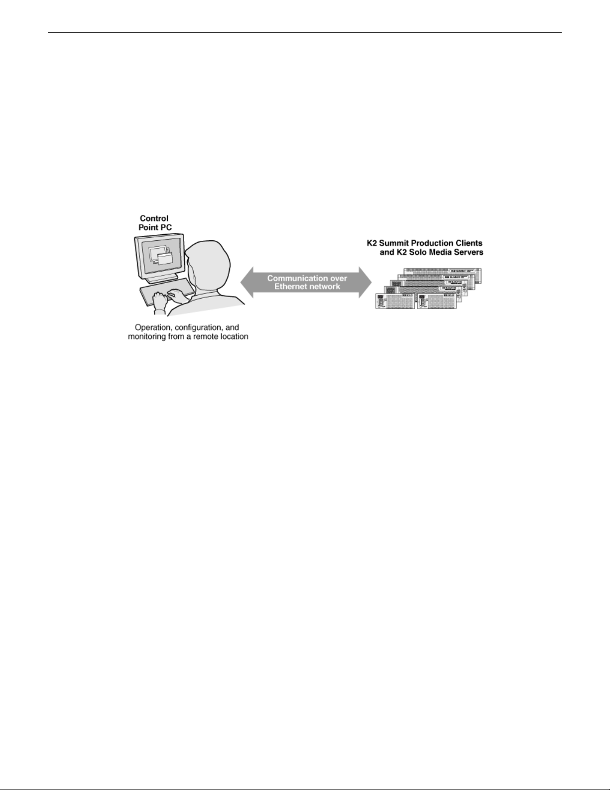
Product description
About K2 systems
The K2 Summit/Solo system is a cost-effective Broadcast Enterprise Server that incorporates IT
server platform and storage technologies to deliver a networked solution to facilities for ingest,
playout, news integration, sports, and media asset management. Each K2 system model is a
comprehensive platform that provides a suite of user applications, system tools, and the largest range
of third-party interactivity in the industry.
The K2 Summit/Solo system is designed for “headless” operation from a remote control point using
Grass Valley Control Point software. You can also use the Microsoft Windows Remote Desktop
Connection application on your PC to connect to the K2 system for conguration or administration.
The K2 Summit/Solo system is further described in the following topics. Also refer to topics on
Transmission models for information unique to those products.
K2 Summit 3G system features
The following features apply to the K2 Summit 3G Production Client:
• Windows 7 64-bit embedded operating system
• Embedded Security for protection against viruses and other unauthorized programs.
• Bidirectional channels (channel can be either an input channel or it can be an output channel)
• Two or four channels per chassis
• SDI video inputs and outputs
• AES/EBU or embedded audio inputs and outputs.
• Standard Denition (SD) video formats and High Denition (HD) video formats
• AVCHD and H.264 play output (decode) as an option.
• 3G codec module hosts codec option cards that are programmable for multiple formats and
functions.
• Mixed format playback of SD or HD clips on the same timeline
• Up/down/cross HD/SD conversion (e.g. SD and HD clips ingested, then played back as SD or
HD clips) or as a different SD or HD format (e.g. 720p to 1080i).
• VGA monitoring capability
• Redundant power supply, cooling fans for reliability
30 K2 System Guide 06 November 2012
Page 31

Product description
• 2.5 inch media storage drives
• mSATA SSD system drive
• Type III CPU carrier module with 8 GB RAM
• USB 3.0 interface for le exchange
• Ability to create nested bins, i.e. sub-bins within bins
• Freeze mode can be frame or eld
• Various video mix effects (e.g. dissolves between two video and audio tracks on the same channel,
or fade thru matte color)
• Remote operation and conguration via AppCenter
• Gigabit Ethernet
• AMP, VDCP, and BVW remote control protocols supported
• Remote control over RS-422 or Ethernet
• Super Slo-Mo, Multi-cam, and 3D/Video + Key features are available as part of the ChannelFlex
Suite
• Low-resolution proxy les created during record and live streamingfrom SDI In/out are available
as part of the AppCenter Pro and Elite licenses
• RAID media storage
• Stand-alone internal storage, stand-alone external direct-connect storage, and external shared
(SAN) storage
Related Topics
Specications on page 215
K2 Summit system features
The following features apply to the rst-generation K2 Summit Production Client:
• Bidirectional channels (channel can be either an input channel or it can be an output channel)
• Two or four channels per chassis
• SDI video inputs and outputs
• AES/EBU or embedded audio inputs and outputs.
• Standard Denition (SD) video formats and High Denition (HD) video formats
• Mixed format playback of SD or HD clips on the same timeline
• Up/down/cross HD/SD conversion (e.g. SD and HD clips ingested, then played back as SD or
HD clips) or as a different SD or HD format (e.g. 720p to 1080i).
• VGA monitoring capability
• Redundant power supply, cooling fans for reliability
• 3.5 inch media storage drives
• CompactFlash system drive
• Ability to create nested bins, i.e. sub-bins within bins
• Freeze mode can be frame or eld
• Various video mix effects (e.g. dissolves between two video and audio tracks on the same channel,
or fade thru matte color)
• Remote operation and conguration via AppCenter
• Gigabit Ethernet
06 November 2012 K2 System Guide 31
Page 32

Product description
• AMP, VDCP, and BVW remote control protocols supported
• Remote control over RS-422 or Ethernet
• Super Slo-Mo, Multi-cam, and 3D/Video + Key features are available as part of the ChannelFlex
• Low-resolution proxy les created during record and live streamingfrom SDI In/out are available
• RAID media storage
• Stand-alone internal storage, stand-alone external direct-connect storage, and external shared
Related Topics
Specications on page 215
K2 Summit Transmission models features on page 198
K2 Solo 3G system features
The following features apply to the K2 Solo 3G Media Server:
Suite.
as part of the AppCenter Pro and Elite licenses. This requires the Type II carrier module.
(SAN) storage
• Windows 7 64-bit embedded operating system
• Embedded Security for protection against viruses and other unauthorized programs.
• Bidirectional channels (channel can be either an input channel or it can be an output channel)
• Two channels per chassis
• SDI video inputs and outputs
• AES/EBU or embedded audio inputs and outputs.
• Standard Denition (SD) video formats and High Denition (HD) video formats
• AVCHD and H.264 play output (decode) as an option.
• 3G codec module. Codec option card not supported on K2 Solo system.
• Mixed format playback of SD or HD clips on the same timeline
• Up/down/cross HD/SD conversion (e.g. SD and HD clips ingested, then played back as SD or
HD clips) or as a different SD or HD format (e.g. 720p to 1080i). Aspect ratios are adjusted.
• VGA monitoring capability
• Compact Flash System drive
• Type III CPU carrier module with 8 GB RAM
• USB 3.0 interface for le exchange
• Ability to create nested bins, i.e. sub-bins within bins
• Freeze mode can be frame or eld
• Various video mix effects (e.g. dissolves between two video and audio tracks on the same channel,
or fade thru matte color)
• Remote operation and conguration via AppCenter
• Gigabit Ethernet
• AMP, VDCP, and BVW remote control protocols supported
• Remote control over RS-422 or Ethernet
• ExpressCard
• Super Slo-Mo, Multi-cam, and 3D/Video + Key features are available as part of the ChannelFlex
Suite.
32 K2 System Guide 06 November 2012
Page 33

• Low-resolution proxy les created during record and live streamingfrom SDI In/out are available
as part of the AppCenter Pro and Elite licenses. This requires the Type II carrier module.
• RAID 0 internal media storage
• Support for Dyno S.
K2 Solo system features
The following features apply to the rst-generation K2 Solo Media Server:
• Bidirectional channels (channel can be either an input channel or it can be an output channel)
• Two channels per chassis
• SDI video inputs and outputs
• AES/EBU or embedded audio inputs and outputs.
• Standard Denition (SD) video formats and High Denition (HD) video formats
• Mixed format playback of SD or HD clips on the same timeline
• Up/down/cross HD/SD conversion (e.g. SD and HD clips ingested, then played back as SD or
HD clips) or as a different SD or HD format (e.g. 720p to 1080i). Aspect ratios are adjusted.
• VGA monitoring capability
• CompactFlash system drive
• Ability to create nested bins, i.e. sub-bins within bins
• Freeze mode can be frame or eld
• Various video mix effects (e.g. dissolves between two video and audio tracks on the same channel,
or fade thru matte color)
• Remote operation and conguration via AppCenter
• Gigabit Ethernet
• AMP, VDCP, and BVW remote control protocols supported
• Remote control over RS-422 or Ethernet
• ExpressCard
• Super Slo-Mo, Multi-cam, and 3D/Video + Key features are available as part of the ChannelFlex
Suite.
• Low-resolution proxy les created during record and live streamingfrom SDI In/out are available
as part of the AppCenter Pro and Elite licenses. This requires the Type II carrier module.
• RAID 0 internal media storage
Product description
K2 Summit/Solo formats, models, licenses, and hardware support
Formats are supported as in the following tables.
Table 1: First-generation K2 Summit/Solo system
1xCompressionFormats
+ Key
06 November 2012 K2 System Guide 33
Super Slo-MoMulti-Cam, 3D/Video
Not supported.Encode/decodeEncode/decodeDVSD
Page 34

Product description
MPEG-2
DV1080i/720p
MPEG-2
AVC-Intra
1xCompressionFormats
Encode requires
codec option card.
Encode/decode.
Requires HD
license.
Encode requires
codec option card.
Requires HD
license.
Encode/decode.
Requires coded
option card.
Requires HD
license.
+ Key
Encode/decode.
Requires HD
license.
Requires coded
option card.
Requires HD
license.
Super Slo-MoMulti-Cam, 3D/Video
Not supported.Not supported.Decode is standard.
Not supported.Not supported.Not supported.AVCHD
Encode/decode.
Requires HD
license.
Not supported.Not supported.Decode is standard.
Not supported.Encode/decode.
Not supportedNot supportedNot supportedAVCHD
Table 2: K2 Summit 3G system
AVCHD/H.264
DV1080i/720p
MPEG-2
AVC-Intra
1xCompressionFormats
Encode/decodeMPEG-2
Requires AVC
license.
Encode/decode. HD
license is standard.
Encode/decode. HD
license is standard.
Encode/decode.
Requires AVC
license. HD license
is standard.
+ Key
Requires codec
option card.
Encode/decode. HD
license is standard.
Requires codec
option card. HD
license is standard.
Encode/decode.
Requires AVC
license. HD license
is standard.
Super Slo-MoMulti-Cam, 3D/Video
Not supported.Encode/decodeEncode/decodeDVSD
Not supported.Encode/decode.
Not supportedNot supportedDecode only.
Encode/decode. HD
license is standard.
Not supported.Encode/decode.
Encode/decode.
Requires AVC
license. HD license
is standard.
34 K2 System Guide 06 November 2012
Page 35

Product description
AVCHD/H.264
Table 3: K2 Solo 3G system
AVCHD/H.264
DV1080i/720p
MPEG-2
1xCompressionFormats
Requires AVC
license.
1xCompressionFormats
Requires AVC
license.
Encode/decode. HD
license is standard.
license is standard.
+ Key
+ Key
Encode/decode. HD
license is standard.
Super Slo-MoMulti-Cam, 3D/Video
Not supportedNot supportedDecode only.
Super Slo-MoMulti-Cam, 3D/Video
Not supported.Encode/decodeEncode/decodeDVSD
Not supportedNot supportedEncode/decodeMPEG-2
Not supportedNot supportedDecode only.
Encode/decode. HD
license is standard.
Not supportedNot supportedEncode/decode. HD
AVC-Intra
Encode/decode.
Requires AVC
license. HD license
is standard.
AVCHD/H.264
Requires AVC
license.
Features of internal storage models
K2 Summit/Solo systems have media drives as follows:
• First generation K2 Summit system — Up to eight media drives
• K2 Summit 3G system — Up to twelve media drives
• K2 Solo Media Server — Two media drives
• K2 Solo 3G Media Server — Two media drives
This makes the internal storage K2 system a self-contained, stand-alone unit, with no external devices
for storage connections required. You can transfer media in and out of the internal storageK2 system
via Gigabit Ethernet. You can also export media to a mapped drive or USB-attached storage. With
the K2 Solo Media Server, you can also export media via an ExpressCard.
Encode/decode.
Requires AVC
license. HD license
is standard.
Encode/decode.
Requires AVC
license. HD license
is standard.
Not supportedNot supportedDecode only.
06 November 2012 K2 System Guide 35
Page 36

USB compartment
(Clip behind bezel)
Note: removing the bezel takes
the fans offline. Replace the bezel assembly
within one minute to maintain system cooling.
Serial Number
This is also the factory
default hostname
Product description
Features of external storage models
The external storage K2 Summit system contains only the system drive. There are no media drives
in an external storage K2 Summit system. There are two types of external storage for media, as
follows:
• Shared storage — Multiple external storage K2 Summit systems connect to the K2 SAN via
• Direct-connect storage — A single K2 Summit system with the optional Fibre Channel board
Product identification K2 Summit 3G
The K2 Summit 3G system has labels afxed to the chassis that provide product identication as
illustrated:
Gigabit Ethernet or Fibre Channel to share a common pool of storage.
installed connects directly to its own external (non-shared) RAID storage device. This makes
the direct-connect K2 Summit system a self-contained, stand-alone unit, with no additional
devices for storage connections required. You can transfer media in and out of the direct-connect
K2 Summit system via Gigabit Ethernet.
Product identification first generation K2 Summit
36 K2 System Guide 06 November 2012
The rst generation K2 Summit system has labels afxed to the chassis that provide product
identication as illustrated:
Page 37

Serial Number
This is also the factory
default hostname
USB compartment
(Compartment swivels up.)
Note: removing the bezel takes
the fans offline. Replace the bezel assembly
within one minute to maintain system cooling.
C1 C2 C3 C4
!
OK
~AC
!
OK
~AC
SDIIN1 S DI OUT1 S DI OUT2
LTCI/O
AESAUDIO R S422
SDIOUT1 SDI OUT2
USB/1394 100BT/1000BT
GPI
VGA REF.LOOPTHROUGH
AESAUDIO R S422
LTCI/O
SDIIN2 S DI IN3 SDI IN1 S DI IN2 S DI IN3 SDIIN1 S DI OUT1 S DI OUT2
LTCI/O
AESAUDIO R S422
SDIOUT1 SDI OUT2
AESAUDIO R S422
LTCI/O
SDIIN2 S DI IN3 SDI IN1 S DI IN2 S DI IN3
Type II label
Identifies Type II carrier module
Serial Number
This is also the factory
default hostname
Product description
Product identification K2 Solo
K2 Solo system have labels afxed to the chassis that provide product identication as illustrated:
Front panel indicators K2 Summit 3G system
With the front bezel in place, the indicator LEDs are visible. The LEDs indicate the status of the
06 November 2012 K2 System Guide 37
machine. For example, when the Service LED is a steady yellow light, this could signify that one
Page 38
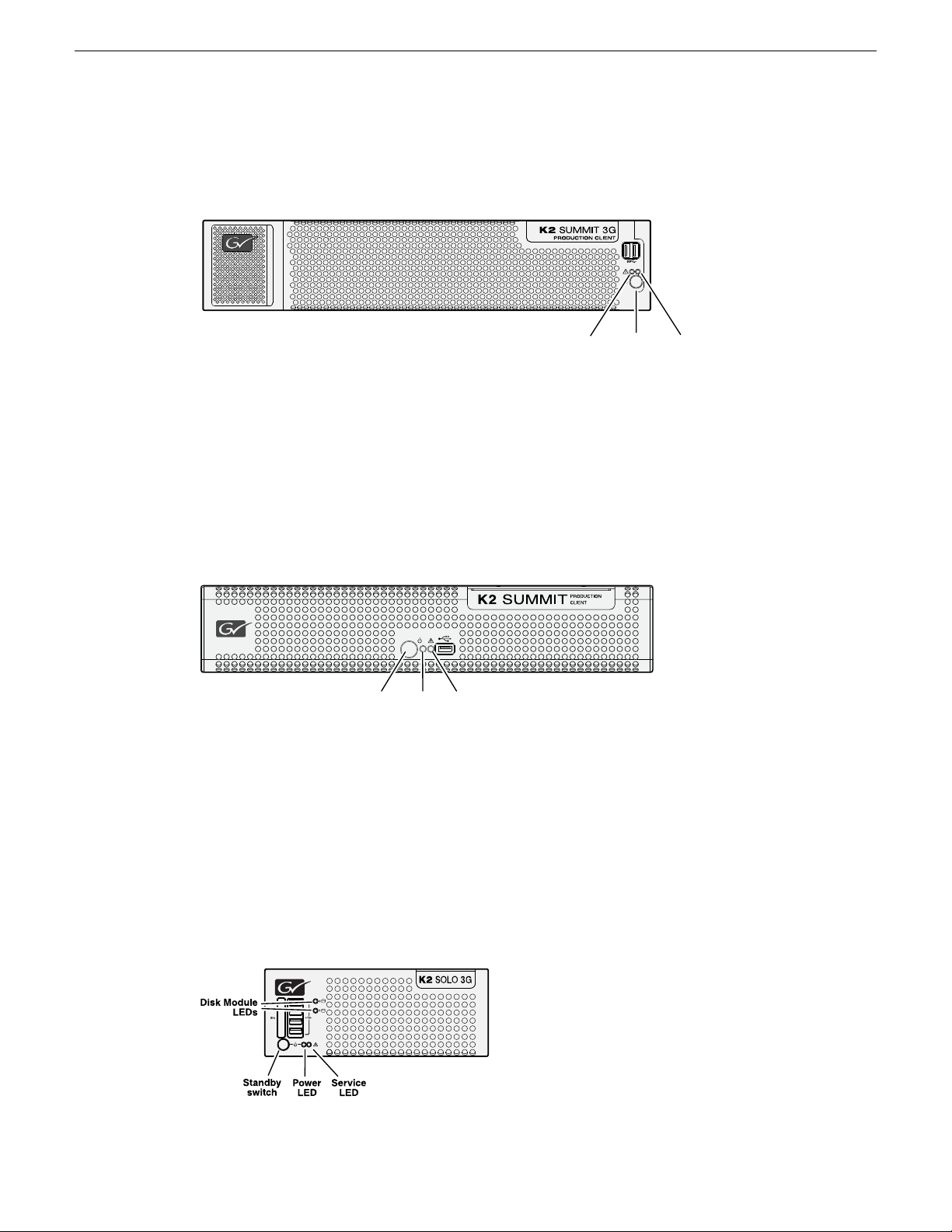
Power
LED
Standby
switch
Service
LED
Power
LED
Standby
switch
Service
LED
Product description
of the power cables is unplugged. For more information on indicator LEDs, see the service manual
for your K2 product.
Front panel indicators first-generation K2 Summit
With the front bezel in place, the indicator LEDs are visible. The LEDs indicate the status of the
machine. For example, when the Service LED is a steady yellow light, this could signify that one
of the power cables is unplugged. For more information on indicator LEDs, see the service manual
for your K2 product.
Front panel indicators K2 Solo
Both the rst-generation K2 Solo system and the K2 Solo 3G system have the same front panel
indicators. With thefront bezel in place, the indicator LEDsare visible. The LEDs indicate the status
of the machine. For example, when the Service LED is a steady yellow light, this could signify that
one of the power cables is unplugged. For more information on indicator LEDs, see the service
manual for your K2 product.
38 K2 System Guide 06 November 2012
Page 39

Rear panel view
!
OK
~AC
C1 C2 C3 C4
USB/1394
100BT/1000BT
GPI
VGA
REF.LOOP THROUGH
!
OK
~AC
OK
Power
Power
Port 1: Control
Port 2: FTP/Streaming
Control Connection #1
Control Connection #2
Media Connection #1
Port 4: Control
(Optional)
Port 1: Control A
Control Connection #1
Control Connection #2
Media Connection #1
Port 4: Control B
for redundant SAN
Port 2: Media (iSCSI) A
Media Connection #2
Port 3: Media (iSCSI) B
for redundant SAN
IEEE
1394
(Do not
use)
Optional Fibre Channel
card for connection to
direct-connect storage
or shared (SAN) storage
Reference
Loop Thru
VGA
monitor
USB
(keyboard,
mouse)
GPI
Channel 1
Stand-alone direct-connect
or internal storage
Shared (SAN)
storage
Channel 2 Channel 3 Channel 4
Control Connections are teamed
and share the same IP address
c
c c
c
c
Supports
Channel Flex Suite,
which requires
AppCenter
Elite license
a
Supports Super Out,
which requires
AppCenter Pro or
Elite license
b
RS-422
(connect via optional
multi-connector cable)
LTC in/out
AES audio
SDI video in and out supports embedded audio.
SDI in
SDI out SDI monitor out.
Channel Flex
aa a a, b
The following illustrations identify the rear panel connectors and components.
K2 Summit 3G models rear panel
Product description
06 November 2012 K2 System Guide 39
Page 40

RS-422
SDI video in and out supports embedded audio.
(connect via optional
multi-connector cable)
LTC in/out
AES audio
Power
Power
Port 1: Control
Port 2: FTP/Streaming
Control Connection #1
Control Connection #2
Media Connection #1
Port 4: Control
(Optional)
Port 1: Control A
Control Connection #1
Control Connection #2
Media Connection #1
Port 4: Control B
for redundant SAN
Port 2: Media (iSCSI) A
Media Connection #2
Port 3: Media (iSCSI) B
for redundant SAN
IEEE
1394
(Do not
use)
Optional Fibre Channel
card for connection to
direct-connect storage
or shared (SAN) storage
Reference
Loop Thru
VGA
monitor
USB
(keyboard,
mouse)
GPI
Channel 1
Stand-alone direct-connect
or internal storage
Shared (SAN)
storage
Channel 2 Channel 3 Channel 4
Control Connections are teamed
and share the same IP address
c
c c
c
c
SDI in SDI out SDI monitor out.
Channel Flex
aa a a, b
Supports
Channel Flex Suite,
which requires
AppCenter
Elite license
a
Supports Super Out,
which requires
AppCenter Pro or
Elite license
b
Product description
K2 Summit first generation models rear panel
40 K2 System Guide 06 November 2012
Page 41
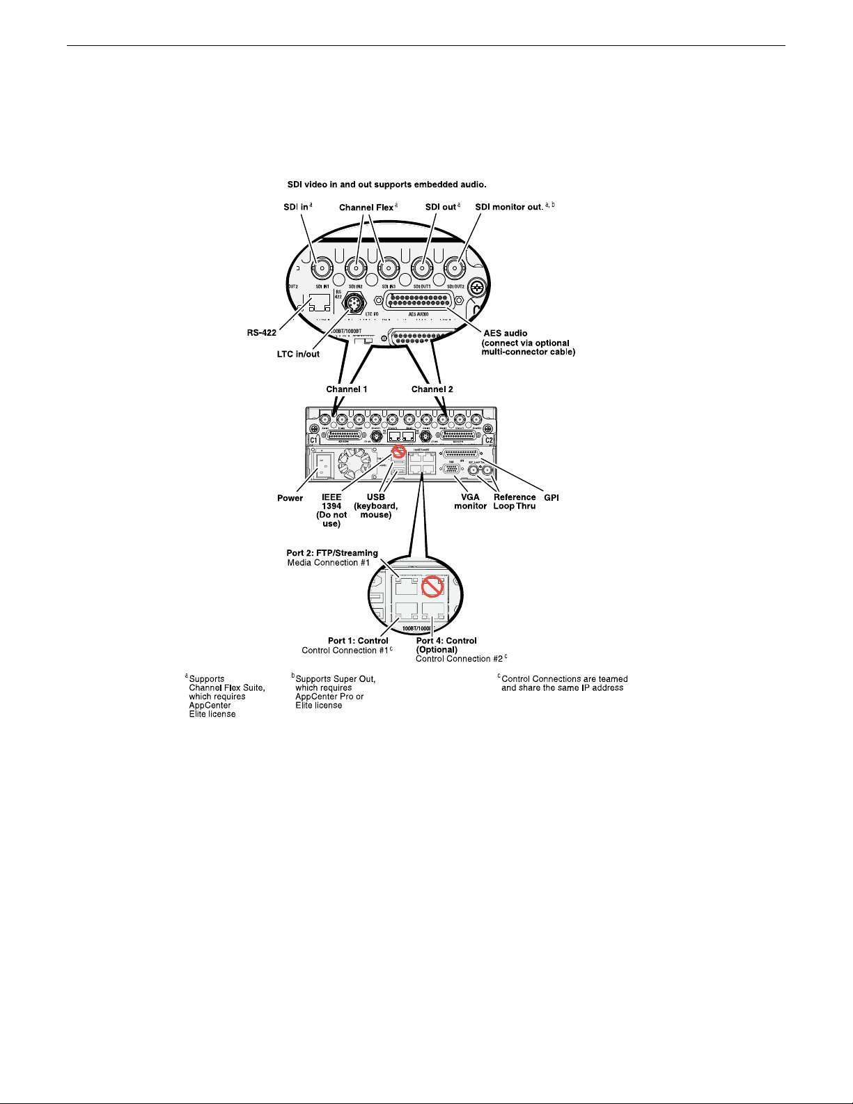
K2 Solo 3G Media Server rear panel
Product description
06 November 2012 K2 System Guide 41
Page 42

RS-422
SDI in SDI out SDI monitor out.
(connect via optional
multi-connector cable)
LTC in/out
AES audio
Power
Port 1: Control
Port 2: FTP/Streaming
Control Connection #1
Control Connection #2
Media Connection #1
Port 4: Control
(Optional)
IEEE
1394
(Do not
use)
Reference
Loop Thru
VGA
monitor
USB
(keyboard,
mouse)
GPI
Channel 1 Channel 2
Channel Flex
SDI video in and out supports embedded audio.
Supports
Channel Flex Suite,
which requires
AppCenter
Elite license
a
aa a a, b
Supports Super Out,
which requires
AppCenter Pro or
Elite license
b
Control Connections are teamed
and share the same IP address
c
c
c
Product description
K2 Solo Media Server rear panel
ChannelFlex rear panel connections
ChannelFlex Suite features require the AppCenter Elite license. Super Slo-Mo also requires the HD
license. When congured for these features, channel connections are as follows:
42 K2 System Guide 06 November 2012
Page 43

Phase 1 Phase 2 Phase 3
Super Slo-Mo Recorder
Video 1 Video 2
Multi-Cam Recorder
Video or
Left eye
Key or
Right eye
3D/Video + Key Recorder
Video or
Left eye
Key or
Right eye
3D/Video + Key Player
Product description
Considerations for first startup out of box
K2 Summit/Solo system overview
Refer to the K2 AppCenter User Manual for more information on ChannelFlex Suite features.
When youreceive aK2 systemfrom thefactory, one or more End User License Agreements (EULAs)
appear on the screen at rst startup. Software licensing agreements require that you accept these
EULAs. When you do so, start up processes can proceed. This behavior occurs only at rst startup.
Subsequent startups do not exhibit this behavior.
The K2 Summit/Solo system are purpose-built clients based on COM Express compact computer
with dedicated systems to provide the video disk recorder functionality. This section explains the
major architectural blocks.
Related Topics
Application System on page 44
Real Time System on page 44
Media control and processing on page 44
Loop through, E to E, and feeds on page 45
06 November 2012 K2 System Guide 43
Page 44

Product description
Application System
The K2 Summit Production Client and K2 Solo Media Server application system architecture uses
the COM Express form factor to provide functionality similar to that of standard PC-type computers.
The carrier module contains a CPU module, built in Ethernet, and USB ports. On the K2 Summit
Production Client, the carrier module also includes one PCIe board slot for expansion.
The Applicationsystem uses a Windows embedded operating system upon which all internal storage
K2 system applications run for conguration and control of the unit.
Real Time System
Each channel hosts a complete Real Time system that provides the core video disk recorder
functionality. Primary components are as follows:
• Dedicated processor for media access and processing.
• Codec circuits responsible for encoding/decoding video and processing audio and timecode,
including the media-related input and output connectors.
The Real Time system uses a dedicated operating system. This operating system manages all the
hardware involved in controlling the ow of video, audio, timecode, genlock, and GPI in and out
of the K2 system.
Media control and processing
The following section explains how the Applicationsystem and the Real Time system work together
to provide K2 system functionality.
The high processing requirements of digital video can overwhelm the processor on a standard desktop
PC, resulting in wait-times that destroy the video’s essential real-time aspect. The K2 system avoids
this problem by providing dedicated systems that isolate processing needs. The components that
work together to provide this functionality are as follows:
Application system — Dedicated to control, conguration, and networking functions that do not
require real-time accuracy. The Application system has the following components:
• Application software provides the user interface for operating the K2 system. The software runs
as Windows programs.
• The Media File system manages clips. It includes a database that associates the clip with its
video, audio, and timecode les and a dedicated le system (separate from the Windows le
system) that controls access to the raw data that makes up each le. Any reading and writing of
clips, be it through play and record operations or through le transfers and media streaming, is
managed by the database. The database and le system run as Windows programs.
Storage system — Includes the media disk drives, controllers, drivers, and adapters necessary for
access and movement of the data. While the primary data ow is within the overall control of the
Real Time system, some components and their communication pathways cross over into the
Application system. For example, the media drives appear as the V: drive to the Windows operating
system.
44 K2 System Guide 06 November 2012
Page 45

Product description
Real Time system —Manages themedia owbetween theStorage systemand theinputs andoutputs.
The Real Time system has dedicated processors and time-sensitive mechanisms to serve media
processing needs while maintaining real-time accuracy.
When you control play and record operations from within the Application system you trigger achain
of events that eventually crosses over into the Real Time system and results in media access. The
following sequence is an example of this type of chain of events:
1. A user operates the Player application to play a particular clip. The Player application asks the
Media File system for permission to access the clip. The Media File system grants access. In
shared storage models, the Media File system enforces shared storage policies in order to grant
the access. When access is granted, the Player application initiates play access to the clip.
2. The database identies the les that make up the clip and the le system instructs the Storage
system to open access to the les.
3. The Storage system nds the raw data and opens the appropriate read access. At this point both
the Application system and the Real Time system are involved. Windows controls the media
drives and controllers, so the Real Time system makes le requests to Windows and it causes
the data to be transferred to buffers on the Real Time processor. The data is then available to the
Real Time system so that it can be processed at exactly the right time.
4. The Real Time system processes the media, decompresses it, adjusts its timing, and moves it as
required to play the clip as specied by the user.
Loop through, E to E, and feeds
Behaviors related to input signals routed to output connectors are described in the following topics.
Related Topics
Remote control protocols on page 209
Recording synchronous and asynchronous feeds
For best results in all workows, use synchronous feeds, dened as follows:
• All outputs are locked to the house reference
• All inputs are genlocked to the house reference and at zero time
The K2Summit ProductionClient andK2 SoloMedia Servercan recordinputs thatare asynchronous,
with the following considerations:
• The encoder clock and the audio clock are derived from the input signal, which enables frame
accurate recording of all inputs.
• Outputs are timed to the reference and if no reference is present, the output runs free.
• If the input video rate does not equal the output video rate (asynchronous) then video tearing or
jumping can occur when input/output synch is critical, such as in the following:
• K2 TimeDelay
• SD-00 or Summit E-to-E (LoopThru) mode
• HD-00 Loopback
06 November 2012 K2 System Guide 45
Page 46

Product description
Loop through on K2 Summit/Solo
The Player/Recorder application has a “E-to-E (LoopThru) mode” selection on the Control menu.
This mode applies when the channel is under local AppCenter control as well as when it is under
remote control, for all protocols.
This “E-to-E (LoopThru) mode” feature allows you to monitor the video that is being recorded. The
video is routed back essentially untouched. Any audio or timecode that is on the input video stream
is still there on the loop through output. The K2 Summit/Solo system and the loop through videos
must be locked to a video reference for the loop through feature to work properly. This “E-to-E
(LoopThru) mode” feature should not be confused with true E to E. True E to E is not supported on
the K2 Summit/Solo system.
When “E-to-E (LoopThru) mode” is not selected, the channel behaves as follows:
• “PB” is displayed on the channel pane, next to the Timecode Source indicator.
• When no clip is loaded, black plays out.
• When a record operation stops, Recorder becomes Player and the clip remains in the Player. The
clip’s last frame plays out.
When “E-to-E (LoopThru) mode” is selected, the channel behaves as follows:
• “EE” is displayed on the channel pane, next to the Timecode Source indicator.
• When no clip is loaded, the signal that is currently present at the channel input plays out.
• When a record operation stops, Recorder stays Recorder and the clip remains in the Recorder.
The signal that is currently present at the channel input plays out.
Ports used by K2 services
The following ports are used by the applications and system tools of the K2 family of products:
20
21
161
162
3389
3811
8080
8100
8732
8733
8734
8735
TCP: Used by mpgsession.exe, mxfsession.exe, gxfsession.exe, or ftpd.exe for FTP.
TCP: Used by ftpd.exe for FTP data.
UDP: Used by snmp.exe for SNMP.
UDP: Used by snmptrap.exe for SNMP trap.
TCP: Used by Remote Desktop for use by SiteCong.
TCP: Used by Grass Valley AppService for 3rd party applications to communicate
using AMP protocol. Used by SDB and XMOS Server AMP Communication.
HTTP: Used by STRATUS Summit Services.
HTTP: Used by Macintosh systems for the SabreTooth licensing web service to
check out licenses
HTTP: Used by Site Cong data service .
HTTP: Used by K2 Cong data service .
HTTP: Used by Site Cong data service .
HTTP: Used by K2 Cong data service.
46 K2 System Guide 06 November 2012
Page 47

Disk0Disk1Disk2Disk3Disk4Disk5Disk6Disk7Disk8Disk9Disk10Disk
11
Product description
18262
18263
18264
31820
49168
49169
49170
49171
49172
50872
TCP: Used by GV ProductFrame Conguration Service, ProductFrame Discovery
Agent Service for use by SiteCong. Used by GV NetCong Service. gv-pf. UDP:
Used by GV NetCong Service. gv-pf.
UDP: Used by ProductFrame Discovery Agent Service for GV NetCong Device
Broadcast/Unicast Protocol. Used by SiteCong. Sent by ControlPoint, received
by Devices
UDP: Usedby ProductFrameDiscovery Agent Service for GV NetCong Controller
Protocol. Used by SiteCong. Sent by Devices, received by ControlPoint
UDP: Used for live streaming from K2 Summit/Solo systems. This is the default
base for UDP ports, with the rangebeing 31820 to 31827. Other ranges are possible,
depending on the UDP port base congured on the K2 Summit/Solo system.
HTTP: Used by Grass Valley K2 Cong for K2Cong application connection
between a control point PC and the K2 system device congured. Used for most
functions.
TCP: Usedby GrassValley K2 Cong for K2Cong application connection between
a control point PC and the K2 system device congured. Used for a few functions
that require longer time periods.
HTTP: Used by Grass Valley Transfer Queue Service for Transfer Manager
connection between source system and destination system.
TCP: Used by Grass Valley AppService for AppCenter connection between control
point PC and K2 client/Solo.
HTTP: Used by Grass Valley Storage Utility Hostfor connection for Storage Utility
between the control point PC and the K2 system being congured.
UDP: Used by K2 Appcenter to discover K2 systems on the network.
RAID drive numbering K2 Summit 3G system
In the K2 Summit 3G system, internal RAID drives are numbered as follows. This numbering is
displayed in Storage Utility.
Drives are congured as RAID 1.
ExplanationDrive numbering
These two RAID drives make up LUN 0.Disk 0
Disk 1
These two RAID drives make up LUN 1.Disk 2
Disk 3
06 November 2012 K2 System Guide 47
Page 48

Disk 2 Disk 4 Disk 7
Disk 1 Disk 3 Disk 6
Disk 0 Disk 5
Product description
Disk 5
Disk 7
Disk 9
Disk 11
RAID drive numbering first generation K2 Summit system
In the rst generation K2 Summit system, internal RAID drives are numbered as follows. This
numbering is displayed in Storage Utility. You cannotsee thelabeling on the K2 Summit Production
Client chassis RAID drive when you remove the fan module.
ExplanationDrive numbering
These two RAID drives make up LUN 2.Disk 4
These two RAID drives make up LUN 3.Disk 6
These two RAID drives make up LUN 4.Disk 8
These two RAID drives make up LUN 5.Disk 10
ExplanationDrive numbering
When congured as RAID 1, these two RAID drives make up LUN 0.Disk 0
Disk 1
When congured as RAID 1, these two RAID drives make up LUN 1.Disk 2
Disk 3
When congured as RAID 1, these two RAID drives make up LUN 2.Disk 4
Disk 5
When congured as RAID 1, these two RAID drives make up LUN 3.Disk 6
Disk 7
When drives are congured as RAID 0, each drive is considered its own LUN. As such, the order
of LUNs and drive numbers as displayed in Storage Utility does not always correlate with the position
of drives in the chassis.
48 K2 System Guide 06 November 2012
Page 49

RAID drive numbering K2 Solo system
Disk 0
Disk 1
In the K2 Solo system, internal RAID drives are numbered as follows.
NOTE: K2 Solo system drives are always congured as RAID 0.
When drives are congured as RAID 0, each drive is considered its own LUN. As such, the order
of LUNs and drive numbers as displayed in Storage Utility does not always correlate with the position
of drives in the chassis.
Product description
06 November 2012 K2 System Guide 49
Page 50

Product description
50 K2 System Guide 06 November 2012
Page 51

Chapter 2
Overview of K2 System Tools
This section contains the following topics:
• Conguration Manager
• K2Cong
• Storage Utility for standalone K2 Summit/Solo system
• Remote Desktop Connection
• About SiteCong
06 November 2012 K2 System Guide 51
Page 52

Overview of K2 System Tools
Configuration Manager
The CongurationManager is the primary conguration tool for a K2 Summit/Solo system. It makes
settings that apply to the overall internal storage K2 Summit/Solo system as well as settings that
apply to individual channels.
Conguration Manager settings are stored in a database. When the K2 Summit/Solo system starts
up it reads the current settings from the database and congures itself accordingly. When you modify
a setting in Conguration Manager you must save the setting in order to update the database and
recongure the K2 Summit/Solo system.
You can also save settings out of Conguration Manager into a conguration le, which is a
stand-alone XML le. Likewise, you can load settings into Conguration Manager from a
conguration le. However, you must use Conguration Manager as the means to save the settings
to the database before the settings actually take effect. Conguration les are not linked directly to
the database.
You can use conguration les as a means to back up your settings. You can also use conguration
les to save several different groups of customized settings, each with a unique name, so that you
can quickly load settings for specialized applications.
If you save a conguration le and then upgrade your K2 systemsoftware, there can be compatiblity
issues. If the upgraded software version has new features, the saved conguration le might not be
compatible.
52 K2 System Guide 06 November 2012
Page 53

Accessing Configuration Manager
You access Conguration Manager through the K2 AppCenter application from the local K2
Summit/Solo system or from the Control Point PC.
To access the conguration settings, open AppCenter and select System | Configuration.
Overview of K2 System Tools
Saving and restoring Configuration Manager settings
Settings can be saved as a conguration le. You can save any number of uniquely named custom
conguration les. You can load a conguration le to restore system settings.
To save custom settings:
1. In the Conguration Manager, click the Save button.
The Save As dialog opens.
2. Use the up arrow or select folders to navigate to the folder in which you want to save the
conguration le.
3. Enter a name for the conguration le.
Do not name the le DefaultCong.xml, as this name is reserved for the factory default
conguration le. Otherwise, standard Windows 2000 and up le naming restrictions apply.
4. Click Save and Close.
06 November 2012 K2 System Guide 53
Page 54

Overview of K2 System Tools
To restore custom settings:
1. If you wantto save current settings, you should save them as a conguration le before continuing.
2. In the Conguration Manager, click the Load button.
The Open dialog opens.
3. Use the up arrow or select folders to navigate to the custom conguration le.
4. Select the custom conguration le.
5. Click Open.
The custom settings are loaded into Conguration Manager, but they have not been saved and
put into effect.
6. Click OK to save and apply settings, and to close the Conguration Manager.
Restoring default Configuration Manager settings
You can restore factory default settings as follows:
• Restore some individual settings or groups of settings by selecting the Default button which
appears below the settings in the conguration screen.
• Restore all the settings in Conguration Manager at once to their default values as explained in
the following procedure.
1. If you want to save current settings you should do so before proceeding.
2. In the Conguration Manager dialog, click Restore.
3. Click OK to save settings and close Conguration Manager.
Related Topics
Saving and restoring Conguration Manager settings on page 53
K2Config
The K2 System Conguration application (K2Cong) is the primary tool for conguring systems
in the category of a K2 SAN, which include online or production K2 SANs, K2 Nearline systems,
and STRATUS Proxy Storage systems. Once the devices of the storage system are cabled and are
communicating on the control network, you can do all the conguration requiredto create a working
K2 SAN using the K2Cong application. When you use SiteCong for network conguration, you
can import the SiteCong system description le into the K2Cong application to get you started
with your SAN conguration.
After your K2 SAN is initially installed and congured, if you need to recongure the system you
should do so using SiteCong and the K2Cong application. This enforces consistent policy and
sequencing for conguration tasks, which makes the system easier to maintain and aids in
troubleshooting should a problem arise.
The default settings are loaded into Conguration Manager, but they have not yet been saved
and put into effect.
54 K2 System Guide 06 November 2012
Page 55

Overview of K2 System Tools
The K2Cong application runs on a control point PC and accesses the devices of the K2 SAN via
the control network. You can congure the devices of the K2 SAN as follows:
• SAN-attached K2/Summit systems and K2 Media Server — These devices are congured directly
by the K2Cong application.
• K2 RAID storage devices — The K2Cong application launches a remote instance of Storage
Utility, which congures RAID storage devices. Storage Utility components run on the K2 Media
Server and the conguration actually takes place via the Fibre Channel connection between the
K2 Media Server and the RAID storage device.
• Ethernet switches — The K2Cong application can launch a switch’s web-based conguration
application.
You can expand and select nodes in the tree view to view K2 SANs, individual devices, and
conguration settings. The conguration le is saved on the V: drive, along with the media les in
the shared storage system. The conguration le is updated and saved whenever you change a
conguration using the K2Cong application. That is why you must always use the K2Cong
application to change settings on the storage system, so the most recently changed congurations
will always be stored in the conguration le and displayed.
Opening the K2Config application
1. On the control point PC open the K2Cong application shortcut on the desktop. The K2Cong
application log in dialog box opens.
2. Log in using the designated administrator account for conguring K2 SAN devices.
06 November 2012 K2 System Guide 55
Page 56
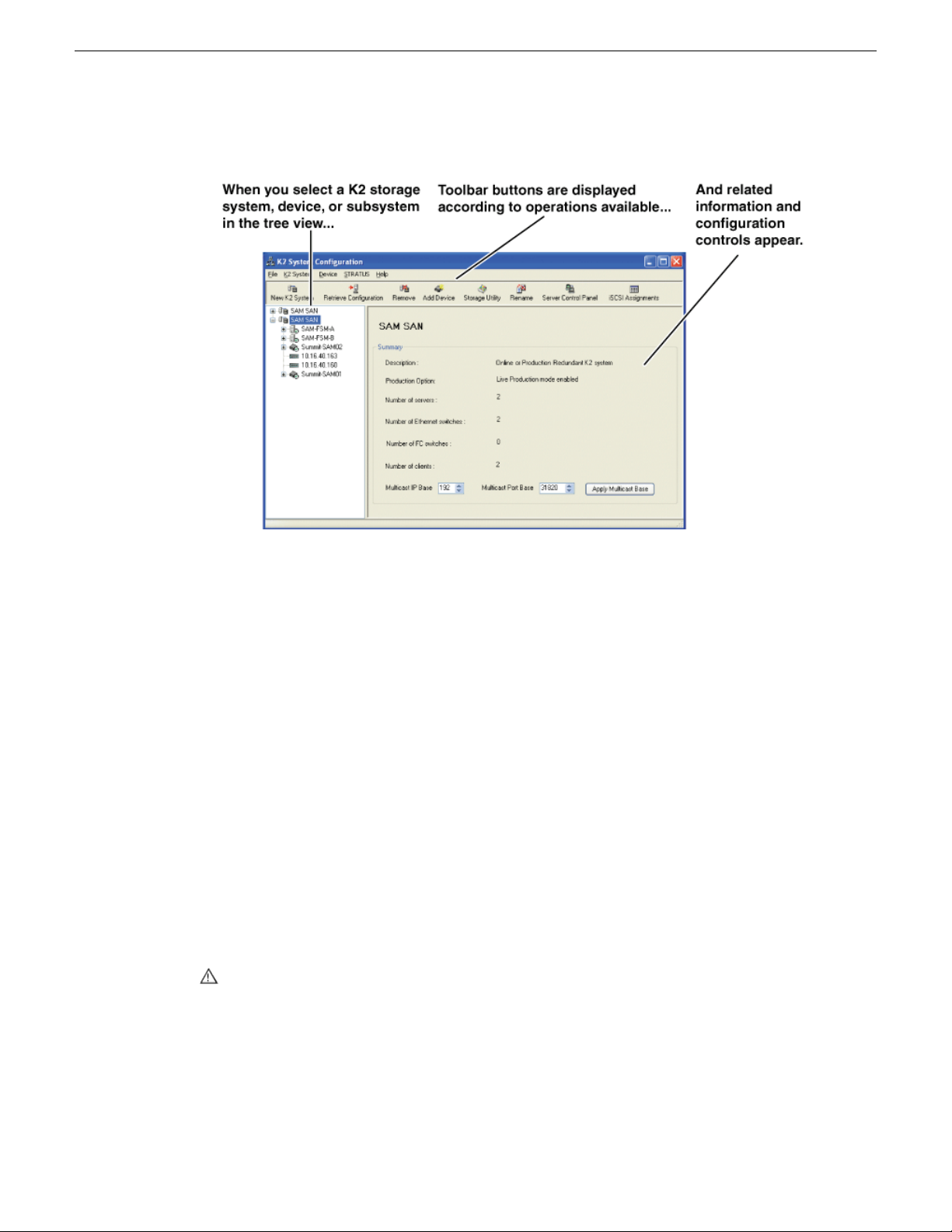
Overview of K2 System Tools
3. The K2Cong application opens.
If you have one or more K2 SANs currently congured, the K2Cong application displays the
systems in the tree view.
If you have not yet congured a K2 SAN, the K2Cong application opens with the tree view
blank.
Storage Utility for standalone K2 Summit/Solo system
There are two versions of Storage Utility:
• Storage Utility for the K2 SAN
• Storage Utility for stand-alone K2 systems
This manual explains Storage Utility for stand-alone K2 Summit/Solo system. Refer to the K2 SAN
Installation and Service Manual to learn about Storage Utility for the K2 SAN.
NOTE: For shared storage, run Storage Utility only via the K2Cong application.
The Storage Utility is your primary access to the media le system, the media database, and the
media disks of the K2 Summit/Solo system for conguration, maintenance, and repair. It is launched
from the K2 AppCenter application.
CAUTION: Use the Storage Utility only as directed by a documented procedure or by Grass
Valley Support. If used improperly, the Storage Utility can render your K2 system inoperable
or result in the loss of all your media.
NOTE: Do not use the MegaRAID utility on a K2 system. This utility is for use by qualied Grass
Valley Service personnel only. When this utility is opened it scans the SCSI bus and interferes
with record and play operations.
56 K2 System Guide 06 November 2012
Page 57

Remote Desktop Connection
You can use the Microsoft Windows Remote Desktop Connection application to make a remote
connection to a Grass Valley system that runs the Windows operating system.
Take the following into consideration when connecting to K2 systems:
• Before you can use the Remote Desktop Connection, you need network access and permissions
to connect to the K2 system.
• You can use either the name or the IP address to access the K2 system.
• Do not use the Remote Desktop Connection to access the PC running the Control Point software
or to access the AppCenter application; results may be unreliable.
• Take care when accessing an online K2 system on which media access is underway. The additional
load on network and system resources could cause unpredictable results.
• Lack of robust video/graphic support can cause video display problems. Remote desktop
connections can interrupt proxy and live streaming. AppCenter video monitoring is not supported
through Remote Desktop Connection.
Overview of K2 System Tools
Accessing Remote Desktop Connection
1. Do one of the following:
• Click the Start button on the Windows task bar
• Press the Windows key on the keyboard.
2. Select Programs | Accessories | Communications | Remote Desktop Connection.
The Remote Desktop dialog box opens.
3. Enter the name or IP address of the system to which you are making the remote connection and
click Connect.
About SiteConfig
SiteCong is Grass Valley's tool for network conguration and software deployment. SiteCong
is a ProductFrame application. ProductFrame is an integrated platform of tools and product
distribution processes for system installation and conguration.
You can use SiteCong as a stand-alone tool for planning and system design, even before you have
any devices installed or cabled. You can dene networks, IP addresses, hostnames, interfaces, and
other network parameters. You can add devices, group devices, and modify device roles in the
system.
As you install and commission systems, SiteCong runs on a designated PC. It discovers devices,
congures their network settings, and manages host les. SiteCong also manages software
installations and upgrades and provides a unied software package with compatible versions for
deployment across multi-product systems.
You should use SiteCong for network conguration and software deployment at installation and
throughout the life of the system in your facility. This enforces consistent policy and allows SiteCong
06 November 2012 K2 System Guide 57
Page 58

Overview of K2 System Tools
to keep a record of changes, which makes the system easier to maintain and aids in troubleshooting
should a problem arise.
SiteCong displays information from a system description le, which is an XML le.
Opening SiteConfig
1. Do one of the following: Use the SiteCong shortcut on the Windows desktop or in the Start
menu to open SiteCong.
• On the Windows desktop, click the Grass Valley SiteConfig shortcut.
• On the Windows Start menu, in the Grass Valley folder, click the SiteConfig shortcut.
2. SiteCong opens as follows:
• If you have previously opened SiteCong, the SiteCong main window opens with the most
recently used system description loaded.
• If you have not previously used SiteCong or if SiteCong does not have access to a system
description le, you are prompted to create a new system description or to import an existing
system description.
3. Respond as appropriate.
SiteConfig main window
The SiteCong main window is as follows:
58 K2 System Guide 06 November 2012
Page 59

Overview of K2 System Tools
The left side of the screen shows the tree view of the currently loaded system description. The
Network Conguration and Software Deployment buttons at the bottom of the tree view activate
either the network conguration workspace or the software deployment workspace.
The network conguration workspace on the left has two tabs: a Devices tab to display the tree of
devices in the system and a Networks tab to show the hierarchy of networks dened in the system.
The software deployment workspace also has two tabs: a Devices tab that displays the same tree
view of devices but provides information about the software roles assigned to the devices and the
software currently installed on devices. The Deployment Groups tab provides the interface to manage
software deployment tasks.
Select an item in the tree and the view on the right side of the screen shows details about the item
selected. Select a site or group to show information about all the items that fall under the selected
item.
Right-click an item to access a context menu of operations.
Icon overlays on items and tooltips provide status and warning feedback.
06 November 2012 K2 System Guide 59
Page 60

Overview of K2 System Tools
60 K2 System Guide 06 November 2012
Page 61

Chapter 3
System connections and configuration
This section contains the following topics:
• About networks
• Network connections
• Network conguration
• Conguring Server 2008 for domain
• Using FTP for le transfer
• Using reference les
• Quicktime and Final Cut Pro support
• Connecting RS-422 K2 Summit/Solo 3G system
• Connecting RS-422 rst generation Summit
• Connecting GPI
06 November 2012 K2 System Guide 61
Page 62

System connections and conguration
About networks
The following section describe networks as they apply to K2 systems. Also refer to the K2 SAN
Installation and Conguration Guide for more detailed information about K2 SAN networking.
Control network description
The control network is for communication between devices and components. It does not have
real-time media trafc or streaming/FTP media trafc. The control network must be on a different
subnet than the streaming/FTP network and the media (iSCSI) network. The control network and
the streaming/FTP network may be on the same VLAN. The control network and the media (iSCSI)
network must not be on the same VLAN. Static IP addresses with name resolution via host les are
recommended for the control network.
Streaming/FTP network description
The streaming/FTP network is for media transfers and FTP trafc. It must be on a different subnet
than the control network and the media (iSCSI) network. The control network and the streaming/FTP
network may be on the same VLAN. The control network and the media (iSCSI) network must not
be on the same VLAN. Static IP addresses with name resolution via host les are recommended for
the streaming/FTP network. Hostnames of network adapters that arededicated to the streaming/FTP
network must be aliased in the hosts le with the _he0 sufx. This directs the streaming trafc to
the correct port.
Media (iSCSI) network description
The media network is exclusively for real-time iSCSI trafc on a K2 SAN. It must be on a different
subnet than the control network and the streaming/FTP network. Furthermore, its trafc is kept
physically separate from that of other networks. This separation is provided by dedicated ports,
cables, and by a dedicated VLAN on the Ethernet switch or by separate switches. Static IP addresses
are required for the media network. Name resolution is not necessary, so media network IP addresses
are not required in host les.
Network considerations and constraints
• Do not use any 10.1.0.n or 10.2.0.n IP addresses. These are used by the K2 RAID maintenance
port and must be reserved for that purpose. If these addresses are otherwise used, maintenance
port communication errors occur.
Network connections
Use the information in this section as appropriate to connect the Gigabit (1GBaseT) Ethernet network
for your application:
62 K2 System Guide 06 November 2012
Page 63

Ethernet cable requirements
1
2 3
4
Control Team: Same for internal, directconnect, and SAN storage.
iSCSI:
SAN
storage
iSCSI:
Redundant
SAN storage
Control:
Internal,
directconnect,
and SAN
storage
Control:
Redundant
SAN storage
FTP/Streaming:
Internal and
direct-connect stor-
age
Media
Connection #1
Control
Connection #1
Control
Connection #2
Media
Connection #2
For making Ethernet connections, cabling must meet the following requirements:
• Use CAT5e or CAT6 cables. The maximum cable length is 50 meters for CAT5e and 100 meters
for CAT6.
About network ports
When you receive a K2 Summit Production Client or K2 Solo Media Server from the factory, it has
a specic network conguration, including a loopback adapter and two of the four Gigabit Ethernet
ports congured as a teamed pair. The Gigabit Ethernet ports, as viewed when looking at the rear
panel, are represented in the following illustration.
System connections and conguration
Making network connections
06 November 2012 K2 System Guide 63
The K2 Solo Media Server is not supported for SAN (shared storage) connection.
Connect network ports as appropriate for the K2 Summit/Solo system storage option as in the
following illustrations. In these illustrations the rst generation K2 Summit system is shown.
Connections are identical on the K2 Summit 3G system.
Page 64
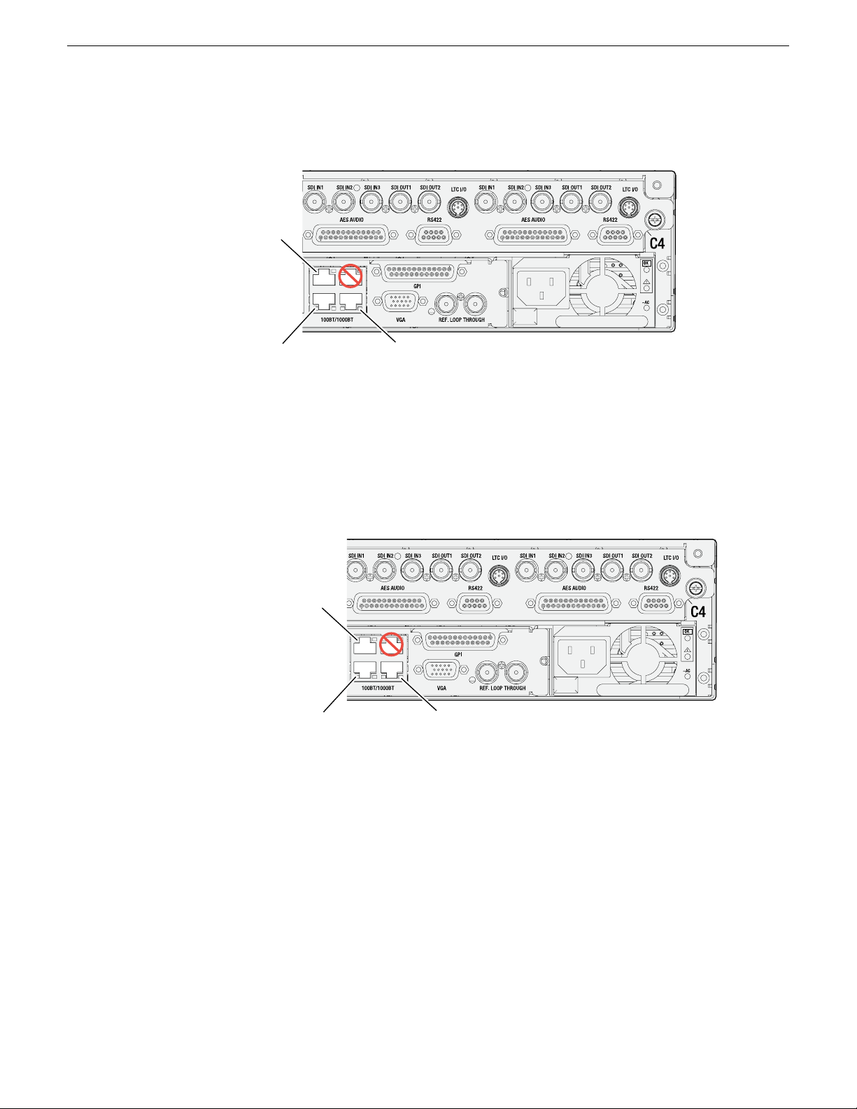
Control network Optional connection for
redundant control network
Port
1
Port2Port
3
Port
4
FTP/streaming
network
Stand-alone storage K2 Summit/Solo network connections
Control network Optional connection for
redundant control network
Port
1
Port2Port
3
Port
4
Media (iSCSI)
network
Basic shared storage (SAN) K2 Summit system network connections
System connections and conguration
On a K2 Solo Media Server, an internal storage K2 Summit system, or a direct-connect storage K2
Summit system, connect the control network to port 1, which is the rst port of the control team. If
you have a FTP/streaming network, connect that network to port 2. Port 3 is not used. In most cases
port 4, which is the second port of the control team, is not used, although it is available to provide
additional redundancy for the control network connection.
On a non-redundant shared storage (SAN) K2 Summit system, connect the control network to port
1, which is the rst port of the control team. Port 2 must be connected to the media (iSCSI) network.
Port 3 is not used. Port 4, which is the second port of the control team, is not used except as follows:
Port 4 may be used only if you extend your control network to provide the same redundancy as that
of a redundant K2 SAN.
Refer to the K2 SAN Installation and Service Manual for more information.
64 K2 System Guide 06 November 2012
Page 65

Port
1
Port2Port
3
Port
4
Media (iSCSI)
network B
Redundant shared storage (SAN) K2 Summit system network connections
Control network A
Media (iSCSI)
network A
Control network B
System connections and conguration
On a redundant shared storage (SAN) K2 Summit system, you must connect both ports of the control
team. Connect control network connection A to port 1 and control network connection B to port 4.
You must also connect both media ports. Connect port 2 to the A media network and port 3 to the
B media network. The media ports must not be teamed, as doing so interferes with failover
functionality.
Refer to the K2 SAN Installation and Service Manual for more information.
Network configuration
This section contains instructions for conguring network connections.
About network functionality
K2 networks support the following:
• Remote control and conguration of the internal storage K2 system using AppCenter from a
Control Point PC.
• Remote control of the internal storage K2 system using devices and applications software
developed for the K2 system that use industry standard remote control protocols over Ethernet.
• Stream media transfers between K2 systems and other supported Grass Valley systems. Streaming
transfers allow loading and playing a clip before the transfer is complete.
• Standard data network capability.
• General networking tasks such as le sharing and mapping network drives.
The procedures in this section guide you to relevant settings, but do not instruct you on the specic
settings required for your network. It is assumed that you understand Ethernet networks in general
and your particular network needs and that you can apply that understanding to make the required
settings using standard Windows procedures. If you need help with these procedures, contact your
network administrator.
Refer to the K2 SAN Installation and Service Manual for network conguration procedures for
06 November 2012 K2 System Guide 65
shared storage K2 clients.
Page 66

System connections and conguration
About modifying or restoring network settings
Before conguring network settings, consider the following:
• Loopback adapter — When you receive a K2 Summit Production Client, a K2 Solo Media Server,
or a K2 Media Client from the factory, it has a loopback adapter installed. The loopback adapter
allows the media le system to continue operating if an Ethernet cable is disconnected. Do not
modify the loopback adapter. If you need to restore the loopback adapter, refer to the Service
Manual for your K2 product.
The loopback IP address is 192.168.200.200. Keep that IP address reserved on your network.
Do not assign it to any other device. If this causes conicts with your existing network, consult
your Grass Valley representative.
• Hostname changes — If you change the host name, remote AppCenter and other systems could
have difculty connecting. On a shared storage K2 client, Grass Valley strongly recommends
that you do not change the host name or IP address unless following the documented procedure.
For more information, refer to the K2 SAN Installation and Service Manual.
• Restoring factory default network settings — Several settings are congured at the factory and
should never be modied. If you suspect settings have been changed, you should reimage the
K2 system to restore settings. Refer to the Service Manual for your K2 product for recovery
image and network conguration procedures.
Related Topics
Embedded Security modes and policies on page 183
Configure network settings for a stand-alone K2 systems
Stand-alone K2 systems with internal or direct-connect storage ship from the factory DHCP
congured. If your control network has DHCP/DNS and you are satised to use the factory default
host name (which is the serial number), then no local conguration of the control connection is
required.
If the Windows network settings need to be congured, you must have Windows administrator
security privileges on the K2 system.
1. Access the Windows desktop on the K2 system. You can do this locally with a connected
keyboard, mouse, and monitor or remotely via the Windows Remote Desktop Connection.
2. Open the Network Connections Control Panel.
3. Continue with standard Windows procedures to congure the TCP/IP protocol properties. You
can set up the network using DHCP, DNS, WINS, or other standard networking mechanisms.
NOTE: On small networks or networks with certain security policies a DHCP server or domain
name server (DNS) might not be available. In this case you can set up a static IP address and
create a host le on each K2 system.
66 K2 System Guide 06 November 2012
Page 67

System connections and conguration
4. Congure the control connection on the K2 system as follows:
a) Congure the network connection with the following name:
Control Team
The control team is GigE ports 1 (Control Connection #1) and 4 (Control Connection #2) on
the rear panel.
CAUTION: Under no circumstances should you modify the loopback adapter. The
loopback IP address is 192.168.200.200. Keep that IP address reserved on your network.
Don’t assign it to any other device. If this causes conicts with your existing network,
consult your Grass Valley representative.
5. Congure the FTP/streaming connection (if needed) on the K2 system.
This connection must have an IP address that is on a different subnet from the control connection.
There are special name resolution requirements for the FTP/streaming network.
Congure as follows:
a) Congure the network connection with the following name:
Media Connection #1
This is GigE port 2 on the rear panel.
6. If prompted, shutdown and restart Windows.
7. If you are going toFTP/stream videobetween K2systems, congurefor streaming video between
K2 systems; otherwise, the K2 system is ready for standard data networking tasks.
Related Topics
Embedded Security modes and policies on page 183
Streaming video between K2 systems
It is required that FTP/streaming trafc be on a separate subnet from control trafc and, in the case
of a K2 SAN with shared storage K2 clients, separate from media (iSCSI) trafc. To reserve
bandwidth and keep FTP/streaming trafc routed to dedicated ports, IP addresses for FTP/streaming
ports must have double name resolution such that hostnames are appended with the “_he0” sufx.
You can use host tables or another mechanism, such as DNS, to provide the name resolution. This
directs the streaming trafc to the correct port.
In most K2 systems, network name resolution is provided by host tables, which are found in hosts
les. The following procedure describes how to set up hosts tables to provide name resolution for
both the control network and the FTP/streaming network. If you are using other mechanisms for
name resolution, use the host table examples here to guide you. For shared storage K2 clients, also
refer to the K2 SAN Installation and Service Manual for a discussion of host tables.
Setting up the K2 system for FTP/streaming transfer has the following network requirements:
• For stand-alone internal storage K2 systems, the K2 machine is the source/destination for
FTP/streaming transfers. FTP/streaming trafc uses the FTP GigE port (Media Connection #1)
on the K2 client.
06 November 2012 K2 System Guide 67
Page 68

System connections and conguration
• For K2 Summit Production Clients or K2 Media Clients with shared storage on a K2 SAN, a K2
Media Server is the source/destination for FTP/streaming transfers. FTP/streaming trafc uses
the FTP GigE port on the K2 Media Server. No transfers go to/from the shared storage K2 client
directly.
• Some kind of name resolution process must be followed. You have the following options:
• Set up hosts les located on each networked device so that you reference host names through
the hosts les.
• Edit the DNS entries. See your network administrator.
• The host name of all peer K2 systems and Prole XP systems must be added to a Remote host
registry using the K2 AppCenter Conguration Manager.
• To import to or export from a K2 system, both the source and destination must be in the same
domain.
Set up hosts files
Set up a hosts le located in C:\WINDOWS\system32\drivers\etc\hosts on each K2 system. If
you include the names and addresses of all the systems on the network, then you can copy this
information to all the machines instead of entering it in the hosts le on each machine.
To provide the required name resolution for the FTP/streaming network, in the hosts le each system
that is a transfer source/destination has its host name listed twice: once for the control network and
once for the FTP/streaming network. The host name for the streaming network has the extension
“_he0” after the name. The K2 systems use this information to keep the FTP/streaming trafc
separate from the control trafc.
For FTP transfers to/from a K2 SAN, transfers go to/from K2 Media Servers that have the role of
FTP server. No transfers go directly to/from the shared storage K2 clients that are on the K2 SAN.
So in the hosts le, you must add the“he_0” extension to a K2 Media Server hostname andassociate
that hostname with the K2 Media Server’s FTP/streaming network IP address.
1. Open Notepad or some other text editor. When you open the text editor you must right-click and
select Run as administrator.
2. In the text editor, open the following le:
C:\WINDOWS\system32\drivers\etc\hosts
3. Enter text in two lines for each K2 system that is a transfer source/destination.
a) Type the IP address for the control network, then use the TAB key or Space bar to insert a
few spaces.
b) Type the machine name, such as K2-Client. This sets up the host le for resolving the
machine name on the control network. The machine name must not have any spaces in it.
c) On the next line, type the IP address for the FTP/streaming network, then use the TAB key
or Space bar to insert a few spaces.
d) Type the machine name followed by the characters “_he0”. Be sure to use the zero character,
not the letter ‘o’. Refer to the following example:
00.16.42.10 K2-Client
00.0.0.10 K2-Client_he0
68 K2 System Guide 06 November 2012
Page 69

4. For systems that are not a transfer source/destination, the second line (for the FTP/streaming
K2-Client
(internal storage)
Stand-alone
NewsEdit1
(not shared storage)
SAN_XP1
SAN_UIM1
K2-Client-2
(shared storage)
K2-Media Server-1
Control Point PC
10.0.0.22
Other 3rd party devices
Command/Control network
FTP/Streaming network
10.16.42.10
10.0.0.10
10.16.42.102
10.16.42.60
10.0.0.60
Note: The two media GigE ports are not used for
FTP/streaming. They are used for media (iSCSI)
networks only
10.16.42.22
10.16.42.31
10.16.42.32
10.0.0.32
10.16.42.23
K2-Client-1
(shared storage)
10.16.42.101
network) is not required.
5. If there are UIM systems on the FTP/streaming network, make sure you follow the UIM naming
conventions. Refer to the UIM Instruction Manual.
6. Once you have added the host names for the all the systems on the networks for which the host
le provides name resolution, save the le and exit the text editor.
7. Copy the hosts le onto all the other machines to save you editing it again.
8. Add host names to AppCenter to enable streaming.
Related Topics
Embedded Security modes and policies on page 183
Add host names to AppCenter to enable streaming on page 70
Sample K2 client configuration and hosts file
The following diagram illustrates one possible conguration setup, including a K2 system with
stand-alone storage, K2 clients with shared (SAN) storage, and other Grass Valley systems.
System connections and conguration
06 November 2012 K2 System Guide 69
The following example shows the contents of a default Windows hosts le with new lines added
that match the IP addresses and host names in the previous sample diagram.
Page 70

System connections and conguration
All lines beginning with a # are comments and can be ignored or deleted.
# This is a sample HOSTS file used by Microsoft TCP/IP for Windows.
#
# For example:
# 102.54.94.97 rhino.acme.com # source server
# 38.25.63.10 x.acme.com # x client host
127.0.0.1 localhost
10.16.42.10 K2-Client
10.0.0.10 K2-Client_he0
10.16.42.101 K2-Client-1
10.16.42.102 K2-Client-2
10.16.42.22 K2-MediaServer-1
10.0.0.22 K2-MediaServer-1_he0
10.16.42.23 ControlPointPC
10.16.42.60 NewsEdit1
10.0.0.60 NewsEdit1_he0
10.16.42.31 SAN_XP1
10.0.0.32 SAN_XP1_he0 SAN_UIM1_he0
10.16.42.32 SAN_UIM1
Add host names to AppCenter to enable streaming
In K2 AppCenter, you must add the host names of all peer K2 systems on the network that support
streaming transfers. Adding host names is required to allow selection of networked K2 systems in
the AppCenter user interface and to provide a successful network connection for streaming. The
host names added appear in the “Import” and “Send to” dialog boxes.
NOTE: By default, the K2 system host name is the same as the Windows operating system
computer name.
1. Open AppCenter for the K2 client.
2. In the AppCenter toolbar, select System, then choose Configuration.
3. Select the Remote tab.
The RemoteSettings dialog box displays, showing any network host names that have been added.
70 K2 System Guide 06 November 2012
Page 71

System connections and conguration
4. Select Add, to open the Add Host dialog box, then do the following:
a) Select the Host name eld, then enter the computer name of a peer K2 system.
Make sure to enter the exact computer name. Any differences will result in being unable to
connect to the K2 system.
b) If you are using VDCP remote protocol to perform video network transfers, use the following
steps to add a unique Controller ID for each host. Otherwise, you can ignore this step and
proceed to the next step.
• Select controller id eld.
• Enter the controller ID of the K2 system, then select OK. Use a number between 1 and 255
that is not assigned to any other K2 system.
c) Select OK in the Add Host dialog box.
5. Repeat the previous step for the remaining K2 systems.
6. In the Conguration dialog box, select OK to save settings.
Once the host names are added, the K2 system is ready for streaming operation. For information on
transfer compatibility and supported formats, refer to K2 system specications. For procedures on
transferring media, refer to the K2 AppCenter User Manual.
NOTE: If you have trouble, try using the ping utility in the Windows command prompt using
either the IP address or host name. Troubleshoot as needed. Also, refer to the Service Manual
for your K2 system for troubleshooting procedures.
Related Topics
Specications on page 215
Configuring Server 2008 for domain
This topic applies to Grass Valley servers with a base disk image created prior to mid-2011. Server
disk images created after that time do not require this special conguration.
Systems withthe MicrosoftWindows Server 2008 R2 operating system require special conguration.
A server must have its rewall disabled for proper K2 system operation. This includes the Windows
rewall that has different proles for workgroup, domain, etc. You must do the following steps to
disable the rewall.
1. Log in to the server with Windows administrator privileges.
06 November 2012 K2 System Guide 71
Page 72

System connections and conguration
2. From the Windows desktop click Start and in the Search programs and files box type the following
and then press Enter.
wf.msc
The Windows Firewall with Advanced Security window opens.
72 K2 System Guide 06 November 2012
Page 73

System connections and conguration
3. At the bottom of the Overview section, click Windows Firewall Properties.
The Properties dialog box opens.
4. On the Domain Profile tab, set Firewall state to Off.
5. On the Private Profile tab, set Firewall state to Off.
6. On the Public Profile tab, set Firewall state to Off.
7. Click OK to save settings and close.
Using FTP for file transfer
This section contains topics about the K2 FTP interface.
About the K2 FTP interface
The K2 FTP interface has the following modes:
• Movie mode — FTP operations are performed on assets in the K2 media database. This is the
mode ona K2 systems with a media database, suchas online/productionK2 SANsand stand-alone
K2 Summit systems.
• File mode — FTP operations are performed on les. This is the mode on systems without a
media database, such as Nearline K2 SANs.
The K2 FTP interface can run in the movie mode and the le mode simultaneously.
06 November 2012 K2 System Guide 73
Page 74

System connections and conguration
On online/production K2 SANs and stand-alone K2 Summit systems, FTP clients can log into the
K2 FTP server using credentials for Windows user accounts that are registered on the K2 system.
When such accounts are used, the K2 FTP server exposes “virtual” folders at the FTP root. A virtual
folder exists for each video le format that is supported by the FTP server. Navigation to one of
these virtual folders allows an FTP client to get or put clips in that le format.
In addition,the K2FTP serversupports reserveduser login names that directly places the FTP client
in a particular mode of operation. The login names and their modes are as follows:
movie
FTP gets/puts supported for K2 clips in the GXF le format; the clips root becomes
the FTP root.
mxfmovie
FTP gets/putssupported for K2 clips in the MXF le format; the clips root becomes
the FTP root
mpgmovie
FTP putssupported for MPEG program and transport streams; the clips root becomes
the FTP root
video_fs
k2vfs
Pinnacle FTP emulation mode
All FTPoperations supported on generic les on the K2 system's media le system;
media le system root becomes the FTP root
You can use Internet Explorer to access the FTP interface to see an example.
The K2 FTP server runs on K2 Media Server that has the role of FTP server. While it also runs on
the K2 Solo Media Server, stand-alone storage K2 Summit Production Clients and K2 Media Clients,
it is important to understand that it does not run on shared storage K2 clients. When you FTP les
to/from a K2 SAN, you use the FTP server on the K2 MediaServer, not on the K2 client that accesses
the shared storage on the K2 SAN.
If clips are created by record or streaming on a K2 le system such that media les have holes/gaps,
i.e. unallocated disk blocks, in them, then that clip represents a corrupt movie that needs to be
re-acquired. The K2 system handles corrupt movies of this type on a best-effort basis. There is no
guarantee that all available media, especially media around the edges of the holes/gaps, is streamed.
You can also apply K2 security features to FTP access.
When using FTP in a shared storage environment, ensure that all FTP communication takes place
on the FTP/streaming network, and not on the Control network.
Related Topics
FTP access by Internet Explorer on page 78
FTP and media access security on page 179
FTP and media access security on page 76
Importing via Pinnacle emulation K2 FTP on page 119
Limitations with complex media types
Depending on the system software versions of source and destination devices, it is possible that lists
or programs made from lists that contain movies with mixed video compression types or mixed
74 K2 System Guide 06 November 2012
Page 75

audio types cannot stream to other devices, nor can they be exported to a le. Refer to release notes
for the specic software versions for details.
MXF OP1A supports transfer of simple media types only, which are a subset of the K2
encode/decode/metadata capabilities. For example, MXF OP1A does not support the transfer of
complex clips, such as a subclip that spans two media les. Do not attempt MXF OP1A transfers
of complex clips.
Transferring between different types of systems
While GXF transfer of media with mixed format (such as an agile playlist) is supported between
K2 systems, it might not be supported between a K2 system and a non-K2 system, depending on
system software versions. Refer to the release notes for the software version.
You can also use remote control protocols to initiate transfers.
Related Topics
Remote control protocols on page 209
Specications on page 215
System connections and conguration
Transfer mechanisms
You can move material between systems using the following mechanisms, each of which offers a
different set of features:
• Manual mechanisms — These are the AppCenter transfer features. Refer to the K2 AppCenter
User Manual for AppCenter instructions. When transferring between K2 systems you can browse
and select les for transfer. When transferring between K2 systems and other types of systems,
one or more of the following might be required, depending on software versions. Refer to release
notes for the version information:
• Specify the IP address, path, and le name to initiate a transfer.
• Add the remote host in Conguration Manager before the transfer.
• Enter machine names in compliance with UIM naming conventions.
• Automatic mechanisms, including the following:
• K2 FTP interface — This interface supports transfers via third party FTP applications, such
as automation systems. To demonstrate this, you can use Internet Explorer to transfer les
between a PC and the FTP interface on a stand-alone K2 Summit Production Client or a K2
Media Server on the same network.
• Remote control protocols — Industry standard remote control automation applications can
initiate transfers. The protocol command must be sent to the K2 client. This applies to both
stand-alone and shared storage K2 systems.
Related Topics
Remote control protocols on page 209
FTP access by automation on page 76
06 November 2012 K2 System Guide 75
Page 76

System connections and conguration
FTP access and configuration
For basic LAN access, the following Grass Valley products can connect as an FTP client to the K2
FTP server with no special conguration required:
• K2 Summit Production Client
• K2 Media Client
• K2 Solo Media Server
• UIM-connected Prole XP Media Platform
For WAN access, contact your Grass Valley representative for assistance.
If the FTP client is not one of these Grass Valley products, contact the product’s supplier or your
network system administrator for assistance with conguring TCP window scaling. Any computer
that connects as an FTP client to the K2 FTP server must have TCP window scaling enabled. Refer
to http://support.microsoft.com/kb/q224829/ for more information on this feature. Never set
Tcp1323Opts without setting TcpWindowSize. Also, Windows NT 4.0 does not support TCP window
scaling, but will still communicate with Grass Valley products in a LAN environment.
FTP access by automation
Using FTP, third parties can initiate transfers between two K2 systems or between a K2 system and
another FTP server. Transfers of this type are known as “passive” FTP transfers, or “server to server”
transfers.
If you are managing transfers with this scheme from a Windows operating system computer, you
should disable the Windows rewall on that computer. Otherwise, FTP transfers can fail because
the Windows rewall detects FTP commands and can switch the IP addresses in the commands.
NOTE: You should disable the Windows rewall on non-K2 systems issuing passive FTP transfer
commands.
FTP and media access security
The following systems host the K2 FTP interface:
• A stand-alone K2 system.
• A K2 Media Server that takes the role of FTP server
The way in which the K2 FTP interface applies media access security is explained in this section.
The K2 FTP interface uses the credential information for the current FTP session logon and checks
it against the access control list for a K2 bin. This is the access control list that you set up through
the Organize Bins dialog box in AppCenter. Any media access related operations such as get, put,
dir, rename and delete are checked against the FTP session’s logon credentials to access the media.
For example, if an FTP session is denied access to List Bin Contents for bin A, then the session can
not initiate a dir operation on bin A to list the contents of the bin. Furthermore, the session can not
transfer clips into bin A using the put operation.
For the purpose of compatibility FTP accessconventions, accounts for user movieor user mxfmovie
are provided on the K2 system. There is also a video_fs account for Mac/FCP access. These accounts
76 K2 System Guide 06 November 2012
Page 77

are automatically set up when you install K2 software version 3.2 or higher. Do not restrict access
for these accounts. If your security policy requires restrictingaccess to these accounts, contact Grass
Valley Support.
On a K2 SAN, authentication takes place on the K2 Media Server. Setting up FTP security for
specic local users and groups is not supported on a K2 SAN, with the exception of the local movie
and mxfmovie accounts. However, you can set up FTP security for domain users and groups.
About FTP internationalization
The K2 FTP interface supports clip and bin names in non-English locales (international languages)
as follows:
• Non-ASCII localized characters represented as UTF-8 characters.
• All FTP client/server commands are in ASCII.
• The named movie asset is Unicode 16-bit characters
• The K2 FTP client converts between Unicode and UTF-8 strings explicitly.
Also refer to “Internationalization” on page 210.
System connections and conguration
The Microsoft FTP client does not convert from a Unicode string to a UTF-8 string. Instead, it passes
the Unicode string to the FTP server directly, which can cause errors. To avoid these errors, in the
FTP command, every reference to the clip path must be in UTF-8.
A specic language setting is required on the computer that hosts the K2 FTP interface. This
requirement applies to a K2 Media Server, K2 Solo Media Server, and a stand-alone K2 client, as
they all host the K2 FTP interface.
Related Topics
Internationalization on page 240
06 November 2012 K2 System Guide 77
Page 78

System connections and conguration
Setting the FTP language
1. Open the Regional and Language control panel.
2. On the Administrative tab make sure “Current language for non-Unicode programs” is set to
English (United States).
3. If you made a change click Apply and OK, and when prompted restart the computer to put the
change into effect.
Related Topics
Embedded Security modes and policies on page 183
FTP access by Internet Explorer
You can use Internet Explorer to transfer les via FTP between a PC and the FTP interface on a
stand-alone K2 system or a K2 Media Server, so long as both source and destination machines are
on the same network.
While the K2 FTP interface supports local languages, some international characters are not displayed
correctly in Internet Explorer. Use only English language characters with Internet Explorer.
78 K2 System Guide 06 November 2012
Page 79

System connections and conguration
To access FTP using Internet Explorer, use the following syntax in the Address eld:
ftp://<username:password@hostname>. The username/password can be any account set up
on the machine hosting the FTP interface. The hostname can be the name of a stand-alone K2 client
or it can be the name of a K2 Media Server. (You cannot make a FTP connection to a K2 client with
shared storage or to a K2 Control Point PC.)
Once you have logged in, the two virtual directories are displayed.
GXF —General ExchangeFormat (SMPTE 360M). This is the standard Grass Valley le interchange
format. Refer to specications later in this manual for media types supported.
MXF — Media Exchange Format (SMPTE 377M). Refer to specications later in this manual for
media types supported.
Inside the GXF and MXF folders you can see contents of the system.
06 November 2012 K2 System Guide 79
Page 80

System connections and conguration
The subfolders are organized in typical Windows fashion, with columns denoting the le’s name,
size, etc. The Size column refers to the clip duration (in video elds).
You can use Internet Explorer to drag a le from your stand-alone K2 system or K2 Media Server
and drop it in a folder on your PC. You can also drag a le from your PC and drop it in the appropriate
folder on your stand-alone K2 system or K2 Media Server.
Be careful not to mix les from the two types of le interchange formats. GXF les can only be
transferred to the GXF folder, and MXF les can only be transferred to the MXF folder. If you try
to drop a clip into the incorrect folder, the transfer fails. For example, clip1.gxf can be dropped
into the K2-MediaSVR/GXF/default/ folder, but notinto the K2-MediaSVR/MXF/default/ folder.
Related Topics
FTP and media access security on page 76
FTP commands supported
The following table lists the FTP commands that the K2 FTP interface supports.
K2 FTP supportFTP command descriptionFTP command name
SupportedUser NameUSER
SupportedPasswordPASS
Not supportedAccountACCT
SupportedChange working directoryCWD
SupportedChange to parent directoryCDUP
Not supportedStructure mountSMNT
Not supportedReinitializeREIN
SupportedLogoutQUIT
SupportedData portPORT
80 K2 System Guide 06 November 2012
Page 81

System connections and conguration
K2 FTP supportFTP command descriptionFTP command name
SupportedPassivePASV
SupportedRepresentation typeTYPE
Not supportedFile structureSTRU
Not supportedTransfer modeMODE
SupportedRetrieveRETR
SupportedStoreSTOR
Not supportedStore uniqueSTOU
Not supportedAppend (with create)APPE
Not supportedAllocateALLO
Not supportedRestartREST
SupportedRename FromRNFR
SupportedRename ToRNTO
Using FTP on a K2 Nearline SAN
SupportedAbortABOR
SupportedDeleteDELE
SupportedRemove directoryRMD
SupportedMake directoryMKD
SupportedPrint working directoryPWD
ListLIST
Supported. Reports size in
number of video elds.
SupportedName ListNLST
SupportedSite ParametersSITE
SupportedSystemSYST
Size of le (clip)SIZE
Supported. Reports size in
Bytes.
SupportedStatusSTAT
SupportedHelpHELP
SupportedNo OperationNOOP
A K2 Nearline SAN is considered an “ofine” system,as it has no media database and is notcapable
of direct playout of media. On this type of system the K2 FTP interface operates in le mode.
Therefore, procedures that apply to “online” K2 SANs do not globally apply to the Nearline SAN.
This includes procedures for streaming, import, export, and FTP.
06 November 2012 K2 System Guide 81
Page 82

System connections and conguration
The rules for transferring to/from a K2 Nearline SAN are as follows:
• Transfer les only. Streaming media, as in AppCenter’s Import/Send to | Stream feature, is not
supported.
• K2 media must be transferred to/from the Nearline system as a GXF or MXF le.
• Passive FTP mode is supported. You must use this mode for FTP transfers.
• In addition to FTP transfers, you can also map shared drives and use basic Windows networking
to move les to/from a Nearline storage system.
• You should use the dedicated K2 FTP/streaming network.
Additional information about Nearline FTP is as follows:
• K2 FTP protocol supports clip and bin names in non-English locales (international languages)
using UTF-8 character encoding. Refer to specications for internationalization.
• The Nearline FTP interface operates in le mode so it does not have GXF and MXF folders to
support format-specic functionality, as does the K2 FTP interface in movie mode for “online”
K2 systems. This means the Nearline FTP interface treats all les, including GXF and MXF, as
generic les with no particular consideration for any le format.
Using reference files
When you create a simple K2 clip on a K2 system, K2 softwarecan create a corresponding reference
le. The reference le is stored in a directory in the clip's folder on the V: drive. You can congure
the software to create QuickTime reference les, MXF reference les, or no reference les. The
following topics provide information about reference les on K2 systems.
About QuickTime reference files
The following formats are supported as QuickTime reference les:
• DV
• AVC-Intra
• XDCAM-EX
• XDCAM-HD
• XDCAM-HD 422
• IMX
The K2 clip must be a simple clip in order to create the reference le. With the QuickTime reference
le you can open the K2 clip with QuickTime tools, such as Final Cut Pro, for playback and editing.
For some formats the QuickTime tool does not provide default support, so you must congure the
tool as necessary to support the format. The QuickTime tool must be run on another system. Running
the QuickTime player or other QuickTime tools on the K2 system is not supported. You haveoptions
for connections, access, and software to support your workow requirements.
About MXF reference files
For MXF reference les, the K2 clip can be any supported format simple clip. K2 software creates
the MXF reference le when you create a new simple clip by recording, importing, or copying. K2
82 K2 System Guide 06 November 2012
Page 83

System connections and conguration
software does not create the MXF reference le when you create a playlist, a program with
continuous-recorded material, or a clip with tracks having a duration less than the clip duration. The
reference le is a MXF OP1b le with external essence. The reference le gives you options for
connections, access, and software to support your workow requirements.
Configuring reference file type on a standalone K2 Summit/Solo system
1. In AppCenter, click File | System | Configuration.
Conguration Manager opens.
2. In Conguration Manager, click the System tab.
3. In Reference Files settings, for the Reference file type setting, select one of the following:
• None — K2 software does not create reference les.
• QuickTime — K2 software creates QuickTime reference les.
• MXF — K2 software creates MXF reference les.
4. Click OK to apply the setting.
5. Restart the standalone K2 Summit/Solo system to put the change into effect.
Configuring reference file type on a K2 SAN system
1. In the K2Cong application, for the K2 Media Server with role of le system server, access the
File System Server Conguration page as follows:
• On a SAN that is already congured, in the tree view click File System Server.
• On a SAN that is not yet fully congured, work through the Congure K2 Server wizard until
you reach the File System Server Conguration page.
2. On the File System Server Conguration page select one of the following:
• No reference le — K2 software does not create reference les.
• QuickTime reference le — K2 software creates QuickTime reference les.
• MXF reference le — K2 software creates MXF reference les.
3. Click Check to apply the setting.
4. Manage the required K2 Media Server restart as follows:
• On a SAN that is already congured, you must restart the K2 Media Server to put the change
into effect. Follow the restart procedure appropriate for the basic or redundant K2 SAN.
• On a SAN that is not yet fully congured, continue to work through the Congure K2 Server
wizard. The restart at the end of the conguration process is sufcient.
If a redundant K2 SAN, you must congure similarly and restart both K2 Media Servers with role
of le system server.
06 November 2012 K2 System Guide 83
Page 84

System connections and conguration
Quicktime and Final Cut Pro support
You can access K2 media as QuickTime for editing in Final Cut Pro, as explained in the following
topics.
About connecting to K2 storage with Final Cut Pro
This topic describes the different ways you can access K2 media for editing with Final Cut Pro.
Connection types are as follows:
• Fibre Channel – This is a connection as a client to a Fibre Channel K2 SAN. The connection
requires a K2 FCP Connect license and supporting software on the Macintosh system. The
connection uses the K2 SAN's Fibre Channel network.
• iSCSI – This is a connection as a client to an iSCSI K2 SAN. The connection requires a K2 FCP
Connect license and supporting software on the Macintosh system. The connection uses the K2
SAN's iSCSI Gigabit Ethernet network.
• CIFS – This is a basic CIFS connection. You can access les on K2 SAN storage or K2
stand-alone storage with this type of connection. The connection uses a basic Ethernet network.
Access methods are as follows:
• Edit-in-place – With this method you edit the K2 media in Final Cut Pro across the network
while the media is still in place in K2 storage. You can do this over any connection type.
• File transfer – With this method you transfer (copy) the K2 media to the Macintosh system and
then edit it in Final Cut Pro across the network while the media is still in place in K2 storage.
You can do this over any connection type. You can initiate the transfer as le copy over Fibre
Channel, le copy over iSCSI, le copy over CIFS, or via FTP.
With all access methods, after you are done editing the K2 media you export it back to K2 storage
via a K2 HotBin.
Software components that support various workows are as follows:
• K2 FCP Connect – This is a Grass Valley product that supports all connection types for optimal
performance. It is a toolset that must be purchased, installed, licensed, and congured. It includes
GV Connect, which is a Final Cut Pro plug-in. GV Connect supports edit-in-place and le transfer
over Fibre Channel, iSCSI, or CIFS connections. It also includes GV Browse, which supports
searching for QuickTime reference les on a MediaFrame server and transferring them to Final
Cut Pro for editing.
• Flip4Mac – This is a Telestream product that supports FTP le transfer of K2 media to the
Macintosh system. It is a Final Cut Pro plug-in.
Connections, access, and software apply to K2 storage and versions as follows:
SoftwareAccess methodConnection typeK2 storage/version
File transferCIFSK2 SAN and stand-alone K2 Media
Client software version 3.3.2.1374 and
higher
84 K2 System Guide 06 November 2012
Flip4Mac
recommended
Page 85

System connections and conguration
SoftwareAccess methodConnection typeK2 storage/version
AllCIFSStand-alone K2 Media Client software
version 3.3.2.1374 and higher, and
K2 FCP Connect
recommended
stand-alone K2 Summit Production
Client software version 7.2.7.1397 and
higher
AllAllK2 SAN (K2 Media Client) software
version 3.3 and higher, and K2 SAN
(K2 Summit Production Client)
software version7.2.7.1397 and higher
K2 FCP Connect
recommended for
CIFS, required for
iSCSI and Fibre
Channel SAN.
For detailed instructions refer to documentation as follows:
• Fibre Channel, iSCSI, or CIFS connection with K2 FCP Connect – Refer to the K2 FCP Connect
documentation set, which includes the following documents:
• K2 FCP Connect Installation Manual
• K2 FCP Connect Release Notes
• GV Connect User Manual
• GV Browse User Manual
• Basic CIFS connection without K2 FCP Connect – Refer to topics later in this manual.
Related Topics
About QuickTime reference les on page 82
Install and configure Macintosh Final Cut Pro systems on K2 storage
Read the following topics to get systems connected and media access operational.
Final Cut Pro CIFS mount to K2 storage quick start installation checklist
Use the following sequence of tasks to set up Final Cut Pro access to K2 storage via CIFS mount
without a K2 FCP Connect license. This applies to the following K2 systems:
• K2 SAN and stand-alone K2 Media Client software version 3.2 and higher
• K2 SAN and stand-alone K2 Summit Production Client software version 7.1 and higher
This checklistassumes thatthe K2 system has been installed/commissionedand is fully operational.
On the K2 system
CommentInstructionsTask
Congure hosts les on the K2
system
Add Macintosh systems
to the K2 hosts le
Enter MacintoshIP addressand
name in hosts les.
06 November 2012 K2 System Guide 85
Page 86

System connections and conguration
CommentInstructionsTask
Create a Macintosh user
account. This is the account
that theMacintosh system uses
to log on to the K2 system.
Optional: Enable Access
Control Lists, if desired.
Share V: drive as
default/gvfs_hostname.
On all Macintosh client computers
Install Final Cut Pro, if not
already installed.
Install Flip4Mac, if necessary
for your workow.
Cable network connections.
Use standard Windows
operating system
procedures.
Topic "Enable Access
Control Lists on the K2
system"
Use standard Windows
operating system
procedures. Set
permissions to read only.
documentation
documentation
Connect the Macintosh
system to the K2
system's control
network.
This is not necessary if the
Macintosh system logs on with
the default administrator
account.
This is optional. If you do this
task, you must also congure
Active Directory Domain on
the Macintosh systems.
On a K2 SAN, create the share
on the primary K2 Media
Server. Do not create the share
on a SAN connected K2 client.
CommentInstructionsTask
—Final Cut Pro
This software is optionalFlip4Mac
Only the control network
connection is necessary.
Congure for control
network, if not already done.
Optional: Congure Active
Directory Domain
Mount the K2 system's
volume default.
Final tasks
If used, verify Access Control
Lists.
If desired,congure HotBinon
the K2 system to receive
nished Final Cut Pro les.
Macintosh systems for
control network"
Topic "Congure
Macintosh systems for
Active Directory
Domain"
Topic "Connecting via
SAMBA/CIFS"
Control Lists"
HotBin" and "About
QuickTime import delay"
—Topic "Congure
This is optional. If you do this task,
you must also enable Access
Control Lists on the K2 system.
In the Name eld, enter
<K2_name>/<username>.
CommentInstructionsTask
—Topic "Verify Access
—Topics "Congure
86 K2 System Guide 06 November 2012
Page 87

Enable Access Control Lists on the K2 system
Prerequisites for the K2 system are as follows:
• Current compatible versions of the Windows operating system and SNFS software.
• Standard C:, D:, E: and V: disk volumes.
• SNFS has been congured with Grass Valley's Storage Utility.
• The SNFS conguration le is located in the D:\SNFS\config\ directory.
If desired, you can enable Access Control Lists (ACLs). For SAN access enable ACLs on the K2
Media Server(s). For stand-alone K2 storage access enable ACLs on the stand-alone K2 system. If
you do this task, you must also congure Active Directory Domain on the Macintosh systems.
1. If a redundant K2 SAN, take FSM K2 Media Servers out of service and manage redundancy as
directed in documented procedures.
2. Navigate to D:\SNFS\config\ and open the SNFS conguration le in a text editor. The le is
named either default.cfg or gvfs_hostname.cfg where hostname is the name of the K2
system—if a redundant SAN, the name of the primary FSM.
3. Conrm/enter/modify text lines as necessary to congure as follows:
System connections and conguration
WindowsSecurity Yes
EnforceACLs Yes
UnixIdFabricationOnWindows Yes
UnixDirectoryCreationModeOnWindows 0700
UnixFileCreationModeOnWindows 0600
UnixNobodyGidOnWindows 60001
UnixNobodyUidOnWindows 60001
Avoid duplicate settings.
NOTE: Once ACLs are enabled on the K2 system (WindowsSecurity set to Yes), they cannot
be disabled.
4. Save the SNFS conguration le.
5. Restart the K2 system.
6. If a redundant K2 SAN, repeat these steps on the redundant FSM K2 Media Server.
7. After restart of K2 Media Server(s) is complete, restart all clients of the K2 SAN.
Configure Macintosh systems for control network
Depending on the version of your Macintosh operating system, the steps in this task can vary. Refer
to your Macintosh documentation as necessary.
Congure each Macintosh system as follows:
1. Open System Preferences, Network settings.
2. Set Ethernet 1 to congure manually (static IP).
3. Congure IP address, subnet mask, and other settings as required for the control network.
Configure Macintosh systems for Domain
Depending on the version of your Macintosh operating system, the steps in this task can vary. Refer
to your Macintosh documentation as necessary.
06 November 2012 K2 System Guide 87
Page 88

System connections and conguration
If desired, MAC OS X can be congured to use Active Directory (AD) resources such as users and
groups. Once a computer is bound to an AD domain, users belonging to that domain may login to
the Macintosh system at the main login prompt. If you do this task, you must also enable Access
Control Lists on the K2 storage you access, either the K2 Media Server (FSM) for SAN access or
the stand-alone K2 system.
1. Open System Preferences and click Accounts.
2. If the Lock icon is locked, unlock it by clicking it and entering the administrator name and
password.
3. Click Login Options, then click Join or Edit. If you see an Edit button, your computer has at least
one connection to a directory server.
4. Click the Add (+) button.
5. From the "Add a new directory of type" pop-up menu, choose Active Directory.
6. Fill in the Active Directory information for the domain administrator account.
The administrator account is only needed at the time of binding. Once the computer is bound to
a domain, all users of the domain can be used to log in to the Macintosh system.
7. Click OK.
The Macintosh computer goes through the binding process. If successful, the domain name is
listed with the status message, "This server is responding normally".
8. Click Open Directory Utility or, if desired, click Done and open the Directory Utility from the
System/Library/Core Services folder.
88 K2 System Guide 06 November 2012
Page 89

System connections and conguration
9. Click Services.
10. Verify that the Active Directory option is checked.
If you need to change options, rst double-click the Lock icon on the lower left hand corner and
authenticate as administrator.
06 November 2012 K2 System Guide 89
Page 90

System connections and conguration
11. If desired, add AD accounts or groups as administrators of the Macintosh computer as follows:
a) In the Services tab, double-click on the Active Directory name.
b) Open the advanced options and click on the Administrative tab.
c) Verify that the Prefer this domain server and Allow administration by check boxes are checked.
d) Add any AD user or group of the domain to the list.
You must type the user or group name, then a backslash, before the domain name.
Connecting via SAMBA/CIFS
Depending on the version of your Macintosh operating system, the steps in this task can vary. Refer
to your Macintosh documentation as necessary.
90 K2 System Guide 06 November 2012
Page 91

System connections and conguration
Use this method to connect to the SNFS volume via CIFS. Once the Macintosh computer has been
bound to a domain it can then connect to any domain controlled, shared volume via SAMBA. If
connecting via SAMBA, XSan software does not need to be installed or congured.
1. On the Macintosh computer open the Finder program and at the top menu click Go | Connect to
Server.
The Connect to Server dialog box opens.
2. In the Server Address eld, type smb://, then type the IP or DNS name of the server to which
you are connecting, slash, then type the volume name.
06 November 2012 K2 System Guide 91
Page 92

System connections and conguration
3. Click Connect.
You are prompted to authenticate.
In the Name eld, makesure you enter the name of theK2 system (shown here as "yourdomain"),
then a backslash, then the username.
The volume should be mounted in the /Volumes directory and viewable in the Finder program.
Rights to les and folders are enforced based on the security prole of the user you authenticated
with when connecting with SAMBA, not the user you are logged in as on the Macintosh computer.
Verify Access Control Lists on a Macintosh system
Verify the following before you begin:
• Two domain users
• A correctly congured K2 system
92 K2 System Guide 06 November 2012
Page 93

System connections and conguration
• At least one Macintosh system attached
If you are using Access Control Lists on Macintosh OS X and the Windows operating system, use
this task to verify.
1. Test permissions on the K2 system as follows. For K2 SAN access, test permissions on the
primary K2 Media Server FSM. For stand-alone K2 storage access, test permissions on the
stand-alone K2 system.
a) Create a new text le on the V: drive.
b) Right-click on the text le and select Properties.
c) Click the Permissions tab.
d) Select Everyone and then for the Write permission select the Deny check box.
e) Create a folder on the V: drive.
f) Give full permissions to the rst user (designated in this procedure as userA) on the domain.
g) Give read only permissions to the second user (designated in this procedure as userB) on the
domain.
06 November 2012 K2 System Guide 93
Page 94

System connections and conguration
2. On the Macintosh system, do the following:
a) Login as userA.
b) Right-click on the text le and select Properties.
c) Open up Terminal and change directory to the volume.
If the SNFS le system is named "default" type the following and press Enter:
cd /Volumes/default
If the SNFS le system is named "gvfs_hostname" (where hostname is the name of the K2
system) type the following and press Enter:
cd /Volumes/gvfs_hostname
d) Type the following command:
ls –le
e) Verify that there is a "+" next the text le, plus a list of permissions below. If this is true then
cross-platform ACLs are enabled.
f) Open the Finder, go to the default volume and try to edit the text le. This should fail as the
le should not be writeable.
g) In the Finder, go to the folder you created earlier in this procedure and create a text le in the
folder. This operation should be successful.
h) Log out and then log back in as userB.
i) In the Finder, go to the folder you created earlier in this procedure and try to create a text le
in the folder. This operation should fail.
94 K2 System Guide 06 November 2012
Page 95

Configure HotBin
If a K2 SAN, the SNFS conguration le must have settings as follows:
• If Windows Security is No, GlobalSuperUser must be set to Yes.
• If Windows Security is Yes, no GlobalSuperUser setting is required.
Congure a HotBin on the K2 system to receive the nished media from Final Cut Pro.
1. In K2 AppCenter, create a bin with an appropriate name, such as "dstBin".
2. Congure dstBin as a HotBin.
Refer to the K2 System Guide for instructions.
3. When you congure a HotBin, in the Capture Services Utility you can adjust QuickTime Import
Delay. The recommended setting is 15 seconds. Refer to the next topic for more information.
About QuickTime import delay
When you copy a le into a K2 HotBin, the HotBin watches for the le to close and the copy
operation to stop, which should indicate the le is complete, before it begins to import the le into
K2 storage. However, Final Cut Pro repeatedly opens and closes any QuickTime le as it exports
the le, so it is possible that the K2 HotBin can detect a le closed event and begin to import the
le before Final Cut Pro is done. If this occurs, the K2 HotBin import for that le fails.
System connections and conguration
To avoid this problem, when you congure a K2 HotBin you can congure the QuickTime import
delay setting. This setting allows you to adjust how long a QuickTime le must be idle (no data
being written to the le) before the HotBin begins to import the le into K2 storage. The
recommended default value is 15 seconds. If you have problems with failed imports and you suspect
that Final Cut Pro is holding on to the le with pauses longer than 15 seconds, you should increase
the QuickTime import delaytime and re-try the import. The HotBin process constrains the QuickTime
import delay range to between 10 and 60 seconds.
Using Final Cut Pro on a K2 storage
Read the following topics to use access and edit K2 media with Final Cut Pro.
Operation guidelines
Take the following into consideration as you use Final Cut Pro on K2 storage.
• Do not use the K2 AppCenter "Erase Unused Media" operation on clips that you are accessing
on K2 storage.
Media access
1. From the Macintosh systemon which you are running FinalCut Pro, access K2 media as follows:
• If your access method is le transfer via Flip4Mac (FTP), in Final Cut Pro click File | Import
| Grass Valley....
• If your access method is le transfer via direct le copy, open the Macintosh Finder.
• If your access method is edit-in-place, in Final Cut Pro click File | Open.
06 November 2012 K2 System Guide 95
Page 96

System connections and conguration
2. Browse to the location of the media in your K2 bin structure.
The QuickTime reference path/le is named according to the convention \<bin name>\<clip
name>\<clip name>.mov.
If accessing media on a K2 version 7.x system, all the les associated with the clip are in the
\<bin name>\<clip name> directory.
3. Do one of the following:
• If your access method is le transfer via Flip4Mac (FTP), transfer the QuickTime reference
le to the local Macintosh system, then open the le in Final Cut Pro and Save As to the
location of your work in progress.
• If your access method is le transfer via direct le copy, copy all the les associated with
the clip to the local Macintosh system, then open the QuickTime reference le in Final Cut
Pro and Save As to the location of your work in progress.
• If your access method is edit-in-place, open the QuickTime reference le in Final Cut Pro.
4. Edit the le as desired.
5. When you have nished material that you have created in Final Cut Pro, export it to the K2
system.
Export to K2 storage
When exporting media to K2 storage, Final Cut Pro export options must be constrained so that the
resulting media is playable on a K2. The exported media must match the frame rate of movies
supported on the K2 system. This is especially important in XDCAM where there are 25, 29.97/30,
50 and 59.94/60 rates.
1. Create the Final Cut Pro clip with a single track of video.
2. Save the Final Cut Pro clip with a .mov extension.
3. Use the Final Cut Pro "Using QuickTime Conversion" method to export the Final Cut Pro clip
as a stream movie to the K2 HotBin.
Make sure the frame rate is supported on the K2 system.
For material originally recorded on a K2 system, supported frame rates are as follows:
• If you are exporting 1080i material the frame rate must be "Current" or 60 (50 for PAL).
• If you are exporting 720p material the frame rate must be "Current" or 60.
• If you are exporting 720p material for 1080i conversions the frame rate must be 60 (50 for
PAL).
The HotBin imports the clip into the K2 system as K2 media. As a by-product of the import, the K2
system creates a QuickTime reference le for the new K2 media.
Connecting RS-422 K2 Summit/Solo 3G system
You can control the K2 system with remote control devices and software developed for the K2
system thatuse industry-standardserial protocols: AMP, BVW, and VDCP. Make RS-422connections
for protocol control as illustrated:
96 K2 System Guide 06 November 2012
Page 97

!
OK
~AC
C1 C2 C3 C4
USB/1394
100BT/1000BT
GPI
VGA
REF.LOOP THROUGH
!
OK
~AC
Channel 1
RS-422
Channel 2
RS-422
Channel 3
RS-422
Channel 4
RS-422
Refer to topics in "K2 AppCenter User Manual" to congure the K2 system for remote control.
Channel 1
RS-422
Channel 2
RS-422
Channel 3
RS-422
Channel 4
RS-422
!
OK
~AC
C1 C2 C3 C4
USB/1394
100BT/1000BT
GPI
VGA
REF.LOOP THROUGH
!
OK
~AC
GPI in/out
Connecting RS-422 first generation Summit
You can control the K2 system with remote control devices and software developed for the K2
system thatuse industry-standardserial protocols: AMP, BVW, and VDCP. Make RS-422connections
for protocol control as illustrated:
System connections and conguration
Refer to the K2 AppCenter User Manual to congure the K2 system for remote control.
Related Topics
Remote control protocols on page 209
RS-422 protocol control connections on page 213
Connecting GPI
The K2 Summit/Solo system provides 12 GPI inputs, and 12 GPI outputs on a single DB-25 rear
panel connector, as illustrated:
K2 Summit 3G system shown. Connection is identical on rst generation K2 Summit/Solo system.
06 November 2012 K2 System Guide 97
Page 98

System connections and conguration
Refer to topics in "K2 AppCenter User Manual" for GPI conguration procedures.
Related Topics
GPI I/O specications on page 223
GPI I/O connector pinouts on page 265
98 K2 System Guide 06 November 2012
Page 99

Chapter 4
Import/export services
This section contains the following topics:
• Using the HotBin capture service
• Using the XML Import capture service
• Using the P2 capture service
• Using the Export capture service
• Licensing K2 capture service software
• PitchBlue workow considerations
• Pinnacle support
• Compressed VBI import
06 November 2012 K2 System Guide 99
Page 100

Import/export services
Using the HotBin capture service
This section contains topics about the K2 HotBin Import capture service.
About the HotBin capture service
The functionality of the HotBin service is provided by the Grass Valley Import Service. The HotBin
service provides a way to automate the import of les as clips into the K2 media le system and
database. This is similar to what happens when you manually import les one at a time using K2
AppCenter import features, except with the HotBin service the les are automatically imported.
The HotBin service can import any le or stream type that is supported as a K2 le-based import.
By default,the service does not start automatically. If you have never congured orused the service,
it is set to startup type Manual. When you congure the service for the rst time, the service is set
to startup type Automatic. However, if you upgrade or otherwise re-install your K2 System Software,
the service is re-set to startup type Manual. Therefore, you must re-congure the service after K2
System Software upgrade/reinstall in order to set the startup type back to Automatic.
There is no Grass Valley license required specically for the HotBin service.
Before you can use the HotBin service, it must be congured through the K2 Capture Services
utility. The HotBin service must be congured on the K2 system that receives the imported media.
The K2 system that receives the imported media can be a K2 Solo Media Server, a stand-alone K2
Summit Production Client, a stand-alone K2 Media Client, or the K2 Media Server with the role of
primary FTP server on a K2 SAN.
Once congured, the HotBin service monitors a watched folder (a HotBin). The watched folder is
a specied source directory on a source PC. The watched folder can be on a stand-alone K2 system,
a K2 Media Server, a Windows PC, or a Macintosh. When les are placed in the watched folder,
the HotBin service imports them as a clip into the specied destination bin. The destination bin is
on the K2 system that receives the imported media and is within that K2 system’s media le system
and database.
The HotBin service automatically creates sub-directories in the watched folder (source directory),
described as follows:
• Success — After the HotBin service successfully imports the les in the source directory into
the destination bin on the K2 system, it then moves those les into the Success directory.
• Fail — If the HotBin service can not successfully import the les in the source directory into the
destination bin on the K2 system, it moves the failed les into the Fail directory.
• Archive — If there are les in the source directory when the Hot Bin service rst starts up, it
does not attempt to import those les into the K2 system. Instead, it moves those les into the
Archive directory. This occurs when you rst congure the Hot Bin service, if you manually
stop/start the Hot Bin service, and when you upgrade K2 system software.
Related Topics
Specications on page 215
100 K2 System Guide 06 November 2012
 Loading...