

Page 1
K2
Summit 3G Production Client
Service Manual
071-8725-02
February 2012
Page 2

Affiliate with the N.V. KEMA in The Netherlands
CERTIFICATE
Certificate Number: 510040.001
The Quality System of:
Thomson Inc, and its worLdwide Grass Valley division affiliates DBA
GRASS VALLEY
Headquarters
400 Providence Mine Rd
Nevada City, CA 95959
United States
15655 SW Greystone Ct.
Beaverton, OR 97006
United States
10 Presidential Way
Suite 300
Woburn, MA 01801
United States
Kapittelweg 10
4827 HG Breda
The Nederlands
7140 Baymeadows Way
Ste 101
Jacksonville, FL 32256
United States
2300 So. Decker Lake Blvd.
Salt Lake City, UT 84119
United States
Rue du Clos Courtel
CS 31719
35517 Cesson-Sevigné Cedex
France
1 rue de l’Hautil
Z.I. des Boutries BP 150
78702 Conflans-Sainte
Honorine Cedex
France
Technopole Brest-Iroise
Site de la Pointe du Diable
CS 73808
29238 Brest Cedex 3
France
40 Rue de Bray
2 Rue des Landelles
35510 Cesson Sevigné
France
Spinnereistrasse 5
CH-5300 Turgi
Switzerland
Brunnenweg 9
D-64331 Weiterstadt
Germany
Carl-Benz-Strasse 6-8
67105 Schifferstadt
Germany
Including its implementation, meets the requirements of the standard:
ISO 9001:2008
Scope:
The design, manufacture and support of video and audio hardware and software products and
related systems
.
This Certificate is valid until: June 14, 2012
This Certificate is valid as of: June 14, 2009
Certified for the first time: June 14, 2000
H. Pierre Sallé
President
KEMA-Registered Quality
The method of operation for quality certification is defined in the KEMA General Terms
And Conditions For Quality And Environmental Management Systems Certifications.
Integral publication of this certificate is allowed.
KEMA-Registered Quality, Inc.
4377 County Line Road
Chalfont, PA 18914
Ph: (215)997-4519
Fax: (215)997-3809
CRT 001 073004
Accredited By:
ANAB
CERTIFICATE
Certificate Number: 510040.001
The Quality System of:
Grass Valley USA, LLC and its Grass Valley Affiliates
Headquarters:
400 Providence Mine Road
Nevada City, CA 95945
United States
15655 SW Greystone Ct.
Beaverton, OR 97006
United States
Brunnenweg 9
D-64331 Weiterstadt
Germany
Kapittelweg 10
4827 HG Breda
The Nederlands
2300 So. Decker Lake Blvd.
Salt Lake City, UT 84119
United States
Including its implementation, meets the requirements of the standard:
ISO 9001:2008
Scope:
The design, manufacture and support of video and audio hardware and software products and related
systems.
This Certificate is valid until: June 14, 2012
This Certificate is valid as of: December 23, 2010
Certified for the first time: June 14, 2000
H. Pierre Sallé
President
KEMA-Registered Quality
The method of operation for quality certification is defined in the KEMA General Terms And Conditions For
Quality And Environmental Management Systems Certifications. Integral publication of this certificate is allowed.
KEMA-Registered Quality, Inc.
4377 County Line Road
Chalfont, PA 18914
Ph: (215)997-4519
Fax: (215)997-3809
CRT 001 042108
ccredited By:
ANAB
A
Page 3

K2
Summit 3G Production Client
Service Manual
071-8725-02
February 2012
Page 4
Contacting Grass Valley
International
Support Centers
Local Support
Centers
(available
during normal
business hours)
France
24 x 7
Australia and New Zealand: +61 1300 721 495 Central/South America: +55 11 5509 3443
Middle East: +971 4 299 64 40 Near East and Africa: +800 8080 2020 or +33 1 48 25 20 20
Europe
+800 8080 2020 or +33 1 48 25 20 20
Hong Kong, Taiwan, Korea, Macau: +852 2531 3058 Indian Subcontinent: +91 22 24933476
Asia
Southeast Asia/Malaysia: +603 7805 3884 Southeast Asia/Singapore: +65 6379 1313
China: +861 0660 159 450 Japan: +81 3 5484 6868
Belarus, Russia, Tadzikistan, Ukraine, Uzbekistan: +7 095 2580924 225 Switzerland: +41 1 487 80 02
S. Europe/Italy-Roma: +39 06 87 20 35 28 -Milan: +390248414658 S. Europe/Spain: +34 91 512 03 50
Benelux/Belgium: +32 (0) 2 334 90 30 Benelux/Netherlands: +31 (0) 35 62 38 42 1 N. Europe: +4545968870
Germany, Austria, Eastern Europe: +49 6150 104 444 UK, Ireland, Israel: +44 118 923 0499
Copyright © Grass Valley USA, LLC. All rights reserved.
This product may be covered by one or more U.S. and foreign patents.
United States/Canada
24 x 7
+1 800 547 8949 or +1 530 478 4148
Grass Valley Web Site
The www.grassvalley.com web site offers the following:
Online User Documentation — Current versions of product catalogs, brochures,
data sheets, ordering guides, planning guides, manuals, and release notes
in .pdf format can be downloaded.
FAQ Database — Solutions to problems and troubleshooting efforts can be
found by searching our Frequently Asked Questions (FAQ) database.
Software Downloads — Download software updates, drivers, and patches.
4 K2 Service Manual
Page 5

Contents
Preface.........................................................................................................................................................9
Safety Summaries......................................................................................................................................15
Chapter 1: Product description................................................................................................27
Overview description..............................................................................................................................28
K2 Summit 3G system features...........................................................................................................28
Product identification K2 Summit 3G..................................................................................................29
K2 Summit 3G system orientation..........................................................................................................29
FRU functional descriptions....................................................................................................................30
Front bezel assembly..........................................................................................................................30
Disk modules.......................................................................................................................................30
mSATA boot media..............................................................................................................................31
Power supply modules........................................................................................................................31
Codec module.....................................................................................................................................31
Codec option card...............................................................................................................................32
Disk controller board...........................................................................................................................32
Front interconnect board.....................................................................................................................32
Disk backplane unit.............................................................................................................................32
Midplane board...................................................................................................................................32
Carrier module....................................................................................................................................32
Fibre Channel board (optional)...........................................................................................................33
System Overview....................................................................................................................................33
Status indicators.....................................................................................................................................34
Front panel indicators..........................................................................................................................34
Rear panel indicators..........................................................................................................................36
Internal indicators................................................................................................................................38
System beep codes.............................................................................................................................39
Chapter 2: System Messages..................................................................................................41
About system messages.........................................................................................................................42
Critical system startup messages...........................................................................................................42
AppCenter startup errors........................................................................................................................43
Viewing AppCenter system status messages.........................................................................................43
Status bar............................................................................................................................................44
Status pane.........................................................................................................................................44
Copying StatusPane messages to the clip board................................................................................45
Clearing messages.............................................................................................................................45
Exporting log files...................................................................................................................................46
Chapter 3: Service procedures................................................................................................49
About the write filter................................................................................................................................50
Enable write filter....................................................................................................................................50
Disable write filter...................................................................................................................................50
Committing a file to disk with write filter enabled....................................................................................51
Replacing a RAID 1 drive.......................................................................................................................51
About networking....................................................................................................................................52
Restoring network configuration.............................................................................................................52
Identify adapters..................................................................................................................................52
Name adapters....................................................................................................................................55
Create the Control Team.....................................................................................................................56
02 February 2012 K2 Summit 3G Production Client Service Manual 5
Page 6

Contents
Name team and loopback...................................................................................................................59
Reorder adapters................................................................................................................................60
Checking services...................................................................................................................................61
Services on a standalone storage K2 Summit 3G system..................................................................61
Services on an shared storage K2 Summit system............................................................................63
Checking pre-installed software..............................................................................................................64
K2 Summit system pre-installed software ..........................................................................................64
Making CMOS settings...........................................................................................................................64
Restoring disk controller configuration....................................................................................................64
Recovering the media database.............................................................................................................67
About the automatic database backup process..................................................................................67
Identifying a corrupt media database..................................................................................................67
Restoring the media database............................................................................................................67
Using recovery images...........................................................................................................................68
About the recovery image process......................................................................................................68
Creating a recovery image..................................................................................................................69
Restoring from a system-specific recovery image..............................................................................70
Restoring to blank mSATA...................................................................................................................72
About saving and restoring settings while reimaging..........................................................................73
Saving settings before generic reimage..............................................................................................74
Restoring from a generic image..........................................................................................................74
Restoring settings after generic reimage............................................................................................76
Installing the Discovery Agent on a K2 Summit system......................................................................77
Installing the ATTO Fibre Channel card driver........................................................................................77
Using diagnostic tools.............................................................................................................................78
Running Check Disk............................................................................................................................78
Running diagnostics for K2 Summit 3G system..................................................................................79
Chapter 4: Troubleshooting problems....................................................................................81
Step 1: Check configurations .................................................................................................................82
Step 2: Check connections and external equipment...............................................................................82
Step 3: Check system status messages.................................................................................................82
Step 4: Identify problems using the startup sequence............................................................................82
Shutdown/restart problems.....................................................................................................................84
Checking external equipment.................................................................................................................84
VGA display problems.........................................................................................................................84
Keyboard and mouse problems..........................................................................................................84
Power connection sequence...................................................................................................................85
BIOS startup...........................................................................................................................................85
Windows startup.....................................................................................................................................85
K2 Summit system startup......................................................................................................................86
Windows startup problems.....................................................................................................................86
Thermal problems...................................................................................................................................87
Codec board problems...........................................................................................................................87
Power supply problems...........................................................................................................................87
Video problems.......................................................................................................................................88
Audio problems.......................................................................................................................................89
Timecode problems................................................................................................................................89
Operational problems.............................................................................................................................90
System problems....................................................................................................................................91
Storage problems...................................................................................................................................91
Media File System problems...............................................................................................................92
Media disk problems...........................................................................................................................92
Checking the storage system..............................................................................................................93
Network, transfer, and streaming problems............................................................................................95
Chapter 5: Removing and replacing FRUs.............................................................................97
6 K2 Summit 3G Production Client Service Manual 02 February 2012
Page 7

Contents
Removing and replacing FRUs...............................................................................................................98
External Parts Removal..........................................................................................................................98
Front bezel assembly removal.............................................................................................................98
Disk module removal...........................................................................................................................99
Disk controller board removal............................................................................................................100
Front interconnect board removal......................................................................................................101
mSATA boot media removal..............................................................................................................101
Power supply module removal..........................................................................................................102
Codec module removal.....................................................................................................................102
Codec option card removal...............................................................................................................103
Carrier module removal.....................................................................................................................104
Fibre Channel board (optional) removal............................................................................................105
Internal Parts Removal.........................................................................................................................105
Top cover removal.............................................................................................................................106
Disk backplane unit removal.............................................................................................................106
Disk backplane unit installation.........................................................................................................108
Midplane board removal....................................................................................................................108
Midplane board installation...............................................................................................................110
Appendix A: Trademarks and Agreements...........................................................................111
02 February 2012 K2 Summit 3G Production Client Service Manual 7
Page 8

Contents
8 K2 Summit 3G Production Client Service Manual 02 February 2012
Page 9

Preface
About this document
This service manual provides procedures for servicing the K2™Summit™ 3G Production Client to
the field-replaceable unit level. Use this manual to isolate problems to a board or module, such as
the Power Supply, and to make repairs through module exchange.
For more information
The following sections help you find the information you need in product manuals and elsewhere.
For the installer of a standalone K2 product with internal storage
If you are installing a K2 system, such as a K2 Summit/Solo system, with standalone internal storage,
refer to documentation in the following sequence:
In these formats:In these locations…Find this document…
For the installer of a K2 product with direct connect storage
If you are installing a standalone K2 system, such as a K2 Summit system, with direct connect
external RAID storage, refer to documentation in the following sequence:
PDF fileGrass Valley WebsiteK2 Release Notes1
PrintedK2 product shipping boxQuick Start Guide for the K2 product2
PDF fileK2 Documentation Set
PDF fileGrass Valley Website
PDF fileK2 Documentation SetK2 System Guide3
PDF fileGrass Valley Website
In these formats:In these locations…Find this document…
PDF fileGrass Valley WebsiteK2 Release Notes1
PrintedK2 RAID shipping boxK2 Storage Cabling Guide2
PDF fileK2 Documentation Set
PDF fileGrass Valley Website
PrintedK2 product shipping boxQuick Start Guide for the K2 product3
PDF fileK2 Documentation Set
02 February 2012 K2 Summit 3G Production Client Service Manual 9
Page 10

Preface
In these formats:In these locations…Find this document…
PDF fileGrass Valley Website
PDF fileK2 Documentation SetK2 System Guide4
PDF fileGrass Valley Website
For the installer of K2 Summit systems with K2 SAN shared storage
If you are installing a K2 SAN with connected K2 Summit systems, refer to documentation in the
following sequence:
In these formats:In these locations…Find this document…
PDF fileGrass Valley WebsiteK2 Release Notes1
PrintedK2 RAID shipping boxK2 Storage Cabling Guide2
PDF fileK2 Documentation Set
PDF fileGrass Valley Website
K2 Release Notes
Contains the latest information about the software shipped on your system, including software
upgrade instructions, software specifications and requirements, feature changes from the previous
releases, and any known problems. You should always check the Grass Valley Website to determine
if there is an updated version of release notes available.
Quick Start Guides
The Quick Start Guide is a printed document, shipped in the product packaging with K2 Summit/Solo
systems and K2 Dyno Replay Controllers. The Quick Start Guide provides step-by-step installation
instructions for basic installation and operation of the product.
PrintedK2 product shipping boxQuick Start Guide for the K2 product3
PDF fileK2 Documentation Set
PDF fileGrass Valley Website
PDF fileK2 Documentation SetK2 SAN Installation and Service Manual4
PDF fileGrass Valley Website
PDF fileK2 Documentation SetK2 System Guide5
PDF fileGrass Valley Website
K2 Storage Cabling Guide
The K2 Storage Cabling Guide is a printed document, shipped in the product packaging with the
primary RAID storage chassis. The cabling guide provides instructions for K2 Storage Area Network
(SAN) cabling and external configuration. The cabling guide provides instructions for each level
10 K2 Summit 3G Production Client Service Manual 02 February 2012
Page 11

of K2 SAN and covers both redundant and basic (non-redundant) systems. It also provides instructions
for connecting direct-connect external RAID storage to K2 Summit systems.
K2 Documentation Set
Except for the release notes, the full set of support documentation, including this manual, is available
in the K2 or K2/STRATUS Documentation Set. You can find the Documentation Set on the Grass
Valley website. The following URL allows you to browse by K2 software version:
http://www.grassvalley.com/dl/k2_summit
You can also find the Documentation Set on the USB Recovery Flash drive that ships with your K2
Summit/Solo system.
The Documentation Set includes the following K2 product documents:
Preface
K2 AppCenter User
Manual
Quick Start Guides
K2 System Guide
K2 SAN Installation and
Service Manual
K2 Storage Cabling Guide
RAID Instruction Manuals
Fibre Channel Switch
Installation Manual
Provides instructions for configuring and operating the media channels
of product.
The Quick Start Guide provides step-by-step installation instructions
for basic installation and operation of the product.
Contains the product specifications and instructions for modifying
system settings.
Contains information on servicing and maintaining the K2 product.K2 Service Manuals
Contains installation, configuration, and maintenance procedures for
shared storage options.
The cabling guide provides instructions for K2 Storage Area Network
(SAN) cabling and external configuration. The cabling guide provides
instructions for each level of K2 SAN and covers both redundant and
basic (non-redundant) systems. It also provides instructions for
connecting direct-connect external RAID storage to K2 Summit
systems.
There is an Instruction Manual for each type of RAID storage device
that can be a part of a K2 SAN. These manuals contain procedures for
configuring and servicing the device.
Contains information on configuring and servicing the Fibre Channel
switch.
SiteConfig User Manual
Contains information on using SiteConfig, Grass Valley’s system
management tool, for network configuration and software deployment.
On-line Help Systems
You can find documentation online with products as follows:
K2 AppCenter Help
02 February 2012 K2 Summit 3G Production Client Service Manual 11
Contains information on using K2 AppCenter. In the AppCenter user
interface menu bar select Help, then choose AppCenter Help Topics
from the drop-down menu.
Page 12

Preface
NetCentral Help
SiteConfig Help
Contains information on using NetCentral. From the NetCentral
interface select Help | NetCentral Help Topics.
Contains information on using SiteConfig. In the SiteConfig user
interface menu bar select Help, then choose SiteConfig Help Topics
from the drop-down menu.
K2 FCP Connect documentation
The K2 FCP Connect product has its own documentation set, described as follows:
GV Connect User Manual
GV Browse User Manual
K2 FCP Connect
Installation Manual
K2 FCP Connect Release
Notes
Provides instructions for using GV Connect, which is a Final Cut Pro
plugin, to access and work with K2 assets. GV Connect is part of the
K2 FCP Connect product.
Provides instructions for using GV Browse, which is a Final Cut Pro
plugin, to access and work with assets on a MediaFrame server in an
Aurora Browse system. GV Connect is part of the K2 FCP Connect
product.
Provides detailed instructions to install and configure the K2 FCP
Connect product.
Contains the latest information about the K2 FCP Connect product,
including software upgrade instructions, software specifications and
requirements, feature changes from the previous releases, and any
known problems. You should always check the Grass Valley Website
to determine if there is an updated version of release notes available.
NetCentral documentation
The NetCentral product has its own documentation set, described as follows:
NetCentral Quick Start
Guide
NetCentral Installation
Guide
NetCentral Help
Grass Valley Website
This public Web site contains all the latest manuals and documentation, and additional support
information. Use the following URL.
http://www.grassvalley.com.
Provides an overview of the installation process to quickly set up and
run NetCentral.
Identifies requirements and procedures to correctly set up servers and
devices, as well as provides detailed instructions to install and configure
NetCentral software.
Describes how to use the NetCentral Manager to monitor devices.NetCentral User Guide
Contains information on using NetCentral. From the NetCentral
interface select Help | NetCentral Help Topics.
12 K2 Summit 3G Production Client Service Manual 02 February 2012
Page 13
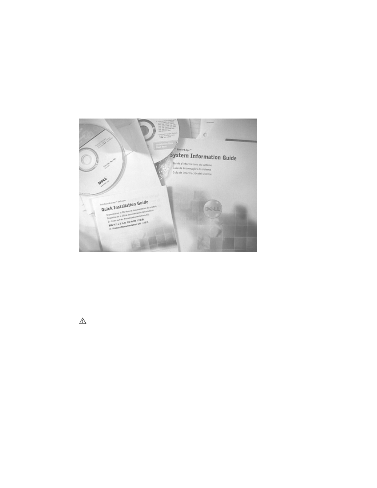
Dell Server Documentation
If your system includes a Grass Valley product on a Dell server platform, refer to the applicable
Grass Valley product manual for installation and configuration information. However, a full set of
Dell server documentation has been provided on the Dell Product Documentation CD-ROM. Refer
to the documents on this CD-ROM only as required by procedures in Grass Valley product manual.
Preface
Information referenced on the Dell Product Documentation CD-ROM includes, but is not limited
to:
• Unpacking and rack-mounting
• Important safety and regulatory information
• Status indicators, messages, and error codes
• Troubleshooting help
CAUTION: Do not use the Dell Quick Installation Guide provided with the Dell CD-ROM
package. This guide includes instructions for using the OpenManage software CD-ROM to
install an operating system, which is not necessary on the Grass Valley product.
02 February 2012 K2 Summit 3G Production Client Service Manual 13
Page 14

Page 15

Safety Summaries
Safety Summary
Read and follow the important safety information below, noting especially those instructions related
to risk of fire, electric shock or injury to persons. Additional specific warnings not listed here may
be found throughout the manual.
WARNING: Any instructions in this manual that require opening the equipment cover
or enclosure are for use by qualified service personnel only. To reduce the risk of electric
shock, do not perform any servicing other than that contained in the operating instructions
unless you are qualified to do so.
Safety terms and symbols
Terms in this manual
Safety-related statements may appear in this manual in the following form:
WARNING: Warning statements identify conditions or practices that may result in
personal injury or loss of life.
CAUTION: Caution statements identify conditions or practices that may result in damage
to equipment or other property, or which may cause equipment crucial to your business
environment to become temporarily non-operational.
Terms on the product
These terms may appear on the product:
DANGER — A personal injury hazard is immediately accessible as you read the marking.
WARNING — A personal injury hazard exists but is not immediately accessible as you read the
marking.
CAUTION — A hazard to property, product, and other equipment is present.
Symbols on the product
The following symbols may appear on the product:
Indicates that dangerous high voltage is present within the equipment enclosure that may
be of sufficient magnitude to constitute a risk of electric shock.
Indicates that user, operator or service technician should refer to product manual(s) for
important operating, maintenance, or service instructions.
This is a prompt to note fuse rating when replacing fuse(s). The fuse referenced in the text
must be replaced with one having the ratings indicated.
02 February 2012 K2 Summit 3G Production Client Service Manual 15
Page 16

Safety Summaries
Warnings
Identifies a protective grounding terminal which must be connected to earth ground prior
to making any other equipment connections.
Identifies an external protective grounding terminal which may be connected to earth
ground as a supplement to an internal grounding terminal.
Indicates that static sensitive components are present which may be damaged by electrostatic
discharge. Use anti-static procedures, equipment and surfaces during servicing.
The following warning statements identify conditions or practices that can result in personal injury
or loss of life.
Dangerous voltage or current may be present — Disconnect power and remove battery (if applicable)
before removing protective panels, soldering, or replacing components.
Do not service alone — Do not internally service this product unless another person capable of
rendering first aid and resuscitation is present.
Remove jewelry — Prior to servicing, remove jewelry such as rings, watches, and other metallic
objects.
Avoid exposed circuitry — Do not touch exposed connections, components or circuitry when power
is present.
Use proper power cord — Use only the power cord supplied or specified for this product.
Ground product — Connect the grounding conductor of the power cord to earth ground.
Operate only with covers and enclosure panels in place — Do not operate this product when covers
or enclosure panels are removed.
Use correct fuse — Use only the fuse type and rating specified for this product.
Use only in dry environment — Do not operate in wet or damp conditions.
Use only in non-explosive environment — Do not operate this product in an explosive atmosphere.
High leakage current may be present — Earth connection of product is essential before connecting
power.
Dual power supplies may be present — Be certain to plug each power supply cord into a separate
branch circuit employing a separate service ground. Disconnect both power supply cords prior to
servicing.
Double pole neutral fusing — Disconnect mains power prior to servicing.
Use proper lift points — Do not use door latches to lift or move equipment.
Avoid mechanical hazards — Allow all rotating devices to come to a stop before servicing.
Cautions
The following caution statements identify conditions or practices that can result in damage to
equipment or other property
Use correct power source — Do not operate this product from a power source that applies more than
the voltage specified for the product.
16 K2 Summit 3G Production Client Service Manual 02 February 2012
Page 17

Safety Summaries
Use correct voltage setting — If this product lacks auto-ranging power supplies, before applying
power ensure that the each power supply is set to match the power source.
Provide proper ventilation — To prevent product overheating, provide equipment ventilation in
accordance with installation instructions.
Use anti-static procedures — Static sensitive components are present which may be damaged by
electrostatic discharge. Use anti-static procedures, equipment and surfaces during servicing.
Do not operate with suspected equipment failure — If you suspect product damage or equipment
failure, have the equipment inspected by qualified service personnel.
Ensure mains disconnect — If mains switch is not provided, the power cord(s) of this equipment
provide the means of disconnection. The socket outlet must be installed near the equipment and
must be easily accessible. Verify that all mains power is disconnected before installing or removing
power supplies and/or options.
Route cable properly — Route power cords and other cables so that they ar not likely to be damaged.
Properly support heavy cable bundles to avoid connector damage.
Use correct power supply cords — Power cords for this equipment, if provided, meet all North
American electrical codes. Operation of this equipment at voltages exceeding 130 VAC requires
power supply cords which comply with NEMA configurations. International power cords, if provided,
have the approval of the country of use.
Use correct replacement battery — This product may contain batteries. To reduce the risk of explosion,
check polarity and replace only with the same or equivalent type recommended by manufacturer.
Dispose of used batteries according to the manufacturer’s instructions.
Troubleshoot only to board level — Circuit boards in this product are densely populated with surface
mount technology (SMT) components and application specific integrated circuits (ASICS). As a
result, circuit board repair at the component level is very difficult in the field, if not impossible. For
warranty compliance, do not troubleshoot systems beyond the board level.
Sicherheit – Überblick
Lesen und befolgen Sie die wichtigen Sicherheitsinformationen dieses Abschnitts. Beachten Sie
insbesondere die Anweisungen bezüglich
Brand-, Stromschlag- und Verletzungsgefahren. Weitere spezifische, hier nicht aufgeführte
Warnungen finden Sie im gesamten Handbuch.
WARNUNG: Alle Anweisungen in diesem Handbuch, die das Abnehmen der
Geräteabdeckung oder des Gerätegehäuses erfordern, dürfen nur von qualifiziertem
Servicepersonal ausgeführt werden. Um die Stromschlaggefahr zu verringern, führen
Sie keine Wartungsarbeiten außer den in den Bedienungsanleitungen genannten Arbeiten
aus, es sei denn, Sie besitzen die entsprechende Qualifikationen für diese Arbeiten.
Sicherheit – Begriffe und Symbole
In diesem Handbuch verwendete Begriffe
Sicherheitsrelevante Hinweise können in diesem Handbuch in der folgenden Form auftauchen:
02 February 2012 K2 Summit 3G Production Client Service Manual 17
Page 18

Safety Summaries
WARNUNG: Warnungen weisen auf Situationen oder Vorgehensweisen hin, die
Verletzungs- oder Lebensgefahr bergen.
VORSICHT: Vorsichtshinweise weisen auf Situationen oder Vorgehensweisen hin, die
zu Schäden an Ausrüstungskomponenten oder anderen Gegenständen oder zum zeitweisen
Ausfall wichtiger Komponenten in der Arbeitsumgebung führen können.
Hinweise am Produkt
Die folgenden Hinweise können sich am Produkt befinden:
GEFAHR – Wenn Sie diesen Begriff lesen, besteht ein unmittelbares Verletzungsrisiko.
WARNUNG – Wenn Sie diesen Begriff lesen, besteht ein mittelbares Verletzungsrisiko.
VORSICHT – Es besteht ein Risiko für Objekte in der Umgebung, den Mixer selbst oder andere
Ausrüstungskomponenten.
Symbole am Produkt
Die folgenden Symbole können sich am Produkt befinden:
Warnungen
Die folgenden Warnungen weisen auf Bedingungen oder Vorgehensweisen hin, die Verletzungsoder Lebensgefahr bergen:
Gefährliche Spannungen oder Ströme – Schalten Sie den Strom ab, und entfernen Sie ggf. die Batterie,
bevor sie Schutzabdeckungen abnehmen, löten oder Komponenten austauschen.
Weist auf eine gefährliche Hochspannung im Gerätegehäuse hin, die stark genug sein kann,
um eine Stromschlaggefahr darzustellen.
Weist darauf hin, dass der Benutzer, Bediener oder Servicetechniker wichtige Bedienungs-,
Wartungs- oder Serviceanweisungen in den Produkthandbüchern lesen sollte.
Dies ist eine Aufforderung, beim Wechsel von Sicherungen auf deren Nennwert zu achten.
Die im Text angegebene Sicherung muss durch eine Sicherung ersetzt werden, die die
angegebenen Nennwerte besitzt.
Weist auf eine Schutzerdungsklemme hin, die mit dem Erdungskontakt verbunden werden
muss, bevor weitere Ausrüstungskomponenten angeschlossen werden.
Weist auf eine externe Schutzerdungsklemme hin, die als Ergänzung zu einem internen
Erdungskontakt an die Erde angeschlossen werden kann.
Weist darauf hin, dass es statisch empfindliche Komponenten gibt, die durch eine
elektrostatische Entladung beschädigt werden können. Verwenden Sie antistatische
Prozeduren, Ausrüstung und Oberflächen während der Wartung.
Servicearbeiten nicht alleine ausführen – Führen Sie interne Servicearbeiten nur aus, wenn eine
weitere Person anwesend ist, die erste Hilfe leisten und Wiederbelebungsmaßnahmen einleiten kann.
Schmuck abnehmen – Legen Sie vor Servicearbeiten Schmuck wie Ringe, Uhren und andere
metallische Objekte ab.
18 K2 Summit 3G Production Client Service Manual 02 February 2012
Page 19

Safety Summaries
Keine offen liegenden Leiter berühren – Berühren Sie bei eingeschalteter Stromzufuhr keine offen
liegenden Leitungen, Komponenten oder Schaltungen.
Richtiges Netzkabel verwenden – Verwenden Sie nur das mitgelieferte Netzkabel oder ein Netzkabel,
das den Spezifikationen für dieses Produkt entspricht.
Gerät erden – Schließen Sie den Erdleiter des Netzkabels an den Erdungskontakt an.
Gerät nur mit angebrachten Abdeckungen und Gehäuseseiten betreiben – Schalten Sie dieses Gerät
nicht ein, wenn die Abdeckungen oder Gehäuseseiten entfernt wurden.
Richtige Sicherung verwenden – Verwenden Sie nur Sicherungen, deren Typ und Nennwert den
Spezifikationen für dieses Produkt entsprechen.
Gerät nur in trockener Umgebung verwenden – Betreiben Sie das Gerät nicht in nassen oder feuchten
Umgebungen.
Gerät nur verwenden, wenn keine Explosionsgefahr besteht – Verwenden Sie dieses Produkt nur in
Umgebungen, in denen keinerlei Explosionsgefahr besteht.
Hohe Kriechströme – Das Gerät muss vor dem Einschalten unbedingt geerdet werden.
Doppelte Spannungsversorgung kann vorhanden sein – Schließen Sie die beiden Anschlußkabel an
getrennte Stromkreise an. Vor Servicearbeiten sind beide Anschlußkabel vom Netz zu trennen.
Vorsicht
Zweipolige, neutrale Sicherung – Schalten Sie den Netzstrom ab, bevor Sie mit den Servicearbeiten
beginnen.
Fassen Sie das Gerät beim Transport richtig an – Halten Sie das Gerät beim Transport nicht an Türen
oder anderen beweglichen Teilen fest.
Gefahr durch mechanische Teile – Warten Sie, bis der Lüfter vollständig zum Halt gekommen ist,
bevor Sie mit den Servicearbeiten beginnen.
Die folgenden Vorsichtshinweise weisen auf Bedingungen oder Vorgehensweisen hin, die zu Schäden
an Ausrüstungskomponenten oder anderen Gegenständen führen können:
Gerät nicht öffnen – Durch das unbefugte Öffnen wird die Garantie ungültig.
Richtige Spannungsquelle verwenden – Betreiben Sie das Gerät nicht an einer Spannungsquelle, die
eine höhere Spannung liefert als in den Spezifikationen für dieses Produkt angegeben.
Gerät ausreichend belüften – Um eine Überhitzung des Geräts zu vermeiden, müssen die
Ausrüstungskomponenten entsprechend den Installationsanweisungen belüftet werden. Legen Sie
kein Papier unter das Gerät. Es könnte die Belüftung behindern. Platzieren Sie das Gerät auf einer
ebenen Oberfläche.
Antistatische Vorkehrungen treffen – Es gibt statisch empfindliche Komponenten, die durch eine
elektrostatische Entladung beschädigt werden können. Verwenden Sie antistatische Prozeduren,
Ausrüstung und Oberflächen während der Wartung.
CF-Karte nicht mit einem PC verwenden – Die CF-Karte ist speziell formatiert. Die auf der CF-Karte
gespeicherte Software könnte gelöscht werden.
Gerät nicht bei eventuellem Ausrüstungsfehler betreiben – Wenn Sie einen Produktschaden oder
Ausrüstungsfehler vermuten, lassen Sie die Komponente von einem qualifizierten Servicetechniker
untersuchen.
02 February 2012 K2 Summit 3G Production Client Service Manual 19
Page 20

Safety Summaries
Consignes desécurité
Kabel richtig verlegen – Verlegen Sie Netzkabel und andere Kabel so, dass Sie nicht beschädigt
werden. Stützen Sie schwere Kabelbündel ordnungsgemäß ab, damit die Anschlüsse nicht beschädigt
werden.
Richtige Netzkabel verwenden – Wenn Netzkabel mitgeliefert wurden, erfüllen diese alle nationalen
elektrischen Normen. Der Betrieb dieses Geräts mit Spannungen über 130 V AC erfordert Netzkabel,
die NEMA-Konfigurationen entsprechen. Wenn internationale Netzkabel mitgeliefert wurden, sind
diese für das Verwendungsland zugelassen.
Richtige Ersatzbatterie verwenden – Dieses Gerät enthält eine Batterie. Um die Explosionsgefahr zu
verringern, prüfen Sie die Polarität und tauschen die Batterie nur gegen eine Batterie desselben Typs
oder eines gleichwertigen, vom Hersteller empfohlenen Typs aus. Entsorgen Sie gebrauchte Batterien
entsprechend den Anweisungen des Batterieherstellers.
Das Gerät enthält keine Teile, die vom Benutzer gewartet werden können. Wenden Sie sich bei
Problemen bitte an den nächsten Händler.
Il est recommandé de lire, de bien comprendre et surtout de respecter les informations relatives à
la sécurité qui sont exposées ci-après, notamment les consignes destinées à prévenir les risques
d’incendie, les décharges électriques et les blessures aux personnes. Les avertissements
complémentaires, qui ne sont pas nécessairement repris ci-dessous, mais présents dans toutes les
sections du manuel, sont également à prendre en considération.
AVERTISSEMENT: Toutes les instructions présentes dans ce manuel qui concernent
l’ouverture des capots ou des logements de cet équipement sont destinées exclusivement
à des membres qualifiés du personnel de maintenance. Afin de diminuer les risques de
décharges électriques, ne procédez à aucune intervention d’entretien autre que celles
contenues dans le manuel de l’utilisateur, à moins que vous ne soyez habilité pour le
faire.
Consignes et symboles de sécurité
Termes utilisés dans ce manuel
Les consignes de sécurité présentées dans ce manuel peuvent apparaître sous les formes suivantes
:
AVERTISSEMENT: Les avertissements signalent des conditions ou des pratiques
susceptibles d’occasionner des blessures graves, voire même fatales.
MISE EN GARDE: Les mises en garde signalent des conditions ou des pratiques
susceptibles d’occasionner un endommagement à l’équipement ou aux installations, ou
de rendre l’équipement temporairement non opérationnel, ce qui peut porter préjudice
à vos activités.
Signalétique apposée sur le produit
La signalétique suivante peut être apposée sur le produit :
DANGER — risque de danger imminent pour l’utilisateur.
20 K2 Summit 3G Production Client Service Manual 02 February 2012
Page 21

Safety Summaries
AVERTISSEMENT — Risque de danger non imminent pour l’utilisateur.
MISE EN GARDE — Risque d’endommagement du produit, des installations ou des autres équipements.
Symboles apposés sur le produit
Les symboles suivants peut être apposés sur le produit :
Signale la présence d’une tension élevée et dangereuse dans le boîtier de l’équipement ;
cette tension peut être suffisante pour constituer un risque de décharge électrique.
Signale que l’utilisateur, l’opérateur ou le technicien de maintenance doit faire référence
au(x) manuel(s) pour prendre connaissance des instructions d’utilisation, de maintenance
ou d’entretien.
Il s’agit d’une invite à prendre note du calibre du fusible lors du remplacement de ce dernier.
Le fusible auquel il est fait référence dans le texte doit être remplacé par un fusible du
même calibre.
Identifie une borne de protection de mise à la masse qui doit être raccordée correctement
avant de procéder au raccordement des autres équipements.
I dentifie une borne de protection de mise à la masse qui peut être connectée en tant que
borne de mise à la masse supplémentaire.
Avertissements
Les avertissements suivants signalent des conditions ou des pratiques susceptibles d’occasionner
des blessures graves, voire même fatales :
Présence possible de tensions ou de courants dangereux — Mettez hors tension, débranchez et
retirez la pile (le cas échéant) avant de déposer les couvercles de protection, de défaire une soudure
ou de remplacer des composants.
Ne procédez pas seul à une intervention d’entretien — Ne réalisez pas une intervention d’entretien
interne sur ce produit si une personne n’est pas présente pour fournir les premiers soins en cas
d’accident.
Retirez tous vos bijoux — Avant de procéder à une intervention d’entretien, retirez tous vos bijoux,
notamment les bagues, la montre ou tout autre objet métallique.
Évitez tout contact avec les circuits exposés — Évitez tout contact avec les connexions, les composants
ou les circuits exposés s’ils sont sous tension.
Utilisez le cordon d’alimentation approprié — Utilisez exclusivement le cordon d’alimentation fourni
avec ce produit ou spécifié pour ce produit.
Signale la présence de composants sensibles à l’électricité statique et qui sont susceptibles
d’être endommagés par une décharge électrostatique. Utilisez des procédures, des
équipements et des surfaces antistatiques durant les interventions d’entretien.
Raccordez le produit à la masse — Raccordez le conducteur de masse du cordon d’alimentation à
la borne de masse de la prise secteur.
Utilisez le produit lorsque les couvercles et les capots sont en place — N’utilisez pas ce produit si
les couvercles et les capots sont déposés.
02 February 2012 K2 Summit 3G Production Client Service Manual 21
Page 22

Safety Summaries
Utilisez le bon fusible — Utilisez exclusivement un fusible du type et du calibre spécifiés pour ce
produit.
Utilisez ce produit exclusivement dans un environnement sec — N’utilisez pas ce produit dans un
environnement humide.
Utilisez ce produit exclusivement dans un environnement non explosible — N’utilisez pas ce produit
dans un environnement dont l’atmosphère est explosible.
Présence possible de courants de fuite — Un raccordement à la masse est indispensable avant la
mise sous tension.
Deux alimentations peuvent être présentes dans l’équipement — Assurez vous que chaque cordon
d’alimentation est raccordé à des circuits de terre séparés. Débranchez les deux cordons d’alimentation
avant toute intervention.
Fusion neutre bipolaire — Débranchez l’alimentation principale avant de procéder à une intervention
d’entretien.
Utilisez les points de levage appropriés — Ne pas utiliser les verrous de la porte pour lever ou déplacer
l’équipement.
Évitez les dangers mécaniques — Laissez le ventilateur s’arrêter avant de procéder à une intervention
d’entretien.
Mises en garde
Les mises en garde suivantes signalent les conditions et les pratiques susceptibles d’occasionner
des endommagements à l’équipement et aux installations :
N’ouvrez pas l’appareil — Toute ouverture prohibée de l’appareil aura pour effet d’annuler la garantie.
Utilisez la source d’alimentation adéquate — Ne branchez pas ce produit à une source d’alimentation
qui utilise une tension supérieure à la tension nominale spécifiée pour ce produit.
Assurez une ventilation adéquate — Pour éviter toute surchauffe du produit, assurez une ventilation
de l’équipement conformément aux instructions d’installation. Ne déposez aucun document sous
l’appareil – ils peuvent gêner la ventilation. Placez l’appareil sur une surface plane.
Utilisez des procédures antistatiques - Les composants sensibles à l’électricité statique présents dans
l’équipement sont susceptibles d’être endommagés par une décharge électrostatique. Utilisez des
procédures, des équipements et des surfaces antistatiques durant les interventions d’entretien.
N’utilisez pas la carte CF avec un PC — La carte CF a été spécialement formatée. Le logiciel enregistré
sur la carte CF risque d’être effacé.
N’utilisez pas l’équipement si un dysfonctionnement est suspecté — Si vous suspectez un
dysfonctionnement du produit, faites inspecter celui-ci par un membre qualifié du personnel
d’entretien.
Acheminez les câbles correctement — Acheminez les câbles d’alimentation et les autres câbles de
manière à ce qu’ils ne risquent pas d’être endommagés. Supportez correctement les enroulements
de câbles afin de ne pas endommager les connecteurs.
Utilisez les cordons d’alimentation adéquats — Les cordons d’alimentation de cet équipement, s’ils
sont fournis, satisfont aux exigences de toutes les réglementations régionales. L’utilisation de cet
équipement à des tensions dépassant les 130 V en c.a. requiert des cordons d’alimentation qui
satisfont aux exigences des configurations NEMA. Les cordons internationaux, s’ils sont fournis,
ont reçu l’approbation du pays dans lequel l’équipement est utilisé.
22 K2 Summit 3G Production Client Service Manual 02 February 2012
Page 23

Utilisez une pile de remplacement adéquate — Ce produit renferme une pile. Pour réduire le risque
d’explosion, vérifiez la polarité et ne remplacez la pile que par une pile du même type, recommandée
par le fabricant. Mettez les piles usagées au rebut conformément aux instructions du fabricant des
piles.
Cette unité ne contient aucune partie qui peut faire l’objet d’un entretien par l’utilisateur. Si un
problème survient, veuillez contacter votre distributeur local.
Certifications and compliances
Canadian certified power cords
Canadian approval includes the products and power cords appropriate for use in the North America
power network. All other power cords supplied are approved for the country of use.
FCC emission control
This equipment has been tested and found to comply with the limits for a Class A digital device,
pursuant to Part 15 of the FCC Rules. These limits are designed to provide reasonable protection
against harmful interference when the equipment is operated in a commercial environment. This
equipment generates, uses, and can radiate radio frequency energy and, if not installed and used in
accordance with the instruction manual, may cause harmful interference to radio communications.
Operation of this equipment in a residential area is likely to cause harmful interference in which
case the user will be required to correct the interference at his own expense. Changes or modifications
not expressly approved by Grass Valley can affect emission compliance and could void the user’s
authority to operate this equipment.
Safety Summaries
Canadian EMC Notice of Compliance
This digital apparatus does not exceed the Class A limits for radio noise emissions from digital
apparatus set out in the Radio Interference Regulations of the Canadian Department of
Communications.
Le présent appareil numérique n’émet pas de bruits radioélectriques dépassant les limites applicables
aux appareils numériques de la classe A préscrites dans le Règlement sur le brouillage radioélectrique
édicté par le ministère des Communications du Canada.
EN55103 1/2 Class A warning
This product has been evaluated for Electromagnetic Compatibility under the EN 55103-1/2 standards
for Emissions and Immunity and meets the requirements for E4 environment.
This product complies with Class A (E4 environment). In a domestic environment this product may
cause radio interference in which case the user may be required to take adequate measures.
FCC emission limits
This device complies with Part 15 of the FCC Rules. Operation is subject to the following two
conditions: (1) This device may not cause harmful interference, and (2) this device must accept any
interference received, including interference that may cause undesirable operation.
02 February 2012 K2 Summit 3G Production Client Service Manual 23
Page 24

Safety Summaries
Laser compliance
Laser safety requirements
This product may contain a Class 1 certified laser device. Operating this product outside specifications
or altering its original design may result in hazardous radiation exposure, and may be considered
an act of modifying or new manufacturing of a laser product under U.S. regulations contained in
21CFR Chapter 1, subchapter J or CENELEC regulations in HD 482 S1. People performing such
an act are required by law to recertify and reidentify this product in accordance with provisions of
21CFR subchapter J for distribution within the U.S.A., and in accordance with CENELEC HD 482
S1 for distribution within countries using the IEC 825 standard.
Laser safety
Laser safety in the United States is regulated by the Center for Devices and Radiological Health
(CDRH). The laser safety regulations are published in the “Laser Product Performance Standard,”
Code of Federal Regulation (CFR), Title 21, Subchapter J.
The International Electrotechnical Commission (IEC) Standard 825, “Radiation of Laser Products,
Equipment Classification, Requirements and User’s Guide,” governs laser products outside the
United States. Europe and member nations of the European Free Trade Association fall under the
jurisdiction of the Comité Européen de Normalization Electrotechnique (CENELEC).
Safety certification
This product has been evaluated and meets the following Safety Certification Standards:
ANSI/UL 60950-1
IEC 60950-1 with CB cert.
CAN/CSA C22.2 No. 60950-1
BS EN 60950-1
ESD Protection
Electronics today are more susceptible to electrostatic discharge (ESD) damage than older equipment.
Damage to equipment can occur by ESD fields that are smaller than you can feel. Implementing the
information in this section will help you protect the investment that you have made in purchasing
Grass Valley equipment. This section contains Grass Valley’s recommended ESD guidelines that
should be followed when handling electrostatic discharge sensitive (ESDS) items. These minimal
recommendations are based on the information in the Sources of ESD and Risks on page 25 area.
The information in Grounding Requirements for Personnel on page 26 is provided to assist you in
selecting an appropriate grounding method.
Designed/tested for compliance with:Standard
Safety of Information Technology Equipment, including
Electrical Business Equipment (Second edition 2007).
Safety of Information Technology Equipment, including
Electrical Business Equipment (Second edition, 2005).
Safety of Information Technology Equipment, including
Electrical Business Equipment (Second edition 2007).
Safety of Information Technology Equipment, including
Electrical Business Equipment 2006.
24 K2 Summit 3G Production Client Service Manual 02 February 2012
Page 25

Recommended ESD Guidelines
Follow these guidelines when handling Grass Valley equipment:
• Only trained personnel that are connected to a grounding system should handle ESDS items.
• Do not open any protective bag, box, or special shipping packaging until you have been grounded.
NOTE: When a Personal Grounding strap is unavailable, as an absolute minimum, touch a
metal object that is touching the floor (for example, a table, frame, or rack) to discharge any
static energy before touching an ESDS item.
• Open the anti-static packaging by slitting any existing adhesive tapes. Do not tear the tapes off.
• Remove the ESDS item by holding it by its edges or by a metal panel.
• Do not touch the components of an ESDS item unless it is absolutely necessary to configure or
repair the item.
• Keep the ESDS work area clear of all nonessential items such as coffee cups, pens, wrappers
and personal items as these items can discharge static. If you need to set an ESDS item down,
place it on an anti-static mat or on the anti-static packaging.
Sources of ESD and Risks
Safety Summaries
The following information identifies possible sources of electrostatic discharge and can be used to
help establish an ESD policy.
Personnel
One of the largest sources of static is personnel. The static can be released from a person’s clothing
and shoes.
Environment
The environment includes the humidity and floors in a work area. The humidity level must be
controlled and should not be allowed to fluctuate over a broad range. Relative humidity (RH) is a
major part in determining the level of static that is being generated. For example, at 10% - 20% RH
a person walking across a carpeted floor can develop 35kV; yet when the relative humidity is
increased to 70% - 80%, the person can only generate 1.5kV.
Static is generated as personnel move (or as equipment is moved) across a floor’s surface. Carpeted
and waxed vinyl floors contribute to static build up.
Work Surfaces
Painted or vinyl-covered tables, chairs, conveyor belts, racks, carts, anodized surfaces, plexiglass
covers, and shelving are all static generators.
Equipment
Any equipment commonly found in an ESD work area, such as solder guns, heat guns, blowers,
etc., should be grounded.
Materials
Plastic work holders, foam, plastic tote boxes, pens, packaging containers and other items commonly
found at workstations can generate static electricity.
02 February 2012 K2 Summit 3G Production Client Service Manual 25
Page 26

Safety Summaries
Grounding Requirements for Personnel
The information in this section is provided to assist you in selecting a grounding method. This
information is taken from ANSI/ESD S20.20-2007 (Revision of ANSI/ESD S20.20-1999).
Product Qualification
Required LimitsTest MethodPersonnel Grounding Technical
Requirement
< 3.5 x 10⁷ ohmANSI/ESD S1.1 (Section 5.11)Wrist Strap System*
< 3.5 x 10⁷ ohmANSI/ESD STM97.1Flooring / Footwear System –
Method 1
Flooring / Footwear System –
Method 2 (both required)
1ANSI/ESD STM97.2
< 109 ohmANSI/ESD STM97.
< 100 VANSI/ESD STM97.2
Product qualification is normally conducted during the initial selection of ESD control products and
materials. Any of the following methods can be used: product specification review, independent
laboratory evaluation, or internal laboratory evaluation.
Compliance Verification
Required LimitsTest MethodPersonnel Grounding Technical
Requirement
< 3.5 x 10⁷ ohmESD TR53 Wrist Strap SectionWrist Strap System*
Flooring / Footwear System –
Method 1
Flooring / Footwear System –
Method 2 (both required)
ESD TR53 Footwear Section
ESD TR53 Footwear Section
< 3.5 x 10⁷ ohmESD TR53 Flooring Section and
< 1.0 x 10⁹ ohmESD TR53 Flooring Section and
* For situations where an ESD garment is used as part of the wrist strap grounding path, the total
system resistance, including the person, garment, and grounding cord, must be less than 3.5 x 10
ohm.
7
26 K2 Summit 3G Production Client Service Manual 02 February 2012
Page 27

Chapter 1
Product description
This section contains the following topics:
• Overview description
• K2 Summit 3G system orientation
• FRU functional descriptions
• System Overview
• Status indicators
02 February 2012 K2 Summit 3G Production Client Service Manual 27
Page 28

Product description
Overview description
The K2 Summit system is a cost-effective media platform that incorporates IT and storage
technologies. It delivers a networked solution to facilities for replay in sports, news, live, and
live-to-tape applications, as well as ingest, playout, and media asset management. It is a
comprehensive platform that provides a suite of user applications, system tools, and the largest range
of third party interactivity in the industry.
Refer to the "K2 System Guide" for other high-level descriptions of features, controls, applications,
and subsystems.
K2 Summit 3G system features
The following features apply to the K2 Summit 3G Production Client:
• Bidirectional channels (channel can be either an input channel or it can be an output channel)
• Two or four channels per chassis
• SDI video inputs and outputs
• AES/EBU or embedded audio inputs and outputs.
• Standard Definition (SD) video formats and High Definition (HD) video formats
• AVCHD play output (decode) support as an option.
• 3G codec module hosts codec option cards that are programmable for multiple formats and
• Mixed format playback of SD or HD clips on the same timeline
• Up/down/cross HD/SD conversion (e.g. SD and HD clips ingested, then played back as SD or
• VGA monitoring capability
• Redundant power supply, cooling fans for reliability
• 2.5 inch media storage drives
• mSATA SSD system drive protected by a file-based write filter
• USB 3.0 interface for file exchange
• Ability to create nested bins, i.e. sub-bins within bins
• Freeze mode can be frame or field
• Various video mix effects (e.g. dissolves between two video and audio tracks on the same channel,
• Remote operation and configuration via AppCenter
• NetCentral™ provides remote error reporting and monitoring via SNMP (Optional for models
• Gigabit Ethernet
• AMP, VDCP, and BVW remote control protocols supported
• Remote control over RS-422 or Ethernet
• Super Slo-Mo, Multi-cam, and 3D/Video + Key features are available as part of the ChannelFlex
• Multi-Cam XDCAMHD and Super Slo-Mo AVC-Intra
• Low-resolution proxy files created during record and live streaming from SDI In/out are available
functions.
HD clips) or as a different SD or HD format (e.g. 720p to 1080i).
or fade thru matte color)
using local storage only)
Suite
as part of the AppCenter Pro and Elite licenses
28 K2 Summit 3G Production Client Service Manual 02 February 2012
Page 29
• RAID media storage
USB compartment
(Clip behind bezel)
Note: removing the bezel takes
the fans offline. Replace the bezel assembly
within one minute to maintain system cooling.
Serial Number
This is also the factory
default hostname
• Stand-alone internal storage, stand-alone external direct-connect storage, and external shared
(SAN) storage
Product identification K2 Summit 3G
The K2 Summit 3G system has labels affixed to the chassis that provide product identification as
illustrated:
Product description
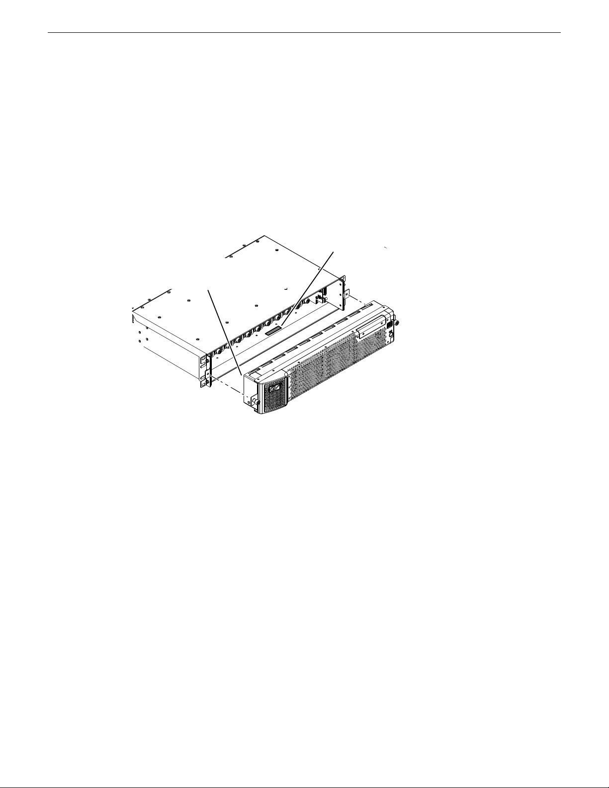
K2 Summit 3G system orientation
The following illustration shows the location of Field Replaceable Units (FRUs) and other components
in the K2 Summit 3G system.
02 February 2012 K2 Summit 3G Production Client Service Manual 29
Page 30
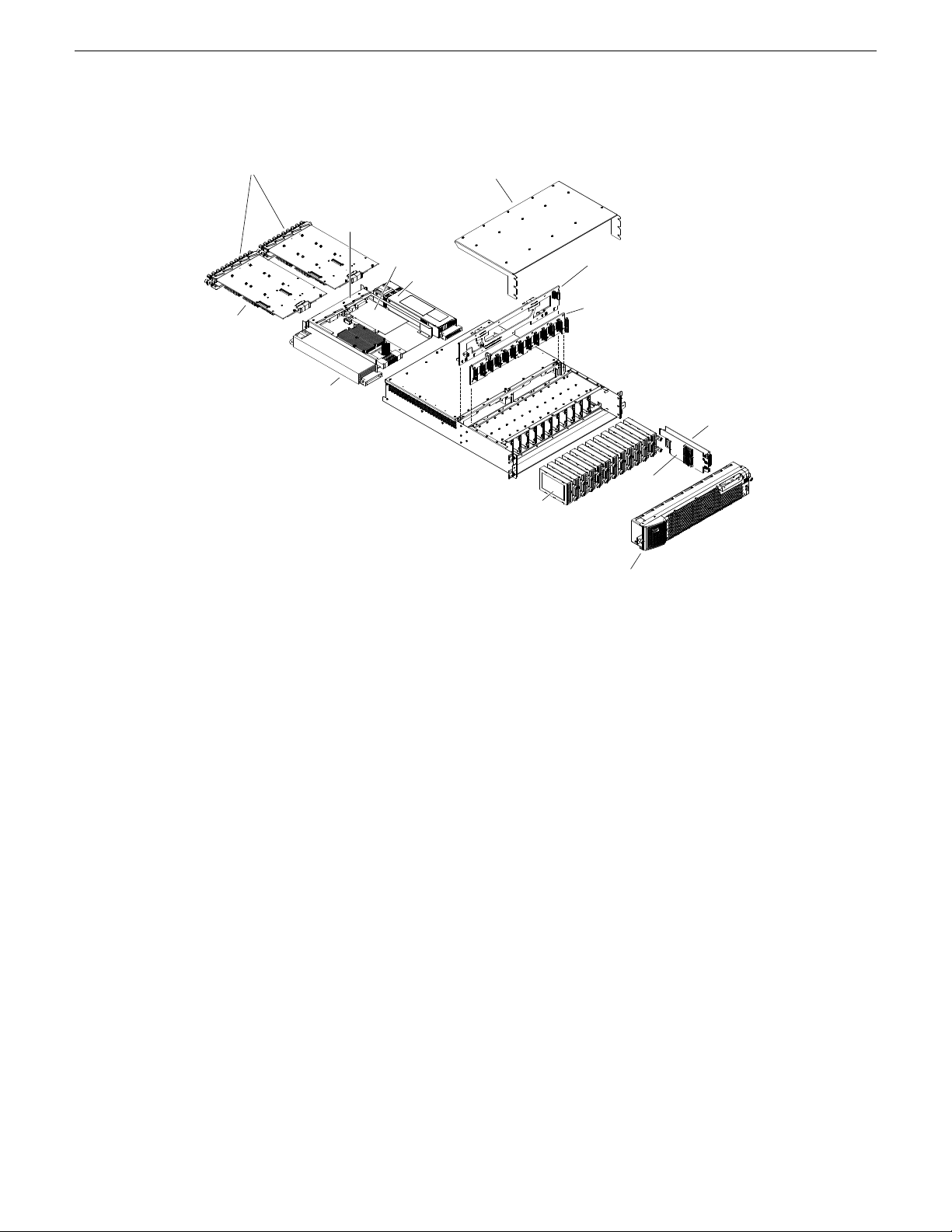
Codec modules
Top cover
Disk
controller
board
Front
interconnect
board
(with mSATA
boot media)
Disk modules
Front bezel assembly
Codec option card
(attached to underside
of each codec module)
Power supply
module
Power supply module
Carrier module
Optional PCIe board
Disk backplane
Midplane
Product description
FRU functional descriptions
K2 Summit system Field Replaceable Units (FRUs) are described in this section.
Front bezel assembly
The front bezel assembly includes the bezel, fans, and fan status board. The assembly has four fans
and provides cooling for the K2 Summit system chassis. Air intake is from the front of the K2
Summit system and outflow is through the rear. The assembly connects to the front interconnect
board and is secured to the chassis by two thumbscrews.
Disk modules
There are slots for disk modules in the K2 Summit system. The slots are located behind the front
bezel assembly in the front of the chassis. Each slot can contain one disk module, and each module
contains one hard drive. Depending on storage options, a K2 Summit system can be fully populated,
partially populated, or can contain no disk modules. Disk modules plug into the disk backplane
board.
Data is written or “striped” across the disks in a continuous fashion, which makes the disks a “stripe
group”. This stripe group appears as the V: drive to the Windows operating system.
30 K2 Summit 3G Production Client Service Manual 02 February 2012
Page 31

The V: drive stores media. It also stores media file system, database, and configuration information.
K2 Summit systems with direct-connect storage or shared SAN storage do not contain disk modules,
as the V: drive is on the external RAID storage devices.
When configured as RAID 1, you can remove and replace a disk module while the K2 Summit
system is operational.
Related Topics
Disk module removal on page 99
mSATA boot media
The mSATA SSD boot media contains the system drive, also known as the C: drive. The C: drive
contains application and operating system files. The mSATA media is hosted by the front interconnect
board.
Related Topics
mSATA boot media removal on page 101
Product description
Power supply modules
The K2 Summit system has redundant (two) power supplies. You should connect a power cable to
each power supply, but both power supplies remain operational if only one cable is connected. The
power supplies can be accessed from the rear of the unit. You can remove and replace a power
supply while the K2 Summit system is operational. Each power supply has a fan with automatic
speed control and status LEDs that indicate current state and health. The power supply has protection
for over voltage, over current, and short circuits. The power supply modules plug into the midplane
board.
Related Topics
Power supply problems on page 87
Power supply module removal on page 102
Codec module
The K2 Summit system has slots for two codec modules. Each codec module hosts two media
input/output channels. The codec modules are oriented horizontally across the rear of the K2 Summit
system chassis. They provide the majority of the K2 Summit system’s media-related input and
output connectors on the rear panel. The codec modules plug into the midplane board.
A codec module can host a codec option card. The codec option card provides extended functionality
to the channels hosted by the codec module.
Related Topics
Codec module removal on page 102
02 February 2012 K2 Summit 3G Production Client Service Manual 31
Page 32

Product description
Codec option card
There is one type of codec option card available for the K2 Summit 3G system. The codec module
hosts the codec option card. The single codec option card provides functionality for both of the
codec module's channels.
Related Topics
Codec option card removal on page 103
Disk controller board
The disk controller board provides the RAID functionality for the internal disks. It is mounted in
the front of the unit. The disk controller board plugs into the disk backplane board and the midplane
board. K2 Summit systems with direct-connect storage or shared SAN storage do not contain a disk
controller board, as RAID disks are in the external RAID storage devices.
Related Topics
Disk controller board removal on page 100
Front interconnect board
The front interconnect board has the control and speed monitoring circuit for the fans and incorporates
a PCIE to dual USB 3.0 controller circuit. It hosts the boot media, standby switch, Power LED and
Service LED. The LEDs are driven by circuitry on the carrier module. The front interconnect board
is mounted in the front of the unit and plugs into the midplane board.
Disk backplane unit
The disk backplane unit includes the disk backplane board. The disk backplane board provides the
connections for the disk modules and hosts the disk status LEDs. It is mounted in the front center
of the chassis. It plugs into the disk controller board. A power cable connects the midplane board
and the disk backplane board. K2 Summit system with direct-connect storage or shared SAN storage
do not contain a disk backplane board, as RAID disks are in the external RAID storage devices.
Midplane board
The midplane board provides connections for the rear modules. The disk controller board and the
front interconnect board also plug into the midplane board. It is mounted in the center of the unit.
A power cable connects the midplane board and the disk backplane board, if present.
Related Topics
Midplane board removal on page 108
Carrier module
The carrier module provides the functionality typically associated with a motherboard in a PC. It
hosts the CPU, one optional PCIe board, and provides rear panel connections for Gigabit Ethernet,
32 K2 Summit 3G Production Client Service Manual 02 February 2012
Page 33

USB, VGA, and IEEE 1394a (Firewire). The IEEE 1394a port is for debugging purposes only. It
is not supported for customer use. Do not attempt to configure or otherwise use this port. The carrier
module also provides a GPI connection and connections for reference. It plugs into the midplane
board.
Related Topics
Carrier module removal on page 104
Fibre Channel board (optional)
The optional PCIe Fibre Channel board is hosted by the carrier module.
Related Topics
Fibre Channel board (optional) removal on page 105
System Overview
The K2 Summit system is a PCIe bus-based Windows computer with extensive enhancements to
provide the video disk recorder functionality. This section explains the major architectural blocks.
Product description
02 February 2012 K2 Summit 3G Production Client Service Manual 33
Page 34

CPU module
Codec
Board
Codec
Board
Midplane
Power Supply Power Supply
VGA Monitor
USB Mouse
USB Keyboard
Dual GigE Ports
Inputs and
Outputs:
Audio,
Video,
Timecode,
RS-422
*Not in external storage models
Dual GigE Ports
USB
Port(s)
Standby
switch
GPIO
Reference
Application
System
System
Resources
Real
Time
System
Optional Fibre
Channel Board
Fibre Channel Ports
Disk
Controller
Front
Connect
Fan
Status
Disk
Backplane
*
*
*Disk Modules
Fan
Boot
media
Codec
option
card(s)
Codec
option
card(s)
SATA
USB
SM
BUS
PCIe Switch
Product description
Status indicators
The following sections describe the visual and audible indicators that communicate the current
operating status and system health of the K2 Summit system.
Front panel indicators
The front bezel assembly must be installed for front panel LEDs to provide status.
34 K2 Summit 3G Production Client Service Manual 02 February 2012
Page 35

Power
LED
Standby
switch
Service
LED
Power LED
The Power LED indicates status as follows::
Product description
Status ConditionLED behavior
Off
Green steady on
Service LED
The following table explains the status conditions indicated by the different Service LED behaviors.
If two or more status conditions occur simultaneously, the LED displays the behavior for the highest
priority condition.
Flashing pattern alternating
Yellow/Green/Red/Off twice a
second
Solid Red
Solid Yellow
The standby switch is set to Off and the K2 Summit 3G system is not
operational.
The standby switch is set to On and the K2 Summit 3G system is either in
the startup process or has completed the startup process and is operational.
WARNING: The power standby switch does not turn off power to the system. To turn power off both
power supplies must be disconnected from the power source.
PriorityStatus ConditionLED behavior
1Identify — The K2 Summit system is being directed
to identify itself by NetCentral or some other
application.
2Global failure — The K2 Summit system software
has detected a critical error or failure that impacts
record/play operations.
3Warning — The K2 Summit system software has
detected a problem that requires attention but does
not immediately impact record/play operations. For
example, a fan or power supply has failed but its
redundant partner is maintaining functionality.
Flashing Yellow pattern three times
a second.
If RAID 1, the failure does not immediately impact
4Drive failure — An internal RAID drive has failed.
record/play operations. The redundant partner RAID
drive is maintaining functionality.
Flashing pattern alternating
Yellow/Green once a second.
02 February 2012 K2 Summit 3G Production Client Service Manual 35
is rebuilding.
5Drive rebuild — If RAID 1, an internal RAID drive
Page 36

RTP RTP
Green/Yellow/Orange
Green
Product description
PriorityStatus ConditionLED behavior
Off
Rear panel indicators
The following indicators are visible from the rear panel view.
Codec board indicator
Each channel has a green/red LED that indicates the status of the Real Time Processor (RTP).
Codec board indicator codes
Interpret the RTP LED as follows:
5Normal — The K2 Summit system is healthy and
operating normally.
approximately 1 second
intervals
1 second intervals
LAN connector indicator codes
The motherboard has four RJ-45 LAN connectors that include integrated status LEDs. The LEDs
are oriented as follows:
The meanings of the LED states are described in the following table:
Status conditionLED behavior
RTP is up and connected to the hostGreen flashing at
RTP is not connected to the host.Green flashing at greater than
RTP error condition. Real Time OS is not running.Red
Real Time OS is not running.Off
36 K2 Summit 3G Production Client Service Manual 02 February 2012
Page 37

If a LAN connector is faulty, you must replace the carrier module.
OK ~AC Fault
Power supply indicators
Each power supply has LEDs that indicates status.
Product description
Status ConditionLED stateLED
The adapter is connected to a valid link partnerGreen OnGreen
Data activityGreen flashing
No linkOff
10 MbpsOffGreen/Yellow/Orange
100 MbpsGreen
10000 MbpsYellow
IdentifyOrange flashing
Interpret the power supply LEDs as follows:
Status ConditionLED stateLED
The power supply is operating normally.Green OnOK
There is a power supply fault.Yellow OnFault
Green On~AC
The electrical current available to the power
supply meets power supply requirements. Input
> 85 VAC.
Another indicator of power supply operation is the audible fan noise. If a power cable is connected
to either power supply, the fan should stay on continuously on both power supplies. This is the case
even if the K2 Summit system is shut down or restarting via the standby switch or the Windows
operating system.
The Service LED on the front of the K2 Summit system also indicates power supply status.
If the power source and the power cord are OK yet there is still a power supply problem, the status
lights on the power supply indicate the problem.
Related Topics
Service LED on page 35
Power supply problems on page 87
02 February 2012 K2 Summit 3G Production Client Service Manual 37
Page 38

Reference
Product description
Reference indicator
There is a small hole in the carrier module next to the “REF. LOOP THROUGH” BNC connectors.
Through this hole a LED is visible. When the LED is lit, the reference signal is present and locked.
Internal indicators
You must remove one or more modules to expose the following indicators for viewing.
Disk module indicators
You must remove the front bezel assembly to see these LEDs. Each disk module has LEDs that
indicate status. The LEDs are located on the disk backplane. Flexible light pipes transmit the light
so that it appears on the disk pillar next to the disk module. The following table explains the status
conditions indicated by the different LED behaviors. If two or more status conditions occur
simultaneously, the LED displays the behavior for the highest priority condition. Priority number
1 is the highest priority
PriorityStatus ConditionLED behavior
Amber flashing pattern.
1Identify — The drive is being directed to identify
itself by Storage Utility or some other application.
Green flashing pattern twice a
second.
Red ON solid.
drive as rebuilding.
3Rebuild — The RAID controller has marked the
3Fault — The RAID controller has marked the drive
as faulty.
3Offline — The drive is unbound.Amber ON solid.
Green flashing pattern ten times a
second.
Green ON solid.
disk access is underway.
3Normal drive activity — The drive is healthy and
3Normal drive activity — The drive is healthy and
no disk access is currently underway.
OFF
—No drive — Drive is not present or is not fully
engaged in slot.
38 K2 Summit 3G Production Client Service Manual 02 February 2012
Page 39

System beep codes
When you start up the K2 Summit system by pressing the standby switch or by doing a Windows
operating system restart, the CPU module might emit two short beeps. Otherwise, if there are no
errors present, the K2 Summit system does not emit any audible beeps.
When an error occurs during Power On Self Test (POST), the BIOS displays a POST code that
describes the problem. The BIOS might also issue one or more beeps to signal the problem. This
indicates a serious error and it is likely that the carrier module must be replaced. Contact Grass
Valley Support.
Product description
02 February 2012 K2 Summit 3G Production Client Service Manual 39
Page 40

Page 41

Chapter 2
System Messages
This section contains the following topics:
• About system messages
• Critical system startup messages
• AppCenter startup errors
• Viewing AppCenter system status messages
• Exporting log files
02 February 2012 K2 Summit 3G Production Client Service Manual 41
Page 42

System Messages
About system messages
The following messages are displayed to indicate system status:
• Normal BIOS messages — These messages can be observed on a locally connected VGA monitor
during normal startup processes.
• BIOS POST error messages — If there is a problem these messages are displayed on a locally
connected VGA monitor. During the Power On Self Test (POST), the BIOS checks for problems
and displays these messages.
• AppCenter startup messages — As AppCenter opens the system determines if health is adequate
by checking critical subsystems. A dialog box is displayed that indicates progress and displays
messages.
• Status bar and StatusPane messages — During normal operation AppCenter displays system
status messages on the status bar. From the status bar you can open the StatusPane to see both
current and previous messages. You can observe these messages in AppCenter on a locally
connected VGA monitor or on a network connected control point PC.
• Storage Utility messages — While you are using Storage Utility, pop-up message boxes inform
you of the current status of the storage system.
• NetCentral messages — If you are monitoring the system with NetCentral, the NetCentral
interface displays a variety of messages and other status indicators. Refer to the NetCentral Help
menu for a complete list of all the messages that a monitored device can send.
Related Topics
Viewing AppCenter system status messages on page 43
Critical system startup messages on page 42
Critical system startup messages
The following messages appear in the AppCenter system startup message box as critical subsystems
are checked during startup processes. If a critical failure is detected, the K2 Summit 3G system is
rendered inoperable and the failure message appears.
Failure messagesCritical subsystem check messages
Startup errorSystem Startup
Missing or bad hardware
A real time processor is not functioning correctly
Hardware faultChecking hardware…
One or more media disks failed to initializeChecking media disks…
Missing or bad hardware
Missing or bad database
No file system is runningChecking file system…
Database faultChecking database…
A real-time system failed to initializeChecking real-time system status…
42 K2 Summit 3G Production Client Service Manual 02 February 2012
Page 43

AppCenter startup errors
If you start AppCenter and the K2 Summit 3G system is not running, or your login information is
not correct, you will see a Startup Error message.
The following table describes the two most common startup error messages.
DescriptionStartup Error
System Messages
Failure messagesCritical subsystem check messages
Failed to synchronize configurationsUpdating configuration…
Unable to communicate with <service name>Starting services…
Log on failed
<K2 system>:<error>
Your user name or password is not valid for this K2 Summit 3G system.
Remember that the password is case sensitive.
• Click Ignore to view the AppCenter channels. If working remotely, you
will see the channels from the last-used channel suite. Or,
• Click Retry to enter the login information again. Or,
• Click Abort. If you are accessing AppCenter through a
network-connected Control Point PC, Abort lets you try to create a new
channel suite. If you are accessing AppCenter locally, it lets you exit
to Windows.
For assistance with your user name or password, consult your Windows
administrator.
The K2 Summit 3G system might be offline or have had difficulty with
the start up checks. There are various reasons why AppCenter is having
difficulty connecting to the K2 Summit 3G system; for example, the error
might say there is no file system or that the K2 Summit 3G system has
been taken offline for maintenance.
• Verify that the host name or IP address is correct and see if you can
correct the problem.
• If working locally, reboot the K2 Summit 3G system. If working from
a network-connected Control Point PC, select System | Reconnect from
the AppCenter System menu.
Viewing AppCenter system status messages
System status messages are displayed in the AppCenter status bar. There are two types of system
status messages, as follows:
• Channel status messages — In normal operation, this type of message displays the current
operating status of the selected channel.
02 February 2012 K2 Summit 3G Production Client Service Manual 43
Page 44

System Messages
Status bar
• System error messages — If a problem develops with the system software or a hardware
subsystem, this type of message is displayed for approximately 5 seconds. Afterward, the display
returns to the channel status message and the error message is written to the status log file. When
a message is written to the status log, a Status Icon indicates the severity of the message.
Related Topics
Troubleshooting problems on page 81
System status messages appear in the AppCenter status bar, which is located across the bottom of
the AppCenter window, and consists of a message area, several tool buttons, and a status icon. The
button icons appear only when the related function is active. In the position of the StatusPane button,
status icons appear.
The status bar displays information about the state of the delegated channel as well as low-level
error messages. (High priority error messages are displayed in pop-up windows.)
If you select a channel, a status message appears on the left-hand side of the status bar. If a potential
error arises while an application is running in a channel, a status message flashes briefly on the
left-hand side of the status bar, and an icon displays on the right-hand side. Double click on the icon
to open the status pane to view a more detailed message about the channel’s status.
The status icon changes depending on the status of the current status message.
Status pane
Current and previous system status messages can be viewed in the StatusPane. The system status
pane also displays general information such as the video and audio settings on the channels. To
open the StatusPane, click Help | System Status.
DescriptionNameIcon
A recent information message is present.Information
There is at least one warning message, and no alert messages.Warning
There is at least one uncleared alert message.Alert
44 K2 Summit 3G Production Client Service Manual 02 February 2012
Page 45

System Messages
The StatusPane is used to view detailed system messages including status, warning, and error
messages. System status messages provide status icons and a description of the status event reported
by the message. If there is a problem, a corrective action is indicated. Use these messages along
with troubleshooting problems to determine if a service procedure is necessary.
If you have a remote AppCenter Channel Suite with channels from multiple K2 systems, the messages
from the different machines are combined in the StatusPane that you view from the Channel Suite.
To help you determine which machine is generating a message, each message lists the machine
name.
NOTE: If the Clear button is grayed out, you do not have the necessary privileges to perform
this action, based on the type of user account with which you are currently logged on.
Copying StatusPane messages to the clip board
1. Select the message or messages in the StatusPane.
2. Click Copy.
After copying the message, it can be pasted using standard Windows techniques.
Clearing messages
Clearing messages from the StatusPane removes them from the logging database and the StatusPane.
This also clears the state of the subsystem indicators so they no longer display the alert and warning
symbols.
1. Open the StatusPane, then click Clear.
02 February 2012 K2 Summit 3G Production Client Service Manual 45
Page 46

System Messages
Exporting log files
2. When a message prompts you to confirm, click Yes.
All messages are removed from the StatusPane and logging database.
This topic describes how to export log files from the K2 Summit 3G system. The log files can include
the following:
• All applications messages
• The Windows Event Log
• Logs from the media database
• Dr. Watson messages.
The exported log files are combined in a ZIP file. The ZIP file can be sent to Grass Valley product
support where they can analyze the logs to determine the operational status of your system.
NOTE: ExportLog does not export StatusPane messages. To capture StatusPane messages, you
can copy StatusPane messages to the clip board.
When you export the log zip file, you must either export it to a location that is not protected by the
K2 Summit 3G system write filter, or else disable the write filter before exporting.
1. Do one of the following to open the Export Log dialog box.
• In AppCenter click System | Export Log.
• From the Windows desktop, click Start | Programs | Grass Valley| Export logs.
• From the Windows desktop, click Start | Run, type c:\profile\exportlog in the Run
dialog box, then click OK.
The Export Log dialog box opens.
2. Select the logs to export.
46 K2 Summit 3G Production Client Service Manual 02 February 2012
Page 47

3. Click the Destination tab.
System Messages
4. Browse to a location for saving the log file.
5. Name the log file.
6. Click Export. A progress bar appears.
7. When the export process is complete, and message confirms success. Click OK and close the
Export Log dialog box to continue.
8. Find the log file at the specified location.
9. If you disabled the write filter, enable it before continuing.
Related Topics
Copying StatusPane messages to the clip board on page 45
02 February 2012 K2 Summit 3G Production Client Service Manual 47
Page 48

Page 49

Chapter 3
Service procedures
This section contains the following topics:
• About the write filter
• Enable write filter
• Disable write filter
• Committing a file to disk with write filter enabled
• Replacing a RAID 1 drive
• About networking
• Restoring network configuration
• Checking services
• Checking pre-installed software
• Making CMOS settings
• Restoring disk controller configuration
• Recovering the media database
• Using recovery images
• Installing the ATTO Fibre Channel card driver
• Using diagnostic tools
02 February 2012 K2 Summit 3G Production Client Service Manual 49
Page 50

Service procedures
About the write filter
The K2 Summit 3G system has a file-based write filter, which is a feature of the Windows embedded
operating system. With the write filter enabled, files can be created, modified, and deleted, but these
changes are held in a memory cache. When the K2 system restarts, these changes are lost and the
K2 system returns to its original state. This protects the K2 system from changes and increases
on-air reliability. For any system configuration change the write filter must be disabled otherwise
changes are lost at the next restart.
Some directories, such as C:\logs, C:\Profile\config, and C:\Profile\ChannelSuites, are
excluded from write filter protection, so that channel configuration and logs are saved. Do not
attempt to alter this list of excluded directories. If you suspect that write filter configuration has
been altered, use the recovery image process to restore to the default configuration.
To enable the write filter, the K2 system must be restarted. Likewise, to disable the write filter, the
K2 system must be restarted. You can enable/disable the write filter remotely using the K2Config
application or by using the SiteConfig application lock/unlock feature. The SiteConfig lock/unlock
feature applies to one K2 system at a time or on a group of K2 systems all at once. You can also
enable/disable the write filter from a local K2 system, but if you use the local method, do not also
use the SiteConfig method. If you enable/disable the write filter locally, the change is not
automatically sent to SiteConfig, so SiteConfig can not reliably indicate the current lock/unlock
state.
Enable write filter
Prerequisite:
• K2 software must be installed on the K2 Summit 3G system.
1. If you have not already done so, log on to the K2 Summit 3G system with Windows administrator
privileges.
2. From the Windows desktop, click Start | All Programs | Grass Valley | Write Filter Utility.
FBWF Manager opens.
3. Under Filter Settings, set Filter to Enable.
4. Under Protected Volumes, set C: to Protected.
Do not modify other settings.
5. Click OK.
6. When prompted, restart the K2 system.
Disable write filter
Prerequisite:
• K2 software must be installed on the K2 Summit 3G system.
1. If you have not already done so, log on to the K2 Summit 3G system with Windows administrator
privileges.
50 K2 Summit 3G Production Client Service Manual 02 February 2012
Page 51

2. From the Windows desktop, click Start | All Programs | Grass Valley | Write Filter Utility.
FBWF Manager opens.
3. Under Filter Settings, set Filter to Disable.
Do not modify other settings.
4. Click OK.
5. When prompted, restart the K2 system.
Committing a file to disk with write filter enabled
Prerequisite:
• K2 software must be installed on the K2 Summit 3G system.
You can over-ride the write filter for an individual file and permanently save the file to disk.
1. If you have not already done so, log in to the K2 Summit 3G system with administrator privileges.
2. From the Windows desktop click Start | All Programs | Grass Valley | Write Filter Utility.
FBWF Manager opens.
Service procedures
3. Under Exclusions, click Browse.
4. Browse to the file that you want to save permanently, select the file and click OK.
Files in directories that exist on the Compact Flash can be created. New directories cannot be
created. You cannot commit deletions of files.
5. Click Commit.
6. Click OK.
Replacing a RAID 1 drive
If configured as RAID 1, you will repair the system by replacing the drive as soon as possible. You
can replace a single RAID 1 drive while continuing media operations.
Always use the Storage Utility to physically identify the failed drive. Accidentally removing the
wrong drive can destroy data. To identify a drive, in Storage Utility right-click the drive and select
Identify. This causes the disk lights to flash. Refer to related topics in "K2 System Guide" for Storage
Utility procedures.
Before removing the disk module, you should use Storage Utility to disable the disk.
To remove and insert a drive, refer to the mechanical procedure for disk module removal.
On inserting a RAID 1 replacement drive, if disk access (record/play operations) is underway, the
RAID controller automatically starts rebuilding the drive. You can verify rebuild status by looking
at the drive LED or by looking at the Service LED. If there is no media access currently underway,
you can use Storage Utility to force-start the rebuild process.
You can also check disk status in the Storage Utility by selecting the disk module icon in the device
tree. Status is reported in the right-hand pane. On completion, the disk drive status changes from
02 February 2012 K2 Summit 3G Production Client Service Manual 51
Page 52

1
2 3
4
Control Team: Same for internal, directconnect, and SAN storage.
iSCSI:
SAN
storage
iSCSI:
Redundant
SAN stor age
Control:
Internal,
directconnect,
and SAN
storage
Control:
Redundant
SAN stor age
FTP/Streaming:
Internal and
direct-connect stor -
age
Media
Connection #1
Control
Connection #1
Control
Connection #2
Media
Connection #2
Service procedures
Rebuilding to Online. You may need to refresh the Storage Utility display. You can also open the
Progress dialog box, by clicking View | Progress Report.
Related Topics
Disk module removal on page 99
Front panel indicators on page 34
About networking
When you receive a K2 Summit system from the factory, it has a specific network configuration,
including a loopback adapter and two of the four Gigabit Ethernet ports configured as a teamed pair.
The Gigabit Ethernet ports, as viewed when looking at the rear panel, are represented in the following
illustration.
Restoring network configuration
Identify adapters
52 K2 Summit 3G Production Client Service Manual 02 February 2012
When you restore a system from its system specific image, network configuration is also restored
to the factory default settings. This is the recommended method of restoring network configuration.
However, if for some other reason you must configure network settings manually, use the tasks in
this section to restore the default network configuration.
On some systems, it is possible that the Microsoft Windows operating system has enumerated
network adapter names in an unpredictable sequence. You must identify adapters by their location
Page 53

Service procedures
rather than by the enumeration assigned by the Windows operating system and verify or modify the
adapter name as necessary.
1. Open Device Manager as follows:
a) On the Windows desktop, right-click the "My Computer" icon for your K2 system and select
Manage. The Computer Management window opens.
b) In the left pane select Device Manager.
Device Manager opens in the right pane.
2. In Device Manager, expand Network Adapters.
3. Verify the list of adapters. The adapters have similar names, with the first adapter having no
enumerator at the end of its name and the other adapters enumerated #2, #3, #4, etc.
The 1394 adapter is for the IEEE 1394a port on the rear panel. This port is for debugging purposes
only. It is not supported for customer use. Do not attempt to configure or otherwise use this port.
02 February 2012 K2 Summit 3G Production Client Service Manual 53
Page 54

Service procedures
4. For each adapter shown, identify its location, as follows:
a) Under Network adapters, right-click one of the adapters and select Properties.
If prompted, enter administrator password.
The Properties dialog box opens.
b) On the General tab take note of Location displayed within the parentheses.
You must make a written record of the enumerator that the Windows operating system has
assigned to this location (PCI bus X, device 0, function X). Use the table below and fill in
the blanks:
To this location:On this system,Windows has assigned this
adapter name…
PCI bus ____, device 0, function ____Intel® PRO/1000 PT Dual Port Server
Adapter
PCI bus ____, device 0, function ____Intel® PRO/1000 PT Dual Port Server
Adapter #2
PCI bus ____, device 0, function ____Intel® PRO/1000 PT Dual Port Server
Adapter #3
PCI bus ____, device 0, function ____Intel® PRO/1000 PT Dual Port Server
Adapter #4
54 K2 Summit 3G Production Client Service Manual 02 February 2012
Page 55

5. Repeat the previous steps until you have determined which adapter name goes to which (PCI
bus X, device 0, function X) location.
Next, name adapters.
Name adapters
Before doing this task, you must know the (PCI bus X, device 0, function X) location of adapters.
1. If K2 software is installed, disable the write filter, if it is not already disabled.
2. Open Network Connections, if it is not already open.
3. In Network Connections, identify the adapter names and enumerators that the Windows operating
system has assigned to adapters.
Service procedures
4. Determine which adapter names in the Device name column are assigned to which (PCI bus X,
device 0, function X) location.
5. Reconcile the locations assigned to the adapter names with the names as currently configured in
the Name column.
The required mapping of names to locations is specified in the following table:
Must be named as follows:The adapter name (as displayed in the Device
Name column) that is assigned to this location…
Control Connection #1PCI bus 4, device 0, function 1
Media Connection #1PCI bus 4, device 0, function 0
Media Connection # 2PCI bus 3, device 0, function 0
Control Connection #2PCI bus 3, device 0, function 1
02 February 2012 K2 Summit 3G Production Client Service Manual 55
Page 56

Service procedures
6. Proceed as follows:
7. Select the name in the Name column.
8. Select File | Rename to enter rename mode.
9. Type the name required for the location.
Next, proceed as follows:
• If network configuration is complete, enable the write filter.
• If continuing with network configuration, your next task is to create the Control Team.
Create the Control Team
Before beginning this task, make sure of the following:
• Adapters are named
• If all the names on this system are configured correctly to locations, skip the rest of this
procedure.
• If names on this system are not configured correctly to locations, for each adapter name
incorrectly configured, complete the remaining steps of this procedure.
NOTE: Team control ports only. Do not team media ports.
1. If K2 software is installed, disable the write filter, if it is not already disabled.
2. In Device Manager, right-click the adapter name that on this system is assigned to location PCI
bus 4, device 0, function 1.
3. Select Properties
The Properties dialog box opens.
56 K2 Summit 3G Production Client Service Manual 02 February 2012
Page 57

4. Select the Teaming tab.
Service procedures
5. Select Team this adapter with other adapters, then click New Team. The New Team Wizard opens.
02 February 2012 K2 Summit 3G Production Client Service Manual 57
Page 58

Service procedures
6. Enter Control Team.
Click Next.
7. Select the check box for the adapter name that maps to Control Connection #1 (PCI bus 4, device
0, function 1) and for the adapter name that maps to Control Connection #2 (PCI bus 3, device
0, function 1). Click Next.
8. Select Switch Fault Tolerance. Click Next.
9. Click Finish and wait a few seconds for the adapters to be teamed.
58 K2 Summit 3G Production Client Service Manual 02 February 2012
Page 59

Service procedures
10. Open the Modify Team dialog box as follows:
a) In Device Manager | Network Adapters, right-click Control Team and select Properties. The
Properties dialog box opens.
b) Select the Settings tab.
c) Click Modify Team. A dialog box opens.
11. On the Adapters tab, do the following:
a) Select the top entry, which is the adapter name that maps to Control Connection #1 (PCI bus
4, device 0, function 1) and click Set Primary.
b) Select the adapter name that maps to Control Connection #2 (PCI bus 3, device 0, function
1) and click Set Secondary.
12. Click OK and OK and to close dialog boxes.
13. Restart the K2 Summit 3G system.
Next, proceed as follows:
• If network configuration is complete, enable the write filter.
• If continuing with network configuration, your next task is to name team and loopback.
Name team and loopback
Before beginning this task, make sure of the following:
• Adapters are named
• The control team is created
1. If K2 software is installed, disable the write filter, if it is not already disabled.
2. On the Windows desktop right-click My Network Places and select Properties. The Network
Connections window opens.
02 February 2012 K2 Summit 3G Production Client Service Manual 59
Page 60

Service procedures
3. For the Control Team and the loopback, select adapter names in the “Device Name” column and
4. Do one of the following:
Next, proceed as follows:
rename them as follows:
a) Select the adapter name.
b) Select File | Rename to enter rename mode.
c) Type the name, as specified in the following table:
And rename it as follows:In the Device Name column, select this adapter name…
Control TeamTEAM : Control Team
• If you intend to use SiteConfig for device discovery and IP address configuration, you do not
need to set an IP address for the Control Team at this time. You are done with this procedure.
• If you are not using SiteConfig, set an IP address for the Control Team at this time. Use
standard Windows procedures.
NOTE: Do not set IP addresses for the two Media Connections.
• If network configuration is complete, enable the write filter.
• If continuing with network configuration, your next task is to reorder adapters.
Reorder adapters
Before beginning this task, make sure of the following:
• Adapters are named correctly according to their PCI bus location
• The control team is created
• The team and loopback are named
1. If K2 software is installed, disable the write filter, if it is not already disabled.
2. On the Windows desktop right-click My Network Places and select Properties.
The Network Connections window opens.
3. Select Advanced, then Advanced Settings…
60 K2 Summit 3G Production Client Service Manual 02 February 2012
Page 61

Service procedures
4. On the Adapters and Bindings tab, depending on the K2 system storage, order adapters as follows:
Shared (SAN) storageInternal or direct-connect storage
Control TeamLoopback
Control Connection #1Control Team
Control Connection #2Control Connection #1
Media Connection #1Control Connection #2
Media Connection #2Media Connection #1
LoopbackMedia Connection #2
1394 Connection1394 Connection
If controlled by Dyno Production Assistant, refer to Dyno PA documentation for adapter order.
5. Click OK to close and accept the changes.
6. Close Network Connections.
Enable the write filter. Network configuration is complete.
Checking services
Depending on storage type (standalone or shared) of the K2 Summit system, various services are
turned off or on or set to different startup types. These services are automatically set by the K2
Summit system software installation program and by the Status Server service whenever the K2
Summit system starts up.
NOTE: Do not manually change the way services run on a K2 Summit system.
If you suspect that services have been tampered with or for any reason are not set correctly, you can
check their current settings in the Windows Services Control Panel. The table below provides the
settings for the services that are critical to a correctly operating K2 Summit system.
Services on a standalone storage K2 Summit 3G system
When a standalone K2 Summit 3G system with internal storage or a K2 Summit system with
direct-connect storage is operating normally, in the Services control panel services appear as follows:
1
CommentsStartup TypeStatusService
—AutomaticStartedCvfsPM
Depends on Status Server service.AutomaticStartedGrass Valley AppService
1
With SNFS version 3.5, this is the only service. Previous versions had StorNext File System service and StorNext File
System RPC Port Mapper service.
02 February 2012 K2 Summit 3G Production Client Service Manual 61
Page 62

Service procedures
CommentsStartup TypeStatusService
ManualStartedGrass Valley Extent Manager Service
Used to consolidate unused space
(extents) at the end of proxy clips
on an SNFS file system. Does not
apply to non-SNFS file systems.
ManualStartedGrass Valley FTP Daemon
Started by Status Server service on
standalone storage models.
—AutomaticStartedGrass Valley Host File Service
ManualStartedGrass Valley HTTP File Server
Provides access to live streaming
configuration (SDP) files.
Manual—Grass Valley Import Service
This is the service that provides the
functionality for a K2 capture
service. It is the service that
automatically creates the K2 clip
from the media files in the watched
folder (source directory) and puts
the K2 clip in the K2 media storage
(destination bin).
AutomaticStartedGrass Valley K2 Config
Not used on standalone storage K2
Summit 3G system.
—Manual—Grass Valley MegaRaid Server
—ManualStartedGrass Valley MetaDataService
Service
—ManualStartedGrass Valley RTS Config Service
Manual—Grass Valley SabretoothWS
Allows Macintosh systems to
remotely check out a license.
—AutomaticStartedGrass Valley Storage Utility Host
AutomaticStartedGrass Valley System Status Server
At startup the Status Server service
makes sure the following services
are started:-AMP TCP
Service-AppService-FTP Daemon.
AutomaticStartedGV STRATUS Summit Services
Required if part of a STRATUS
system.
AutomaticStartedMicrosoft iSCSI Initiator Service
Not used on a standalone storage
K2 Summit 3G system.
—AutomaticStartedProductFrame Discovery Agent
—ManualStartedSabretooth License Server
—Manual—Sabretooth Protocol Service
62 K2 Summit 3G Production Client Service Manual 02 February 2012
Page 63

Services on an shared storage K2 Summit system
When a shared storage (SAN) K2 Summit system is operating normally, in the Services control
panel services appear as follows:
2
Service procedures
CommentsStartup TypeStatusService
—AutomaticStartedCvfsPM
Depends on Status Server service.AutomaticStartedGrass Valley AppService
ManualStartedGrass Valley Extent Manager Service
Used to consolidate unused space
(extents) at the end of proxy clips
on an SNFS file system. Does not
apply to non-SNFS file systems.
Manual—Grass Valley FTP Daemon
Intentionally not started by Status
Server service on shared storage
models. Transfers go to K2 Media
Server, not K2 Summit system.
—AutomaticStartedGrass Valley Host File Service
ManualStartedGrass Valley HTTP File Server
Provides access to live streaming
configuration (SDP) files.
AutomaticStartedGrass Valley K2 Config
Needed on shared storage K2
Summit system.
—Manual—Grass Valley MegaRaid Server
—Manual—Grass Valley MetaDataService
—AutomaticStartedGrass Valley RTS Config Service
Manual—Grass Valley SabretoothWS
Allows Macintosh systems to
remotely check out a license.
—AutomaticStartedGrass Valley Storage Utility Host
AutomaticStartedGrass Valley STRATUS K2
Configuration Service
Provides communication with
K2Config. Required on any device
configured by K2Config. Also
provides communication with
STRATUS configuration tools.
AutomaticStartedGrass Valley System Status Server
At startup the Status Server service
makes sure the following services
are started:-AMP TCP
Service-AppService
AutomaticStartedMicrosoft iSCSI Initiator Service
Needed on shared storage K2
Summit system.
—AutomaticStartedProductFrame Discovery Agent
Service
2
With SNFS version 3.5, this is the only service. Previous versions had StorNext File System service and StorNext File
System RPC Port Mapper service.
02 February 2012 K2 Summit 3G Production Client Service Manual 63
Page 64

Service procedures
Checking pre-installed software
Software is pre-installed on K2 products when you receive them from the factory. This load of
pre-installed software is referred to as the “golden drive”. The following list is an example of the
software pre-installed. Check "K2 Release Notes" for the most up-to-date list with version
information.
If you suspect that pre-installed software is not correct, use the recovery process to re-load the
software. Do not attempt to un-install, install, or repair pre-installed software without guidance from
your Grass Valley Support representative.
K2 Summit system pre-installed software
CommentsStartup TypeStatusService
—ManualStartedSabretooth License Server
—Manual—Sabretooth Protocol Service
• Intel Pro Software
• QuickTime
• Microsoft iSCSI Initiator
• MS XML
• .NET Framework
• MegaRAID — Do not use this utility on a K2 Summit system. This utility is for use by qualified
Grass Valley Service personnel only. When this utility is opened it scans the SCSI bus and
interferes with record and play operations.
• J2SE Runtime Environment
• StorNext software
• Windows PowerShell
• Windows XP Embedded
Making CMOS settings
NOTE: This procedure is intended for use by Grass Valley Service personnel or under the direct
supervision of Grass Valley Service personnel.
1. Connect keyboard, monitor, and mouse to the K2 Summit system.
2. Restart the K2 Summit system.
3. During the BIOS startup screen, watch the keyboard lights (capslock, numlock, etc.). When the
lights flash, press Delete to enter Setup.
4. Press F3 and then press Enter. This loads optimal default values for all the setup questions.
5. Press F4 and then press Enter to save settings and restart.
Restoring disk controller configuration
Do this task when replacing the disk controller board.
64 K2 Summit 3G Production Client Service Manual 02 February 2012
Page 65

Service procedures
This task can be used on any K2 Summit system, but it is required on any system that has a Type
II (ADLINK) CPU carrier module. This includes the first generation K2 Summit system, which can
have a Type II CPU carrier module that was installed in the factory or that was upgraded in the field.
NOTE: This procedure is intended for use by Grass Valley Service personnel or under the direct
supervision of Grass Valley Service personnel.
After you replace a disk controller board, you must import the configuration information from the
existing disks. This allows the new board to see the LUNs as previously configured.
1. After replacing the disk controller board, power up the K2 Summit system.
Ignore SNFS messages that can open at any time during this procedure.
2. On the Windows desktop, open the MegaRAID Storage Manager icon.
3. When prompted, enter administrator credentials.
The MegaRAID Storage Manager main window opens.
4. In the MegaRAID Storage Manager main window tree-view, verify that drives are reported as
"Unconfigured Drives".
02 February 2012 K2 Summit 3G Production Client Service Manual 65
Page 66
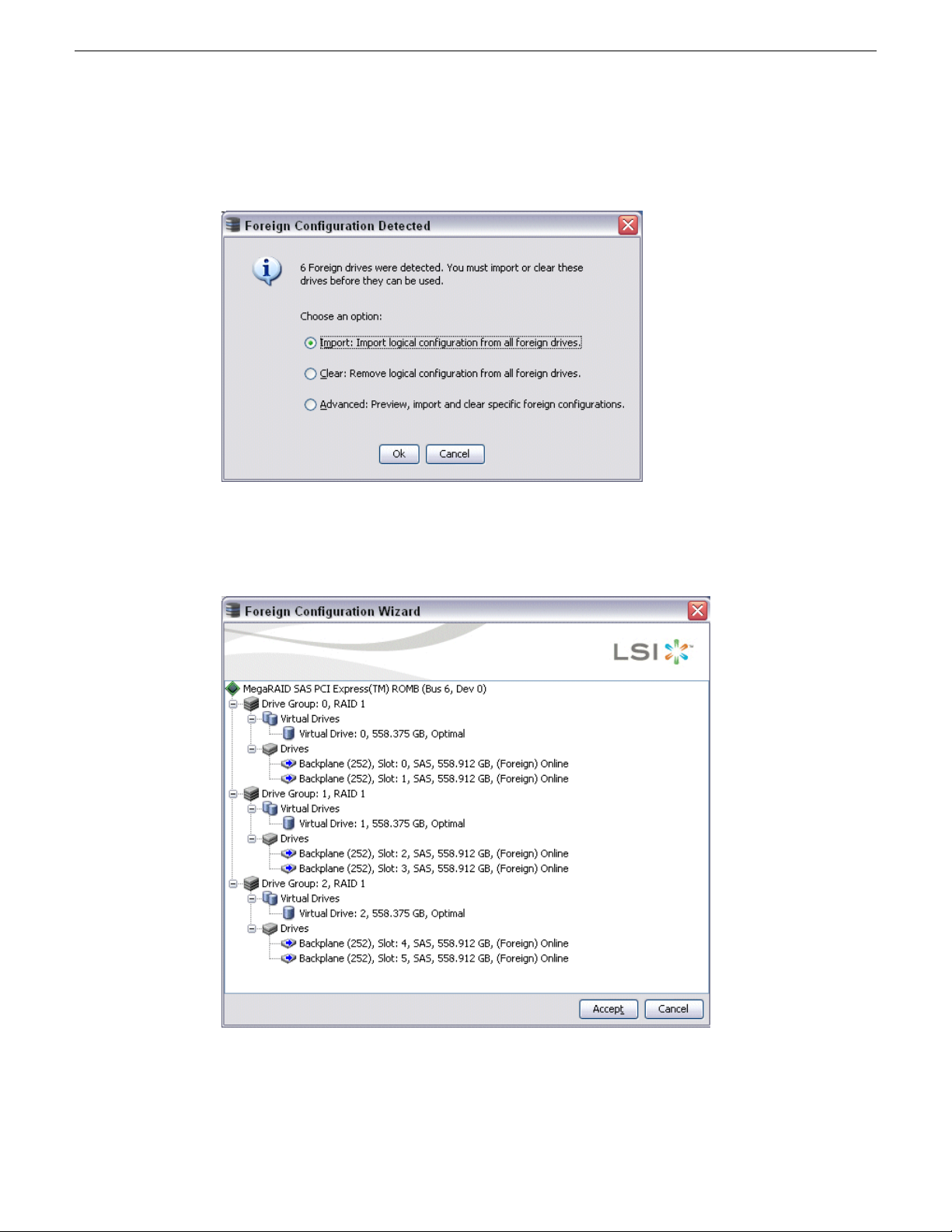
Service procedures
5. In the tree-view, right-click the top controller and select Scan For Foreign Configuration.
A Foreign Configuration Detected dialog box opens.
6. Make sure Import is selected and click OK.
A Foreign Configuration Wizard opens.
7. Click Accept.
8. When prompted "...import?", click Yes.
9. When informed "...imported successfully", click Yes.
66 K2 Summit 3G Production Client Service Manual 02 February 2012
Page 67

10. In the MegaRAID Storage Manager main window tree-view, verify that one controller reports
configured drives and one controller reports unconfigured drives.
11. For the controller with unconfigured drives, repeat previous steps to import the foreign
configuration.
12. When you have imported the foreign configuration for both controllers, click File | Exit to close
MegaRAID Storage Manager.
13. Restart the K2 Summit system.
Related Topics
Disk controller board removal on page 100
Recovering the media database
This section provides topics about recovering the media database.
About the automatic database backup process
Service procedures
Every 15 minutes the K2 system checks to see if any media operations have changed the media
database. If a change has occurred, the K2 system creates a backup file of the media database. The
backup file is saved in the same directory as the media database using a rotating set of three file
names. These files are named media.db_bakX where X is the number in the rotation. Each time a
backup occurs, the oldest backup file is overwritten. If some condition renders one of the backup
files un-writable, the backup file following that in the rotation is subsequently used for every backup
until the condition is resolved.
Identifying a corrupt media database
The following symptoms could indicate a corrupt media database:
• On startup, the Grass Valley MetaDataService is unable to start. This is indicated in the Services
control panel if the Grass Valley MetaDataService does not display as Started.
• The K2 log displays a “…file is encrypted or is not a database…” error.
As soon as you suspect a corrupt media database, stop all media access and take the K2 system
offline.
Restoring the media database
1. Stop all media access and take the K2 system offline.
2. Navigate to the V:\media directory.
3. Make a copy of the media.db and media.db_bak* files and store them in a secure location.
4. Stop the Grass Valley MetaDataService as follows:
For the standalone K2 system, use the Services control panel to stop the service.
5. Determine which backup file is the most recent good file by examining the file modification date
on each backup file.
6. Rename the current media.db file (which is assumed to be corrupt) to another name, and rename
the most recent good media.db_bakX file to media.db.
02 February 2012 K2 Summit 3G Production Client Service Manual 67
Page 68

Service procedures
7. Restart the K2 system following normal procedures.
8. Confirm that the systems come up correctly with the restored database now in place.
9. Use Storage Utility Clean Unreferenced Files and Clean Unreferenced Movies to repair any
Using recovery images
This section provides topics about using recovery images.
About the recovery image process
An image of the K2 Summit system system drive is provided with the product package. You can
restore the K2 Summit system from this image. This simplifies the process of rebuilding a system
in a disaster recovery scenario.
NOTE: This process is not intended as a means to backup and restore media.
When you receive your K2 Summit system new from the factory, you receive a system-specific
image for that particular K2 Summit system. This factory image is stored on a bootable USB Recovery
Flash Drive. Also on the Recovery Flash Drive is the Acronis True Image software necessary to
create and restore an image. You can find the Recovery Flash Drive in a holder in the front bezel
assembly.
inconsistencies between the contents of the database and the file system.
After your K2 Summit system is installed, configured, and running in your system environment,
you should create a new recovery image to capture settings changed from default. This “first birthday”
image is the baseline recovery image for the K2 Summit system in its life in your facility. There is
enough space on the Recovery Flash Drive to store the first birthday image along with the factory
image.
You should likewise create a new recovery image after completing any process that changes system
software or data, such as a software upgrade. In this way you retain the ability to restore your K2
Summit system to a recent “last known good” state.
You can also use the recovery image process on the control point PC.
NOTE: The recovery image process is an “off-line” process. Do not attempt this process while
media access is underway.
The recovery image process that you should follow is summarized in the following steps.
• At the K2 Summit system first birthday…
Boot from the Recovery Flash Drive.
Create a recovery image for the K2 Summit system.
Create a recovery image for the Control Point PC.
• At milestones, such as software upgrades…
Boot from the Recovery Flash Drive.
Create a recovery image for the K2 Summit system.
68 K2 Summit 3G Production Client Service Manual 02 February 2012
Page 69

• If you need to restore the K2 Summit system…
Boot from the Recovery Flash Drive.
Read the image from the Recovery Flash Drive or from the location that you stored the image.
• If you need to restore the Control Point PC…
Boot from the Recovery Flash drive.
Read the image from the location that you stored the image.
Use the following procedures to implement the recovery image process as necessary.
Creating a recovery image
Before creating a recovery image, determine the storage location for the image. Grass Valley
recommends that you store the recovery image on the Recovery Flash Drive, and this task provides
instructions for that location. If you use a different location, such as a network connected drive or
another connected USB drive, alter the steps in this task as appropriate.
1. Make sure that media access is stopped and that the system on which you are working is not
being used.
2. If you have not already done so, connect keyboard, monitor, and mouse.
3. Do the following:
a) Insert the Recovery Flash Drive into a USB port.
b) Restart the machine, or power on if currently shut down.
The machine boots from the Recovery Flash Drive, into a version of Windows stored on the
drive.
A MS-DOS command window opens.
Service procedures
c) When prompted with a list of options, type 2 to select the Acronis option and then press Enter.
The Acronis program loads.
4. In the Acronis main window, click Backup.
The Create Backup Wizard opens.
5. On the Welcome page, click Next.
6. On the Partitions Selection page, do the following:
a) Select the (C:) partition and then click Next.
NOTE: Verify capacity to make sure you select the boot media card (CompactFlash or
mSATA) and not a media drive. The boot media has a much smaller capacity.
If a “…choose full backup mode…” message appears, click OK.
02 February 2012 K2 Summit 3G Production Client Service Manual 69
Page 70

Service procedures
7. On the Backup Archive Location page, do the following:
8. On the Select Backup Mode page, select Create a new full backup archive and then click Next.
9. On the Backup Options page, do not change any settings. Click Next.
10. On the Archive Comment page, if desired, enter image comments such as the date, time, and
11. On the “…ready to proceed…” page, do the following:
a) in the tree view select Removable Disk (D:) and enter the name of the image file you are
creating.
Create the file name using the machine hostname and the date. Name the file with the .tib
extension.
For example, if the hostname is MySystem1, in the File name field you enter
A:\MySystem1_20121027.tib.
b) Click Next.
software versions contained in the image you are creating. Click Next.
a) Verify that you are creating an image from the C: drive and writing to the D:\ drive, then click
Proceed.
If a "...insert next volume..." message appears, click OK.
12. On the Operation Progress page, observe the progress report.
13. When a “Backup archive creation has been successfully completed” message appears, click OK.
14. Click Operations | Exit to exit the Acronis True Image program.
The machine restarts automatically.
15. Remove the recovery media while the machine is shutting down.
Restoring from a system-specific recovery image
Use this task to restore a K2 Summit system using an image made from that particular K2 Summit
system. If restoring from a generic factory default image, use the appropriate task.
Before restoring from a recovery image, make sure that the K2 Summit system has access to the
image from which you are restoring. This task provides instructions for accessing an image on the
Recovery Flash Drive. If you access an image from a different location, such as a network connected
drive or another connected USB drive, alter the steps in this task as appropriate.
1. Make sure that media access is stopped and that the system on which you are working is not
being used.
2. If you have not already done so, connect keyboard, monitor, and mouse.
3. Do the following:
a) Insert the Recovery Flash Drive into a USB port.
b) Restart the machine, or power on if currently shut down.
The machine boots from the Recovery Flash Drive, into a version of Windows stored on the
drive.
A MS-DOS command window opens.
c) When prompted with a list of options, type 2 to select the Acronis option and then press Enter.
The Acronis program loads.
70 K2 Summit 3G Production Client Service Manual 02 February 2012
Page 71

Service procedures
4. In the Acronis main window, click Recovery.
The Restore Data Wizard opens.
5. On the Welcome page, click Next.
6. On the Backup Archive Selection page, in the tree view expand the node for Removable Disk (D:)
and select the image file, then click Next.
7. On the Restoration Type Selection page, select Restore disks or partitions and then click Next.
8. On the Partition or Disk to Restore page, select MBR and Track 0 and then click Next.
9. On the Disk Selection page, select Disk 1 and then click Next.
NOTE: Verify capacity to make sure you select the boot media card. It has an interface
identified as "IDE (0) Primary Master".
10. On the Next Selection page, select Yes, I want to restore another partition or hard disk drive and
then click Next.
11. On the Partition or Disk to Restore page, select (C:) and then click Next.
12. On the Restored Partitions Resizing page, select Yes, I want to resize partitions and then click
Next.
13. On the Restored Location page, select (C:) and then click Next.
NOTE: Verify capacity to make sure you select the boot media card (CompactFlash or mSATA)
and not a media drive. The boot media has a much smaller capacity and has an interface
identified as "IDE (0) Primary Master".
14. On the Restored Partition Type page, select Active and then click Next.
15. Do one of the following:
• If the Restored Partition Size page does not appear. Skip ahead to the Next Selection page.
• If the Restored Partition Size page appears. Continue with the next step.
16. On the Restored Partition Size page, do one of the following:
• If Free space after reports 0 bytes, leave settings as they are. Click Next.
• If Free space after does not report 0 bytes, increase Partition size until Free space after reports
0 bytes. Click Next.
17. On the Next Selection page, select No, I do not and then click Next.
18. On the Restoration Options page, do not make any selections. Click Next.
19. On the “…ready to proceed…” page, verify that you are restoring the correct image to the correct
location. Click Proceed.
20. On the Operation Progress page, observe the progress report.
21. When a “The data was successfully restored” message appears, click OK.
22. Click Operations | Exit to exit the Acronis True Image program.
The machine restarts automatically.
23. Remove the recovery media while the machine is shutting down.
02 February 2012 K2 Summit 3G Production Client Service Manual 71
Page 72

Service procedures
Next, check the adapter names and order. If adapter names and order are not as documented, restore
network configuration.
Related Topics
Reorder adapters on page 60
Restoring network configuration on page 52
Restoring to blank mSATA
This task is for a K2 Summit 3G system that has had its mSATA boot media replaced with a new
blank mSATA card. This means the mSATA card has never been initialized and has never before
contained a disk image.
You can use this task to restore from a system-specific image or from a generic image. This task
provides instructions for accessing an image on the Recovery Flash Drive. If you access an image
from a different location, such as a network connected drive or another connected USB drive, alter
the steps in this task as appropriate. There can be multiple versions of the generic recovery disk
image on the Recovery Flash Drive. Refer to related topics in "K2 Release Notes" to determine
which version you should use.
NOTE: If restoring using a generic image, the K2 Summit system is returned to its factory
default condition. Passwords and other site-specific configurations are reset to factory defaults.
1. Make sure that media access is stopped and that the system on which you are working is not
being used.
2. If you have not already done so, connect keyboard, monitor, and mouse.
3. Do the following:
a) Insert the Recovery Flash Drive into a USB port.
b) Restart the machine, or power on if currently shut down.
The machine boots from the Recovery Flash Drive, into a version of Windows stored on the
drive.
A MS-DOS command window opens.
c) When prompted with a list of options, type 2 to select the Acronis option and then press Enter.
The Acronis program loads.
4. In the Acronis main window, click Recovery.
The Restore Data Wizard opens.
5. On the Welcome page, click Next.
6. On the Backup Archive Selection page, in the tree view expand the node for Removable Disk (D:)
and select the image file, then click Next.
7. On the Restoration Type Selection page, select Restore disks or partitions and then click Next.
8. On the Partition or Disk to Restore page, select MBR and Track 0 and then click Next.
9. On the Disk Selection page, select Disk 1 and then click Next.
NOTE: Verify capacity to make sure you select the boot media card. It has an interface
identified as "IDE (0) Primary Master".
10. On the Next Selection page, select Yes, I want to restore another partition or hard disk drive and
then click Next.
11. On the Partition or Disk to Restore page, select (C:) and then click Next.
72 K2 Summit 3G Production Client Service Manual 02 February 2012
Page 73

Service procedures
12. On the Restored Partitions Resizing page, select Yes, I want to resize partitions and then click
Next.
13. On the Restored Location page, select (C:) and then click Next.
NOTE: Verify capacity to make sure you select the boot media card (CompactFlash or mSATA)
and not a media drive. The boot media has a much smaller capacity and has an interface
identified as "IDE (0) Primary Master".
14. On the Restored Partition Type page, select Active and then click Next.
15. Do one of the following:
• If the Restored Partition Size page does not appear. Skip ahead to the Next Selection page.
• If the Restored Partition Size page appears. Continue with the next step.
16. On the Restored Partition Size page, do one of the following:
• If Free space after reports 0 bytes, leave settings as they are. Click Next.
• If Free space after does not report 0 bytes, increase Partition size until Free space after reports
0 bytes. Click Next.
17. On the Next Selection page, select No, I do not and then click Next.
18. On the Restoration Options page, do not make any selections. Click Next.
19. On the “…ready to proceed…” page, verify that you are restoring the correct image to the correct
location. Click Proceed.
20. On the Operation Progress page, observe the progress report.
21. When a “The data was successfully restored” message appears, click OK.
22. Click Operations | Exit to exit the Acronis True Image program.
The machine restarts automatically.
23. Remove the recovery media while the machine is shutting down.
Depending on whether you restored from a system-specific image or from a generic image, refer to
the appropriate disk image recovery task for next steps.
About saving and restoring settings while reimaging
If you are reimaging a K2 Summit 3G system with a generic disk image, you can run scripts to save
the media file system and other settings before the reimage, then restore the settings after the reimage.
Setting are saved and restored as follows:
• Media file system (SNFS): You run scripts to save and restore these settings. After the settings
are restored, on a standalone system you can access the media in the local media storage. On a
SAN-attached system, K2Config settings are restored so you can access media on the shared
media storage.
• SID, computer name, and network settings: You run the script to save settings to a text file, so
you can manually reconfigure as desired after the reimage.
If the media file system and settings are valid (not corrupt) on the K2 Summit 3G system before the
reimage, it is recommended that you use the save/restore scripts to save your media and settings,
thus saving time in the reimage process. However, if the media file system or settings are corrupt
02 February 2012 K2 Summit 3G Production Client Service Manual 73
Page 74

Service procedures
and your purpose for reimaging is to remove the corruption, it is likely that you do not want to use
the save/restore scripts.
Saving settings before generic reimage
1. If you are working on a K2 Summit SAN-attached system, on the K2 SAN’s control point PC,
2. Make sure you are logged in to the K2 Summit 3G system with administrator privileges.
3. Connect the USB Recovery Flash Drive to a USB port on the K2 Summit 3G system.
4. On the USB Recovery Flash Drive, navigate to the following location:
5. Run the following and wait for the process to complete:
6. Disconnect the USB Recovery Flash Drive.
use the K2Config application to remove the K2 Summit system from the SAN.
\tools\SaveRestoreScripts.
ssave.bat
This saves current settings onto the USB Recovery Flash Drive in the \settings directory.
Restoring from a generic image
This task can be used on a K2 Summit system that needs to be restored to its factory default state.
For example, if you neglected to make a first birthday image, you might need to use this procedure.
If the image from which you are restoring was made from the specific machine, refer to the
appropriate procedure.
This task provides instructions for accessing an image on the Recovery Flash Drive. If you access
an image from a different location, such as a network connected drive or another connected USB
drive, alter the steps in this task as appropriate. There can be multiple versions of the generic recovery
disk image on the Recovery Flash Drive. Refer to related topics in "K2 Release Notes" to determine
which version you should use.
NOTE: This procedure restores the K2 Summit system to its factory default condition. Passwords
and other site-specific configurations are reset to factory defaults.
1. Make sure that media access is stopped and that the system on which you are working is not
being used.
2. If you have not already done so, connect keyboard, monitor, and mouse.
3. Do the following:
a) Insert the Recovery Flash Drive into a USB port.
b) Restart the machine, or power on if currently shut down.
The machine boots from the Recovery Flash Drive, into a version of Windows stored on the
drive.
A MS-DOS command window opens.
c) When prompted with a list of options, type 2 to select the Acronis option and then press Enter.
The Acronis program loads.
4. In the Acronis main window, click Recovery.
The Restore Data Wizard opens.
74 K2 Summit 3G Production Client Service Manual 02 February 2012
Page 75

Service procedures
5. On the Welcome page, click Next.
6. On the Backup Archive Selection page, in the tree view expand the node for Removable Disk (D:)
and select the image file, then click Next.
7. On the Restoration Type Selection page, select Restore disks or partitions and then click Next.
8. On the Partition or Disk to Restore page, select MBR and Track 0 and then click Next.
9. On the Disk Selection page, select Disk 1 and then click Next.
NOTE: Verify capacity to make sure you select the boot media card. It has an interface
identified as "IDE (0) Primary Master".
10. On the Next Selection page, select Yes, I want to restore another partition or hard disk drive and
then click Next.
11. On the Partition or Disk to Restore page, select (C:) and then click Next.
12. On the Restored Partitions Resizing page, select Yes, I want to resize partitions and then click
Next.
13. On the Restored Location page, select (C:) and then click Next.
NOTE: Verify capacity to make sure you select the boot media card (CompactFlash or mSATA)
and not a media drive. The boot media has a much smaller capacity and has an interface
identified as "IDE (0) Primary Master".
14. On the Restored Partition Type page, select Active and then click Next.
15. Do one of the following:
• If the Restored Partition Size page does not appear. Skip ahead to the Next Selection page.
• If the Restored Partition Size page appears. Continue with the next step.
16. On the Restored Partition Size page, do one of the following:
• If Free space after reports 0 bytes, leave settings as they are. Click Next.
• If Free space after does not report 0 bytes, increase Partition size until Free space after reports
0 bytes. Click Next.
17. On the Next Selection page, select No, I do not and then click Next.
18. On the Restoration Options page, do not make any selections. Click Next.
19. On the “…ready to proceed…” page, verify that you are restoring the correct image to the correct
location. Click Proceed.
20. On the Operation Progress page, observe the progress report.
21. When a “The data was successfully restored” message appears, click OK.
22. Click Operations | Exit to exit the Acronis True Image program.
The machine restarts automatically.
23. Remove the recovery media while the machine is shutting down.
24. Upon startup, wait for initialization processes to complete. This can take several minutes, during
which time USB keyboard/mouse input is not operational. Do not attempt to shutdown or
otherwise interfere with initialization processes.
After startup, one or more device discovery windows can open. Allow processes to complete
without interference. If a Fibre Channel card driver, ignore until instructed later in this process.
02 February 2012 K2 Summit 3G Production Client Service Manual 75
Page 76

Service procedures
Next, check the adapter names and order. If adapter names and order are not as documented, restore
network configuration.
Restoring settings after generic reimage
This task assumes that you have saved settings using ssave.bat before reimaging the K2 Summit
3G system, and that the reimage (Acronis) process is complete.
1. If you have not already done so, start up the K2 Summit 3G system and log on with administrator
2. Connect the USB Recovery Flash Drive to a USB port on the K2 Summit 3G system.
3. From the USB Recovery Flash Drive, run the following and wait for the process to complete:
4. If desired, name the computer (My Computer).
5. Run the following:
privileges.
The administrator password is adminGV!.
srestore.bat
You can copy the name from C:\README.txt.
C:\WINDOWS\NewSid\newsid.exe
The New SID wizard opens.
6. In the New SID wizard, do one of the following:
• To allow the wizard to assign a new, random SID to the K2 Summit 3G system, select Random
SID.
• To retain the SID that the K2 Summit 3G system had before reimaging, select Specify SID.
Refer to C:\README.txt to get the SID and instructions on entering the SID.
7. In the New SID wizard, select Rename the computer to: and enter the computer name.
8. Click Next to complete the wizard.
The K2 Summit 3G system restarts.
Next, do the following as appropriate to restore your K2 Summit 3G system. Refer to related topics
in this document or as otherwise indicated.
1. Restore network configuration. If you saved settings with ssave.bat, refer to C:\ipconfig.txt
for the complete listing of the network settings that the K2 Summit 3G system had before
reimaging.
2. Check the Windows operating system clock, and if necessary, set it to the correct time.
3. Install K2 software and SNFS software. If you saved/restored settings with ssave.bat and
srestore.bat, SNFS uses the restored settings. Refer to related topics in "K2 Release Notes".
4. Install the SiteConfig Discovery Agent.
5. If the K2 Summit system has a Fibre Channel card, install the Fibre Channel Card driver. Refer
to related topics in this document.
6. If a K2 Summit system with direct-connect storage or shared storage on a redundant K2 SAN,
install MPIO software.
7. If a K2 Summit SAN-attached system, on the K2 SAN’s control point PC, use the K2Config
application to add the K2 Summit system back to the SAN
76 K2 Summit 3G Production Client Service Manual 02 February 2012
Page 77

8. Restore SabreTooth licenses.
9. Activate Windows within 30 days.
Installing the Discovery Agent on a K2 Summit system
If the device that you plan to manage with SiteConfig does not have a SiteConfig Discovery agent
installed, use this topic to verify and, if necessary, manually install SiteConfig support software.
Doing so allows SiteConfig to discover and manage the device. If the device has any version of the
SiteConfig Discovery Agent currently installed, you should use SiteConfig to upgrade the Discovery
Agent, rather than installing it manually.
1. On the device you plan to manage with SiteConfig, open the Windows Services Control Panel
and look for the following required item:
• ProductFrame Discovery Agent
2. Proceed as follows:
• If you find the required items, no further steps are necessary. SiteConfig support software is
installed.
• If a required item is not present, navigate to your SiteConfig files. If you do not already have
these files in convenient location, you can find them on the PC that hosts SiteConfig, in the
SiteConfig install location. Then continue with next steps as appropriate.
Service procedures
3. To launch the program that installs the ProductFrame Discovery Agent Service do the following:
a) Copy the Discovery Agent Setup subdirectory to the device.
b) In the Discovery Agent Setup directory, double-click the
DiscoveryAgentServiceSetup.msi file.
The setup program launches to install the SiteConfig Discovery Agent.
c) Follow the setup wizard.
4. When presented with a list of device types, select one of the following as appropriate:
• K2SummitSanClient
• K2SummitStandaloneClient
5. Complete the setup wizard and restart the device.
The restart is required after the installation.
Installing the ATTO Fibre Channel card driver
Before installing the Fibre Channel card driver, make sure that K2 software is installed and the write
filter is disabled. Also, if the K2 Summit system is on a redundant K2 SAN or is connected to
direct-connect storage, make sure that MPIO software is installed.
If your K2 Summit system has the optional Fibre Channel card, the driver for the Fibre Channel
card is not installed on the recovery image provided by Grass Valley for that K2 Summit system.
Therefore, after restoring the image, you must install the Fibre Channel card driver.
1. Open Device Manager.
2. Right-click on K2 Summit Client and select Manage.
02 February 2012 K2 Summit 3G Production Client Service Manual 77
Page 78

Service procedures
3. Click Device Manager
4. Install the first Fibre Channel driver as follows:
5. Repeat the process for the second Fibre Channel Controller as follows:
a) Right click on the upper Fibre Channel Controller and select Update Driver…
b) On the Welcome page, select No, not this time and then click Next.
c) Select Install from a list or specific location and then click Next.
d) Browse to C:\Profile\Drivers\ Atto 8Gb HBA Drivers\x86.
e) Click OK.
f) Click Next.
g) Click Finish when prompted.
h) In the Found new hardware wizard that will open for the ATTO Phantom device, select No,
not this time.
i) Select Install from a list or specific location and then click Next.
j) Browse to C:\Profile\Drivers\ Atto 8Gb HBA Drivers\x86.
k) Click OK .
l) Click Next..
m) Click Finish when prompted.
a) Right-click on the remaining Fibre Channel Controller and select Update Driver…
b) On the Welcome page, select No, not this time and then click Next.
c) Select Install from a list or specific location and then click Next.
d) Browse to C:\Profile\Drivers\ Atto 8Gb HBA Drivers\x86.
e) Click OK.
f) Click Next.
g) Click Finish when prompted.
6. Verify that the two "ATTO" devices are now listed under the SCSI and RAID Controllers
7. Close the Device Manager and System windows
Using diagnostic tools
Use the following sections as necessary to identify problems.
Running Check Disk
If your K2 Summit 3G system has a critical system fault, you should run Check Disk to identify
and remove any corrupted files.
1. Make sure the K2 Summit 3G system has no media access currently underway.
2. At the MS-DOS command prompt, enter the following and press Enter.
chkdsk
Check Disk reports file system information and lists any problem found.
78 K2 Summit 3G Production Client Service Manual 02 February 2012
Page 79

Service procedures
3. Do one of the following:
• If Check Disk does not report any problems, close the command prompt window. Do not
complete the remaining steps of this procedure.
• If Check Disk reports a problem and prompts you to repair, continue with this procedure.
4. When prompted to repair problems, do the following:
a) Press the Y key and then press Enter.
b) Enter the following and press Enter.
chkdsk /F
The screen displays a message similar to the following:
...Cannot lock current drive. Chkdsk cannot run because the volume
is in use by another process. Would you like to schedule this volume
to be checked the next time the system restarts? (Y/N)
c) Press the Y key and then press Enter.
5. Restart the K2 Summit 3G system.
Running diagnostics for K2 Summit 3G system
If you suspect a problem with K2 Summit 3G system hardware, you can run diagnostics and check
for errors.
1. Make sure all media access is stopped on the K2 Summit 3G system. Also make sure that there
is nothing preventing a restart, as it is required after you run diagnostics.
2. From the Windows desktop, click Start | All Programs | Grass Valley | Diagnostics.
The Summit Diagnostics application opens.
02 February 2012 K2 Summit 3G Production Client Service Manual 79
Page 80

Service procedures
3. Click Start.
The Overall Result indicator displays RUN while diagnostics are underway.
When diagnostics complete, the Overall Result indicator reports results as follows:
• PASS – There are no problems reported in the diagnostic logs.
• FAIL – There are one or more problems reported in one or more diagnostic logs.
4. To view a diagnostic log, in the Components list, select a log.
The log's contents appear in the Log pane.
5. To close the Summit Diagnostics application, allow any currently running diagnostics to complete,
then click the window close button (X) in the upper right corner of the application window.
A "...should be restarted..." message appears.
6. Click OK and then restart the K2 Summit 3G system.
You must restart before you can use the K2 Summit 3G system. Running diagnostics puts the
real time processor and other services in a non-production state.
80 K2 Summit 3G Production Client Service Manual 02 February 2012
Page 81

Chapter 4
Troubleshooting problems
This section contains the following topics:
• Step 1: Check configurations
• Step 2: Check connections and external equipment
• Step 3: Check system status messages
• Step 4: Identify problems using the startup sequence
• Shutdown/restart problems
• Checking external equipment
• Power connection sequence
• BIOS startup
• Windows startup
• K2 Summit system startup
• Windows startup problems
• Thermal problems
• Codec board problems
• Power supply problems
• Video problems
• Audio problems
• Timecode problems
• Operational problems
• System problems
• Storage problems
• Network, transfer, and streaming problems
02 February 2012 K2 Summit 3G Production Client Service Manual 81
Page 82

Troubleshooting problems
Step 1: Check configurations
Many times what appears to be a K2 Summit system fault is actually an easy-to-fix configuration
problem. Check settings in Configuration Manager and verify that the system is configured as you
expect. Refer to related topics in "K2 AppCenter User Manual" and "K2 System Guide".
Step 2: Check connections and external equipment
Loose or improperly connected cables are the most likely source of problems for the system. A
quick check of all the cable connections can easily solve these problems. Refer to related topics in
"K2 System Guide" for help with making connections. Check external equipment if you suspect a
failure in a device connected to the K2 Summit system.
Related Topics
Checking external equipment on page 84
Step 3: Check system status messages
While the K2 Summit system is in operation, some problems are detected and reported in system
status messages. To view system status messages, in AppCenter select Help | System Status.
When connecting to a K2 Summit system from a control point PC using remote AppCenter, if there
is an AppCenter system startup error, the error is reported during the connection attempt.
If the system status message indicates a problem, refer to related topics in this document.
NOTE: Do not use the MegaRAID utility on a K2 Summit system. This utility is for use by
qualified Grass Valley Service personnel only. When this utility is opened it scans the SCSI bus
and interferes with record and play operations.
Related Topics
Viewing AppCenter system status messages on page 43
Step 4: Identify problems using the startup sequence
The startup sequence is your primary tool for identifying a K2 Summit system fault. As the different
levels of the K2 Summit system system become operational in the startup process, the primary
components of the system are checked. You can identify most problems by evaluating the messages
and other indicators that occur during the startup sequence.
NOTE: This procedure assumes that the K2 Summit system is not in Storage Utility’s “offline”
mode.
To identify problems using the startup sequence, do the following:
1. Connect mouse, keyboard, and monitor. You must observe the VGA screen and be able to interact
with the system via keyboard and mouse to fully identify problems.
2. Restart the K2 Summit system.
82 K2 Summit 3G Production Client Service Manual 02 February 2012
Page 83

Troubleshooting problems
3. Once the startup sequence begins, observe the progression of behaviors as listed in the following
table. These are the behaviors you should expect for a normally operating K2 Summit system.
If you observe behaviors other than those listed, refer to the indicated troubleshooting topics to
identify problems.
NOTE: You can press the Pause/Break key on the keyboard to keep startup text on the screen
for longer viewing.
If not, refer to the following:This behavior should occur…At about
this time…
—
Pressing the standby button starts the K2 Summit
system.
Power on LED goes on and stays on.0 seconds
Service LED stays off.
Front bezel assembly and processor fan start.
seconds
seconds
seconds
Logon to Windows to continue the startup sequence.
After Windows logon:
this time…
Shutdown/restart problems on
page 84
Power supply problems on page
87
Shutdown/restart problems on
page 84
Windows startup problems on
page 86
BIOS startup on page 85System BIOS screen appears.10
—Grass Valley logo screen appears.35
Windows startup on page 85Windows logon screen appears.70
If not, refer to the following:This behavior should occur…At about
K2 Summit system startup on
page 86
Windows startup on page 85, K2
Summit system startup on page
20
seconds
Grass Valley logo desktop appears.0 seconds
Service LED goes on for a few seconds, then off.5 seconds
Desktop icons, startbar, and AppCenter logon
box appear.
86
Logon to AppCenter to continue the startup sequence.
After AppCenter logon:
If not, refer to the following:This behavior should occur…At about
this time…
System Startup messages appear.0 seconds
K2 Summit system startup on
page 86
02 February 2012 K2 Summit 3G Production Client Service Manual 83
Page 84

Troubleshooting problems
this time…
If not, refer to the following:This behavior should occur…At about
Time
varies.
Between
AppCenter opens. Media operations are
functional.
30
seconds
and 2
minutes.
Shutdown/restart problems
If the K2 Summit system is inoperable due to an error it can affect the operation of the standby
button. If pressing the standby button does not shut down the K2 Summit system, press and hold
the button for five seconds. This forces the K2 Summit system to execute a hard power down. If
that doesn't work or if after the hard power down the system does not boot, disconnect then reconnect
the power cable(s).
The K2 Summit system is set to attempt to boot from a USB drive first, before it boots from the
boot media card. If you have a drive connected to a USB port that does not contain an appropriate
operating system and you start up the K2 Summit system, an error message is displayed and the
boot up process halts.
Operational problems on page 90All system components check out as OK and
Checking external equipment
This section provides troubleshooting procedures for external devices that connect to the K2 Summit
system. Before using these procedures, first check connections.
Related Topics
Step 2: Check connections and external equipment on page 82
VGA display problems
Screen turns on, but nothing
from K2 Summit system is
displayed.
Keyboard and mouse problems
The keyboard and mouse are detected during BIOS startup. There should be a very brief message
displayed indicating detection of input devices connected to USB ports
connected or is faulty.
K2 Summit system system
settings have been tampered
with.
Corrective ActionsPossible CausesProblem
Replace VGA monitor.VGA connector or cable is not
Restore default settings by
restoring the system drive image
from a recent backup image.
84 K2 Summit 3G Production Client Service Manual 02 February 2012
Page 85

not respond correctly when one
or more of the keys on the
keyboard are pressed or the
mouse is used.
Power connection sequence
The following table lists the sequence of behaviors you should expect to see and/or hear as you
connect the first power cable to a normally operating K2 Summit system. If you observe behaviors
other than those listed, refer to related topics in this document to investigate potential problems.
K2 Summit system system
settings have been tampered
with.
Troubleshooting problems
Corrective ActionsPossible CausesProblem
Replace the keyboard or mouse.The keyboard or mouse is faulty.The K2 Summit system does
Restore default settings by
restoring the system drive image
from a recent backup image.
In this
time…
This power connection sequence assumes that before power was removed, the K2 Summit system
was properly shut down from AppCenter, from the Windows operating system, or from the standby
button. If the power was removed without a proper shutdown, when the first power cord is connected
the K2 Summit system might go directly to the startup sequence.
Related Topics
Shutdown/restart problems on page 84
BIOS startup
A few seconds after startup, on the VGA monitor a screen displays BIOS information, with
instructions about how to access settings. While this information is displayed, press the key on the
keyboard as instructed to enter the BIOS settings pages. When the BIOS completes the Windows
operating system begins to load.
If during the BIOS time a message appears that requires your input or if the K2 Summit system
does not progress to Windows startup, it indicates a problem at the motherboard level. To correct
problems of this nature, contact Grass Valley Support.
If not, refer to the following.On the K2 Summit system front panel or
chassis, look/listen for the following…
Power supply problems on page 87Power supply fans go on and stay on.0 seconds
Power on LED goes on and stays on.
Media disk problems on page 92Drive busy LED goes on then off.
Windows startup
After the host startup processes complete the Windows operating system starts up. Normally the
Windows operating system completes its processes automatically without the need to press keys or
respond to messages. When the Windows startup is complete the Windows logon dialog box is
displayed.
02 February 2012 K2 Summit 3G Production Client Service Manual 85
Page 86

Troubleshooting problems
If the Windows startup screen does not proceed automatically or if a message appears that requires
your input, it indicates a problem at the operating system level. If the problem cannot be corrected
with a supported procedure (such as networking), the Windows operating system is not operating
as it should. To correct problems of this nature, restore the system drive image.
Related Topics
Windows startup problems on page 86
Using recovery images on page 68
K2 Summit system startup
After the Windows operating system startup processes complete, you must log in to AppCenter to
trigger K2 Summit system startup processes to begin. The K2 Summit system determines that system
health is adequate by checking critical subsystems. Critical subsystems are those upon which the
K2 Summit system depends for core media functionality. Critical subsystem checks are displayed
in the System Startup message box.
When all critical subsystem checks are successful, AppCenter opens. If a critical error occurs, a
message appears and AppCenter does not open. You can check the list of the messages that can
appear.
To correct problems revealed at system startup, use the indicated troubleshooting information from
the following sections.
Related Topics
Critical system startup messages on page 42
Windows startup problems
A “Non-system disk. Press any
key to restart” message appears.
A non-bootable USB drive is
connected.
The boot media is corrupted.
Corrective ActionsPossible CausesProblem
Remove the USB drive, then
press any key to continue.
Restore from the USB Recovery
Flash Drive.
86 K2 Summit 3G Production Client Service Manual 02 February 2012
Page 87

Thermal problems
Troubleshooting problems
Corrective ActionsPossible CausesProblem
The K2 Summit system
overheats. This can be
accompanied by a StatusPane
message indicating a
temperature or fan problem.
Related Topics
Front bezel assembly removal on page 98
Codec board problems
Investigate the problem further as described in the following table. If the problem persists, contact
Grass Valley Support.
A system status message
indicates a problem with the
codec board.
Airflow is blocked. The fan
module is not operating
correctly.
The codec module is not
connected properly or is faulty.
Ensure adequate airflow around
the K2 Summit system. Inspect
the fans in the front bezel
assembly and its connections for
proper operation. If the fans are
not operating correctly, replace
the front bezel assembly.
Corrective ActionsPossible CausesProblem
Check the codec board indicator
(LED) on the rear panel.
Visually inspect codec module.
Make sure it is connected
properly and there is no sign of
physical damage. Restart the K2
Summit system. If the problem
persists, replace the codec
module.
Related Topics
Codec module removal on page 102
Power supply problems
Corrective ActionsPossible CausesProblem
The power source is faulty.The K2 Summit system will not
power on or power fails while
the K2 Summit system is in
operation. This can be
A power cord is faulty.
accompanied by a StatusPane
message indicating a power
supply problem prior to the
failure.
02 February 2012 K2 Summit 3G Production Client Service Manual 87
Make sure your power source is
reliable.
Both power supplies run and the
K2 Summit system can operate
with just one power cord
connected. Connect one power
cord at a time and test with a
replacement cord.
Page 88

Troubleshooting problems
Corrective ActionsPossible CausesProblem
Power supply “~AC” LED is
amber
The K2 Summit system is too
hot. The built-in
overtemperature protection can
shut down the power supply.
is indicated if the front panel
power indicator does not come
on.
Over temperature due to air flow
restriction.
Over temperature due to power
supply fan failure.
Over current, under voltage,
over voltage. These conditions
could be caused by a faulty FRU
module.
Check for thermal problems.
Cool the K2 Summit system.
Replace the power supply.The power supply is faulty. This
Check for and remove any air
flow blockage around the power
supply.
Visually inspect fan. Listen for
fan noise. If faulty, replace
power supply.
Disengage all FRU modules,
then re-engage one at time. If
one module causes the amber
LED to go on, replace the
module. If both power supplies
have the amber LED, disengage
one, then the other. If doing so
results in just one power supply
having the amber LED, replace
that power supply.
Related Topics
Power supply module removal on page 102
Video problems
For the corrective actions in this section, refer to related topics in "K2 AppCenter User Manual" for
detailed instructions.
The picture level modulates at
a particular frequency.
In stop mode the still-play
video shows some motion jitter.
The video displays erratically
moving green lines.
There is distortion in the video
input signal.
Two fields are displayed in still
play mode.
K2 Summit system is not locked
to a video reference.
Corrective ActionsPossible CausesProblem
Check the video input signal for
distortion. Compare with test
color bars and audio test tone.
Switch the still-play mode
setting to Field.
Lock the K2 Summit system to
a video reference.
88 K2 Summit 3G Production Client Service Manual 02 February 2012
Page 89

Audio problems
For the corrective actions in this section, refer to related topics in "K2 AppCenter User Manual" for
detailed instructions.
Troubleshooting problems
Corrective ActionsPossible CausesProblem
Select the correct audio input.Wrong audio input selected.No record audio.
No embedded audio.
Playback audio output is
distorted.
The audio level is not correct
only when playing a particular
clip.
display the correct reference
level on connected equipment.
Audio meters do not appear in
the AppCenter Monitor Pane.
Video source does not have
embedded audio.
Audio input signal clipping
caused by excessive audio input
level.
Audio level needs to be adjusted.Audio level is too low.
The clip’s audio level is out of
adjustment.
Incorrect audio reference level.Audio level meters do not
The Monitor Pane configured to
not display audio meters.
Check your video source for
embedded audio.
Check for input audio clipping.
Adjust the audio input trim.
Adjust the Player audio level.
Reduce the source audio input
level.
Adjust the Player or Recorder
audio level. Increase the source
audio input level.
Load the clip in Player and
adjust its playback audio level.
Select the correct audio
reference level.
Configure the Channel
Monitoring setting to display
audio meters.
Timecode problems
For the corrective actions in this section, refer to related topics in "K2 AppCenter User Manual" for
detailed instructions.
Corrective ActionsPossible CausesProblem
Recorded timecode reads
xx.xx.xx.xx.
A clip shows no
mark-in/mark-out timecode, the
current timecode display shows
XX:XX:XX:XX, or the last
valid timecode is displayed.
02 February 2012 K2 Summit 3G Production Client Service Manual 89
During recording, the channel
had no timecode source.
The selected timecode source
was missing or intermittent
during recording.
Check that you have the right
record channel timecode source
selected, verify that timecode is
present in the source, and record
the clip again. You can also
stripe the timecode on an
existing clip.
Page 90

Troubleshooting problems
Operational problems
For the corrective actions in this section, refer to related topics in "K2 AppCenter User Manual" for
detailed instructions.
Corrective ActionsPossible CausesProblem
Moving video in AppCenter
does not operate.
modification, configuration
setting, or other change is lost.
The K2 Summit system is not
operating as expected in
relation to a setting displayed
in Configuration Manager.
AppCenter displays different
buttons than those expected.
A clip does not play, even
though other clips play on the
same channel.
The K2 Summit system is not
licensed for AppCenter Pro.
The VGA monitor resolution is
less than 1024x768x32.
Remote Desktop.
The write filter is enabled.After restarting, a file
The setting was changed in
Configuration Manager but not
saved to the database.
Assignable buttons have been
changed.
The clip does not match current
K2 Summit system settings or
the clip is corrupt.
Obtain an AppCenter Pro
license.
Configure VGA monitor
resolution. The resolution must
be at least 1024x768x32 to
support live video.
Restart AppCenter.Another user is connected via
Disable the write filter, make the
change that you want to make
permanent, then enable the write
filter.
Verify the setting you want in
Configuration Manager and then
select OK. When prompted to
change the system settings,
select Yes.
Assign buttons to the interface
as desired.
If the clip appears grayed-out it
means it doesn’t match current
settings. Check the clip’s
properties and verify they are
correct for the standard,
compression, and other current
settings. Compare properties
with those of a clip that plays
correctly. If properties are
correct the clip is corrupt. Delete
and re-record the clip.
Verify licensing.The K2 system is not licensed
for the format of the clip.
Unlock the clip.The clip is locked.A clip can not be edited.
Can’t rename a clip or modify
mark-in/mark-out points
90 K2 Summit 3G Production Client Service Manual 02 February 2012
being recorded. In this case,
“Read-Only” is displayed in the
StatusBar.
The list contains invalid clips.Cannot load and play a list.
Wait until recording is complete.The clip loaded or playing is still
Check format, licensing, and
security setting of the clips in the
list.
Page 91

subclip is automatically
generated and ejected, and a
new subclip name is loaded in
the subclip pane.
Troubleshooting problems
Corrective ActionsPossible CausesProblem
Disable Auto Subclip mode.Auto Subclip mode is enabled.On setting mark-out, the
Can’t change what information
is displayed in the Monitor
Pane for Playlist.
Can’t control a channel from
AppCenter. Controls are
disabled.
System problems
For the corrective actions in this section, refer to related topics in "K2 AppCenter User Manual" for
detailed instructions.
One of the record channels does
not record or video is jumpy.
A scheduled event, such as an
automatic play or record event,
does not occur at the proper
time.
You are attempting to use
Configuration Manager to
change what information is
displayed in Monitor Pane for
Playlist.
The channel is configured for
control by a remote control
protocol.
The K2 Summit system is
configured for PAL, yet the
video input is NTSC
The time-of-day source for event
scheduling is not accurate.
Use the Playlist Options dialog
instead.
Set the control mode for limited
local control.
Corrective ActionsPossible CausesProblem
Check the current setting for
video standard. Verify that the
video input signal is the correct
standard.
Verify the time-of-day source.
Verify the source’s time
accuracy.
Storage problems
Use the following sections if you suspect problems with your K2 Summit system’s storage. Refer
to related topics in "K2 System Guide" for Storage Utility procedures.
02 February 2012 K2 Summit 3G Production Client Service Manual 91
Page 92

Troubleshooting problems
Media File System problems
Corrective ActionsPossible CausesProblem
One or more clips do not play
or record correctly. This can be
accompanied by a StatusPane
message indicating a fault in
the media file system.
During K2 Summit system
startup a “…no file system
running…” message appears.
Related Topics
Checking the storage system on page 93
Media disk problems
On the Windows desktop open the "My Computer" for you K2 system and do a quick check of the
drives. You should see C: and V: drives.
The media database is out of
sync with the media files or
there is a corrupt media file.
Also check the storage system
for causes related to certain
usage patterns.
The file system is corrupt or
disks are faulty/missing such
that they are not part of a stripe
group.
1. If the problem is only
associated with a specific clip or
clips, delete the problem clips.
If the problem persists, proceed
with the next step.
2. Use Storage Utility and Check
File System. If the file system
fails the check process you must
make a new file system. When
you do so you lose all media.
Use Storage Utility and Check
File System. If the file system
fails the check process you must
make a new file system. When
you do so you lose all media.
Corrective ActionsPossible CausesProblem
No clips appear in the Clips
pane. This may be
accompanied by a startup
A media disk is bad or
there has been a
hardware failure.
Open Storage Utility and identify faulty
disks. Replace faulty disks.
message or a StatusPane
message regarding media
disks being unavailable.
The StatusPane message
“Media disks getting full…”
appears or a “FSS
‘default(0)’” message
appears.
The media disks are
reaching maximum
capacity.
In Recorder, select the Time Dome and
choose Available Storage. If the Time Dome
is filled it confirms that your K2 Summit
system is out of space. Make space on the
media drives by doing the following:
- Delete unused clips and empty the Recycled
Bin.
92 K2 Summit 3G Production Client Service Manual 02 February 2012
Page 93

Troubleshooting problems
Corrective ActionsPossible CausesProblem
When streaming to another
K2 Summit system the
operation fails. In Transfer
Monitor the streaming
operation shows
“Status:Error”.
System status message “File
system…is fragmented”.
Related Topics
Replacing a RAID 1 drive on page 51
Checking the storage system
The following section provides guidelines for investigating problem areas related to the storage
system. Use this section if you have problems with media input and/or output that are intermittent
or seem to be related to certain usage patterns.
There is a network
connection error or the
media disks at the
destination are
reaching maximum
capacity.
Extended record/play
activity has
fragmented the disks.
Check network connections and
configuration. Check available storage on
the destination K2 Summit system. In
Recorder, select the Time Dome and choose
Available Storage. If the Time Dome is filled
it confirms that the destination K2 Summit
system is out of space. Make space on the
media drives by deleting unused clips and
emptying the Recycle Bin.
Use the Storage Utility to check the file
system.
02 February 2012 K2 Summit 3G Production Client Service Manual 93
Page 94

Troubleshooting problems
Corrective ActionsPossible CausesProblem
Symptoms can include
black video recorded or at
playout, frozen video, slow
performance, or
inconsistent media access.
These symptoms can be
accompanied by StatusPane
messages regarding disk
problems or
overrun/underrun
conditions for encoders,
decoders, or timecode.
The following causes can occur on
their own or in combination to
produce the problem:
• Disk oversubscription — This
occurs when requests to the
media disk exceed the disk’s
bandwidth capabilities. This
generally occur in extreme cases
when a combination of
high-bandwidth operations are
taking place, such as jog/shuttle,
record/play on multiple
channels, or streaming multiple
clips.
• High CPU activity in Windows
— This occurs when activities
on the Windows operating
system over-tax the capabilities
of the CPU. This commonly
happens when unsupported
software has been installed that
competes with K2 Summit
system applications. Virus
scanners and screen savers can
cause this type of problem, since
they can start automatically and
consume system resources.
• Encoder overrun — This occurs
when an encoder is flooded with
more data than it can process
within its real-time requirements
for recording.
• Decoder underrun — This
occurs when a decoder is starved
for data and cannot deliver
enough to satisfy real-time
requirements for playout.
• Disk faults — This occurs when
a media disk is severely
fragmented or has a bad blocks
that interfere with some, but not
all, media operations. For
example, a particular clip can be
written on a bad block, so the
problem occurs only on that clip.
Try to re-create the problem.
Identify all the interactions that
affected the system and run all
the same operations as when the
error occurred.
Record/play/stream the same
clips. Investigate the functions
that seem to push the system into
the error state. If you determine
that certain simultaneous
operations cause the problem,
re-order your workflow to avoid
those situations. If you determine
that the problem is only on
certain clips, investigate disk
faults.
94 K2 Summit 3G Production Client Service Manual 02 February 2012
Page 95

Network, transfer, and streaming problems
Remember to disable the write filter before making changes and enable the write filter after making
changes.
Troubleshooting problems
Corrective ActionsPossible CausesProblem
When importing or exporting
(sending) between K2 Summit
systems a “…failed to
connect…” message appears
and the operation fails.
There is a problem with
Windows networking or there is
a mis-spelling with the host
name as entered in
Configuration Manager.
The K2 Summit system to which
you are trying to connect is not
operating or the network is
mis-configured.
Check networking as follows:
- Check basic Windows
networking. Use Windows
Explorer to test a basic copy
operation to the machine to
which you are trying to connect.
If basic networking fails, use
standard Windows procedures
to troubleshoot and correct your
network.
- If the Windows network is
working properly, in AppCenter
select System | Configuration |
Remote and verify that the name
of the machine to which you are
trying to connect is spelled
correctly and has no extra spaces
or characters.
Verify that the K2 Summit
system to which you are trying
to connect is operational and that
the network is configured
correctly. Verify that the name
of the K2 Summit system is
entered correctly in the
Configuration Manager Hosts
page. Refer to networking topics
in "K2 System Guide".
A networked device does not
appear in the “Import” and
“Send to” dialog boxes, even
though it is present on the
Windows network.
The device is not entered as a
host.
In AppCenter select System |
Configuration | Remote | Add and
enter the name of the machine
to which you are trying to
connect. Make sure it is spelled
correctly and has no extra spaces
or characters. Also check the
hosts file. Refer to networking
topics in "K2 System Guide".
Verify FTP server.If a SAN K2 client, the client’s
K2 Media Server with role of
FTP server is not operational.
Files do not appear in” Send
To” or “Export” dialogs.
02 February 2012 K2 Summit 3G Production Client Service Manual 95
File names do not have proper
extensions.
Rename files with proper
extensions.
Page 96

Troubleshooting problems
Also refer to the UIM Instruction Manual for more troubleshooting information.
96 K2 Summit 3G Production Client Service Manual 02 February 2012
Page 97

Chapter 5
Removing and replacing FRUs
This section contains the following topics:
• Removing and replacing FRUs
• External Parts Removal
• Internal Parts Removal
02 February 2012 K2 Summit 3G Production Client Service Manual 97
Page 98

Loosen thumbscrews
1
Slide out
2
Removing and replacing FRUs
Removing and replacing FRUs
Field Replaceable Units (FRUs) are modular hardware components that can be serviced without
disturbing other components in the system.
The pictures in the following topics show how to disassemble. Unless otherwise documented,
re-assembly is the reverse.
Unless otherwise indicated, you need only a Torx tool with T15 magnetic tip to remove and replace
parts in the K2 Summit system.
NOTE: Only Grass Valley components are supported. Do not attempt to use components procured
from a different source.
NOTE: Do not discard any hardware unless specifically instructed to do so.
WARNING: To avoid serious injury from high currents, ensure that both power cords are
disconnected prior to removing or replacing any parts.
CAUTION: This system contains board-level components that must be protected from static
discharge and physical shock. Wear a wrist strap grounded to the system chassis when handling
system components.
External Parts Removal
All the parts in this category can be removed and replaced without opening the K2 Summit system
cabinet.
Front bezel assembly removal
You can remove the bezel assembly while the K2 Summit system is operating. If you do so, make
sure you replace it within three minutes to ensure that the correct operating temperature is maintained.
1. To remove the front bezel assembly, proceed as illustrated.
98 K2 Summit 3G Production Client Service Manual 02 February 2012
Page 99

2. When installing, avoid pressing the standby switch and accidentally turning the system on or
Loosen
thumbscrews
1
Slide out
2
off.
Disk module removal
Before doing this task, do the following:
• Make sure you have identified the proper disk module. In some cases you must also perform
operations with Storage Utility.
• Remove the front bezel assembly.
To remove a disk module, proceed as illustrated.
Removing and replacing FRUs
02 February 2012 K2 Summit 3G Production Client Service Manual 99
Page 100

Remove screw
1
Slide out
2
Removing and replacing FRUs
Disk controller board removal
Before doing this task, remove the front bezel assembly.
1. To remove the disk controller board, proceed as illustrated.
2. When installing, do the following:
a) Make sure the board engages with the top and bottom guides.
b) Make sure the board engages with the connectors on the disk backplane and midplane board.
After replacing the disk controller board on a K2 Summit 3G system or on any system that has a
Type II (ADLINK) CPU carrier module, you must restore disk controller configuration. This includes
the first generation K2 Summit system, which can have a Type II CPU carrier module that was
installed in the factory or that was upgraded in the field.
Related Topics
Restoring disk controller configuration on page 64
100 K2 Summit 3G Production Client Service Manual 02 February 2012
 Loading...