

Page 1
K2
STORAGE SYSTEM
Instruction Manual
SOFTWARE VERSION 3.2
071-8461-02
JULY 2007
Page 2

Copyright Copyright © 2007 Grass Valley, Inc. All rights reserved. Printed in the United States of America.
Portions of software © 2000 – 2007, Microsoft Corporation. All rights reserved.
This document may not be copied in whole or in part, or otherwise r eproduced except as
specifically permitted under U.S. copyright law, without the prior written consent of Grass
Valley, Inc., P.O. Box 59900, Nevada City, California 95959-7900
This product may be covered by one or more U.S. and foreign patents.
Trademarks Grass Valley, K2, Aurora, Turbo, M-Series, Profile, Profile XP, NewsBrowse, NewsEdit,
NewsQ, NewsShare, NewsQ Pro, Aurora, and Media Manager are either registered
trademarks or trademarks of Grass Valley, Inc. in the United States and/or other countries.
Other trademarks used in this document are either registered trademarks or trademarks of the
manufacturers or vendors of the associated products. Grass Valley, Inc. products are covered
by U.S. and foreign patents, issued and pending. Additional information regarding Grass
Valley, Inc. trademarks and other proprietary rights may be found at
www.thomsongrassvalley.com.
Disclaimer Product options and specifications subject to change without notice. The information in this
manual is furnished for informational use only, is subject to change without notice, and should
not be construed as a commitment by Grass Valley, Inc. Grass Valley, Inc. assumes no
responsibility or liability for any errors or inacc uracies that may appear in this publication.
U.S. Government
Restricted Rights
Legend
Use, duplication, or disclosure by the United States Government is subject to restrictions as set
forth in subparagraph (c)(1)(ii) of the Rights in Technical Data and Computer Software clause
at DFARS 252.277-7013 or in subparagraph c(1) and (2) of the Commercial Computer
Software Restricted Rights clause at FAR 52.227-19, as applicable. Manufacturer is Grass
Valley, Inc., P.O. Box 59900, Nevada City, California 95959-7900 U.S.A.
Revision Status
Rev Date Description
November 23,
2005
September 6,
2006
July 3, 2007 Revisions for software release 3.2 — 071-8461-02
Initial release of the K2 Storage System Instruction Manual —
071-8461-00
Revisions for software release 3.1 — 071-8461-01
2 K2 Storage System Instruction Manual July 3, 2007
Page 3

Contents
Safety Summaries..............................................................................................9
Finding Information...........................................................................................15
Grass Valley Product Support.................................................................................19
Chapter 1 Product Description
Overview Description..............................................................................................22
Key features............................................................................................................23
Chapter 2 Installing the Level 2 Storage System
Level 2 system description......................................................................................26
Preparing Level 2 devices.......................................................................................27
Setting up the Control Point PC..........................................................................27
Setting up the Level 2 GigE switch.....................................................................28
Setting up the K2 Media Server..........................................................................38
Setting up the L2 RAID chassis..........................................................................39
Preparing K2 Storage System clients.................................................................43
K2 configuration and NetCentral............................................................................44
Networking for Level 2.............................................................................................45
Networking requirements....................................................................................45
Networking tips...................................................................................................46
Setting up host tables.........................................................................................47
Testing the control network ................................................................................48
Configuring the Level 2 storage system..................................................................49
Prerequisites for initial configuration...................................................................49
Defining a new K2 Storage System....................................................................50
Configuring the server - Part 1 ...........................................................................52
Configuring RAID................................................................................................54
Creating a new file system.................................................................................59
Configuring the server - Part 2 ...........................................................................60
Adding K2 Storage System clients..........................................................................63
Basic operations for Level 2 storage.......................................................................63
Level 2 system power-off procedure ..................................................................63
Level 2 system power-on procedure ..................................................................65
................................................................................................................................67
Chapter 3 Installing the Level 2R Storage System
Level 2R system description ...................................................................................70
Preparing Level 2R devices ....................................................................................71
Setting up the Control Point PC..........................................................................71
Setting up the Level 2R redundant GigE switches .............................................72
Setting up the K2 Media Server..........................................................................83
Setting up the L2 RAID chassis..........................................................................84
Preparing K2 Storage System clients.................................................................88
K2 configuration and NetCentral............................................................................89
Networking for Level 2R..........................................................................................90
Networking requirements....................................................................................90
Networking tips...................................................................................................91
Setting up host tables.........................................................................................92
Testing the control network ................................................................................93
Configuring the Level 2R storage system...............................................................95
Prerequisites for initial configuration...................................................................95
Defining a new K2 Storage System....................................................................96
Configuring the server - Part 1 ...........................................................................98
Configuring RAID................................................................................................101
July 3, 2007 K2 Storage System Instruction Manual 3
Page 4

Contents
Creating a new file system.................................................................................107
Configuring the server - Part 2 ........................................................................... 108
Configuring the redundant server ...................................................................... 111
Adding K2 Storage System clients.......................................................................... 115
Basic operations for Level 2R storage.................................................................... 116
Level 2R system power-off procedure................................................................ 116
Level 2R system power-on procedure................................................................ 118
Failover behaviors..............................................................................................120
................................................................................................................................124
Chapter 4 Installing the Level 3 Storage System
Level 3 system description ......................................................................................126
Preparing Level 3 devices....................................................................................... 127
Setting up the Control Point PC......................................................................... 127
Setting up the Level 3 GigE switch..................................................................... 128
Setting up the K2 Media Server ......................................................................... 139
Setting up the L3 RAID chassis..........................................................................140
Preparing K2 Storage System clients.................................................................144
K2 configuration and NetCentral............................................................................145
Networking for Level 3............................................................................................146
Networking requirements................................................................................... 146
Networking tips................................................................................................... 147
Setting up host tables......................................................................................... 148
Testing the control network................................................................................ 149
Configuring the Level 3 storage system.................................................................. 151
Prerequisites for initial configuration ..................................................................151
Defining a new K2 Storage System....................................................................152
Configuring the server - Part 1........................................................................... 154
Configuring RAID ............................................................................................... 156
Creating a new file system.................................................................................161
Configuring the server - Part 2 ........................................................................... 162
Configuring server 2........................................................................................... 165
Adding K2 Storage System clients.......................................................................... 168
Basic operations for Level 3 storage....................................................................... 168
Level 3 system power-off procedure.................................................................. 168
Level 3 system power-on procedure.................................................................. 170
................................................................................................................................172
Chapter 5 Installing the Level 3R Storage System
Level 3R system description...................................................................................174
Preparing Level 3R devices .................................................................................... 175
Setting up the Control Point PC......................................................................... 175
Setting up the Level 3R redundant GigE switches.............................................176
Setting up the K2 Media Server ......................................................................... 187
Setting up the L3R RAID chassis....................................................................... 188
Preparing K2 Storage System clients.................................................................193
K2 configuration and NetCentral............................................................................194
Networking for Level 3R.......................................................................................... 195
Networking requirements................................................................................... 195
Networking tips................................................................................................... 196
Setting up host tables......................................................................................... 197
Testing the control network................................................................................ 199
Configuring the Level 3R storage system............................................................... 200
Prerequisites for initial configuration ..................................................................200
Defining a new K2 Storage System....................................................................201
Configuring the server 1A - Part 1......................................................................203
Configuring RAID ............................................................................................... 206
4 K2 Storage System Instruction Manual July 3, 2007
Page 5

Creating a new file system.................................................................................212
Configuring the server 1A - Part 2......................................................................213
Configuring the redundant server 1B..................................................................216
Configuring server 2A.........................................................................................219
Configuring the redundant server 2B..................................................................222
Adding K2 Storage System clients..........................................................................226
Basic operations for Level 3R storage ....................................................................226
Level 3R system power-off procedure................................................................226
Level 3R system power-on procedure................................................................228
Failover behaviors..............................................................................................231
................................................................................................................................235
Chapter 6 Installing the Nearline Storage System
Nearline system description.................... ..... .................................. ..... ...... ...... ........238
Preparing nearline devices......................................................................................239
Setting up the Control Point PC..........................................................................239
Setting up the Nearline GigE switches...............................................................240
Setting up the K2 Media Server..........................................................................248
Setting up the L3 RAID chassis..........................................................................250
K2 configuration and NetCentral............................................................................254
Networking for nearline...........................................................................................256
Networking requirements....................................................................................256
Networking tips...................................................................................................257
Setting up host tables.........................................................................................257
Testing the control network ................................................................................258
Configuring the nearline storage system.................................................................260
Prerequisites for initial configuration...................................................................260
Defining a new K2 Storage System....................................................................261
Configuring the server - Part 1 ...........................................................................263
Configuring RAID................................................................................................265
Creating a new file system.................................................................................272
Configuring the server - Part 2 ...........................................................................273
Configuring remaining servers............................................................................275
Basic operations for nearline storage......................................................................278
Nearline system power-off procedure.................................................................278
Nearline system power-on procedure.................................................................279
Using FTP for file transfer...................................................................................281
................................................................................................................................281
Chapter 7 Description of K2 Storage Devices
Control point PC description....................................................................................284
K2 Ethernet switch description................................................................................285
K2 Ethernet switch specifications.......................................................................285
K2 Media Server description...................................................................................287
K2 Media Server specifications..........................................................................288
K2 Level 2 RAID storage description ......................................................................290
K2 Level 3 RAID storage description ......................................................................292
Chapter 8 Overview of K2 Storage Tools
K2 System Configuration.........................................................................................295
Server Control Panel...............................................................................................297
Storage Utility..........................................................................................................297
NetCentral...............................................................................................................298
Windows Remote Desktop Connectio n............................................... ....................299
Chapter 9 Managing K2 software
About K2 software......................................................... ...... ..... ...... ..... ....................301
July 3, 2007 K2 Storage System Instruction Manual 5
Page 6

Contents
Software components installed .......................................................................... 302
Installing K2 software..............................................................................................302
Re-installing Grass Valley software....................................................................303
Pre-installed software.............................................................................................. 303
K2 Media Server pre-installed software ............................................................. 303
Backup and recovery strategies.............................................................................. 305
About the recovery disk image process ............................................................. 305
Creating a recovery disk image for storing on E:............................................... 307
Creating a recovery disk image CD set..............................................................308
Restoring from a system-specific recovery disk image on E:............................. 310
Restoring from the generic recovery disk image on E:.......................................311
Restoring from a recovery disk image CD set....................................................315
Activating the Windows operating system.......................................................... 316
Chapter 10 FTP on the K2 Storage System
About the K2 FTP interface..................................................................................... 317
FTP commands supported.................................................................................318
FTP security....................................................................................................... 318
About networks and FTP......................................................................................... 318
Sample network configuration and hosts file...................................................... 319
Chapter 11 Administering and maintaining the K2 Storage System
Setting up application security ................................................................................322
Virus scanning and protection policies....................................................................323
Ports used by K2 services....................................................................................... 324
Synchronizing system clocks.................................................................................. 324
Modifying K2 Storage System settings ...................................................................325
Accessing K2 Storage System features................................... ...... ..... ...... ...... ...325
Renaming a K2 Storage System........................................................................325
Adding devices to a K2 Storage System............................................................ 326
Removing a K2 Storage System ........................................................................327
Accessing a K2 Storage System from multiple PCs...........................................328
Reconnecting to a K2 Storage System .............................................................. 329
Taking a K2 Storage System offline................................................................... 329
Bringing a K2 Storage System online.................................................................329
Managing redundancy on a K2 Storage System..................................................... 330
Identifying current primary/backup K2 Media Servers........................................330
Triggering an intentional failover........................................................................ 332
Working with K2 Media Servers..............................................................................334
Accessing K2 Media Server features................................................................. 334
Taking a K2 Media Server out of service........................................................... 334
Using the Stop button in Server Control Panel...................................................336
Placing a K2 Media Server in service.................................................................336
Shutting down or restarting a K2 Media Server..................................................337
Identifying K2 Media Server software versions..................................................337
Modifying K2 Media Server network settings.....................................................338
Removing a K2 Media Server............................................................................339
Replacing a K2 Media Server.............................................................................339
Replacing an iSCSI interface adapter (TOE card) ............................................. 341
Recovering from a failed K2 Media Server system battery ................................342
Checking K2 Media Server services .................................................................. 343
Disabling OpForce.............................................................................................. 344
Working with K2 Media Clients ............................................................................... 345
Accessing K2 Media Client features................................................................... 345
Shutting down or restarting a K2 Media Client................................................... 345
Taking a K2 Media Client offline......................................................................... 346
Bringing a K2 Media Client online...................................................................... 346
6 K2 Storage System Instruction Manual July 3, 2007
Page 7

Adding a K2 Media client....................................................................................346
Removing a K2 Media Client..............................................................................347
Identifying K2 Media Client software ve rsi ons............................................ ........347
Modifying K2 Media Client control network settings...........................................348
Modifying K2 Media Client media (iSCSI) network settings ...............................348
Modifying load balancing....................................................................................348
Using Storage Utility................................................................................................349
Accessing Storage Utility....................................................................................349
Overview of Storage Utility .................................................................................350
Working on the media file system and database.....................................................351
Checking the media file system..........................................................................351
Cleaning unreferenced files and movies ............................................................351
Making a new media file system.........................................................................352
Expanding the media file system by capacity.....................................................354
Expanding the media file system by bandwidth..................................................355
Backing up the media database.........................................................................359
Working with RAID storage.....................................................................................376
Checking RAID storage subsystem status.........................................................376
Checking controller microcode...........................................................................377
Identifying disks..................................................................................................377
Get controller logs .................................................... ...... ..... ...............................378
Unbind LUN........................................................................................................378
Binding LUNs........................................... ...... ................................. ...... ...... ..... ...379
Binding Hot Spare drives........................................................... ..... ...... ...... ........381
Loading RAID controller microcode....................................................................382
Downloading disk drive firmware........................................................................382
Replacing a disk module ....................................................................................383
Replacing a controller.........................................................................................385
Configuring Level 2 RAID chassis network and SNMP settings.........................386
Configuring Level 3 RAID chassis network and SNMP settings.........................387
Working with Ethernet switches ..............................................................................388
Design considerations for Ethernet switches......................................................388
Configuring a switch through the K2 Configuration application..........................389
Index......................................................................................................................391
July 3, 2007 K2 Storage System Instruction Manual 7
Page 8

Contents
8 K2 Storage System Instruction Manual July 3, 2007
Page 9

Safety Summaries
General Safety Summary
Review the following saf ety precautions to avoid injury and prevent damage
to this product or any products connected to it.
Only qualified personnel should perform service procedures.
While using this pr oduc t, you may need to acce ss oth er par ts o f the syste m.
Read the General Safety summary in other syst em manuals for warnings and
cautions related to operating the system.
Injury Precautions
Use Proper Power Cord
To avoid fire hazard, use only the power cord specified for this product.
Ground the Product
This product is grounded through the grounding conductor of the power
cord. To avoid electric shock, the grounding conductor must be connected
to earth ground. Before maki ng connections to the input or outpu t terminals
of the product, ensure that the product is properly grounded.
Do Not Operate Without Covers
To avoid electric shock or fire hazard, do not operate this product with
covers or panels removed.
Do Not operate in Wet/Damp Conditions
To avoid electric shock, do not operate this product in wet or damp
conditions.
Do Not Operate in an Explosive Atmosphere
To avoid injury or fire hazard, do not operate this product in an explosive
atmosphere.
Avoid Exposed Circuitry
To avoid injury, remove jewelr y such as ring s, wa tc hes , and othe r meta ll ic
objects. Do not touch ex posed conn ectio ns and compone nts when power is
present.
Product Damage Precautions
Use Proper Power Source
Do not operate this product f rom a power sour ce that applie s more than the
voltage specified.
Provide Proper Ventilation
To prevent product overheating, provide proper ventilation.
July 3, 2007 K2 Storage System Instruction Manual 9
Page 10

Safety Summaries
Do Not Operate With Suspected Failures
If you suspect there is da mage to this product, have it in spected by q ualified
service personnel.
Battery Replacement
To avoid damage, replace only wit h the same or equivalen t type. Dispose of
used batte ry according to the circuit board manufacturer’s instruc tions.
Safety Terms and Symbols
Terms in This Manual
These terms may appear in this manual:
!
!
Terms on the Product
Symbols on the Product
WARNING: Warning statements identify conditions or practices that can
result in personal injury or loss of life .
CAUTION: Caution statements identify conditions or practices that may
result in damage to equipment or other property, or which may cause
equipment crucial to your business environment to become temporarily
non-operational.
These terms may appear on the product:
DANGER indicates a personal injury hazard immedi ately access ible as one
reads the ma rking.
WARNING indicates a personal injury hazard not immediately accessible
as you read the marking.
CAUTION indicates a hazard to property including the product.
The following symbols may appear on the product:
DANGER high voltage
Protective ground (earth) terminal
!
10 K2 Storage System Instruction Manual July 3, 2007
ATTENTION – refer to manual
Page 11

Service Safety Summary
!
Do Not Service Alone
Disconnect Power
Use Care When Servicing With Power On
WARNING: The service instructions in this manual are intended for
use by qualified service personnel only. To avoid personal injury, do
not perform any servic ing unless you are qualified t o do so. Refer to al l
safety summaries before performing service.
Do not perform interna l service or adj ustment of this pro duct unless anothe r
person capable of rendering first aid and resuscitation is present.
To avoid electric shock, discon nect the main power by means of the power
cord or, if provided, the power switch.
Dangerous voltages or cur rents may exist in t his product. Discon nect power
and remove battery (if applicable) before removing protective panels,
soldering, or replacing components.
To avoid electric shock, do not touch exposed connections
Certifications and Compliances
Canadian Certified Power Cords
Canadian approval includes the products and power cords appropriate for
use in the North America power network. All other power cords supplied are
approved for the country of use.
FCC Emission Control
This equipment has been tested and found to comply with the limits for a
Class A digital device, pursuant to Part 15 of the FCC Rules. These limits
are designed to provide reasonable protection against harmful interference
when the equipment is operated in a commercial environment. This
equipment generates, uses, and can radiate radio frequency energy and, if
not installed and use d in accordance with th e instruction ma nual, may cause
harmful interfere nce to radio communication s. Operation of thi s equipment
in a residential area is likely to cause harmful interference in which case the
user will be required to cor rect the interference at his own expense. Changes
or modifications not expressly approved by Grass Valley can affect
emission compliance a nd could void the user’s authority to operate this
equipment.
July 3, 2007 K2 Storage System Instruction Manual 11
Page 12

Safety Summaries
Canadian EMC Notice of Compliance
EN55103 1/2
Class A Warning
FCC Emission Limits
This digital apparatus does not exceed the Class A limits for radio noise
emissions from digital apparatus set out in the Radio Interference
Regulations of the Canadian Department of Communications.
Le présent appareil numérique n’émet pas de bruits radioélectriques
dépassant les limites applicables aux appareils numériques de la classe A
préscrites dans le Règlement sur le brouillage radioélectrique édicté par le
ministère des Communications du Canada.
This product has been evaluated for Electromagnetic Compatibility under
the EN 55103-1/2 standards for Emissions and Immunity and meets the
requiremen ts for E4 environment.
This product complies with Class A (E4 environment). In a domestic
environment this product may cause radio interference in which case the
user may be required to take adequate measures.
This device complies with Part 15 of the FCC Rules. Operation is subject to
the following two conditions: (1) This device may not cause harmful
interference, and (2) this device must accept any interference re ceived,
including interference that may cause undesirable operation.
Laser Compliance
Laser Safety Requirements
The device used in thi s product is a Class 1 certi fied laser product. Opera ting
this product outsi de spe cifications or alte ring its original des ign may result
in hazardous radiati on exposure, and may be consi dered an act of modifyi ng
or new manufacturing o f a laser product under U.S. regula tions contained i n
21CFR Chapter 1, subchapter J or CENELEC regulations in HD 482 S1.
People performing such an act are re quired by law to re certify and reid entify
this product in accordance with provisions of 21CFR subchapter J for
distribution within th e U.S.A., and in accordance with CENELEC HD 482
S1 for distr i bution within countries using the IEC 825 sta ndard.
Laser Safety
Laser safety in the United States is regulated by the Center for Devices and
Radiological Health ( CDRH). The la ser safety regulations a re publ is hed i n
the “Laser Product Performance Standard,” Code of Federal Regulation
(CFR), Title 21, Subchapter J.
The International Electrotechnical Commission (IEC) Standard 825,
“Radiation of Laser Produ cts, Equipmen t Classific ation, Requi rements and
User’s Guide,” gov erns laser products outside the Unit ed States. Europe and
member nations of the European Free Trade Association fall under the
jurisdiction of the Comité Européen de Normalization Electrotechnique
(CENELEC).
12 K2 Storage System Instruction Manual July 3, 2007
Page 13

Safety Certification
This product has been evaluated and meets the following Safety
Certificat ion Standards:
Standard Designed/tested for compliance with:
ANSI/UL60950, CAN/CSA
C22.2 No. 60950-00
12/01/2000
IEC 950 Safety of Information Technology Equipment, including
EN60950 Safety of Information Technology Equipment, including
Safety of Information Techno logy Equi pment, inclu ding
Electrical Business Equipment (Third edit i on).
Electrical Business Equipment (Third edition, 1999).
Electrical Business Equipment (Third Edition 2000).
July 3, 2007 K2 Storage System Instruction Manual 13
Page 14

Safety Summaries
14 K2 Storage System Instruction Manual July 3, 2007
Page 15

Finding Information
This manual describes the K2 St orage System and prov ides instruc tions for inst alling
and using the product in a variety of applications. The manual contains information
for Level 2, and Level 3 K2 Storage Systems, in both redundant and non-redundant
configurations. Refer to the sections that apply to the level of your K2 Storage
System. For custom K2 Storage Systems that do not fit one of these pre-defined
levels, you must work with your Grass Valley representative for installation and
operation.
This manual does not provide the complete information for devices that function as
clients to th e K2 Storage System. For information on client devices, refer to other
documentation, as follows:
• For Aurora Edits, refer to the Aurora Edit Installation and Configuration Guide.
• For K2 Media Clients, refer to the K2 Media Client System Guide.
How this manual is organized
This manual is organized around the tasks required to install, configure, and operate
the K2 Storag e System. Th e followi ng descri bes the chapters incl uded in t his manual :
Chapter 1, Product Descript ion — Provides the product functi onal description a nd an
overview of the key features.
Chapter 2 to Chapter 6 — These chapters provide procedures for installing,
configuring, and operating the different levels of the K2 Storage System, as follows:
• Chapter 2, Installing the Level 2 Storage System
• Chapter 3, Installing the Level 2R Storage System
• Chapter 4, Installing the Level 3 Storage System
• Chapter 5, Installing the Level 3R Storage System
• Chapter 6, Installing the Nearline Storage System
Chapter 7, Description of K2 Storage Devices — Provides descriptions and
specifications of th e devices of the K2 Storage System.
Chapter 8, Overview of K2 Storage Tools — Contains overview descriptions for the
system tools used with the K2 Storage System.
Chapter 9, Managing K2 software — Contains descriptions of the software
components that provide the K2 Storage System functionality.
Chapter 10, FTP on the K2 Storage System — Contains descriptions of networking
and interface requirements for FTP/streaming transfers.
Chapter 11, Administering and maintaining the K2 Storage System — Contains
instructions for customizing and m aintaining the K2 Storage System so that it meets
your site’s workflow re quirements.
July 3, 2007 K2 Storage System Instruction Manual 15
Page 16
Finding Information
Getting more information
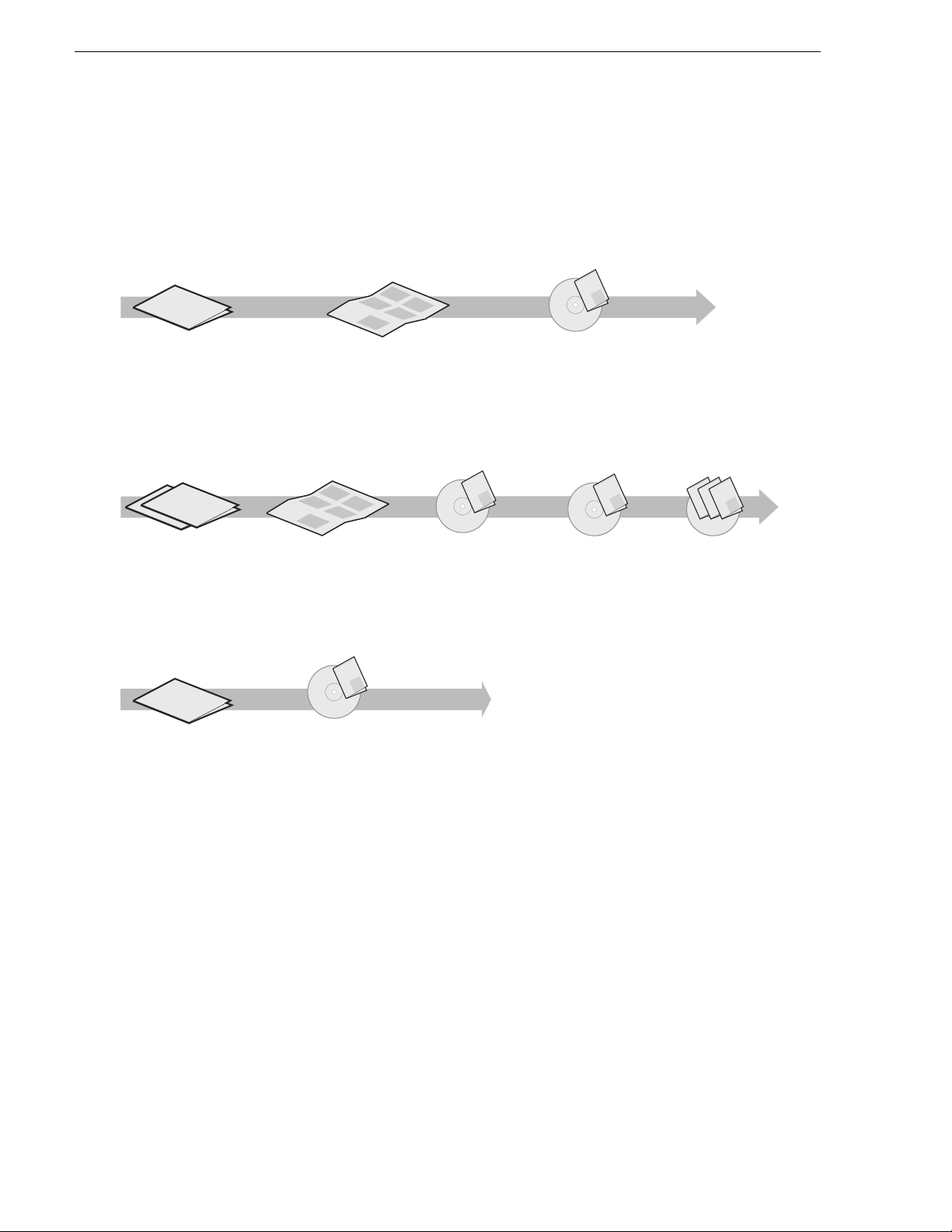
The following illustration shows the recommended order in which to reference the
documentation.
Path for the installer of K2 Media Client models with internal storage
Valley
Grass
K2 Manual
p
u
o
r
G
r
e
r
y
s
S
e
e
e
s
S
i
P
r
e
l
X
e
l
i
P
s
S
r
a
X
f
e
e
o
i
P
V
s
s
S
f
r
X
e
o
s
e
y
i
P
r
s
S
l
f
a
X
e
e
y
i
o
s
S
i
l
P
r
m
f
e
i
X
a
y
o
G
i
P
m
F
l
X
a
f
i
y
F
o
m
l
f
a
i
o
y
F
m
l
a
y
i
F
l
m
i
a
m
F
a
F
K2 Media Client
Release Notes
The latest information about the
hardware and software shipped
with the system. Packaged with
K2 Media Client.
t
r
t
ta
n
e
S
m
k
u
c
doc
Qui
ou
s
i
y
h
K2
s
ou
T
p
y
el
s
ou
h
p
l
y
e
s
h
p
l
e
h
Quick Start Guide
The essential steps for installing
the K2 Media Client. Different
models each have their own
version, packaged with the K2
K2 Media Client
System Guide*
Specifications and
instructions for
system settings.
Documentation
CD
Media Client.
Path for the installer of the K2 Storage System with connected K2 Media Clients
ley
Val
p
u
r
o
p
G
u
y
s
r
o
e
r
e
s
i
e
G
e
l
r
l
S
i
y
s
s
e
a
e
e
S
P
r
r
e
s
i
i
V
s
X
s
e
e
e
f
P
r
ll
e
S
S
i
s
r
y
o
X
s
e
i
s
a
f
e
l
e
S
a
P
P
r
e
y
o
S
i
r
i
V
s
X
X
s
s
e
P
i
l
r
m
e
f
f
P
e
e
S
X
i
r
s
a
r
y
y
S
o
o
X
G
i
i
m
s
e
F
f
e
l
l
a
P
f
a
e
y
S
o
S
i
i
P
r
y
X
o
s
P
F
i
l
r
m
m
X
e
f
l
e
X
i
f
P
r
a
a
y
S
o
i
G
i
y
m
o
X
e
F
F
l
m
f
f
l
a
S
i
P
a
y
y
o
o
F
i
m
X
F
l
l
m
f
P
a
i
i
a
y
o
X
F
m
m
F
f
l
a
a
y
o
i
F
F
l
m
i
a
m
F
a
F
K2 Media Client and
K2 Storage System**
Release Notes
The latest information
about the hardware and
software shipped with
the system.
Path for the operator
p
u
ro
G
s
y
S
e
s
i
e
S
P
e
r
l
X
i
l
e
s
P
r
S
e
a
X
f
e
i
s
o
P
V
s
r
S
f
e
X
e
o
i
s
y
s
P
r
S
l
f
e
a
X
y
e
s
i
o
i
S
l
P
e
r
m
r
f
i
X
i
a
y
e
o
G
P
m
r
F
l
X
a
f
e
i
y
F
o
m
l
f
a
i
o
y
F
m
l
a
y
i
F
l
m
i
a
m
F
a
F
K2 Media Client
Release Notes
The latest information
about the hardware and
software shipped with
the system.
t
t
ar
t
n
e
S
k
um
c
i
c
u
o
d
Q
u
o
s
2
i
u
K
s y
o
Th
p
l
u
e
s y
o
h
p
l
e
s y
h
p
l
e
h
K2 Storage System
Cabling Guide**
Diagrams for
cabling K2 Storage
System devices.
K2 Storage System
Instruction Manual*
Instructions to
install/configure K2
Storage (external),
with K2 Media Client,
K2 Media Server.
ley
Grass Val
ual
K2 Man
Documentation
CD
K2 Media Client
User Manual*
Information for using the user
interface to record, play and
manage clips and to configure
channels.
Grass
K2 Manual
Documentation
CD
K2 Media Client
System Guide*
Specifications and
instructions for
system settings.
Find the K2 Documentation CD packaged with K2 Media
*
Clients and with K2 RAID Storage devices, primary chassis.
Find the Storage Release Notes and Cabling Guide
**
packaged with K2 RAID Storage devices, primary chassis.
ley
Grass Val
K2 Manual
Documentation
CD
Other Manuals*
Including:
-
Quick Start Guide
-
User Manual
- Service Manual
- RAID manuals
ley
ley
Grass Val
Grass Val
Grass Valley
K2 Manual
K2 Manual
K2 Manual
Documentation
CD
K2 Storage System Release Notes
The release notes contain the latest information about the software shipped on your
system. The release notes include software upgrade instructions, software
specifications and r equir ements, f eatur e change s from t he previ ous rel eases , and any
known problems. Because release notes contain the latest information, they are
printed out rather than included in the Documentation CD-ROM. You can find the
release notes packaged with the primary RAID storage chassis.
K2 Storage System Cabling Guide
The cabling guides provide diagrams for storage system cabling and external
configuration, su ch as setting addre sses on RAID devices. Ther e is a cabling guid e for
Level 2 online K2 Storage Systems and a cabling guide for L evel 3 online K2 Stor age
16 K2 Storage System Instruction Manual July 3, 2007
Page 17

Systems. Each cabling guide covers both redundant and non-redundant systems.
Cabling guides do not cov er Nearl i ne K2 St ora ge Sys te ms . You can find the cabling
guide packaged with the primary RAID storage chassis.
Documentation CD-ROM
Except for the release notes, the full set of support documentation, including this
manual, is available on the Documentation CD-ROM that you receive with your K2
Storage System. You can find the Document ation CD-ROM packaged with the RAID
storage chassis.
The Documentation CD-ROM includes the following:
K2 Storage System Instruction Manual — Contains installation, configuration, and
•
maintenance procedures for shared storage options.
K2 Storage System Cabling Guide — Contains di agrams for cabling the devices of
•
the K2 Storage System.
RAID Instruction Manuals — There is an Instruc tion Ma nual for each typ e of RAID
•
storage device that can be a part of a K2 Storage System. These manuals contain
procedures for configuring and servicing the device.
K2 Media Client System Guide — Contains the product specifications and
•
step-by-step instructions for mo difying system settings. Includes instructions for
adding a K2 Media Client to the K2 Storage System.
K2 Media Client Quick Start Guides — The Quick Start Gui des provides step-by- step
•
installation inst ructions for basic installation and oper ation of the K2 Media Clien t,
including recording and playing clips.
K2 Media Client User Manual — Describes the K2 Media Client and provides
•
instructions for configuring and operating the product.
K2 Media Client Service Manual — Contains information on servicing and
•
maintenance.
On-line Help Sy st e m s
K2 Media Client Help — You can access the on-line help through the AppCenter user
interface as follows:
• In the menu bar select
Help, then choose AppCenter Help Topics from the
drop-down menu.
NetCentral Help — From the NetCentral interface access on-line help as follows:
• For general help with NetCentral manager, select
• For help sp ecific to monitoring K2 Storage System system devices, select
| Device Providers
and then select the monitored device.
Thomson Grass Valley Web Site
This public Web site contains all the latest manuals and documentation, and
additional support information. Use the following URL.
Help | NetCentral Help Topics.
Help
http://www.thomsongrassvalley.com.
July 3, 2007 K2 Storage System Instruction Manual 17
Page 18

Finding Information
Using the Dell Server documentation
This manual contains all of the inf ormation you need to install the K2 Storage S ystem,
however, a full set of Dell server documentation has been provided on the Dell
Product Documentation CD-ROM. The Dell server documentation applies to the K2
Media Server. Refer to the documents on this CD-ROM only as required by
procedures in this manual.
Information referenced on the Dell Product Documentation CD-ROM includes, but
is not limited to:
• Unpacking and rack-mounting the K2 Media Server
• Important safety and regulatory information
• K2 Media Server Status indicators, messages, and error codes
• Troubleshooting help for the K2 Media Server hardware.
!
CAUTION: Do not use the Dell Quick Instal lation Guide provided with
the Dell CD-ROM package. Thi s g u id e i ncl ude s i nst ructions for using
the OpenManage software CD-ROM to install an operating system.
The K2 Media Server comes fully configured and is ready for
installation. To begin installation, refer to one of the installation
chapters in this manual.
18 K2 Storage System Instruction Manual July 3, 2007
Page 19

Grass Valley Product Support
T o get technica l assistance, che ck on the status of a q uestion, or to report new issue, contac t
Grass Valley Product Support via e-mail, t he W eb, or by ph one or fax. Contact Grass Valley
first regarding problems with third party software on Grass Valley products, such as the
Microsoft
internet browser, an d SQL Server™.
Web Technical Support
Phone Support
®
Windows® operating system, Windows Media® player, Internet Explorer
To access support in formation on t he Web, visit the pro duct support Web p age on the
Grass Valley Web site. You can download software or fi nd sol ut ion s t o pr obl ems by
searching our Frequently Asked Questions (FAQ) database.
World Wide Web: http://www.thomsongrassvalley.com/support/
Technical Support E-mail Address: gvgtechsupport@thomson.net.
Use the following information to contact product support by phone during business
hours. Afterhours phone support is available for warranty and contract customers.
Grass Valley Product Support
®
International
(France)
International
(United States,
Canada)
Hong Kong,
Taiwan, Korea,
Macau
Australia, New
Zealand
Central, South
America
China +861 066 0159 450 Netherlands +31 (0) 35 62 38 421
Belgium +32 (0) 2 334 90 30 Northern Europe +45 45 96 88 70
Japan +81 3 5484 6868 Singapore +65 6379 1313
Malaysia +603 7805 3884 Spain +41 487 80 02
Middle East +971 4 299 64 40 UK, Ireland, Israel +44 118 923 0499
+800 80 80 20 20
+33 1 48 25 20 20
+1 800 547 8949
+1 530 478 4148
+852 2531 3058 Indian
+61 1300 721 495 Germany, Austria,
+55 11 5509 3440 Near East, Africa +33 1 48 25 20 20
Authorized Support Representative
Italy +39 02 24 13 16 01
+39 06 87 20 35 42
Belarus, Russia,
Tadzikistan,
Ukraine,
Uzbekistan
Subcontinent
Eastern Europe
+7 095 258 09 20
+33 (0) 2 334 90 30
+91 11 515 282 502
+91 11 515 282 504
+49 6150 104 444
A local authorized support represent ative may be avail able in your countr y. To locate the
support representat ive for your count ry, visit the pro duct support Web page on the Grass
Valley Web site.
July 3, 2007 K2 Storage System Instruction Manual 19
Page 20

Finding Information
20 K2 Storage System Instruction Manual July 3, 2007
Page 21

Chapter 1
Product Description
This chapter describes the K2 Storage System as follows:
• “Overview Description” on page 22
• “Key features” on page 23
July 3, 2007 K2 Storage System Instruction Manual 21
Page 22
Chapter 1 Product Description
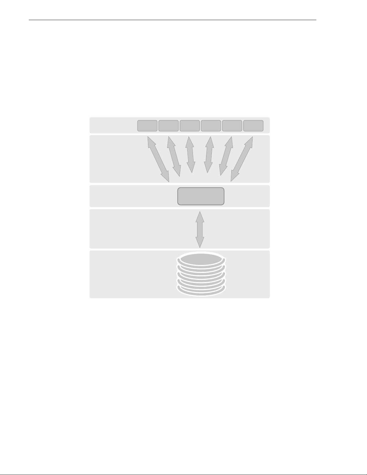
Overview Description
The K2 Storage System is Grass Valley’s shared storage solution that gives multiple
clients access t o a common pool of med ia. Clients ac cess the share d media storage vi a
a Gigabit Ethernet network and a Fibre Channel connection. Data is communicated
using the Small Computer System Interface (SCSI) data transfer interface and the
Internet SCSI (iSCSI) protocol.
iSCSI Clients
iSCSI over
Gigabit
Ethernet
iSCSI to SCSI
Bridge
SCSI over
Fibre Channel
RAID
Storage
K2 Media Server
Refer to the sections la ter in this manual for the system description of each of the
different levels of storage available, as follows:
• “Level 2 system description” on page 26
• “Level 2R system description” on page 70
• “Level 3 system description” on page 126
• “Level 3R system description” on page 174
Refer to the K2 Media Client System Guide for diagrams and explanations of the
media file system and the media database.
The Grass Valley K2 Me dia Client can also sup port a direct Fibr e Channel connection
to the storage. Contact your Grass Valley representative for more information.
22 K2 Storage System Instruction Manual July 3, 2007
Page 23

Key features
The key features of the K2 Stora ge System are as follows:
• iSCSI storage access protocol
• Gigabit Ethernet connectivity
• RAID 1, 3, 5, and 6 storage
• FTP transfers
• Standard IT networked storage configurations to fit a wide variety of size and
performance requirements.
• Scaling from 100 to < 1000MB/s
• Redundancy and fault recovery with no single point of failure
• Tuned and optimized file system for reliable and robus t transactio n of media files
• Best in class storage management for high th rou ghput , de terministic performanc e
with load balancing
Key features
July 3, 2007 K2 Storage System Instruction Manual 23
Page 24

Chapter 1 Product Description
24 K2 Storage System Instruction Manual July 3, 2007
Page 25

Chapter 2
Installing the Level 2 Storage System
Use this chapter to install the K2 Level 2 (L2) storage system.
This chapter includes th e following topics:
• “Level 2 system description” on page 26
• “Preparing Level 2 devices” on page 27
• “K2 configuration and NetCentral” on page 44
• “Networking for Level 2” on page 45
• “Configuring the Level 2 storage system” on page 49
• “Adding K2 Storage System clients” on page 63
• “Basic operations for Level 2 storage” on page 63
Work through these topics sequentially to install the storage system.
July 3, 2007 K2 Storage System Instruction Manual 25
Page 26
Chapter 2 Installing the Level 2 Storage System
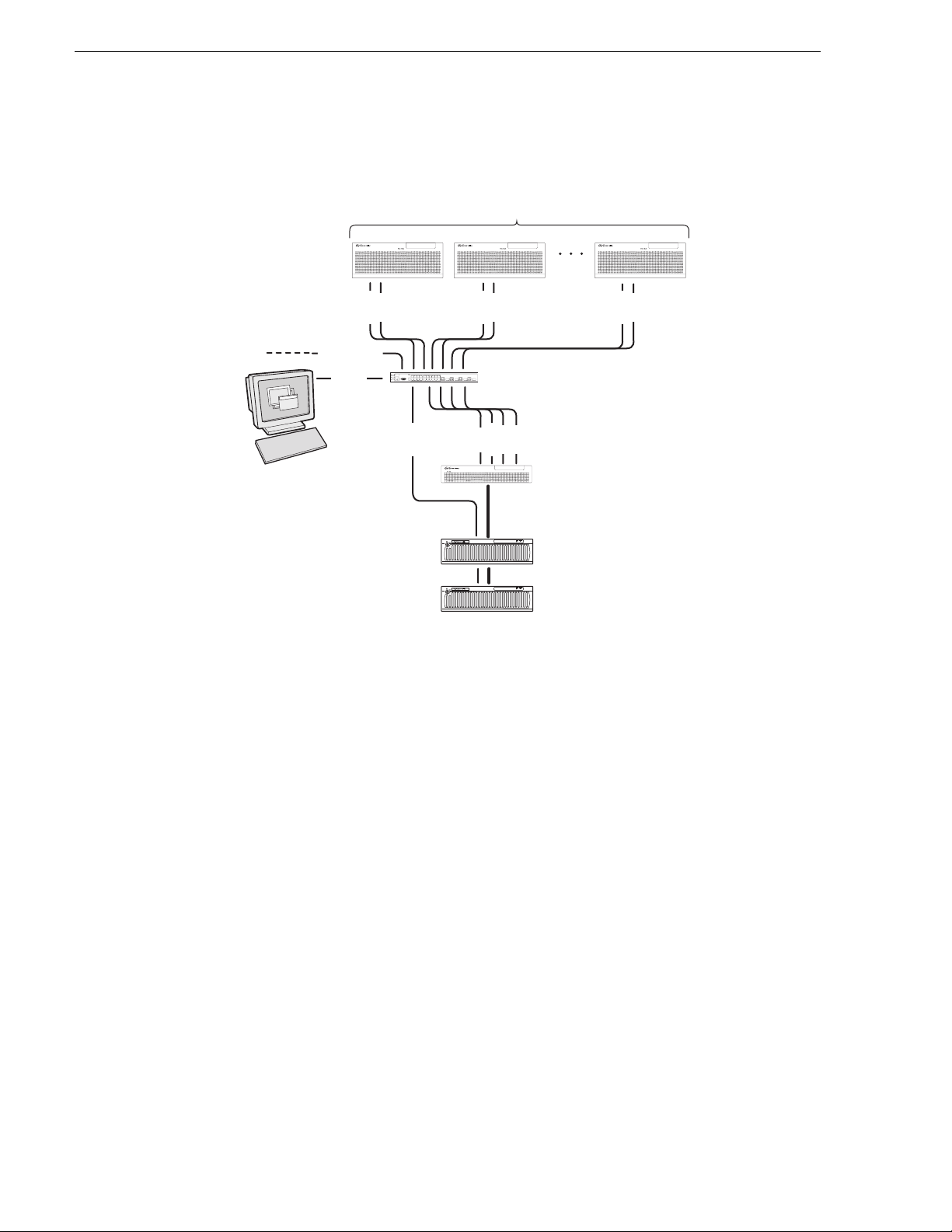
Level 2 system description
! ! !
Multiple iSCSI clients
FTP/streaming
Control
Control point PC
Control
Media
Control
Control
Media
Gigabit Ethernet switch
Control
Media
Media
FTP
K2 Media Server
Control
Media
Fibre Channel
connection
!
RAID STORAGE
K2
SERVICE
POWER
L2 RAID chassis
!
RAID STORAGE
K2
SERVICE
POWER
L2 RAID Expansion
chassis (optional)
The Level 2 storage system has one K2 Media Server and one L2 RAID chassis. An
Expansion chassis is optional for increased storage capacity.
K2 Media Clients and other iSCSI clients, such as Aurora Edits, are connected to the
GigE switch. Each client has one GigE connection for media and one GigE
connection for control. The GigE switch is configured with V-LANs to keep the
control/FTP traffic and the media (iSCSI) traffic separate.
The K2 Media Server has two GigE con necti ons for media, one Gi gE connec tion f or
control, one GigE connecti on for FTP, and one Fibre Channel connection to the RAID
storage. The server hosts iSCSI interface cards for the GigE media connections and a
Fibre Channel card for the RAID storage connection. The iSCSI interface cards
provide a bridge betwee n GigE iSCSI and Fibre Channe l SCSI. The ser ver also hosts
software components that allow it to function in various roles, including media file
system manager, media database server, and FTP server.
The L2 RAID chassis is connected via a single Fibre Channel connection to the K2
Media Server. It is al so conn ected t o the GigE cont ro l networ k, which is re quire d fo r
SNMP (NetCen tral) monito ring.
The K2 configuration control po int PC is c onnected to the GigE control net work. The
K2 System Configuration application runs on this PC for configuring the storage
system.
FTP/streaming traffic accesses the K2 Storage System via the FTP GigE port on K2
Media Servers. FTP/streaming traffic does not go to K2 Media Clients.
26 K2 Storage System Instruction Manual July 3, 2007
Page 27

Refer to Chapter 7, Description of K2 Storage Devices for more information. Also
refer to “Design considerations for Ethernet switches” on page 388.
Preparing Level 2 de vi ce s
Use the topics in thi s sect ion to pre pare ea ch devic e so that i t is r eady to b ecome part
of the Level 2 storage system.
• “Setting up the Control Point PC” on page 27
• “Setting up the Level 2 GigE switch” on page 28
• “Setting up the K2 Media Server” on page 38
• “Setting up the L2 RAID chassis” on page 39
• “Preparing K2 Storage System clients” on page 43
Setting up the Control Point PC
To set up the K2 configuration Control Point PC, you have the following options:
• Use the Grass Valley Cont ro l Poi n t PC that com e s fr om th e fa ctory with software
pre-installed. This includes the K2 System Configuration application, remote
AppCenter, and NetCentral software. Refer to the K2 Media Client System Guide
for rack mount instructions.
Preparing Level 2 devices
• Use a PC that you own and install the required software.
For either option, you must do the following fo r the Control Point PC th at runs the K2
System Configuration application:
• Assign a control network IP address to the PC. Refer to “Networking tips” on
page 56.
• Connect the PC to the GigE control network.
To use your own PC, you must additionally do the following:
• Verify that the PC meets system requirements, then install the Control Point
software and other supporting s oftware, as s pecified in the K2 Media Client System
Guide.
• Install and license NetCentral se rver software. You can in stall this on the
NetCentral server PC, which can be the K2 configuration Control Point PC. Refer
to the NetCentral User Guide.
Also refer to “Control point PC description” on page 284.
To fix the screen resolution problem seen with NetCentral on the Grass Valley
Control Point PC, do the following:
1. Go to Display properties (right mouse selection of properties on the display area)
2. Select Settings tab
3. Select the Advanced button
4. In the General tab, s et the DPI setting to Normal size (96 D PI)
5. Restart the PC
July 3, 2007 K2 Storage System Instruction Manual 27
Page 28
Chapter 2 Installing the Level 2 Storage System
Setting up the Level 2 GigE switch
These procedures are for the HP ProCurve switch.
For iSCSI traffic, you must use the HP ProCurve switch. Both the 3400cl series and
2900 series switches are qualified for iSCSI traffic, and both types are fully
compatible and can coexist on the network.
For control and FTP/stre aming traffic, it is allowed to use a different brand of switch,
such as a Cisco Catalyst switch, if required by your site. If you are using a non-HP
switch, apply the information in the following procedures accordingly. Refer to the
documentation you received with the switch as necessary.
Also refer to “Design considerations for Ethernet switches” on page 388.
• Use CAT5e or CAT6 cables. The maximum cable length is 50 meters for CAT5e
and 100 meters for CAT6.
• Assign an IP address and logon to the switch. Refer to “Configuring the GigE
switch via serial connection” on page 29.
• Set up VLANs on the switch. Refe r to “Conf ig uri ng t he GigE switch via the Web
interface” on page 32.
• Install the switch in its permanent location.
• Provide power to the switch.
• Connect cables as follows:
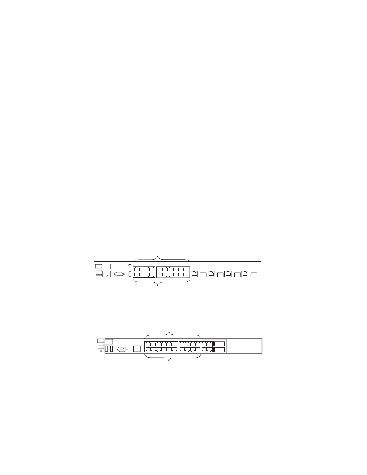
3400cl series switch
2900 series switch
Media Ports
1 - 19 odd
Control Ports
2 - 20 even
Media Ports
1 - 19 odd
Control Ports
2 - 20 even
To the media port s make one iSCSI connect ion from each K2 Media Client or other
iSCSI client, and two iSCSI connections from the K2 Media Server.
To the control ports make a conne ction fro m each K2 Media Client or other iSCSI
client, from the RAID storage chassis, and from the control point PC. Also make
the FTP network connection and the control network connection from the K2
Media Server.
28 K2 Storage System Instruction Manual July 3, 2007
Page 29

Refer to “Level 2 system description” on page 26 for a diagram of the complete
system.
Refer to cabling proced ures later in this chapter for the GigE connection s at each of
the devices of the K2 Storage System.
Also refer to “K2 Ethernet switch description” on page 285 and “Design
considerations for Ethernet switches” on page 388.
Configuring the GigE switch via serial connection
The following proced ure is for t he HP ProCurve s witch and appli es to both the 3400cl
series and 2900 series switches.
Use a direct console connection to the switch, start a console session, and access the
Switch Setu p screen to set the IP address.
1. Configure the PC terminal emulator on the control point PC or another PC as a
DEC VT-100 (ANSI) termi nal o r use a VT-1 00 ter mina l, and confi gure eithe r one
to operate with these settings:
• Baud rate 115200
Setting up the Level 2 GigE switch
• 8 data bits, 1 stop bit, no parity, and flow control set to Xon/Xoff
• Also disable (un check) the “ Use Functi on, Arrow, a nd Ctrl Ke ys for Win dows”
option
2. Connect the PC to the switch’ s Console Port usi ng the console ca ble included wi th
the switch. (If your PC or t erminal has a 25-pi n serial connect or, first attach a 9-pin
to 25-pin straight-through adapter at one end of the console cable.)
3. Turn on the PC’s power and start the PC terminal program.
4. Press
Enter two or three times a nd you will se e the copyrig ht page and th e message
“Press any key t o c ont inue”. Press a key, an d you will then see t he switch console
command (CLI) prompt.
NOTE: If you press Enter too man y times and get past the log in, enter the
command EN to get into the command line.
5. Type the following, then press
Enter:
menu
If prompted to save the current configuration, answer no (press the n key) to
proceed. The main menu opens.
6. On the main menu, choose
7. Select
IP Configuration, then press Enter.
Switch Configuration, then press Enter.
8. Press the right-arrow key to choose
Edit, then press Enter. Tab to fields and enter
information as follows:
a. Change
b. Tab to the
July 3, 2007 K2 Storage System Instruction Manual 29
Gateway to be the default router.
IP Config (DHCP/Bootp) field and use the Space bar to select the
Page 30

Chapter 2 Installing the Level 2 Storage System
Manual option.
c. Tab to the
IP Address field and enter the switch’s control network IP address.
Refer to “Networking tips” on page 56.
d. Tab to the
9. Press
Enter, then right-arrow to Save. Press Enter and revert to previous menu.
10.Select
11.From the main menu, chose
Subnet Mask field and enter the subnet mask used for your network.
Return to Main Menu and press Enter.
Console Passwords and press Enter. The Set Password
Menu opens.
12.Chose
Set Manager Password and press Enter.
13.When prompted for the password, type a password of up to 16 ASCII characters
with no spaces and press
Enter. The password can be one that is used on ot her K2
devices, such as “adminK2” or “K2admin”, or it can be your site's administrator
password.
14.When prompted to ent er th e password again, retype th e password and press
15.Select
16.From the main menu, tab to
Return to Main Menu and press Enter.
Command Line (CLI) and press Enter. The command
Enter.
prompt appears.
17.Type the following, then press
Enter:
configure
You are now in configuration mode.
18.Configure an administrator username. The username can be one that is used on
other K2 devices, such as “administrator” or “K2admin”, or it can be your site's
administrator userna me. For example, to set the user name t o “ad ministrator” type
the following, then pre ss
Enter:
password manager user-name administrator
19.When prompted, enter and re-enter the pass word.
20.Set spanning tree to RSTP. Type the following, then press
Enter:
spanning-tree force-version rstp-operation
This configures spa nning tr ee, but i t does no t turn s panning t ree on. You must tur n
spanning tree on using the switch’s Web interface, as explained in the next
procedure “Configuring the GigE switch via the Web interface”.
21.Decide your SNMP community name as explained in the follo wing opt ions, then
proceed with the next step:
• If you decide to use a unique SNMP community name (not “public”), add the
community and set it s RW permissions . For example, if the community na me is
“K2”, type the following, then press
Enter:
snmp-server community K2 unrestricted
• If you decide to use the default SNMP community “public” for NetCentral
monitoring, which already has RW permissions set as required by NetCentral,
proceed to the next step.
30 K2 Storage System Instruction Manual July 3, 2007
Page 31

Setting up the Level 2 GigE switch
22.Enter the SNMP community and IP address of the NetCentral server PC. For
example, if the IP a ddress is “192.168.40.11” and the community is “pu bli c”, you
type the following, then press
snmp-server host public 192.168.40.11
Enter:
23.Enable Authentication traps. Type the following, then press
Enter:
snmp-server enable traps authentication
This allows NetCentral to test the switch to verify that it can send its SNMP trap
messages to NetCentral.
24.Type the following, then press
Enter:
menu
When prompted, save the configuration by pressing the y key. The main menu
opens.
25.If you need a trunk for ISLs to gang switches together, use the following steps.
These steps illustrat e trunki ng the la st two ports fo r the two 10 Gig IS Ls, whic h is
the recommended configura tion f or ISLs on all multi- switc h K2 Stora ge Syste ms.
Refer to “Design considerations for Ethernet switches” on page 388 and consult
with your Grass Valley representative if your requirements deviate from the
recommended policy:
a. At the main menu, select
b. Choose selection
Port/Trunk Settings and press Enter.
c. Press the right-arrow key to choose
Switch Configuration and press Enter.
Edit, then press Enter.
d. Down arrow until at the bottom of the list of ports.
e. Right-arrow over to the Group column.
f. Use the Space bar and set the bottom 10 Gig port to
Trk1. Depending on the
switch model, this is port 26 or port A3.
g. Set the next port up also to
h. Press
26.Select
Enter, then right-arrow to Save. Press Enter and revert to previous menu.
Return to Main Menu and press Enter.
27.From the main menu, tab to
Trk1.
Command Line (CLI) and press Enter. The command
prompt appears.
28.Check the version of firmware currently installed on the switch. Type the
following, then press
Enter:
show flash
Information is displayed similar to the following example:
HP_iSCSI_switch1# show flash
Image Size(Bytes) Date Version
----- ---------- -------- -------
Primary Image : 3287779 03/15/05 M.08.66
Secondary Image : 3287779 03/15/05 M.08.66
July 3, 2007 K2 Storage System Instruction Manual 31
Page 32

Chapter 2 Installing the Level 2 Storage System
Boot Rom Version: I.08.07
Current Boot : Primary
29.Check the Primary Image Version and refer to your K2 Storage System Releas e
Notes for information about current ly supported versions. The n proceed as f ollows:
•If K2 Storage System Releas e Not es ins truct you to change the fi rm war e o n the
switch, do so before continuing. Refer to the documentation you received with
the switch for instructions to change the firmware. Then continue with the next
procedure “Configuring the GigE switch via the Web interface”.
•If K2 Storage System Release Notes confirm that the version on the switch is a
currently supported version, continue with the next procedure.
30.Type the following, then press
Enter:
menu
The main menu opens.
31.From the main menu, choose
Reboot Switch and press Enter. When prompted
“Continue Reboot…?', answer yes (pres s the y key) to p roceed. The switch restarts.
32.You can now use the switch ’s web bro wser interface for fur the r co nfi gur at ion, as
instructed in the next procedure.
33.Close the PC terminal program and disconnect the console cable.
Continue with the next procedure “Configuring the GigE switch via the Web
interface”.
Configuring the GigE switch via the Web interface
The following proced ure is for the HP ProCurve switch and ap plies to bot h the 3400cl
series and 2900 series switches.
1. From the control point PC or another PC, make su re that you have a direct Ethernet
cable connection to the switch, with no switches, routers, proxies, or other
networking devices in between.
2. On the PC, open Intern et Expl orer and typ e the s witch’ s IP a ddr ess in the Addr ess
field, as in the following example.
http://192.168.100.61
This should be the name or IP address as currently configured on the switch.
3. Press
Enter to open the switch’s configuration application.
NOTE: The configuration application for the HP ProCurve switch requires Java.
You can also access the switch’s configuration application from the K2 System
Configuration applicat ion.
4. In the switch’s configuration application, choose
Features
32 K2 Storage System Instruction Manual July 3, 2007
.
Configuration, then Device
Page 33

Setting up the Level 2 GigE switch
5. Set Spanning Tree to On and click Apply Changes. If prompted, log in with the
switch’s administrator username and password.
6. Click
Port Configuration.
7. If you do not need trunks, such as on a one- swi tc h syst em, sk ip t o the next ste p in
this procedure. If you need trunks, such as on a two-switch system with ISLs, do
the followin g:
a. Select (Ctrl + Click) the trunked ports. Typically the trunked ports are at the
bottom of the list. In the configuration for 10 Gig ISLs, two of the ports at the
bottom of the list are labeled Trk1.
July 3, 2007 K2 Storage System Instruction Manual 33
Page 34

Chapter 2 Installing the Level 2 Storage System
b. Click Modify Selected Ports.
This setting
varies depending
on switch model.
Set as instructed
in text.
c. For the trunked ports, set Port Enabled to
Yes. On some switch models, the 10
Gig ISL ports are disabled by default, so make sure you enable them. Leave
Mode as default of
Auto.
d. Set Flow Control as follows:
- For the 3400cl series switch, set to
- For the 2900 series switch, set to
Disable.
Enable.
If you have both 3400c l series and 2900 serie s on your network, havi ng different
Flow Control settings (disable for 3400cl, enable for 2900) does not cause
problems.
e. Click
Apply Settings.
8. On the Port Configuration page, do one of the following:
• If you do not have trunks, select all ports.
• If you have trunks, select the remaining ports (the ports not trunked).
34 K2 Storage System Instruction Manual July 3, 2007
Page 35

9. Click Modify Selected Ports.
Setting up the Level 2 GigE switch
This setting varies
depending on
switch model. Set
as instructed in
text.
10.Make su re Port Enabled is set to
Yes, leave Mode as default of Auto.
11.Set Flow Control as follows:
- For the 3400cl series switch, set to
- For the 2900 series switch, set to
Disable.
Enable.
If you have both 3400cl series and 2900 series on your network, having different
Flow Control settings (disable for 3400cl, enable for 2900) does not cause
problems.
12.Click
Apply Settings. Wait until settings are applied and the Web interface
becomes active.
13.Choose
VLAN Configuration. If prompted, log in with the switch’s administrator
username and password.
July 3, 2007 K2 Storage System Instruction Manual 35
Page 36

Chapter 2 Installing the Level 2 Storage System
14.Create a new Media (iSCSI) VLAN as follows:
a. Click
Add/Remove VLANs.
b. In the VL AN Name field enter Media.
c. In the VLAN ID field enter 60.
d. Click
e. Click
Add VLAN.
Main Screen to return to VLAN Configuration.
15.Configure the Media VLAN as follows:
a. In the Media VLAN row, click
Modify.
36 K2 Storage System Instruction Manual July 3, 2007
Page 37

Setting up the Level 2 GigE switch
b. Select all the odd numbered ports. (Tip: Use Ctrl + Click.)
c. In the Mode drop-down list, select
Untagged, then click Apply. This removes the
odd ports from the default (Control) VLAN.
If you have a trunk, do not configure it as “Tagged”. Media VLAN traffic
(iSCSI) does not go over the trunk.
16.Click the
VLAN Configuration tab.
17.If you have a trunk, configure the default (Control) VLAN as follows:
a. In the DEFAULT_VLAN row, click
Modify.
b. In the Current Mode list box, scroll down and select the trunk.
c. In the Mode drop-down list, sele ct
Tagged, then click Apply. This allows default
VLAN traffic (non-iSCSI) to go over the trunk.
18.Click the
VLAN Configuration tab.
July 3, 2007 K2 Storage System Instruction Manual 37
Page 38

Chapter 2 Installing the Level 2 Storage System
19.If you have a trunk , ver if y t hat for t he default VLAN the trunk is d isp layed in the
Tagged Ports column.
20.If you have two switches, repeat this procedure for the other switch.
21.Close the switch configurati on appl ication.
Setting up the K2 Media Server
Both the Dell PowerEdge 2850 and the Dell PowerEdge 2950 are qualified as
platforms for the K2 Media Server. This section provides information on both
platforms.
Do the following to prepare a K2 Media Server:
• Install the server in its permanent location. Refer to the rack mount instructions that
you received with the server’s product bundle.
• Provide power to the server.
• Connect cables as follows:
Dell 2850 PowerEdge server
3
2
1
iSCSI interface
ports
(GigE media)
Fibre Channel
Dell 2950 PowerEdge server
PCI 1
Serial port
VGA monitor
Power
Keyboard/Mouse
(USB)
PCI 2
PCI 3
GigE
port 1
(control)
Serial port
GigE
port 2
(FTP)
VGA monitor
Power supply
GigE
port 2
(FTP)
GigE
port 1
(control)
Power supply
Keyboard/Mouse
(USB)
Fibre Channel
iSCSI
interface
ports
(GigE
Media)
Connect the two iSCSI interface ports to media ports on the GigE switch.
Connect the motherboard GigE port 1 and GigE port 2 to control ports on the
GigE switch.
Connect one of the Fibre Channel ports to the RAID storage device.
• Assign a control network IP address to GigE port 1. Use standard Windows
procedures. Refer to “Networking tips” on page 56.
• Change the hostname. Use standard Windows procedures.
38 K2 Storage System Instruction Manual July 3, 2007
Page 39

• Configure SNMP propertie s so the tr ap destina tion points to the NetCent ral serv er
PC. Use standard Windows proce dures. If you are not using the SNMP communit y
name “public”, configure the community name and set permissions to RW. Also
make sure that the Authenticatio n trap is enabled.
Also refer to “K2 Media Server description” on page 287.
Setting up the L2 RAID chassis
Do the foll owing to pr epare the L 2 RAID storage devices:
• Install the chassis in its permanent location. Refer to the L2 RAID Instruction
Manual for rack mount instructions.
• “Assign Fibre Channel address ID” on page 40.
• “Connect the L2 RAID chassis” on page 40
• “Assign chassis address on Expansion chassis” on page 41.
• “Power on the L2 RAID chassis” on page 43
In addition, you will configure network settings, SNMP settings, and bind LUNs.
These tasks are part of the K2 System Configuration application and Storage Utility
procedures later in this chapter. The process of binding LUNs can take a significant
amount of time—as much as eight hours—so you might want to put priority on the
tasks necessary to star t the LUN binding process , then catch up with other tas ks while
the LUNs are binding.
Setting up the L2 RAID chassis
Also refer to “K2 Level 2 RAID storage description” on page 290.
July 3, 2007 K2 Storage System Instruction Manual 39
Page 40

Chapter 2 Installing the Level 2 Storage System
Assign Fibre Channel address ID
Every RAID controller must have a unique Fibre Channel address ID that identifies
the controller on the Fibre Channel fa bric. To set the Fi bre Channel addr ess ID on the
L2 RAID, refer to the following diagram:
Set a Fibre Channel address on the
L2 RAID controller.
Connect the L2 RAID chassis
Connect Fibre Channel cabling.
Maximum of 1 Expansion Chassis
L2 RAID
Expansion
Chassis
(if installed)
0
Address ID = 1
1
To media server
L2 RAID
Chassis
Connect Ethernet and dia gnostic cabling as shown i n the following diagram. Be awar e
of the following cabling requirements of the Level 2 storage devices:
• Each L2 RAID chassis has a singl e connection to th e Ethernet fabr ic through its
LAN card.
• The Expansion Adapter on the L2 RAID Expansion cha ssis requires a dia gnostic
40 K2 Storage System Instruction Manual July 3, 2007
Page 41

cable, which must be connected.
Install Ethernet and diagnostic cabling as shown.
Diagnostic cable
L2 RAID
Expansion
Chassis
(if installed)
Setting up the L2 RAID chassis
L2 RAID Chassis
Ethernet cable
Assign chassis address on Expansion chassis
Every chassis must have a chassis address. The Level two RAID chassis address is
fixed at 0, so no configuration is required. However, if you have a L2 RAID
Expansion chassis you must set its chassis address to 1 as shown in the following
illustratio n. Also veri fy that the diagnostic ID switches are in the posi tion shown.
Connect to a
control port
Ethernet Switch
July 3, 2007 K2 Storage System Instruction Manual 41
Page 42

Chapter 2 Installing the Level 2 Storage System
Set the chassis address to 1 on both
L2 RAID Expansion adapters.
1
4 3 2 1ON
Chassis
Address = 1
ID = "0"
Do not swap Expansion ch ass is or otherwi se re config ure st orag e. If you conne ct a
L2 RAID Expansion chassis to the wrong controller such that the Expansion
chassis contains disk modul es that were bound usin g a different contr oller you will
lose your media file system.
42 K2 Storage System Instruction Manual July 3, 2007
Page 43

Power on the L2 RAID chassis
Connect power cords, and turn on power as shown.
You must power-up any RAID Expansion chassis
prior to, or at the same time as the RAID Controller
chassis. Verify power-up as shown.
Preparing K2 Storage System clients
Ready
LED
Ready
LED
Power Cords
(115V/230V)
Power -up Verification
Ready LEDs on RAID controllers are steady ON.
Front panel Power LED is ON, Service LED is OFF
after approximately 3 minutes.
Refer to the L2 RAID Instruction Manual if there is a
problem.
Power LED
Service LED
RAID STORAGE
K2
!
SERVICE
POWER
Your preparations for L2 RAID storage are now complete.
Preparing K2 Storage System clients
Any devices that function as iSCSI clients to the K2 Storage System must be pr epared
with the following requirements:
• One or more connections to the control network.
• A static IP address for the contro l network.
• For a Level 2 or 3 (non-redundant) K2 Storage System, one connection to the
media (iSCSI) network.
Additional steps that are required for Aurora Edits include the following:
• Implemen t Aurora Edit security fe atures.
• Install SNFS software and K2 software.
July 3, 2007 K2 Storage System Instruction Manual 43
Page 44

Chapter 2 Installing the Level 2 Storage System
For more informati on, refer to the Aurora Edit Ins tallation and Confi guration Guide.
For more information refer to the K2 Media Client System Guide.
K2 configuration and NetCentral
Before you begin using the K2 System Configuration application to configure the
storage system, you should set up the NetCentral system according to the following
requirements:
NetCentral installed — NetCentral server software must be installed on a
•
NetCentral server PC. This can be the K2 configuration Control Point PC or
another PC that has network communication with the K2 Storage System control
network.
Device providers instal led — A device pr ovider must be ins talled on the NetCentral
•
server PC for each type of de vice in t he K2 Storage System. For a Lev el 2 stor age
system, the following device providers must be installed:
• Control point PC device provider — This is the Windows monitoring device
provider.
• K2 Media Server device provider
• HP Gigabit Switch device provider or Cisco Gigabit Switch device provider
• K2 Media Client device provider, if any K2 Media Clients are accessing the
Level 2 storage system.
• Device provider for iSCSI clients, if any iSCSI clients such as Aurora Edits are
accessing the Level 2 storage system.
• K2 Level 2/Level 3 RAID storage device provider. This device provider
supports both Level 2 and Level 3 RAID devices.
Grass Valley PC Monitor ing softwar e installed — This software must be installed on
•
the K2 configuration Co ntrol Point P C. It incl udes Grass Vall ey SNMP agents and
other WMI based components to perform process monitoring. This provides the
informati on for some of the SNMP trap message s that must be sent to NetCentral.
Control Point PC monitored by NetCentral — The K2 configuration C ontrol Poin t
•
PC should be added to the NetCentral system and fully monitored by NetCentral.
This means t hat its SNMP trap destination is set to send SNMP trap s to the
NetCentral server PC. Whether the Control Point PC and the NetCentral server PC
are the same PC or are different P Cs, you should still add the Control Point PC to
NetCentral.
Refer to the NetCentral User Guide to set up the NetCentral system. After installing
a device provider, you can find additio nal documentation about moni to ri ng that type
of device on the NetCentral Help menu.
44 K2 Storage System Instruction Manual July 3, 2007
Page 45

Networking for Level 2
Use the topics in this se ction to configur e the Gigabit Ether net (GigE) network f or the
Level 2 storage system.
• “Networking requirements” on page 45
• “Networking tips” on page 46
• “Setting up host tables” on page 47
• “Testing the control network” on page 48
Networking requirements
Required networking s trategies for a Level 2 K2 Storage System (a non-r edundant K2
Storage System) are as follows:
• Three networks:
• Media network — Exclusively for iSCSI traffic.
• Streaming/FTP network — For media transfers and FTP traffic.
• Control network — For all other non-streaming, non-iSCSI traffic.
Networking for Level 2
• Networks must be on separate subnets.
• The Media (iSCSI) network traffic is kept separate from any other traffic. This
separation is provided by dedicated Gigabit ports, cables, and by a dedicated
VLAN on the HP GigE switch or by separate switches.
• K2 Media Servers have a dedicated FTP port. If the server takes the role of FTP
server, make a dedicated FTP connection to the FTP port.
• While control and FTP traffi c is each on its own s ubnet, it is not re quired th at each
type of traffic has its own VLAN on GigE switches. For example, you make both
FTP and control connecti ons to the “control” ports (DEFAULT_ VLAN) on the HP
GigE switch.
• Static IP addresses are required for the media netw ork on K2 Storage System iSCSI
devices. This includes K2 Media Servers, generic iSCSI clients (such as Aurora
Edits), and K2 Media Clients.
• Machine names (host names) assigned to each K2 device.
• Host tables (hosts file s) pr ovide name resolution on each K2 Media Client , iSCSI
client, and K2 Media Server.
• IP addresses for FTP/streaming ports must have name resolution such that
hostnames are appended with the “_he0” suffix. You can use host tables (as in
“Setting up host tables” on page 47) or another mechanism to provide the name
resolution. This directs the streaming traffic to the correct port. Refer to the K2
Media Client System Guide for a complete explanation.
• K2 Media Servers must be on the streaming network, as they provide the FTP
interface for s har ed s tor age streaming traffi c. External (shared ) s tor age K2 M edi a
Clients do not need to be on the streaming network because they do not send or
receive streaming traffic.
July 3, 2007 K2 Storage System Instruction Manual 45
Page 46

Chapter 2 Installing the Level 2 Storage System
• On the external storage K2 Media Cl ient, the two con trol GigE ports are configured
as a team. The control team shares a single IP add res s. Do not attempt to un-team
the control ports. On the Level 2 K2 Storage System, only one control port is
connected, as control team redundancy is not supported.
• On the external stor age K2 Media Client, t he two media (iSCSI ) GigE ports are not
teamed. On the Level 2 K2 Storage System, only one media port is connected, as
iSCSI redundancy is not supported.
Also refer to “About networks and FTP” o n page 318 and “Design considerations for
Ethernet switches” on page 388.
Use the following procedures as necessary to implement your networking strategies.
NOTE: It is recommended that you c onfigure Media network (iSCSI) IP add resses
and Streaming network IP addresses using the K2 System Configuration
application, rather than doing so on the local machine using standard Windows
procedures.
Networking tips
• Before beginning network configuration, determine the IP addresses and names
needed for the machines in your K2 system. Work with the network administrator
at your facility to have those IP addresses and names available for your use.
• Establish a consistent convention for machine names and IP addresses. It is
recommended that you embed a root name or other unique identifier for this
particular K2 Storage System in the computer name. Also, a common convention
for IP addresses is to use a numerical pattern or sequence in the IP addresses to
indicate device-types and/or ports, as in the following example:
NOTE: This example assumes a subnet mask of 255.255.255.0
Example of Level 2 names and IP addresses
Computer
name
root_server _1 K2 Media
root_raid_1 RAID — 192.168.100.51 — —
root_gige_1 GigE switch — 192.168.100.61 — —
root_cppc_1 Control point PC— 192.168.100.81 — —
root_client_1 iSCSI client — 192.168.100.111 192.168.99.111 —
root_client_2 iSCSI client — 192.168.100.121 192.168.99.121
root_client_3 iSCSI client — 192.168.100.131 192.168.99.131
root_client_4 iSCSI client — 192.168.100.141 192.168.99.141
a.
This IP address must resolve to hostname root_server_1_he0
Device type Streaming network
Server
addresses
192.168.101.11
a
Control network
addresses
192.168.100.11 192.168.99.11 —
Media network
addresses
192.168.99.12 —
Comments
46 K2 Storage System Instruction Manual July 3, 2007
Page 47

Setting up host tables
The hosts file is used by the control network and the streaming/FTP network to
determine the IP address of devices on the network when only a the device name
(hostname) is given. The steps that fol lo w descr ibe how to edit the hosts file located
at C:\Windows\system32\drivers\etc\hosts on Windows XP and Windows 2003
Server operating syst em compute rs. If you i nclude th e names and addr esses of all the
devices on the netw ork, then you can cop y the same f ile onto al l the ot her K2 devi ces
instead of editing the hosts file on each K2 device.
For FTP transfers on a K2 Storage Sys tem, transfers go to/from K2 Medi a Servers that
have the role of FTP server. No trans fe rs go di re ctly to/from the external stor age K2
Media Clients that are on the K2 Storage System. So in the hosts file, you must add
the “he_0” extension to a K2 Media Server hostname and associate that hostname
with the K2 Media Server’s FTP/streaming network IP address.
Refer to the K2 Media Client System Guide for more information.
To edit the hosts file manually:
1. Open the following file using Notepad or some other text editing application:
C:\Windows\system32\drivers\etc\hosts
Setting up host tables
2. Enter all IP addresses wi th machine names. The te xt format is simple. Firs t type the
Ethernet IP address, t hen use the TAB key or Space bar to insert a few spaces. Th en
type the machine name.
Here is an example:
192.168.100.11 root_server_1
192.168.101.11 root_server_1_he0
192.168.100.51 root_raid_1
192.168.100.61 root_gige_1
3. Save the file and exit the text editor.
4. Copy the new hosts fi le onto al l the oth er mach ines. Thi s is easi er than editin g the
file on each machine.
Host table tips
• If transferring to or from a Profile XP or Open SAN system via UIM, the hosts file
must also follow UIM naming conventions for those systems. Refer to the UIM
Instruction Manual.
• Do not enter media (iSCSI) network IP addresses in the host table, as hostname
resolution is not required for the media network.
• Use the following tip with care. While it can solve a problem, it also introduces a
name resolution “anomaly” that might be confusing if not considered in future
troubleshooting act iv it ies.
For each SAN (external storage) K2 Media Client, add the “_he0” suffix to the
hostname but then associate that hostnam e with the K2 Media Server’s FTP/
streaming network IP ad dre ss, not the K2 Media Client’s IP address. Aliasing K2
Media Client hostnames in this way would not be required if the transfer source/
destinatio n was always correctly specified as the K2 Media Server. However, a
July 3, 2007 K2 Storage System Instruction Manual 47
Page 48

Chapter 2 Installing the Level 2 Storage System
common mistake is to attempt a transfer in which the source/destination is
incorrectl y specified as the K2 Media Client. The host file aliasing corrects this
mistake and redir ec ts to the K2 Media Server, whic h i s t he correct transf er sou rce /
destination.
An example of a hosts file entry with this type of aliasing is as follows:
192.168.101.11 server_1_he0 client_1_he0 client_2_he0
Testing the control network
To test the control network use the ping command as follows :
1. On the control point PC, click
2. Type cmd and click
OK. The command prompt window opens.
Start | Run. The Run dialog box opens.
3. Type ping, then a spa ce, then the name of one of your K2 St orage System devices ,
such as the Gigabit Ethernet switch, as in the following example:
ping root_gige_1
4. Press
Enter.
The ping command should return the IP address of the device, as in the following
example:
Pinging root_gige_1.mycorp.com [192.168.100.61] with
32 bytes of data:
Reply from 192.168.100.61: bytes=32 time=10ms TTL=127
Reply from 192.168.100.61: bytes=32 time<10ms TTL=127
Reply from 192.168.100.61: bytes=32 time<10ms TTL=127
Reply from 192.168.100.61: bytes=32 time<10ms TTL=127
This verifies that the name of the dev ice is bein g correctly resolved to the IP
address, which indicates that on the Control Point PC the hos t table entry is corr ect.
5. Ping the other K2 Storage System devices to which you have assigned control
network IP addresses.
6. Go to each Windows device in the K2 Storage System and repeat this procedure.
This verifies that network communication is correct to and from all devices.
48 K2 Storage System Instruction Manual July 3, 2007
Page 49

Configuring the Level 2 storage system
Configuring the Level 2 storage system
Use the topics in this section to do the initial configuration of the Level 2 storage
system.
• “Prerequisites for initial configuration” on page 49
• “Defining a new K2 Storage System” on page 50
• “Configuring the server - Part 1” on page 52
• “Configuring RAID” on page 54
• “Creating a new file system” on page 59
• “Configuring the server - Part 2” on page 60
Prerequisites for in it ial c onf ig ura t io n
Before beginning your init ial c onfigu ratio n, mak e sure the de vices of th e K2 Stor age
System meet the following prerequisites. Refer to sections earlier in this manual for
detailed information. Also refer to Chapter 7, “Description of K2 Storage Devices”.
Devices Prerequisite for Level 2 configuration
Control point PC E thernet cable connected
Control Point software installed
Control network IP address assigned
Network communication over the control network with all other K2
devices
Power on
Ethernet switch Ethernet cables connected
Control network IP address assigned
VLANs set up
Power on
K2 Media Server Ethernet cables con nected
Fibre Channel cable connected
Software installed, as from the factory, including QuickTime 7
Control network IP address assigned
Power on
L2 RAID chassis Fibre Channel address ID assigned to RAID controller(s)
Fibre Channel cable(s) connected
Ethernet cable(s) connected
Power on
L2 RAID Expansion
chassis
(optional)
Chassis address assigned (for Fibre Channel)
Fibre channel cable(s) connected
Power on
July 3, 2007 K2 Storage System Instruction Manual 49
Page 50

Chapter 2 Installing the Level 2 Storage System
Defining a new K2 Storage System
Define a Level 2 K2 Storage System as follows:
1. On the control point PC, open the K2 System Configuration application. A login
dialog box opens.
2. Log in to the K2 System Configuration application with the Windows
administrator account. By defau lt this as foll ows:
• Username: administrator
• Password: adminK2
Refer to “Setting up application securit y” on page 322 for more information about
administrator accounts and logging in to applications.
3. Click
New K2 System. The New K2 System wizard opens.
50 K2 Storage System Instruction Manual July 3, 2007
Page 51

Defining a new K2 Storage System
4. Follow the on-scree n text to define yo ur Leve l 2 K2 Storage Syst em, a s desc ribed
in the follow ing table.
On this page… Do this…
Page 1
Create a name for your Level 2 K2 Storage System and type it in the
Name box.
Select Level 2 .
The Server redundancy option is unchecked and disabled.
Next
Click
Page 2
Move clients into the Number of Devices box as appropriate for your
system.
You cannot change the number of K2 Media Servers or Ethernet
Switches, as these are pre-configured based on the level you selected in
the previous page.
Next.
Click
July 3, 2007 K2 Storage System Instruction Manual 51
Page 52

Chapter 2 Installing the Level 2 Storage System
On this page… Do this…
Page 3
Review the information on this page and verify that you have correctly
defined your K2 S to r ag e Sys t e m.
For a Level 2 storage system you should have the f ollowing:
Click
• One Gigabit Ethernet switch
•One K2 Media Server
• The number and type of clients appropri ate for your system.
Finish. The Define New K2 Storage System wizard closes.
Your K2 Storage System appears in the tree view of the K2 System Configuration
application.
5. Continue with the next procedure.
Configuring the server - Part 1
1. In the K2 System Configuration application tree view, select [PrimaryK2Server].
2. Click the
Follow the on-screen text to configure the K2 Media Server for a Level 2 K2
Configure button. The Configure K2 Server wizard opens.
52 K2 Storage System Instruction Manual July 3, 2007
Page 53

Storage System, as described in the following table:
On this page… Do this…
Define server roles
Enter the name or IP address for the K2 Media Server, as currently
configured on the machin e.
For Level 2, leave all roles selected.
Next
Click
Software Configuration
Configuring the server - Part 1
This page checks for the
software required to support
the roles you selected on the
previous page.
Software required on the
Level 2 K2 Media Server is
as follows:
•SQL Server
•K2 Server
• File System Server
•File System Client
•SNMP Services
•QuickTime
If software with Yes in the Required column reports as Not Inst alled, you
must first install it on the K2 Media Server before continuing. Refer to
Chapter 9, Managing K2 software. After installing the software, click
Check Software. When all required software reports as Installed, click
Next.
July 3, 2007 K2 Storage System Instruction Manual 53
Page 54

Chapter 2 Installing the Level 2 Storage System
On this page… Do this…
Network Configuration
This page displays the
control network Ethe rnet
port, and allows you to
configure the FTP/
Streaming netwo r k Ethe r net
port.
NOTE: This page
does not configure
the iSCSI interface
(media network)
ports.
The top port is the port over which the K2 System Configuration
application is communicating wi t h t he K2 Med ia Server. If correctly
configured, it is already ass ig ned the control network IP address, as
displayed on this page.
Select the other port and cl ick
box opens. Enter the FTP/Streaming IP address and the subnet mask and
click Apply.
Click
File System Server
Configuration
Modify. A network configuration dialog
Next.
Click Launch Storag e Manager. Storage Utility opens.
3. Continue with the next procedure to use Storage Utility to configure the storage
and file system.
Leave the Configure K2 Server wizard open while you are using Storage Utility.
When you are done with Storage Utility, you continue with the wizard.
Configuring RAID
Use Storage Utility to complete the configuration of the L2 RAID chassis, as
explained in the following topics:
• “Configuring RAID network and SNMP settings”
54 K2 Storage System Instruction Manual July 3, 2007
Page 55

• “Binding disk modules”
Refer to “Prerequisites for initia l configura tion” on page49 to confirm that the RAID
storage is ready for configuration.
Configuring RAID network and SNMP settings
Use the Storage Utility to configure the following settings for the Level 2 RAID
chassis:
•IP address
• Subnet mask
• Gateway Address
• SNMP trap destinations
For Level 2 RAID, network and SNMP settin gs are set and st ored on the RAID LAN
card. Therefore the co mbine d RAID stor age dev ices, i ncluding t he one o r tw o RAID
controllers and the optional Expansion chassis, is a single entity on the control
network. In addition, the RAID storage device i s configured b y default for the SNMP
community name “public”. If your site’s policies require using a different SNMP
community name, contact your Grass Valley representative.
Configuring RAID
To configure these settings, do the following:
1. Launch Storage Utility from the K2 System Configuration application as in the
previous procedure . If the RAID chassis has two contr ollers, you will confi gure the
network settings o n the con troller connecte d to K2 Media Ser ver you a re curr ently
configuring.
2. As prompted, wait while Storage Utility gathers system information, then Storage
Utility opens.
3. In Storage Utility tree view, expand the node for the L2 RAID, right-click the icon
for a L2 RAID controller, and select
Configuration | Network Properties. The
Controller Network Settings dialog box opens.
July 3, 2007 K2 Storage System Instruction Manual 55
Page 56

Chapter 2 Installing the Level 2 Storage System
4. Enter the control network IP address and other network settings.
5. You want SNMP trap messages go to the NetCentral server PC, so for SNMP
Configuration enter the IP address of th e NetCentral serv er PC. You can also enter
IP addresses for other SNMP managers to which you want to send SNMP trap
messages.
6. Click
OK to save settings and close.
7. In Storage Utilit y cli ck
disk modules”.
Binding disk modules
Use the following procedur e to bind disk module s as require d for the Level 2 stor age
system.
NOTE: Binding destroys all user data on t he disks.
1. In the Storage Utility main window, identify bound LUNs and unbound disks by
their placement in the hierarchy of the tree view. In the following illustration, disk
numbers are represented by “XX”. Refer to “Identifying disks” on pa ge 377 for an
explanation of how disks are actually numbered in Storage Utility.
View | Refresh. Continue wi th th e n ext proce dure “Binding
56 K2 Storage System Instruction Manual July 3, 2007
Page 57

Configuring RAID
2. To bind unbound disks for media storage, do the following:
a. Right-click the
Unbound node for a controller, then select Bind LUNs in the
context menu.
The Bind LUN dialog box opens showing all unbound disks for the controller
listed in the Available D isk list.
July 3, 2007 K2 Storage System Instruction Manual 57
Page 58

Chapter 2 Installing the Level 2 Storage System
NOTE: Leave Full Bind selected. Do not uncheck it.
b. In the
LUN TYPE drop down box, select RAID 3.
c. In the Available Disks box, select five contiguous disk s at the top o f the list.
(TIP: Use ‘shift-click’ or ‘control-click’ to select disks.)
d. Click the add (arrow) button to add disks to the Selected Disks list.
NOTE: As an aid in identifying a disk module’s physical location, select it in the
Selected Disks l ist, t hen cl ick
e. Click
OK to close the Binding LUN dialog box and begin the binding process.
Identify Disks. This causes th e dis k driv e light t o f lash.
The Progress Report dialog box opens, showing the status of the binding
process.
f. Close the Progress Report and repeat these steps for other unbound disks. If
specified by your system design, you can bind some disks as Hot Spares, as
explained in “Binding Hot Spare drives” on page 381. When you are done, if
you did not bind any extra Hot Spares, you should have the following results:
For Level two storage you should have three RAID 3 LUNs of five disks each
on a RAID storage device. If you have the optional Expansion chassis, you
would have an additional three RAID 3 LUNs of five disks each.
NOTE: Controllers can take several hours to bind a LUN. Make sure you initiate
multiple simultaneous binding processes to reduce the overall time.
g. Upon 100% completion, click
Close in Progress Report window.
NOTE: Do not proceed until all LUNs are finished binding.
3. Restar t the K2 Media Server.
NOTE: Make sure start up processes on the K2 Media Server are complete before
proceeding.
4. Continue with the next procedure “Creating a new file system”.
58 K2 Storage System Instruction Manual July 3, 2007
Page 59

Creating a new file system
1. In Stor age Utility, click Tools | Make New File System. The Setting dialog box
opens.
2. For the Real Time Input/Output (RTIO) rate, enter the value specified by your
system design. If you do not know this value, contact your Grass Valley
representative.
Creating a new file system
3. If the K2 Storage System is to be accessed by only K2 Media Cl ients you can leave
Windows Security unchecked. If accessed by Aurora Edits, refer to the Aurora Edit
Installation and Configuration Guide for instructions.
4. Click
OK. The Configuration File dialog box opens.
July 3, 2007 K2 Storage System Instruction Manual 59
Page 60

Chapter 2 Installing the Level 2 Storage System
The configuration f ile for t he media file s ystem is dis played. You can verify me dia
file system parameters by viewing th is file. Do no t edit this file. Click
A “…Please wait…” message box displays progress and a “…succeeded…”
message confirms the process is complete.
5. A message informs you that you must restart the K2 Media Server, however the
restart at the end o f the Configur e K2 Server wizard su ffices, so yo u do not need to
restart now.
6. Close the Storage Utility.
NOTE: Do not attempt to sta rt K2 Media Cl ients or otherwise bring the K2 Storage
System onli ne until instructed to do so later in th is chapter.
7. Continue with the next procedure.
Configuring the server - Part 2
1. Return to the Configur e K2 S erver page from which you l aunched Storage Utilit y
and proceed as described in the following table:
Accept.
60 K2 Storage System Instruction Manual July 3, 2007
Page 61

On this page… Do this…
File System Server
Configuration
This page checks on the
configuration of the K2
Media Server in one of its
main roles as a file system
server. The K2 Media Server
also functions as a file
system client, which is also
checked from this page.
Check. When the wizard reports that the configuration is correct,
Click
Next.
click
If you get a “The V: will not be available until this device is rebooted…”
message, you can safely continue with this procedure and follow the
instructions related to this message later in the procedure.
Configuring the server - Part 2
July 3, 2007 K2 Storage System Instruction Manual 61
Page 62

Chapter 2 Installing the Level 2 Storage System
On this page… Do this…
iSCSI Bridge Server
Configuration
This page manages the
components that bridge
between iSCSI (the GigE
media network) and the
Fibre Channel connection to
the RAID storage. You
configure network set tings
on the iSCSI adapters and
the page validates that the
Fibre Channel adapter is in
place and that the media
LUNs are visible as iSCSI
targets.
Select an iSCSI adapter and click
dialog box opens. Enter the media network IP address and the subnet
mask and click Apply. Do the same for the other iSCSI adapter.
Click
Modify. A network configuration
Check. The Validation Report opens.
Database Server
Configuration
Confirm that the iSCSI configuration is successful. Close the Validation
Report and then click Next.
You do not need to enter or configure anything on this page.
Next.
Click
62 K2 Storage System Instruction Manual July 3, 2007
Page 63

On this page… Do this…
FTP Server Configura tion
Do not modify these settings. Leave at default values of Max FTP
streams = 4 and FTP Data Socket Timeout = 60. Only qualified Grass
Valley personnel should specify other values, as these settings are
intended for use only with custom systems designed by Grass Valley.
Click Next
Completing the
Configuration Wizard
Click Finish. The wizard closes. The K2 Media Server restarts. Wait
until all startup processes have completed before continuin g. If you are
not sure if startup is complete, wait 10 minutes.
Adding K2 Storage System clients
Your configurations for the Level 2 K2 Storage System are complete.
Adding K2 Storage System clients
You can add now clients, such as K2 Media Clients or Aurora Edits , to the K2 Storage
System and configure them using the K2 System Configuration application.
• For Aurora Edits, refer to the Aurora Edit Installation and Configur ation Guide for
instructions.
• For K2 Media Clients, re fer to K2 Media Client System Guide for instructions.
Basic operations for Level 2 storage
Use the following procedures as you work on your Level 2 storage system:
• “Level 2 system power-off procedure”
• “Level 2 system power-on procedure”
For other procedures refer to “Administering and maintaining the K2 Storage
System” on page 321.
Level 2 system power-off procedure
Use the following sequence to power-off the Level 2 storage system.
1. Power-off all K2 Media clients or other iSCSI clients.
2. Shut down the K2 Media Server.
July 3, 2007 K2 Storage System Instruction Manual 63
Page 64

Chapter 2 Installing the Level 2 Storage System
3. Power-off the primary RAID controller chassis. If expansion chassis are
connected, make sure the power-off of the controller chassis is prior to or
simultane ous with the power-of f of its connected expansion chassis. Wait
approximately 30 seconds for the disk drives to spin down before proceeding.
4. Power-off all Ethernet switches.
5. Power-off the control point PC and/or the NetCentral server PC, if necessary.
64 K2 Storage System Instruction Manual July 3, 2007
Page 65

Level 2 system power-on procedure
Power on Level 2
(iSCSI) K2 Storage
System
Does the
Yes
Power on the Expansion Chassis
prior to or simultaneous with the
primary RAID chassis
system have
RAID
expansion
chassis?
No
Level 2 system power-on procedure
Power on the
primary RAID chassis
Verify Level 2 RAID devices:
-All disk access LEDs are steady
-The controller READY LED is ON
-The controller DIR LED flashes green
-The front Power LED is ON
-The front Service LED is OFF
Elapsed time: 5 minutes
Power on the
GigE switch
Verify HP ProCurve switch.
Diagnostic self test LED Behavior is as
follows:
-Initially, all the status, LED Mode and po rt
LEDs are on for most of the duration of th e
test.
-Most of the LEDs go off and then may
come on again during phas es of the self
test. For the duration of the self test, the
Test LED stays on.
When the self test completes successfully,
the Power and Fan Status LEDs remain on,
the Fault and Test LEDs go off, and the port
LEDs on the front of the switch g o into their
normal operational mode, as follows:
-If the ports are connected to active network
devices, the LEDs behave according to the
LED Mode selected. In the default view
mode (Link), th e LEDs should be on.
-If the ports are not connected to active
network devices, the LEDs will stay off.
Power on the
control point PC
Verify control point PC.
After log on, start NetCentral.
NetCentral reports devices as
offline. As each device is
powered on, check NetCentral
to verify the device’s status
Elapsed time: 1 minute
Continue with pa ge 2 of Level 2 power- on procedure
July 3, 2007 K2 Storage System Instruction Manual 65
Page 66

Chapter 2 Installing the Level 2 Storage System
Level 2 power-on procedure page 2
Power on the K2
Media Server.
From the control point P C, at
the command prompt, ping
the K2 Media Server.
No
K2
Media Server
responds to ping?
Elapsed time:
3 minutes
Yes
Power on K2 Media Clients and
other iSCSI clients.
Begin record/play operations.
Level 2 K2 Storage System
power-on complete
66 K2 Storage System Instruction Manual July 3, 2007
Page 67

July 3, 2007 K2 Storage System Instruction Manual 67
Page 68

Chapter 2 Installing the Level 2 Storage System
68 K2 Storage System Instruction Manual July 3, 2007
Page 69

Chapter 3
Installing the Level 2R Storage System
Use this chapter to install the K2 Level 2 Redundant (L2R) storage system.
This chapter includes th e following topics:
• “Level 2R system description” on page 70
• “Preparing Level 2R devices” on page 71
• “Networking for Level 2R” on page 90
• “Configuring the Level 2R storage system” on page 95
• “Adding K2 Storage System clients” on page 115
• “Basic operations for Level 2R storage” on page 116
Work through these topics sequentially to install the storage system.
July 3, 2007 K2 Storage System Instruction Manual 69
Page 70

Chapter 3 Installing the Level 2R Storage System
Level 2R system description
Multiple iSCSI clients
! ! !
FTP/streaming
Control
Control point PC
Control A
Control B
Media B
Media A
A
Control
A
Control B
Media B
ISLs
Control
Media
FTP
Control A
Media A
B
Media
Control A
Control B
Media A
Media B
Gigabit Ethernet
switches
Control
Media
Media
FTP
K2 Media
B
Servers
Fibre Channel
connections
!
RAID STORAGE
K2
SERVICE
POWER
L2R RAID chassis
!
RAID STORAGE
K2
SERVICE
POWER
L2R RAID Expansion
chassis (optional)
The Level two redundant (Level 2R) storage system has two Gigabit Ethernet
switches connected by Inter-Switch Links (ISLs) to support a redundant Ethernet
fabric. The storage system also has redundant K2 Media Servers. The servers are
configured to have id entical roles. This prov ides redundancy for data base, file system,
iSCSI bridge, and FTP roles. One L2 RAID supports redundant Fibre Channel
connections. An Expansion chassis is optional for increased storage capacity.
K2 Media Clients have a pai r of redundant (te amed) Gigabit Ethernet p orts for control
and two Gigabit Ether net po rts ( A an d B) fo r media (iSCSI). Each port of th e cont rol
team is connected to a di ff ere nt swi tch . The A media port goes to t he A Gi gE s wit ch
and the B media port goes to the B GigE switch. The GigE switches are configured
with V-LANs to keep the control/FTP and media (iSCSI) traffic separate.
Each K2 Media Server has two GigE conne ctions for media, one GigE connection for
control, one GigE connecti on for FTP, and one Fibre Channel connection to the RAID
storage. All GigE connections on a server go to the same GigE switch. The server
hosts iSCSI interfa ce cards f or the Gi gE media conne ctions a nd a Fibre Channel car d
for the RAID storage conne ction. The iSCSI int erface cards pr ovide a bridge betwe en
GigE iSCSI and Fibre Channel SCSI. The server also hosts sof tware components that
allow it to f unction in various roles, including media file system manager, medi a
database server, and FTP server. Redundant K2 Media Servers are connected by a
serial cable which supports the heartbeat signal required for automatic system
recovery (failover) features.
70 K2 Storage System Instruction Manual July 3, 2007
Page 71

The L2 RAID chassis has redundant RAID controllers to support the Fibre Channel
connections from the K2 Media Servers. The L2 RAID chassis is also connected to
the GigE control network, which is required for SNMP (NetCentral) monitoring.
On the L2 RAID chassi s th ere a re t wo RAID 1 L UNs f or medi a fi le sy stem met adata
files and journal files. The remainder of the RAID storage is RAID 3 LUNs for media.
The K2 configuration control po int PC is co nnected to the GigE cont rol network. The
K2 System Configuration application runs on this PC for configuring the storage
system.
FTP/streaming traffic accesses the K2 Storage System via the FTP GigE port on K2
Media Servers. FTP/streaming traffic does not go to K2 Media Clients.
Refer to Chapter 7, Description of K2 Storage Devices for more information. Also
refer to “Design considerations for Ethernet switches” on page 388.
Preparing Level 2R devices
Use the topics in thi s sect ion to pre pare ea ch devic e so that i t is r eady to b ecome part
of the Level 2R storage system.
• “Setting up the Control Point PC” on page 71
Preparing Level 2R devices
• “Setting up the Level 2R redundant GigE switches” on page 72
• “Setting up the K2 Media Server” on page 83
• “Setting up the L2 RAID chassis” on page 84
• “Preparing K2 Storage System clients” on page 88
Setting up the Control Point PC
To set up the K2 configuration Control Point PC, you have the following options:
• Use the Grass Valley Cont ro l Poi n t PC that com e s fr om th e fa ctory with software
pre-installed. This includes the K2 System Configuration application, remote
AppCenter, and NetCentral software. Refer to the K2 Media Client System Guide
for rack mount instructions.
• Use a PC that you own and install the required software.
For either option, you must do the following fo r the Control Point PC th at runs the K2
System Configuration application:
• Assign a control network IP address to the PC. Refer to “Networking tips” on
page 56.
• Connect the PC to the GigE control network.
To use your own PC, you must additionally do the following:
• Verify that the PC meets system requirements, then install the Control Point
software and other supporting s oftware, as s pecified in the K2 Media Client System
Guide.
• Install and license NetCentral se rver software. You can in stall this on the
NetCentral server PC, which can be the K2 configuration Control Point PC. Refer
July 3, 2007 K2 Storage System Instruction Manual 71
Page 72

Chapter 3 Installing the Level 2R Storage System
to the NetCentral User Guide.
Also refer to “Control point PC description” on page 284.
To fix the screen resolution probl em seen with NetCentral on the Grass Valley
Control Point PC, do the following:
1. Go to Display properties (right mouse selection of properties on the display area)
2. Select Settings tab
3. Select the Advanced button
4. In the Gen eral tab, set the DPI set ting to Normal size (96 DP I)
5. Restart the PC
Setting up the Level 2R redundant GigE switches
These procedures are for the HP ProCurve switch.
For iSCSI traffic, you must use the HP ProCurve switch. Both the 3400cl series and
2900 series switches are qualified for iSCSI traffic, and both types are fully
compatible and can coexist on the network.
For control and FTP/stre aming traffic, it is allowed to use a different brand of switch,
such as a Cisco Catalyst switch, if required by your site. If you are using a non-HP
switch, apply the information in the following procedures accordingly. Refer to the
documentation you received with the switch as necessary.
Also refer to “Design considerations for Ethernet switches” on page 388.
• You need at least two swit ches, so that the “A” media (i SCSI) network and the “B”
media (iSCSI) network each have their own switch.
• Use CAT5e or CAT6 cables. The maximum cable length is 50 meters for CAT5e
and 100 meters for CAT6.
• Assign an IP address and logon to each switch. Refer to “Configuring the GigE
switch via serial connection” on page 74.
• Set up VLANs on each switch. Refer to “Configuring the GigE switch via the Web
interface” on page 77.
• Install the switches in their perman ent location.
• Provide power to the switches.
• Connect cables as follows:
72 K2 Storage System Instruction Manual July 3, 2007
Page 73

3400cl series switch
2900 series switch
To the media ports on switch A, make t he “A” media (iSCSI) netwo rk connec tion
from each K2 Media Client. Also make two media (iSCSI) connections from K2
Media Server A.
Setting up the Level 2R redundant GigE switches
Media Ports
1 - 19 odd
Control Ports
2 - 20 even
Media Ports
1 - 19 odd
Control Ports
2 - 20 even
To the media ports on s wit ch B, make the “B” media (i SCSI) net work connection
from each K2 Media Client. Also make two media (iSCSI) connections from K2
Media Server B.
To the control ports on s witch A, make one control connecti on from each K2 Media
Client or other iSCSI client, fr om the RAID storage ch assis, and from the control
point PC. Also make the FTP network connection and the control network
connection from K2 Media Server A.
To the control ports on switch B, make the second control connection from each
K2 Media Client or other iSCSI clie nt. Also make the FTP network c onnection and
the control network connection from K2 Media Server B.
If you have other iSCSI clients, such as Aurora Edits, that have just one iSCSI
connection and one contr ol connection, appro ximately half of the clie nts should be
connected to switch A an d half of the clie nts sh ould be conn ected to s witch B. In a
failover event, only the clients connected to one of the switches will remain
operational, so make connections accordingly. Connect the client’s iSCSI
connection to one of the media ports on a s witch and the clien t’s control connecti on
to one of the control ports on the same switch.
Interconnect switch A and switch B with two 10 Gig ISLs.
Refer to “Level 2R system description” on page 70 for a diagram of the complete
system.
Refer to cabling proced ures later in this chapter for the GigE connection s at each of
the devices of the K2 Storage System.
Also refer to “K2 Ethernet switch description” on page 285 and “Design
considerations for Ethernet switches” on page 388.
July 3, 2007 K2 Storage System Instruction Manual 73
Page 74

Chapter 3 Installing the Level 2R Storage System
Configuring the GigE switch via serial connection
NOTE: Make sure you check the switch firmware and up grade if necessary, as
instructed at the end of this procedure.
The following proced ure is for the HP ProCurve switch and ap plies to bot h the 3400cl
series and 2900 series switches.
For redundant systems with two switches, do the following on each switch.
Use a direct console connection to the switch, start a console session, and access the
Switch Setup screen to set the IP address.
1. Configure the PC terminal emulator on the control point PC or another PC as a
DEC VT-100 (ANSI) ter minal o r use a VT-1 00 termin al, and c onfigu re ei ther one
to operate with these settings:
• Baud rate 115200
• 8 data bits, 1 stop bit, no parity, and flow control set to Xon/Xoff
• Also disable (uncheck) the “Use Function, Arrow, and Ctrl Keys for Windows ”
option
2. Connect the PC to the swit ch’s Console Port using the consol e cable inclu ded with
the switch. (If your PC or t erminal has a 25-pi n serial connect or, first att ach a 9-pin
to 25-pin straight-through adapter at one end of the console cable.)
3. Turn on the PC’s power and start the PC terminal program.
4. Press
Enter two or three ti mes and you will se e the copy right page an d the message
“Press any key t o c ont inue”. Press a key , and you will then s ee the switch console
command (CLI) prompt.
NOTE: If you press Enter too many times and get past the log in, enter the
command EN to get into the command line.
5. Type the following, then press
Enter:
menu
If prompted to save the current configuration, answer no (press the n key) to
proceed. The main menu opens.
6. On the main menu, choose
7. Select
IP Configuration, then press Enter.
8. Press the right-arrow key to choose
Switch Configuration, then press Enter.
Edit, then press Enter. Tab to fields and enter
information as follows:
a. Change
Gateway to be the default router.
b. Tab to the
Manual option.
c. Tab to the
IP Config (DHCP/Bootp) field and use the Space bar to select the
IP Address field and enter the switch’s control network IP address.
Refer to “Networking tips” on page 56.
d. Tab to the
74 K2 Storage System Instruction Manual July 3, 2007
Subnet Mask field and enter the subnet mask used for your network.
Page 75

Setting up the Level 2R redundant GigE switches
9. Press Enter, then right-arrow to Save. Press Enter and revert to previous menu.
10.Select
11.From the main menu, chose
Return to Main Menu and press Enter.
Console Passwords and press Enter. The Set Pa ssword
Menu opens.
12.Chose
Set Manager Password and press Enter.
13.When prompted for the password, type a password of up to 16 ASCII characters
with no spaces and press
Enter. The password can be one that is us ed on ot her K2
devices, such as “adminK2” or “K2admin”, or it can be your site's administrator
password.
14.When prompted to ent er the pa ssword again, retype the pa sswor d a nd press
15.Select
16.From the main menu, tab to
Return to Main Menu and press Enter.
Command Line (CLI) and press Enter. The command
Enter.
prompt appears.
17.Type the following, then press
Enter:
configure
You are now in configuration mode.
18.Configure an administrator username. The username can be one that is used on
other K2 devices, such as “administrator” or “K2admin”, or it can be your site's
administrator username. For example, to set the username to “administrator” type
the following, then press
Enter:
password manager user-name administrator
19.When prompted, enter and re-enter the pass word.
20.Set spanning tree to RSTP. Type the following, then press
Enter:
spanning-tree force-version rstp-operation
This configures spa nning tr ee, but i t does no t turn s panning t ree on. You must turn
spanning tree on using the switch’s Web interface, as explained in the next
procedure “Configuring the GigE switch via the Web interface”.
21.Decide your SNMP community name as explained in the following options, then
proceed with the next step:
• If you decide to use a unique SNMP community name (not “public”), add the
community and set its RW permis sions. For exam ple, if the communit y name is
“K2”, type the following, then press
Enter:
snmp-server community K2 unrestricted
• If you decide to use the default SNMP community “public” for NetCentral
monitoring, which already has RW permissions set as required by NetCentral,
proceed to the next step.
22.Enter the SNMP community and IP address of the NetCentral server PC. For
example, if the IP a ddress is “192.168.40.11” and the community is “pu bli c”, you
type the following, then press
Enter:
snmp-server host public 192.168.40.11
July 3, 2007 K2 Storage System Instruction Manual 75
Page 76

Chapter 3 Installing the Level 2R Storage System
23.Enable Authentication traps. Type the following, then press Enter:
snmp-server enable traps authentication
This allows NetCentral to test the switch to verify that it can send its SNMP trap
messages to NetCentral.
24.Type the following, then press
Enter:
menu
When prompted, save the configuration by pressing the y key. The main menu
opens.
25.If you need a trunk for ISLs to gang switches together, use the following steps.
These steps illustr ate trunk ing the last two ports f or the two 10 Gig ISLs, which is
the recommended configuration for ISLs on all multi-switch K2 Storage Systems.
Refer to “Design considerations for Ethernet switches” on page 388 and consult
with your Grass Valley representative if your requirements deviate from the
recommended policy:
a. At the main menu, select
b. Choose selection
Port/Trunk Settings and press Enter.
c. Press the right-arrow key to choose
Switch Configuration and press Enter.
Edit, then press Enter.
d. Down arrow until at the bottom of the list of ports.
e. Right-arrow over to the Group column.
f. Use the Space bar and set the bottom 10 Gig port to
Trk1. Depending on the
switch model, this is port 26 or port A3.
g. Set the next port up also to
h. Press
Enter, then right-arrow to Save. Press Enter and revert to previous menu.
Trk1.
26.Select
27.From the main menu, tab to
Return to Main Menu and press Enter.
Command Line (CLI) and press Enter. The command
prompt appears.
28.Check the version of firmware currently installed on the switch. Type the
following, then press
Enter:
show flash
Information is displayed similar to the following example:
HP_iSCSI_switch1# show flash
Image Size(Bytes) Date Version
----- ---------- -------- -------
Primary Image : 3287779 03/15/05 M.08.66
Secondary Image : 3287779 03/15/05 M.08.66
Boot Rom Version: I.08.07
Current Boot : Primary
29.Check the Primary Image Version and refer to your K2 Storage System Releas e
Notes for information about current ly supported versions. The n proceed as f ollows:
76 K2 Storage System Instruction Manual July 3, 2007
Page 77

Setting up the Level 2R redundant GigE switches
•If K2 Storage System Releas e Not es instr uct you to change the fi rmwar e on the
switch, do so before continuing. Refer to the documentation you received with
the switch for instructions to change the firmware. Then continue with the next
procedure “Configuring the GigE switch via the Web interface”.
•If K2 Storage System Release Notes confirm that the version on the switch is a
currently supported version, continue with the next procedure.
30.Type the following, then press
Enter:
menu
The main menu opens.
31.From the main menu, choose
Reboot Switch and press Enter. When prompted
“Continue Reboot…?' , answer yes (pres s the y key) to pr oceed. The switch r estarts.
32.You can now use the switch ’s we b browser interface for f urt he r configuration, as
instructed in the next p rocedure.
33.Close the PC terminal program and disconnect the console cable.
34.Repeat this procedure on the other switch.
Continue with the next procedure “Configuring the GigE switch via the Web
interface”.
Configuring the GigE switch via the Web interface
The following proced ure is for t he HP ProCurve s witch and appli es to both the 3400cl
series and 2900 series switches.
For redundant systems with two switches, do the following on each switch.
1. From the control point PC or another PC, make su re that you have a dir ect Ethernet
cable connection to the switch, with no switches, routers, proxies, or other
networking devices in between.
2. On the PC, open Internet Explore r and t ype t he sw itch’s I P ad dress in the Addres s
field, as in the following example.
http://192.168.100.61
This should be the name or IP address as currently configured on the switch.
3. Press
Enter to open the switch’s configuration application.
NOTE: The configuration application for the HP ProCurve switch requires Java.
You can also access the switch’s configuration application from the K2 System
Configuration applicat ion.
4. In the switch’s configuration application, choose
Features
July 3, 2007 K2 Storage System Instruction Manual 77
.
Configuration, then Device
Page 78

Chapter 3 Installing the Level 2R Storage System
5. Set Spanning Tree to On and click Apply Changes. If prompted, log in with the
switch’s administrator username and password.
6. Click
Port Configuration.
7. If you do not need trunks, such as on a one-switch system, skip to the next ste p in
this procedure. If you need trunks, such as on a two-switch system with ISLs, do
the followin g:
a. Select (Ctrl + Click) the trunked ports. Typically the trunked ports are at the
bottom of the list. In the configuration for 10 Gig ISLs, two of the ports at the
bottom of the list are labeled Trk1.
78 K2 Storage System Instruction Manual July 3, 2007
Page 79

b. Click Modify Selected Ports.
Setting up the Level 2R redundant GigE switches
This setting
varies depending
on switch model.
Set as instructed
in text.
c. For the trunked ports, set Port Enabled to
Yes. On some switch models, the 10
Gig ISL ports are disabled by default, so make sure you enable them. Leave
Mode as default of
Auto.
d. Set Flow Control as follows:
- For the 3400cl series switch, set to
- For the 2900 series switch, set to
Disable.
Enable.
If you have both 3400cl se ries and 2900 series on your network, having d ifferent
Flow Control settings (disable for 3400cl, enable for 2900) does not cause
problems.
e. Click
Apply Settings.
8. On the Port Configuration page, do one of the following:
• If you do not have trunks, select all ports.
• If you have trunks, select the remaining ports (the ports not trunked).
July 3, 2007 K2 Storage System Instruction Manual 79
Page 80

Chapter 3 Installing the Level 2R Storage System
9. Click Modify Selected Ports.
This setting varies
depending on
switch model. Set
as instructed in
text.
10.Make su re Port Enabled is set to
Yes, leave Mode as default of Auto.
11.Set Flow Control as follows:
- For the 3400cl series switch, set to
- For the 2900 series switch, set to
Disable.
Enable.
If you have both 3400cl series and 2900 series on your network, having different
Flow Control settings (disable for 3400cl, enable for 2900) does not cause
problems.
12.Click
Apply Settings. Wait until settings are applied and the Web interface
becomes active.
13.Choose
VLAN Configuration. If prompted, log in with the switch’s administrator
username and password.
80 K2 Storage System Instruction Manual July 3, 2007
Page 81

Setting up the Level 2R redundant GigE switches
14.Create a new Media (iSCSI) VLAN as follows:
a. Click
Add/Remove VLANs.
b. In the VL AN Name field enter Media.
c. In the VLAN ID field enter 60.
d. Click
e. Click
Add VLAN.
Main Screen to return to VLAN Configuration.
15.Configure the Media VLAN as follows:
a. In the Media VLAN row, click
Modify.
July 3, 2007 K2 Storage System Instruction Manual 81
Page 82

Chapter 3 Installing the Level 2R Storage System
b. Select all the odd numbered ports. (Tip: Use Ctrl + Click.)
c. In the Mode drop-down list, select
Untagged, then click Apply. This removes the
odd ports from the default (Control) VLAN.
If you have a trunk, do not configure it as “Tagged”. Media VLAN traffic
(iSCSI) does not go over the trunk.
16.Click the
VLAN Configuration tab.
17.If you have a trunk, configure the default (Control) VLAN as follows:
a. In the DEFAULT_VLAN row, click
Modify.
b. In the Current Mode list box, scroll down and select the trunk.
c. In the Mode drop-down list, select
Tagged, then click Apply. This al lows default
VLAN traffic (non-iSCSI) to go over the trunk.
18.Click the
VLAN Configuration tab.
82 K2 Storage System Instruction Manual July 3, 2007
Page 83

19.If you have a trunk , ver if y t hat for the default VLAN the trunk i s di splayed in the
Tagged Ports column.
20.If you have two switches, repeat this procedure for the other switch.
21.Close the switch configurati on appl ication.
Setting up the K2 Media Server
Both the Dell PowerEdge 2850 and the Dell PowerEdge 2950 are qualified as
platforms for the K2 Media Server. This section provides information on both
platforms.
Do the following to prepare a K2 Media Server:
• Install the server in its permanent location. Refer to the rack mount instructions that
you received with the server’s product bundle.
• Provide power to the servers.
• Connect cables as follows:
Dell 2850 PowerEdge server
Setting up the K2 Media Server
iSCSI interface
ports
3
(GigE media)
2
Fibre Channel
1
Dell 2950 PowerEdge server
PCI 1
Serial port
VGA monitor
Power
Keyboard/Mouse
(USB)
PCI 2
PCI 3
GigE
port 1
(control)
Serial port
GigE
port 2
(FTP)
VGA monitor
Power supply
GigE
port 2
(FTP)
GigE
port 1
(control)
Power supply
Keyboard/Mouse
(USB)
Connect the two iSCSI interface ports to media ports on the GigE switch.
Connect A servers to the A GigE switch. Connect B servers to the B GigE
switch.
Connect the motherboard GigE port 1 and GigE port 2 to control ports on the
GigE switch. Connect A servers t o the A GigE swit ch. Connect B serve rs to the
B GigE switch.
Connect one of the Fibre Channel ports to the RAID storage device.
Fibre Channel
iSCSI
interface
ports
(GigE
Media)
July 3, 2007 K2 Storage System Instruction Manual 83
Page 84

Chapter 3 Installing the Level 2R Storage System
Make a direct connection between the serial ports of the two servers.
Take care to use the proper serial cable to interconnect redundant K2 Media
Servers that take the role of file system/database servers. This cable supports the
heartbeat mechanism whereby the servers monitor each other’s health. It is a 9
pin serial cable, but it is not a standard RS-232 null modem c able. The hear tbeat
cable is supplied with you r system (Grass Valley part number 174 -8137-00) and
has a pin configurati on as follows:
1 – 4
2 – 3
3 – 2
4 – 1&6
5 – 5
6 – 4
7 – 8
8 – 7
9 – No Connect
• Assign a control network IP address to GigE port 1. Use standard Windows
procedures. Refer to “Networking tips” on page 56.
• Change the hostname. Use standard Windows procedures.
• Configure SNMP propert ies so the tr ap destina tion point s to the NetCen tral serv er
PC. Use standard Windows proce dures. If you are not using the SNMP communit y
name “public”, configure the community name and set permissions to RW. Also
make sure that the Authenticatio n trap is enabled.
Also refer to “K2 Media Server description” on page 287.
Setting up the L2 RAID chassis
Do the foll owing to pr epare the L 2 RAID storage devices:
• Install the chassis in its permanent location. Refer to the L2 RAID Instruction
Manual for rack mount instructions.
• “Assign Fibre Channel address ID” on page 85.
• “Connect the L2 RAID chassis” on page 85
• “Assign chassis address on Expansion chassis” on page 86.
• “Power on the L2 RAID chassis” on page 88
In addition, you will configure network settings, SNMP settings, and bind LUNs.
These tasks are part of the K2 System Configuration application and Storage Utility
procedures later in this chapter. The process of binding LUNs can take a significant
amount of time—as much as eight hours—so you might want to put priority on the
tasks necessary to star t the LUN binding process , then catch up with other tas ks while
the LUNs are binding.
Also refer to “K2 Level 2 RAID storage description” on page 290.
84 K2 Storage System Instruction Manual July 3, 2007
Page 85

Assign Fibre Channel address ID
Every RAID controller must have a unique Fibre Channel address ID that identifies
the controller on the Fibre Channel fa bric. To set the Fib re Channel ad dress ID on the
L2 RAID, refer to the following diag ram:
Set a unique Fibre Channel address on
both L2 RAID controllers.
Setting up the L2 RAID chassis
0
Address ID = 2
Connect the L2 RAID chassis
Connect Fibre Channel cabling.
Maximum of 1 Expansion Chassis
L2 RAID
Expansion
Chassis
(if installed)
2
0
Address ID = 1
1
L2 RAID
To media
server A
To media
server B
Chassis
Connect Ethernet and d iagnostic cabling as shown in the following diagram. Be aware
of the following cabling requirements of the Level 2 storage devices:
July 3, 2007 K2 Storage System Instruction Manual 85
Page 86

Chapter 3 Installing the Level 2R Storage System
• Each L2 RAID chassis has a singl e connection to th e Ethernet fabr ic through its
LAN card.
• Each Expansion Adapter on the L2 RAID Expansion chassis requires a
diagnostic cable, which must be connected.
Install Ethernet and diagnostic cabling as shown.
Diagnostic cables
L2 RAID
Expansion
Chassis
(if installed)
L2 RAID Chassis
Ethernet cable
Assign chassis address on Expansion chassis
Every chassis must have a chassis address. The Leve l two RAID chassis ad dress is
fixed at 0, so no configuration is required. However, if you have a L2 RAID
Expansion chassis you must set its chassis address to 1 as shown in the following
illustratio n. Also veri fy that the diagnostic ID switches are in the posi tion shown.
Connect to a
control port
Ethernet Switch
86 K2 Storage System Instruction Manual July 3, 2007
Page 87

Set the chassis address to 1 on both
4321ON
L2 RAID Expansion adapters.
1
Setting up the L2 RAID chassis
Chassis
Address = 1
ID = "0"
Do not swap Expansion ch ass is or o therwi se rec onfig ure st orage. I f you c onnect a
L2 RAID Expansion chassis to the wrong controller such that the Expansion
chassis contains disk modules that were bound usin g a diffe rent contr oller you will
lose your media file system.
July 3, 2007 K2 Storage System Instruction Manual 87
Page 88

Chapter 3 Installing the Level 2R Storage System
Power on the L2 RAID chassis
Connect power cords, and turn on power as shown.
You must power-up any RAID Expansion chassis
prior to, or at the same time as the RAID Controller
chassis. Verify power-up as shown.
Ready
LED
Ready
LED
Power Cords
(115V/230V)
Power -up Verification
Ready LEDs on RAID controllers are steady ON.
Front panel Power LED is ON, Service LED is OFF
after approximately 3 minutes.
Refer to the L2 RAID Instruction Manual if there is a
problem.
Power LED
Service LED
RAID STORAGE
K2
!
SERVICE
POWER
Your preparations for L2 RAID storage are now complete.
Preparing K2 Storage System clients
Any devices that function as iS CSI clients to the K2 Storage Syst em must be prepared
with the following requirements:
• One or more connections to the control network.
• A static IP address for the contro l network.
• For a Level 2R, 3R or o ther red undant K2 St orage Sys tem, K2 Media Clients hav e
one connection t o the A media (i SCSI) network and one connec tion to th e B media
(iSCSI) network. Other iSCSI cl ients with just on e media port connect to e ither the
A or the B network.
Additional steps that are required for Aurora Edits include the following:
• Implemen t Aurora Edit security features.
88 K2 Storage System Instruction Manual July 3, 2007
Page 89

• Install SNFS software and K2 software.
For more informati on, refer to the Aurora Edit Installa tion and Confi guration Guide.
Additional steps that are required for K2 Media Clients include the following:
• If the K2 Media Client connects to the K2 Storage System with a redundant
Ethernet fabric, such as in Levels 2R and 3R, install Multi-pa th I/O softwa re.
For more information refer to the K2 Media Client System Guide.
K2 configuration and NetCentral
Before you begin using the K2 System Configuration application to configure the
storage system, you should set up the NetCentral system according to the following
requirements:
NetCentral installed — NetCentral server software must be installed on a
•
NetCentral server PC. This can be the K2 configuration Control Point PC or
another PC that has network communication with the K2 Storage System control
network.
Device providers instal led — A device pr ovider must be inst alled on the NetCentral
•
server PC for each type of device in the K2 Storage Sys tem. For a Level 2R s torage
system, the following device providers must be installed:
K2 configuration and NetCentral
• Control point PC device provider — This is the Windows monitoring device
provider.
• K2 Media Server device provider
• HP Gigabit Switch device provider or Cisco Gigabit Switch device provider
• K2 Media Client device provider, if any K2 Media Clients are accessing the
Level 2R storage system.
• Device provider for iSCSI clients, if any iSCSI clients such as Aurora Edits are
accessing the Level 2R storage system.
• K2 Level 2/Level 3 RAID storage device provider. This device provider
supports both Level 2 and Level 3 RAID devices.
Grass Valley PC Monitor ing softwar e installed — This soft ware must be instal led on
•
the K2 configuration Co ntrol Point PC. It inclu des Grass Vall ey SNMP agents and
other WMI based components to perform process monitoring. This provides the
informati on for some of the SNMP trap messages that must be sent to Ne tCentral.
Control Point PC monitored by NetCentral — The K2 configuration C ontrol Poin t
•
PC should be added to the NetCentral system and fully monitored by NetCentral.
This means t hat its SNMP t rap destination is set to send SNMP traps to the
NetCentral server PC. Whether the Control Point PC and the NetCentral server PC
are the same PC or are different PCs, you should still add the Control Point PC to
NetCentral.
Refer to the NetCentral User Guide to set up the NetCentral system. After installing
a device provider, you can find addition al documentation about moni tor i ng t hat t ype
of device on the NetCentral Help menu.
July 3, 2007 K2 Storage System Instruction Manual 89
Page 90

Chapter 3 Installing the Level 2R Storage System
Networking for Level 2R
Use the topics in this section to configure the Gigabit Ethernet (GigE) network for the
Level 2R storage system.
• “Networking requirements” on page 90
• “Networking tips” on page 91
• “Setting up host tables” on page 92
• “Testing the control network” on page 93
Networking requirements
Required networking strategies for a Level 2R (a redundant K2 Storage System) are
as follows:
• Four networks:
• Media network A — Exclusively for iSCSI traffic. For failover purposes, this
network restricts traffic between an “A” media port on a K2 Media Client and
the “A” K2 Media Server with the role of media file system/database server.
• Media network B — Exclusively for iSCSI traffic. For failover purposes, this
network restricts traffic b etween a “B” medi a port on a K2 Media Clie nt and the
“B” K2 Media Server with the role of media file system/database server.
• Streaming/FTP network — For media transfers and FTP traffic.
• Control network — For all other non-streaming, non-iSCSI traffic.
• Networks must be on separate subnets.
• The real-time iSCSI traffic of the media networks (A and B) is kept separate from
traffic that is not real-time, such as that of the streaming/FTP network and the
control network. This separation is provided by dedicated Gigabit ports, cables,
and by a dedicated VLAN on the HP GigE switch or by separate switches.
• K2 Media Servers have a dedicated FTP port. If the server takes the role of FTP
server, make a dedicated FTP connection to the FTP port.
• While control and FTP traffi c is each on its own s ubnet, it is not re quired t hat each
type of traffic has its own VLAN on GigE switches. For example, you make both
FTP and control connecti ons to the “control” ports ( DEFAULT_VLAN) on the HP
GigE switch.
• Static IP addresses are required for the media networks on K2 Storage System
iSCSI devices. This in cludes K2 Media Servers, generic iSCSI clients (such as
Aurora Edits), and K2 Media Clients.
• Machine names (host names) assigned to each K2 device.
• Host tables (hosts files) provide name resoluti on on eac h K2 Media Cli ent , iSCSI
client, and K2 Media Server.
• IP addresses for FTP/streaming ports must have name resolution such that
hostnames are appended with the “_he0” suffix. You can use host tables (as in
“Setting up host tables” on page 92) or another mechanism to provide the name
90 K2 Storage System Instruction Manual July 3, 2007
Page 91

Networking tips
resolution. This directs the streaming traffic to the correct port. Refer to the K2
Media Client System Guide for a complete explanation.
• K2 Media Servers must be on the streaming network, as they provide the FTP
interface for s har ed s tor age streaming traffi c. External (shared ) s tor age K2 M edi a
Clients do not need to be on the streaming network because they do not send or
receive streaming traffic.
• On the external storage K2 Media Cl ient, the two control GigE port s are configured
as a team. The control team shares a single IP addr ess. Do not attempt to un-team
the control ports. On the Level 2R K2 Storage System (a redundant K2 Storage
System), both control ports are connected and the control team provides
redundancy.
• On the external stor age K2 Media Client, t he two media (iSCSI ) GigE ports are not
teamed. On the Level 2R K2 Storage System (a redundant K2 Storage System),
both media ports are connected and each media port is a ssigned to a dif ferent media
(iSCSI) network, which is required for redundancy.
Also refer to “About networks and FTP” on page 318 and “Design considerations for
Ethernet switches” on page 388.
Use the following procedures as necessary to implement your networking strategies.
NOTE: It is recommended that you c onfigure Med ia network (iSCSI) I P addresses
and Streaming network IP addresses using the K2 System Configuration
application, rather than doing so on the local machine using standard Windows
procedures.
Networking tips
• Before beginning network configuration, determine the IP addresses and names
needed for the machines in your K2 system. Work with t he networ k adminis trator
at your facility to have those IP addresses and names available for your use.
• Establish a consistent convent ion for machine names and IP addresses. It is
recommended that you embed a root name or other unique identifier for this
particular K2 Storage System in the computer name. Also, a common convention
for IP addresses is to use a numerical pattern or sequence in the IP addresses to
indicate device-types and/or ports, as in the following example:
NOTE: This example assumes a subnet mask of 255.255.255.0
July 3, 2007 K2 Storage System Instruction Manual 91
Page 92

Chapter 3 Installing the Level 2R Storage System
Example of Level 2R names and IP addresses
Computer
name
root_server _1 K2 Media
root_server _2 K2 Media
root_raid_1 RAID — 192.168.100.51 — Both
root_gige_1 GigE switch — 192.168.100.61 — —
root_gige_2 GigE switch — 192.168.100.62 — —
root_cppc_1 Control point PC— 192.168.100.81 — —
root_client_1 iSCSI client — 192.168.100.111 192.168.99.111 For th e con trol
root_client_2 iSCSI client — 192.168.100.121 192.168.99.121
root_client_3 iSCSI client — 192.168.100.131 192.168.99.131
root_client_4 iSCSI client — 192.168.100.141 192.168.99.141
a.
This IP address must resolve to hostname root_server_1_he0
b.
This IP address must resolve to hostname root_server_2_he0
Device type Streaming network
addresses
192.168.101.11
Server
192.168.101.21
Server
a
b
Control network
addresses
192.168.100.11 192.168.99.11 These two
192.168.100.21 192.168.98.21
Media network
addresses
192.168.99.12
192.168.98.22
192.168.98.112
192.168.98.122
192.168.98.132
192.168.98.142
Comments
servers are a
redundant pair.
controllers
share the same
IP address.
network, one
IP address is
shared b etween
the two teamed
ports. For
media
networks,
subnet 99 is th e
“A” network
and subnet 98
is the “B”
network.
Setting up host tables
The hosts file is used by the control network and the streaming/FTP network to
determine the IP address of devices on the network when only a the device name
(hostname) is given. The steps th at fol l ow descr ib e how to edit th e hosts file located
at C:\Windows\system32\drivers\etc\hosts on Windows XP and Windows 2003
Server operating sy stem compute rs. If you i nclude th e names an d addresse s of all t he
devices on the netw ork, then you can cop y the same file ont o all th e other K2 devices
instead of editing the hosts file on each K2 device.
For FTP transfers on a K2 Storage System, transfers go to/from K2 Media Server s that
have the role of FTP server. No transfers go directly to/f ro m the external storage K2
Media Clients that are on the K2 Storage System. So in the hosts file, you must add
the “he_0” extension to a K2 Media Server hostname and associate that hostname
with the K2 Media Server’s FTP/streaming network IP address.
Refer to the K2 Media Client System Guide for more information.
To edit the hosts file manually:
92 K2 Storage System Instruction Manual July 3, 2007
Page 93

Testing the control network
1. Open the following file using Notepad or some other text editing application:
C:\Windows\system32\drivers\etc\hosts
2. Enter all IP addresses wi th machine names. The te xt format is simple. Firs t type the
Ethernet IP address, t hen use the TAB key or Space bar to insert a few spaces. Th en
type the machine name.
Here is an example:
192.168.100.11 root_server_1
192.168.101.11 root_server_1_he0
192.168.100.21 root_server_2
192.168.101.21 root_server_2_he0
192.168.100.51 root_raid_1
192.168.100.61 root_gige_1
3. Save the file and exit the text editor.
4. Copy the new hosts fi le onto al l the oth er mach ines. Thi s is easi er than editin g the
file on each machine.
Host table tips
• If transferring to or from a Profile XP or Open SAN system via UIM, the hosts file
must also follow UIM naming conventions for those systems. Refer to the UIM
Instruction Manual.
• Do not enter media (iSCSI) network IP addresses in the host table, as hostname
resolution is not required for the media network.
• Use the following tip with care. While it can solve a problem, it also introduces a
name resolution “anomaly” that might be confusing if not considered in future
troubleshooting act iv it ies.
For each SAN (external storage) K2 Media Client, add the “_he0” suffix to the
hostname but then associate that hostnam e with the K2 Media Server’s FTP/
streaming network IP ad dre ss, not the K2 Media Client’s IP address. Aliasing K2
Media Client hostnames in this way would not be required if the transfer source/
destinatio n was always correctly specified as the K2 Media Server. However, a
common mistake is to a ttempt a transfer in which the source/destination is
incorrectl y specified as the K2 Media Client. The host file aliasing corrects this
mistake and redirects to the K2 Media Server, which is the correct transfer source/
destination.
An example of a hosts file entry with this type of aliasing is as follows:
192.168.101.11 server_1_he0 client_1_he0 client_2_he0
Testing the control network
To test the control network use the ping command as follows:
1. On the control point PC, click
2. Type cmd and click
OK. The command prompt window opens.
Start | Run. The Run dialog box opens.
3. Type ping, then a spa ce, then the name of one of your K2 Sto rage System devices ,
July 3, 2007 K2 Storage System Instruction Manual 93
Page 94

Chapter 3 Installing the Level 2R Storage System
such as the Gigabit Ethernet switch, as in the following example:
ping root_gige_1
4. Press
Enter.
The ping command should return the IP address of the device, as in the following
example:
Pinging root_gige_1.mycorp.com [192.168.100.61] with
32 bytes of data:
Reply from 192.168.100.61: bytes=32 time=10ms TTL=127
Reply from 192.168.100.61: bytes=32 time<10ms TTL=127
Reply from 192.168.100.61: bytes=32 time<10ms TTL=127
Reply from 192.168.100.61: bytes=32 time<10ms TTL=127
This verifies that the name of the dev ice is bein g correctly resolved to the IP
address, which indicates that on the Control Point PC the hos t table entry is corr ect.
5. Ping the other K2 Storage System devices to which you have assigned control
network IP addresses.
6. Go to each Windows device in the K2 Storage System and repeat this procedure.
This verifies that network communication is correct to and from all devices.
94 K2 Storage System Instruction Manual July 3, 2007
Page 95

Configuring the Level 2R storage system
Configuring the Level 2R storage system
Use the topics in this section to do the initial configuration of the Level 2R storage
system.
• “Prerequisites for initial configuration” on page 95
• “Defining a new K2 Storage System” on page 96
• “Configuring the server - Part 1” on page 98
• “Configuring RAID” on page 101
• “Creating a new file system” on page 107
• “Configuring the server - Part 2” on page 108
• “Configuring the redundant server” on page 111
Prerequisites for in it ial c onf ig ura t io n
Before beginning your init ial c onfigu ratio n, mak e sure the de vices of th e K2 Stor age
System meet the following prerequisites. Refer to sections earlier in this manual for
detailed information. Also refer to Chapter 7, “Description of K2 Storage Devices”.
Devices Prerequisite for Level 2R configuration
Control point PC E thernet cable connected
Control Point software installed
Control network IP address assigned
Network communication over the control network with all other K2
devices
Power on
Ethernet switch Ethernet cables connected
Control network IP address assigned
VLANs set up
Trunks set up
Power on
K2 Media Server Ethernet cables con nected
Fibre Channel cable connected
Redundant servers connected by seria l cable
Software installed, as from the factory, including QuickTime 7
Control network IP address assigned
Power on for all servers
L2 RAID chassis Fibre Channel address ID assigned to RAID controller(s)
Fibre Channel cable(s) connected
Ethernet cable(s) connected
Power on
L2 RAID Expansion
chassis
(optional)
Chassis address assigned (for Fibre Channel)
Fibre channel cable(s) connected
Power on
July 3, 2007 K2 Storage System Instruction Manual 95
Page 96

Chapter 3 Installing the Level 2R Storage System
Defining a new K2 Storage System
Define a Le vel 2R K2 Storage System as follows:
1. On the control point PC, open the K2 System Configuration application. A login
dialog box opens.
2. Log in to the K2 System Configuration application with the Windows
administrator account. By defau lt this as foll ows:
• Username: administrator
• Password: adminK2
Refer to “Setting up application securit y” on page 322 for more information about
administrator accounts and logging in to applications.
3. Click
New K2 System. The New K2 System wizard opens.
96 K2 Storage System Instruction Manual July 3, 2007
Page 97

Defining a new K2 Storage System
4. Follow the on-scr een text to define your Level 2R K2 St orage System, as described
in the follow ing table.
On this page… Do this…
Page 1
Create a name for your Level 2R K2 Storage System and type it in the
Name box.
Select Level 2 .
Select the
Click
Server redundancy op tio n.
Next
Page 2
Move clients into the Number of Devices box as appropriate for your
system.
You cannot change the number of K2 Media Servers or Ethernet
Switches, as these are pre-configured based on the level you selected in
the previous page.
Next.
Click
July 3, 2007 K2 Storage System Instruction Manual 97
Page 98

Chapter 3 Installing the Level 2R Storage System
On this page… Do this…
Page 3
Review the information on this page and verify that you have correctly
defined your K2 S to r ag e Sys t e m.
For a Level 2R storage system you should have the following:
• Two Gigabit Ethernet switches
• Two K2 Media Servers
• The number and type of clients appropri ate for your system.
Click
Finish. The Define New K2 Storage System wizard closes.
Your K2 Storage System appears in the tree view of the K2 System Configuration
application.
5. Continue with the next procedure.
Configuring the server - Part 1
1. In the K2 System Configuration application tree view, select [PrimaryK2Server].
2. Click the
Follow the on-screen text to configure the K2 Media Server for a Level 2R K2
Configure button. The Configure K2 Server wizard opens.
98 K2 Storage System Instruction Manual July 3, 2007
Page 99

Storage System, as described in the following table:
On this page… Do this…
Define server roles
Enter the name or IP address for the K2 Media Server, as currently
configured on the machin e.
Enter the name or IP address of the Ethernet switch, as currently
configured on the switch, to which t he K2 Media Server is connected.
For Level 2 redundant, leave all roles selected.
Next
Click
Software Configuration
Configuring the server - Part 1
This page checks for the
software required to support
the roles you selected on the
previous page.
Software required on the
Level 2R K2 Media Server A
is as follows:
•SQL Server
•K2 Server
• File System Server
•File System Client
•SNMP Services
•QuickTime
If software with Yes in the Required column reports as Not Inst alled, you
must first install it on the K2 Media Server before continuing. Refer to
Chapter 9, Managing K2 software. After installing the software, click
Check Software. When all required software reports as Installed, click
Next.
July 3, 2007 K2 Storage System Instruction Manual 99
Page 100

Chapter 3 Installing the Level 2R Storage System
On this page… Do this…
Network Configuration
This page displays the
control network Ethe rnet
port, and allows you to
configure the FTP/
Streaming netwo r k Ethe r net
port.
NOTE: This page
does not configure
the iSCSI interface
(media network)
ports.
The top port is the port over which the K2 System Configuration
application is communicating wi t h t he K2 Med ia Server. If correctly
configured, it is already ass ig ned the control network IP address, as
displayed on this page.
Select the other port and cl ick
box opens. Enter the FTP/Streaming IP address and the subnet mask and
click Apply.
Click
File System Server
Configuration
Modify. A network configuration dialog
Next.
Enter the name or IP address of the redundant K2 Media Server (server
B ).
Do not yet click Next. Do not yet enter anyt hing in the File System
Server #2 box.
Launch Storage Manager. Storage Utility opens.
Click
3. Continue with the next procedure to use Storage Utility to configure the storage
and file system.
Leave the Configure K2 Server wizard open while you are using Storage Utility.
When you are done with Storage Utility, you continue with the wizard.
100 K2 Storage System Instruction Manual July 3, 2007
 Loading...