

Page 1
K2
Storage
Cabling Guide
071-8713-01
April 2010
Page 2

Affiliate with the N.V. KEMA in The Netherlands
CERTIFICATE
Certificate Number: 510040.001
The Quality System of:
Thomson Inc, and its worLdwide Grass Valley division affiliates DBA
GRASS VALLEY
Headquarters
400 Providence Mine Rd
Nevada City, CA 95959
United States
15655 SW Greystone Ct.
Beaverton, OR 97006
United States
10 Presidential Way
Suite 300
Woburn, MA 01801
United States
Kapittelweg 10
4827 HG Breda
The Nederlands
7140 Baymeadows Way
Ste 101
Jacksonville, FL 32256
United States
2300 So. Decker Lake Blvd.
Salt Lake City, UT 84119
United States
Rue du Clos Courtel
CS 31719
35517 Cesson-Sevigné Cedex
France
1 rue de l’Hautil
Z.I. des Boutries BP 150
78702 Conflans-Sainte
Honorine Cedex
France
Technopole Brest-Iroise
Site de la Pointe du Diable
CS 73808
29238 Brest Cedex 3
France
40 Rue de Bray
2 Rue des Landelles
35510 Cesson Sevigné
France
Spinnereistrasse 5
CH-5300 Turgi
Switzerland
Brunnenweg 9
D-64331 Weiterstadt
Germany
Carl-Benz-Strasse 6-8
67105 Schifferstadt
Germany
Including its implementation, meets the requirements of the standard:
ISO 9001:2008
Scope:
The design, manufacture and support of video and audio hardware and software products and
related systems
.
This Certificate is valid until: June 14, 2012
This Certificate is valid as of: June 14, 2009
Certified for the first time: June 14, 2000
H. Pierre Sallé
President
KEMA-Registered Quality
The method of operation for quality certification is defined in the KEMA General Terms
And Conditions For Quality And Environmental Management Systems Certifications.
Integral publication of this certificate is allowed.
KEMA-Registered Quality, Inc.
4377 County Line Road
Chalfont, PA 18914
Ph: (215)997-4519
Fax: (215)997-3809
CRT 001 073004
Accredited By:
ANAB
Page 3
K2
Storage
SAN and Direct-Connect
Cabling Guide
071-8713-01
April 2010
Page 4

Copyright Copyright © Grass Valley, Inc. All rights reserved. Printed in the United States of America.
Portions of software © 2000 – 2010, Microsoft Corporation. All rights reserved. This document
may not be copied in whole or in part, or otherwise reproduced except as specifically permitted
under U.S. copyright law, without the prior written consent of Grass Valley, Inc., P.O. Box
59900, Nevada City, California 95959-7900. This product may be covered by one or more U.S.
and foreign patents.
Disclaimer Product options and specifications subject to change without notice. The information in this
manual is furnished for informational use only, is subject to change without notice, and should
not be construed as a commitment by Grass Valley, Inc. Grass Valley, Inc. assumes no
responsibility or liability for any errors or inacc uracies that may appear in this publication.
U.S. Government
Restricted Rights
Legend
Trademarks and
Logos
Revision Status
Use, duplication, or disclosure by the United States Government is subject to restrictions as set
forth in subparagraph (c)(1)(ii) of the Rights in Technical Data and Computer Software clause
at DFARS 252.277-7013 or in subparagraph c(1) and (2) of the Commercial Computer
Software Restricted Rights clause at FAR 52.227-19, as applicable. Manufacturer is Grass
Valley, Inc., P.O. Box 59900, Nevada City, California 95959-7900 U.S.A.
Grass Valley, K2, Aurora, Summit, Dyno, Solo, Infinity, Turbo, Profile, Profile XP, NetCentral,
NewsBrowse, NewsEdit, NewsQ, NewsShare, Ne wsQ Pro, and Media Manager are either
registered trademarks or trademarks of Grass Valley, Inc. in the United States and/or other
countries. Grass Valley, Inc. products are covered by U.S. and foreign patents, issued and
pending. Additional information regarding Grass Valley, Inc. trademarks and other proprietary
rights may be found at www.grassvalley.com. Other trademarks and logos used in this
document are either registered trademarks or trademarks of the manufactu rers or vendors of
the associated products, such as Microsoft® Windows® operating system, Windows Media®
player, Internet Explorer® internet browser, and SQL Server™. QuickTime and the QuickTime
logo are trademarks or registered trademarks of Apple Computer, Inc., used under license
therefrom.
Rev Date Description
03 September
2009
Initial release of the K2 Storage Cabling Guide - 071-8713-00
01 April 2010 Correct NH Server GigE cabling - 071-8713-01
4 K2 Storage Cabling Guide 01 April 2010
Page 5

Contents
Chapter 1 Start with the K2 storage system diagram
About custom K2 SANs...........................................................................................7
Level 2 Basic K2 SAN.............................................................................................8
Level 2 Redundant K2 SAN....................................................................................9
Level 3 Basic K2 SAN.............................................................................................10
Level 3 Redundant K2 SAN....................................................................................11
Level 10 Basic K2 SAN...........................................................................................12
Level 10 Redundant K2 SAN ..................................................................................13
Level 20 Basic K2 SAN...........................................................................................14
Level 20 Redundant K2 SAN ..................................................................................15
Level 30 Basic K2 SAN...........................................................................................16
Level 30 Redundant K2 SAN ..................................................................................17
Level 35 Basic K2 SAN...........................................................................................18
Level 35 Redundant K2 SAN ..................................................................................19
Nearline 10 Basic K2 SAN ......................................................................................20
Nearline 10 Redundant K2 SAN..............................................................................21
K2 client with direct-connect storage.......................................................................22
Chapter 2 Cable K2 devices
Cable K2 client........................................................................................................24
K2 Media Client for basic K2 SAN......................................................................24
K2 Media Client for redundant K2 SAN..............................................................25
K2 Summit Production Client for basic K2 SAN.................................................25
K2 Summit Production Client for redundant K2 SAN .........................................26
K2 Media Client with direct-connect storage......................................................26
K2 Summit Production Client with direct-connect storage..................................27
Cable Gigabit Ethernet switch.................................................................................28
3400cl HP GigE switch for basic K2 SAN...........................................................28
3400cl HP GigE switch for redundant K2 SAN...................................................29
29xx HP GigE switch for basic K2 SAN..............................................................29
29xx HP GigE switch for redundant K2 SAN......................................................30
29xx HP GigE switch for basic nearline K2 SAN................................................30
29xx HP GigE switch for redundant nearline K2 SAN........................................31
Cable K2 Media Server...........................................................................................32
Dell 2850 for basic K2 SAN................................................................................33
Dell 2850 for redundant K2 SAN ........................................................................33
Dell 1950 GS for Level 10 basic K2 SAN...........................................................34
Dell 1950 GS for Level 10 redundant K2 SAN ...................................................34
Dell 1950 GS for Level 20 basic K2 SAN...........................................................35
Dell 1950 GS for Level 20 redundant K2 SAN ...................................................35
Dell 1950 GS for Level 35 basic K2 SAN...........................................................36
Dell 1950 GS for Level 35 redundant K2 SAN ...................................................37
Dell 2950 for basic K2 SAN................................................................................38
Dell 2950 for redundant K2 SAN ........................................................................38
Dell 2950 for Level 3 basic K2 SAN ...................................................................39
Dell 2950 for Level 3 redundant K2 SAN............................................................40
Dell 2950 LS for basic K2 SAN...........................................................................41
Dell 2950 LS for redundant K2 SAN...................................................................41
Dell R610 GS for Level 10 basic K2 SAN...........................................................42
Dell R610 GS for Level 10 redundant K2 SAN...................................................42
Dell R610 GS for Level 20 basic K2 SAN...........................................................42
Dell R610 GS for Level 20 redundant K2 SAN...................................................43
Dell R610 GS for Level 35 basic K2 SAN...........................................................43
Dell R610 GS for Level 35 redundant K2 SAN...................................................44
Dell R710 LS for basic K2 SAN..........................................................................44
01 April 2010 K2 Storage Cabling Guide 5
Page 6

Contents
Dell R710 LS for redundant K2 SAN.................................................................. 45
Cable NH1 K2 Media Server...................................................................................46
Dell 1950 NH1 for online K2 SAN...................................................................... 46
Dell 1950 NH1 for basic nearline K2 SAN..........................................................46
Dell 1950 NH1 for redundant nearline K2 SAN..................................................47
Dell R610 NH1 for online K2 SAN......................................................................47
Dell R610 NH1 for basic nearline K2 SAN......................................................... 47
Dell R610 NH1 for redundant nearline K2 SAN ................................................. 48
Cable NH1-10GE K2 Media Server ........................................................................ 49
Dell 1950 NH1-10GE for online K2 SAN............................................................ 49
Dell 1950 NH1-10GE for basic nearline K2 SAN ............................................... 49
Dell 1950 NH1-10GE for redundant nearline K2 SAN........................................ 50
Dell R610 NH1-10GE for online K2 SAN ........................................................... 50
Dell R610 NH1-10GE for basic nearline K2 SAN............................................... 50
Dell R610 NH1-10GE for redundant nearline K2 SAN.......................................51
Cable K2 RAID........................................................................................................ 52
K2 RAID for Level 2 basic K2 SAN .................................................................... 53
K2 RAID for Level 2 redundant K2 SAN............................................................. 54
K2 RAID for basic K2 SAN.................................................................................55
K2 RAID for redundant K2 SAN......................................................................... 56
K2 RAID for Level 10 basic K2 SAN .................................................................. 57
K2 RAID for Level 10 redundant K2 SAN........................................................... 58
K2 RAID for Level 20 basic K2 SAN .................................................................. 59
K2 RAID for Level 20 redundant K2 SAN........................................................... 60
K2 RAID for Level 30 basic K2 SAN .................................................................. 61
K2 RAID for Level 30 redundant K2 SAN........................................................... 62
K2 RAID for Level 35 basic K2 SAN .................................................................. 63
K2 RAID for Level 35 redundant K2 SAN........................................................... 64
K2 RAID for Nearline 10 basic K2 SAN.............................................................. 65
K2 RAID for Nearline 10 redundant K2 SAN...................................................... 66
K2 RAID for K2 client direct-connect storage..................................................... 67
Chapter 3 For more information
K2 Release Notes................................................................................................... 69
K2 Documentation CD ............................................................................................ 69
On-line Help Systems ............................................................................................. 70
NetCentral documentation ......................................................................................70
Grass Valley Web Site ............................................................................................ 70
Using the Dell Server documentation......................................................................70
Grass Valley Product Support................................................................................. 71
Web Technical Support...................................................................................... 71
Telephone Support............................................................................................. 72
Waste Electrical and Electronic Equipment Directive.........................................73
6 K2 Storage Cabling Guide 01 April 2010
Page 7

Chapter 1
Start with the K2 storage system diagram
To follow cabling instructions for your K2™ Storage Area Network (SAN) or
direct-connect storage K2 client, start with the system cabling diagram for your K2
system. Then follow the references below the system diagram to locate cabling
instructions for the individual devices of your K2 system.
Refer to the K2 Storage System Instruction Manual or the K2 SAN Installation and
Configuration Guide for more information on K2 SAN levels and devices. Refer to
the K2 System Guide for more information on direct-connect K2 client storage.
• “Level 2 Basic K2 SAN” on page 8
• “Level 2 Redundant K2 SAN” on page 9
• “Level 3 Basic K2 SAN” on page 10
• “Level 3 Redundant K2 SAN” on page 11
• “Level 10 Basic K2 SAN” on page 12
• “Level 10 Redundant K2 SAN” on page 13
• “Level 20 Basic K2 SAN” on page 14
• “Level 20 Redundant K2 SAN” on page 15
• “Level 30 Basic K2 SAN” on page 16
• “Level 30 Redundant K2 SAN” on page 17
• “Level 35 Basic K2 SAN” on page 18
• “Level 35 Redundant K2 SAN” on page 19
• “Nearline 10 Basic K2 SAN” on page 20
• “Nearline 10 Redundant K2 SAN” on page 21
About custom K2 SANs
Custom systems are those that do not fit one of the pre-defined Level 2, 3, 10, 20, 30,
35, or nearline configurations. For example, a K2 SAN with Fibre Channel attached
K2 clients is considered a custom system. Custom systems that are an extension of
Level 2 or 3 are considered to be Level 4 systems. Custom systems that are an
extension of Level 10, 20, or 30 are considered to be Level 40 systems. Only qualified
Grass Valley personnel should attempt to design, install, and configure custom
systems.
This document and the other documents in the K2 documentation set are intended for
customers with one of the pre-defined SAN levels. While much of the information
also applies to custom systems, consult your Grass Valley representative before using
procedures on a custom system.
01 April 2010 K2 Storage Cabling Guide 7
Page 8
Chapter 1 Start with the K2 storage system diagram
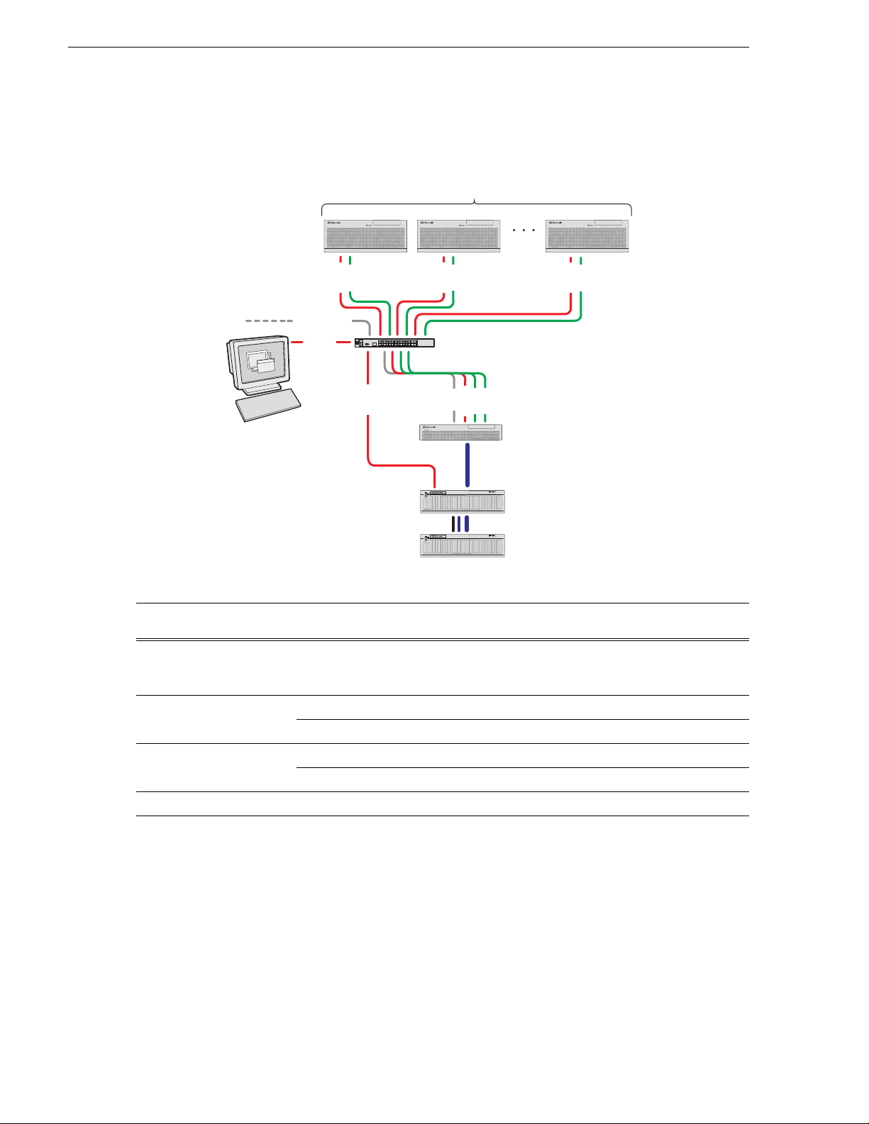
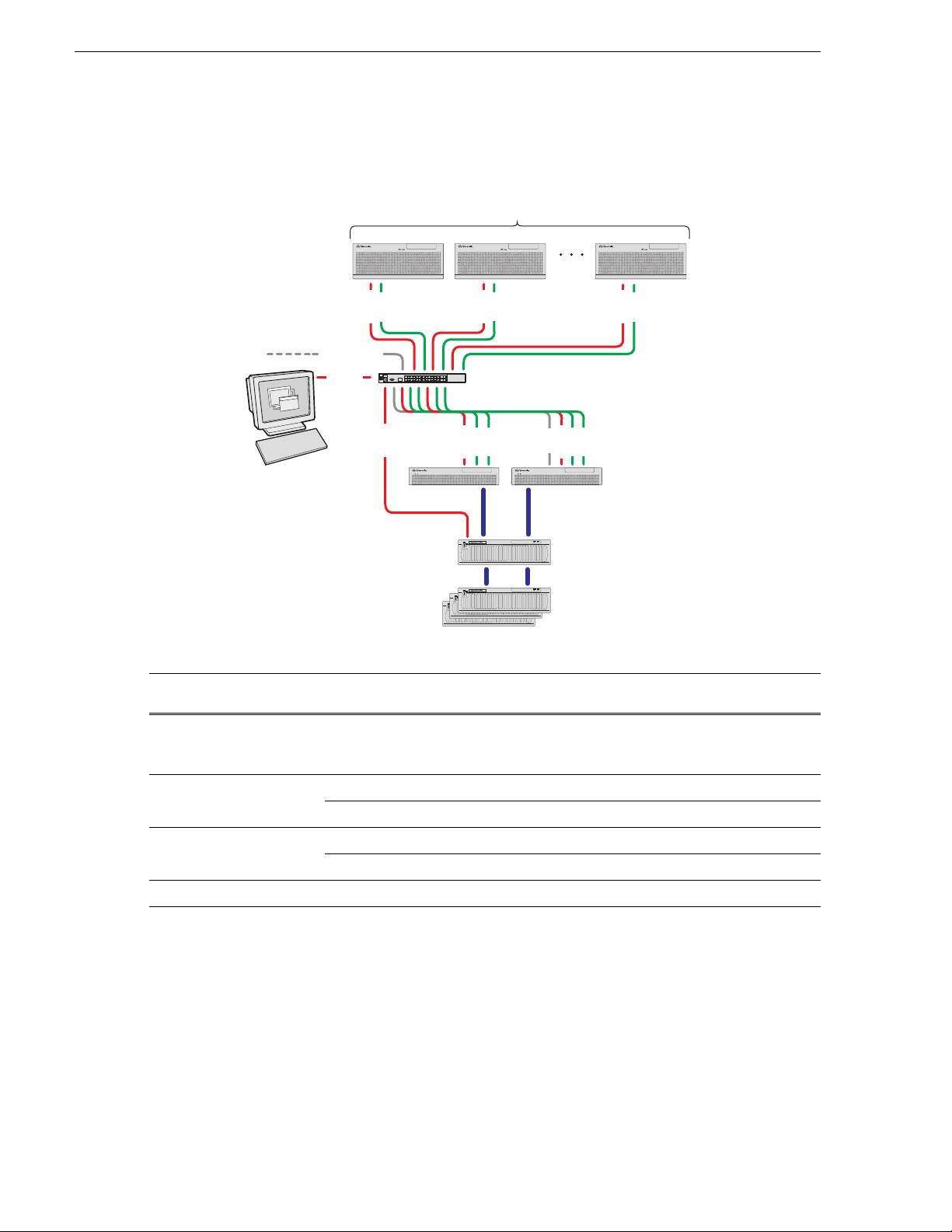
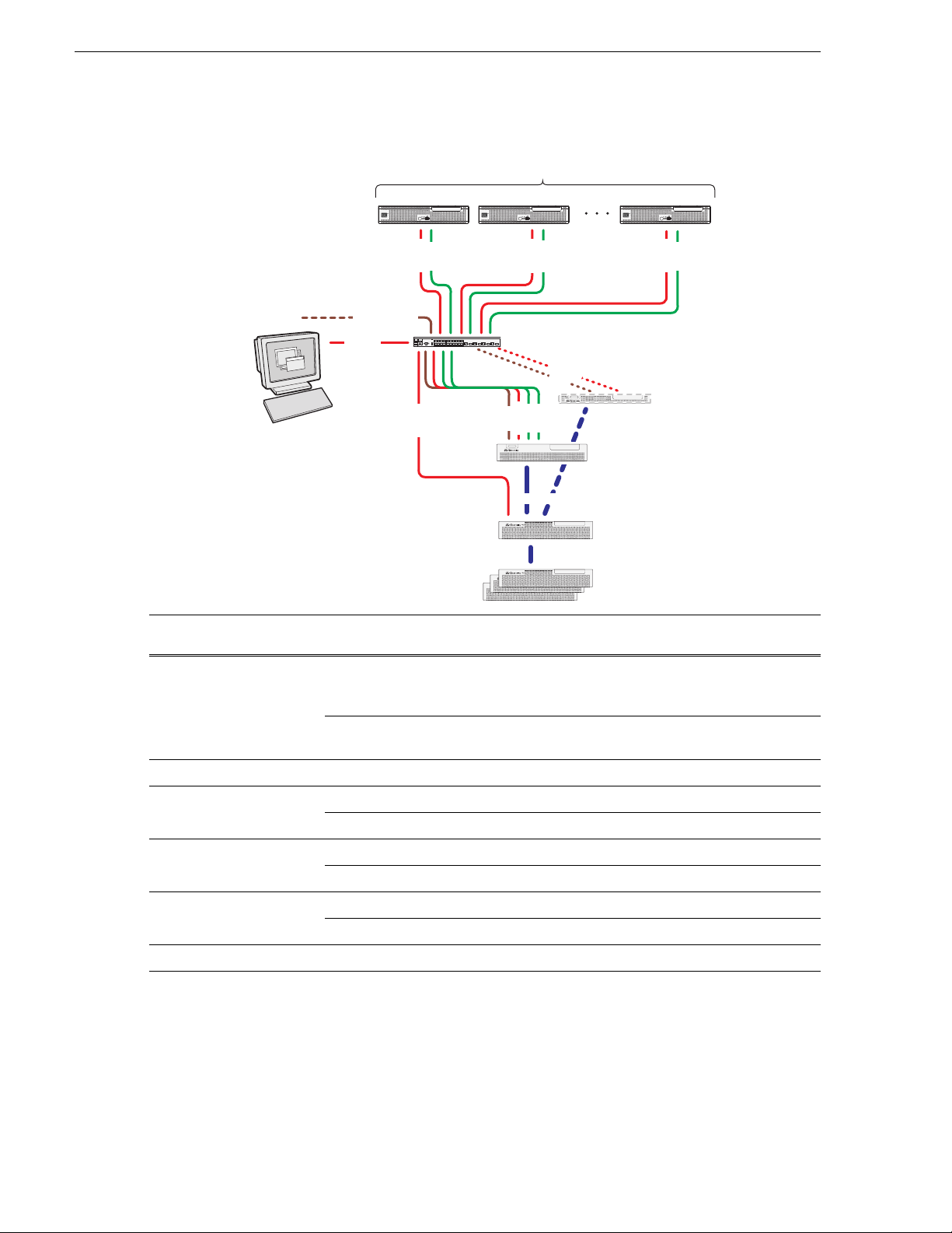
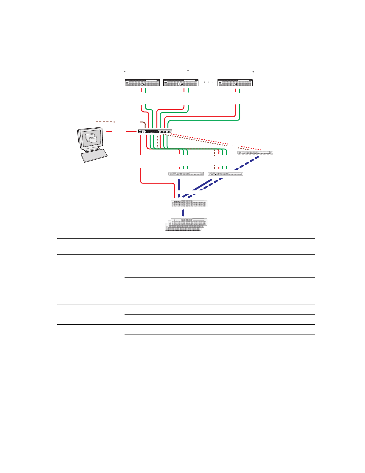
Level 2 Basic K2 SAN
! ! !
K2 Media Clients
FTP/streaming
Control
Control point PC
Control
Media
Control
Control
Media
Control
Gigabit Ethernet Switch
Control
Media
Media
FTP
K2 Media Server
Media
Fibre Channel
connection
!
RAID STORAGE
K2
SERVICE
POWER
L2 RAID Primary
Chassis
!
RAID STORAGE
K2
SERVICE
POWER
L2 RAID Expansion
Chassis (optional)
To cable this K2 SAN
device…
K2 client K2 Media Client,
Of this model or
platform…
Turn to these instructions:
“K2 Media Client for basic K2 SAN” on page 24
including SDA-00,
SD-00, and HD-00.
Gigabit Ethernet Switch HP 3400cl series “3400cl HP GigE switch for basic K2 SAN” on page 28
HP 2900 series “29xx HP GigE switch for basic K2 SAN” on page 29
K2 Media Server Dell 2850 “Dell 2850 for basic K2 SAN” on page 33
Dell 2950 “Dell 2950 for basic K2 SAN” on page 38
K2 RAID Level 2 K2 RAID “K2 RAID for Level 2 basic K2 SAN” on page 53
This manual documents the default GigE switch configuration. Other configurations are available,
depending on your port count and FTP bandwidth requirements. Refer to the K2 Storage System
Instruction Manual or the K2 SAN Installation and Configuration Guide for more information.
8 K2 Storage Cabling Guide 01 April 2010
Page 9
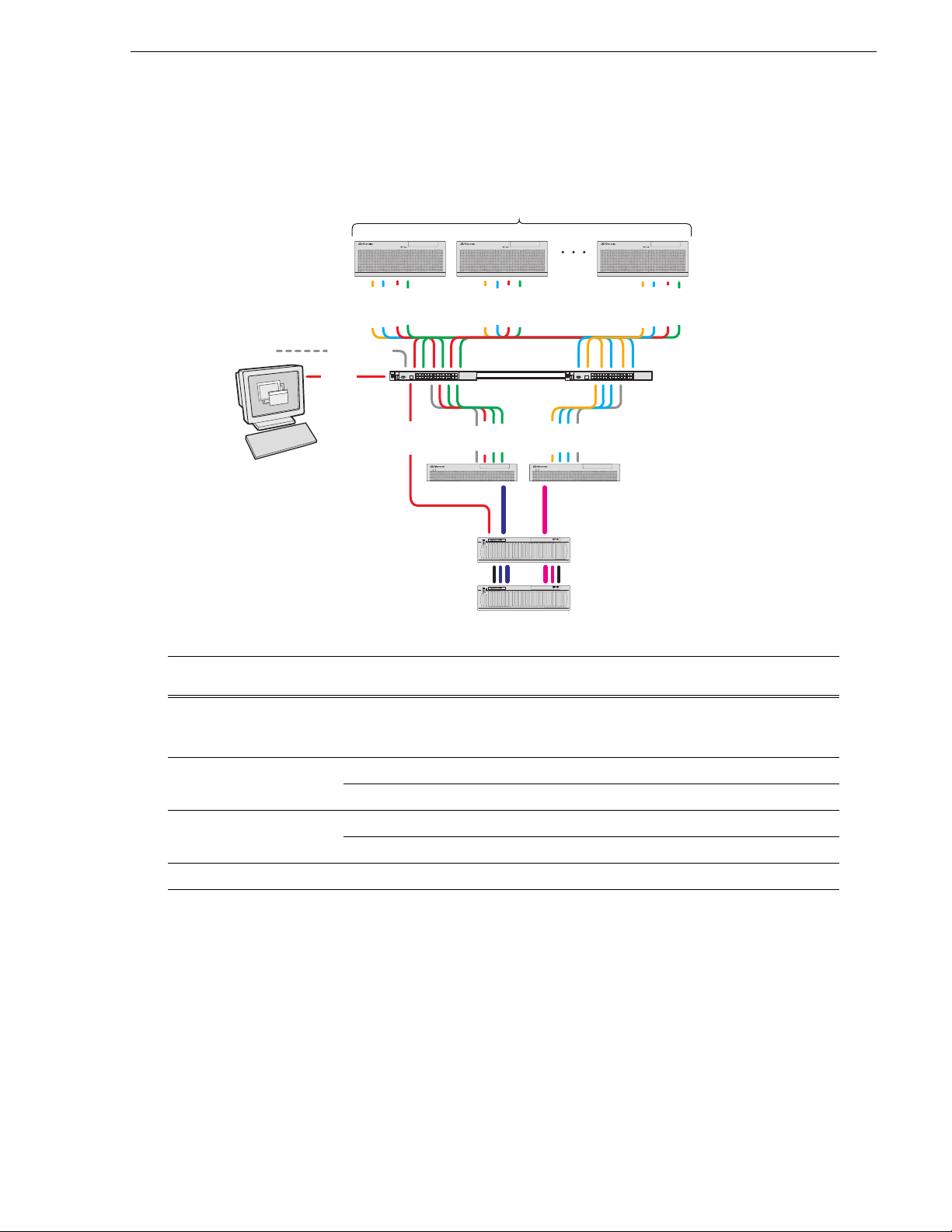
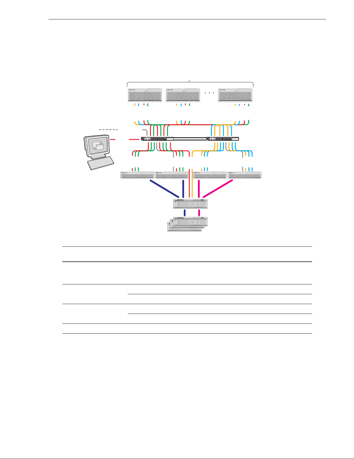
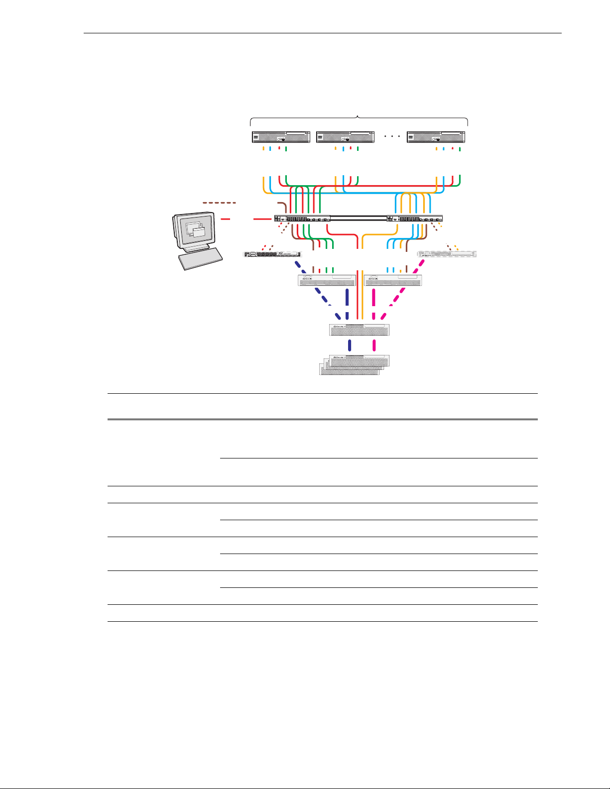
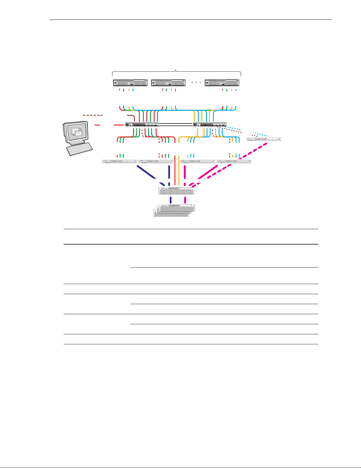
Level 2 Redundant K2 SAN
K2 Media Clients
! ! !
Level 2 Redundant K2 SAN
Control A
Control B
Media A
Media B
FTP/streaming
Control
A B
Control
Control point PC
AB
To cable this K2 SAN
device…
Of this model or
platform…
K2 client K2 Media Client,
including SDA-00,
SD-00, and HD-00.
Control A
Control B
Media B
Media A
Control A
Control B
Media B
Media A
Gigabit Ethernet
switches
FTP
Control
Media
Media
ISLs
Control
Media
Media
FTP
K2 Media
Servers
Fibre Channel
connections
!
RAID STORAGE
K2
SERVICE
POWER
L2R RAID Primary
Chassis
!
RAID STORAGE
K2
SERVICE
POWER
L2R RAID Expansion
Chassis (optional)
Turn to these instructions:
“K2 Media Client for redundant K2 SAN” on page 25
Gigabit Ethernet Switch HP 3400cl series “3400cl HP GigE switch for redundant K2 SAN” on page 29
HP 2900 series “29xx HP GigE switch for redundant K2 SAN” on page 30
K2 Media Server Dell 2850 “Dell 2850 for redundant K2 SAN” on page 33
Dell 2950 “Dell 2950 for redundant K2 SAN” on page 38
K2 RAID Level 2 K2 RAID “K2 RAID for Level 2 redundant K2 SAN” on page 54
This manual documents the default GigE switch configuration. Other configurations are available,
depending on your port count and FTP bandwidth requirements. Refer to the K2 Storage System
Instruction Manual or the K2 SAN Installation and Configuration Guide for more information.
01 April 2010 K2 Storage Cabling Guide 9
Page 10
Chapter 1 Start with the K2 storage system diagram
K2 Media Clients
Gigabit Ethernet Switch
FTP
Control
Media
Control
Media
Control
Media
Control
Control
Media
Control
Media
Media
Media
Control point PC
L3 RAID Primary
Chassis
L3 RAID Expansion
Chassis (optional)
K2 Media
Servers
12
Fibre Channel
connections
Control
FTP/streaming
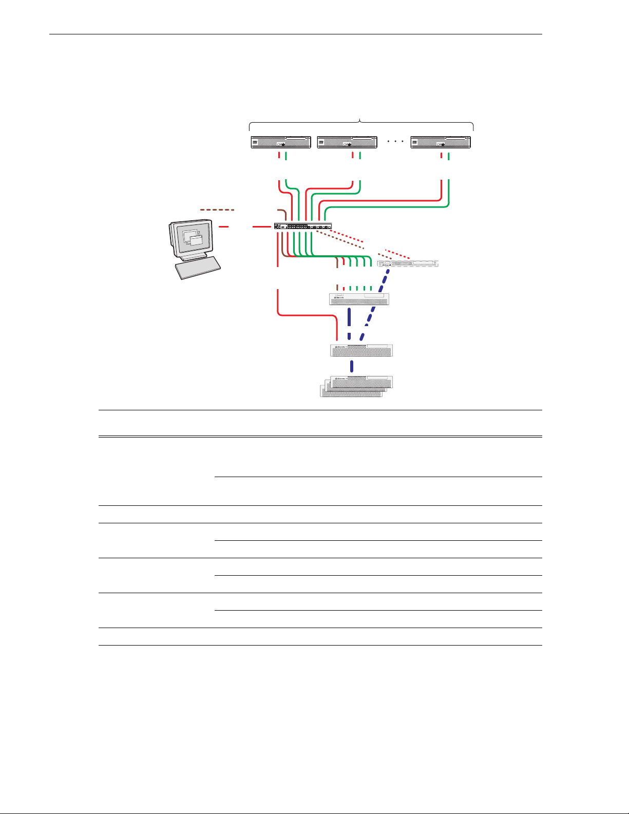
Level 3 Basic K2 SAN
! ! !
!
RAID STORAGE
K2
SERVICE
POWER
!
RAID STORAGE
K2
SERVICE
POWER
!
RAID STORAGE
K2
SERVICE
POWER
!
RAID STORAGE
K2
SERVICE
POWER
To cable this K2 SAN
device…
K2 client K2 Media Client,
Of this model or
platform…
Turn to these instructions:
“K2 Media Client for basic K2 SAN” on page 24
including SDA-00,
SD-00, and HD-00.
Gigabit Ethernet Switch HP 3400cl series “3400cl HP GigE switch for basic K2 SAN” on page 28
HP 2900 series “29xx HP GigE switch for basic K2 SAN” on page 29
K2 Media Server Dell 2850 “Dell 2850 for basic K2 SAN” on page 33
Dell 2950 “Dell 2950 for Level 3 basic K2 SAN” on page 39
K2 RAID Level 3 K2 RAID “K2 RAID for basic K2 SAN” on page 55
This manual documents the default GigE switch configuration. Other configurations are available,
depending on your port count and FTP bandwidth requirements. Refer to the K2 Storage System
Instruction Manual or the K2 SAN Installation and Configuration Guide for more information.
10 K2 Storage Cabling Guide 01 April 2010
Page 11
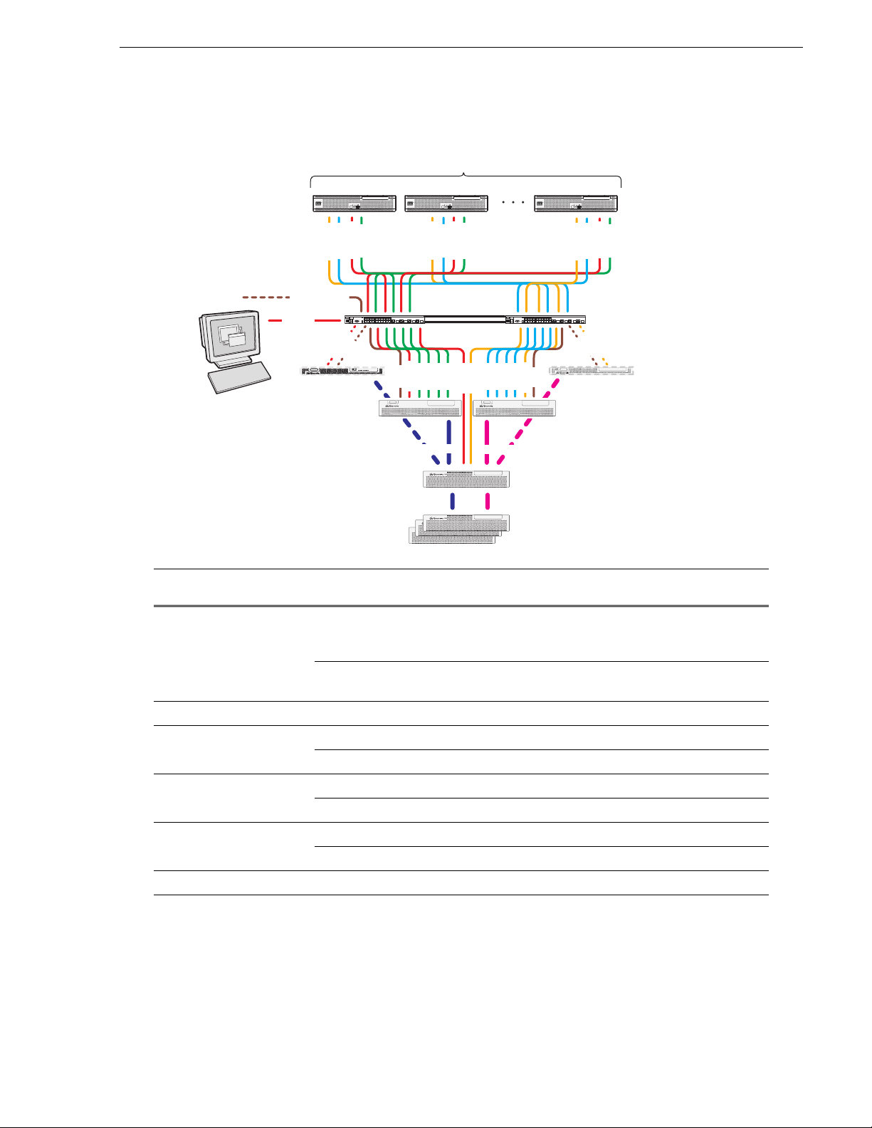
Level 3 Redundant K2 SAN
K2 Media Clients
! ! !
Level 3 Redundant K2 SAN
Control A
Control B
Media A
Media B
Gigabit Ethernet
Switches
Control
Media
Media
FTP
K2 Media
Servers
Control point PC
FTP/streaming
Control
Control
Control A
Control B
Media A
Media B
AB
Media
Media
1A
Control A
Control B
Media B
Media A
ISLs
FTP
Control
Media
Media
Control
Control
Control
Media
Media
2A 1B 2B
Fibre Channel
!
RAID STORAGE
K2
SERVICE
POWER
connections
L3R RAID Primary
Chassis
!
RAID STORAGE
K2
SERVICE
POWER
!
RAID STORAGE
K2
SERVICE
POWER
L3R RAID Expansion
!
RAID STORAGE
K2
SERVICE
POWER
Chassis (optional)
To cable this K2 SAN
device…
K2 client K2 Media Client,
Of this model or
platform…
Turn to these instructions:
“K2 Media Client for redundant K2 SAN” on page 25
including SDA-00,
SD-00, and HD-00.
Gigabit Ethernet Switch HP 3400cl series “3400cl HP GigE switch for redundant K2 SAN” on page 29
HP 2900 series “29xx HP GigE switch for redundant K2 SAN” on page 30
K2 Media Server Dell 2850 “Dell 2850 for redundant K2 SAN” on page 33
Dell 2950 “Dell 2950 for Level 3 redundant K2 SAN” on page 40
K2 RAID Level 3 K2 RAID “K2 RAID for redundant K2 SAN” on page 56
This manual documents the default GigE switch configuration. Other configurations are available,
depending on your port count and FTP bandwidth requirements. Refer to the K2 Storage System
Instruction Manual or the K2 SAN Installation and Configuration Guide for more information.
01 April 2010 K2 Storage Cabling Guide 11
Page 12
Chapter 1 Start with the K2 storage system diagram
RAID Primary
Chassis
RAID Expansion
Chassis (optional)
K2 Media
Server
K2 clients
Gigabit Ethernet Switch
Control
Media
Control
Media
Control
FTP
Media
Control point PC
Control
Control
FTP/streaming
Control
Media
Fibre
Channel
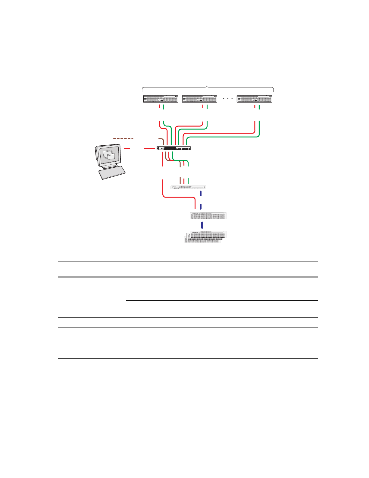
Level 10 Basic K2 SAN
To cable this K2 SAN
device…
Of this model or
platform…
K2 client K2 Media Client,
including SDA-00,
SD-00, and HD-00.
K2SUMMIT
PRODUCTION CLIENT
K2 MEDIA SERVER
!
K2SUMMIT
PRODUCTION CLIENT
K2 SAS STORAGE
!
K2 SAS STORAGE
!
K2 SAS STORAGE
!
K2 SAS STORAGE
Turn to these instructions:
“K2 Media Client for basic K2 SAN” on page 24
K2SUMMIT
PRODUCTION CLIENT
12 K2 Storage Cabling Guide 01 April 2010
K2 Summit
“K2 Summit Production Client for basic K2 SAN” on page 25
Production Client
Gigabit Ethernet Switch HP 2900 series “29xx HP GigE switch for basic K2 SAN” on page 29
K2 Media Server Dell 1950 “Dell 1950 GS for Level 10 basic K2 SAN” on page 34
Dell R610 “Dell R610 GS for Level 10 basic K2 SAN” on page 42
K2 RAID Level 10 K2 RAID “K2 RAID for Level 10 basic K2 SAN” on page 57
This manual documents the default GigE switch configuration. Other configurations are available,
depending on your port count and FTP bandwidth requirements. Refer to the K2 Storage System
Instruction Manual or the K2 SAN Installation and Configuration Guide for more information.
Page 13
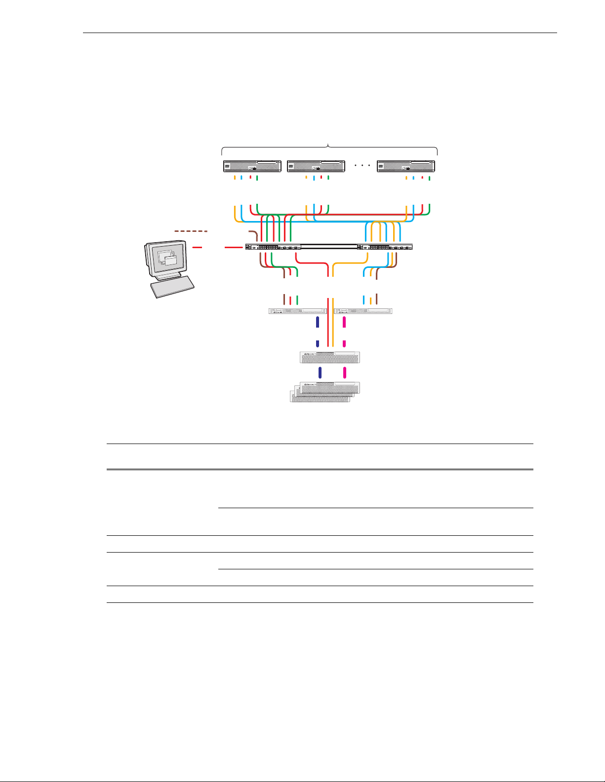
Level 10 Redundant K2 SAN
RAID Primary
Chassis
RAID Expansion
Chassis (optional)
K2 Media
Servers
AB
BA
Gigabit Ethernet
Switches
Control B
Media B
Control A
Media A
Control A
Media A
Control B
Media B
Control
FTP
Media
Control
FTP
Media
Control point PC
K2 clients
Control
ISLs
Control
Control
FTP/streaming
Control B
Media B
Control A
Media A
Fibre
Channel
Fibre
Channel
Level 10 Redundant K2 SAN
K2SUMMIT
PRODUCTION CLIENT
K2SUMMIT
PRODUCTION CLIENT
K2 MEDIA SERVER K2 MEDIA SERVER
K2 SAS STORAGE
!
K2 SAS STORAGE
!
K2 SAS STORAGE
!
K2 SAS STORAGE
!
K2SUMMIT
PRODUCTION CLIENT
To cable this K2 SAN
device…
K2 client K2 Media Client,
Of this model or
platform…
Turn to these instructions:
“K2 Media Client for redundant K2 SAN” on page 25
including SDA-00,
SD-00, and HD-00.
K2 Summit
Production Client
“K2 Summit Production Client for redundant K2 SAN” on
page 26
Gigabit Ethernet Switch HP 2900 series “29xx HP GigE switch for redundant K2 SAN” on page 30
K2 Media Server Dell 1950 “Dell 1950 GS for Level 10 redundant K2 SAN” on page 34
Dell R610 “Dell R610 GS for Level 10 redundant K2 SAN” on page 42
K2 RAID Level 10 K2 RAID “K2 RAID for Level 10 redundant K2 SAN” on page 58
This manual documents the default GigE switch configuration. Other configurations are available,
depending on your port count and FTP bandwidth requirements. Refer to the K2 Storage System
Instruction Manual or the K2 SAN Installation and Configuration Guide for more information.
01 April 2010 K2 Storage Cabling Guide 13
Page 14
Chapter 1 Start with the K2 storage system diagram
Level 20 Basic K2 SAN
K2 clients
Control
FTP/streaming
Control
Control
Control point PC
RAID Primary
RAID Expansion
Chassis (optional)
To cable this K2 SAN
device…
Of this model or
platform…
K2 client K2 Media Client,
including SDA-00,
SD-00, and HD-00.
K2SUMMIT
PRODUCTION CLIENT
Media
K2SUMMIT
PRODUCTION CLIENT
Control
Media
Gigabit Ethernet Switch
Con
tr
o
l
FT
Control
Media
FTP
Fibre Channel
!
P
Media
K2 MEDIA SERVER
K2 SAS STORAGE
K2 MEDIA SERVER
K2 Media Server
Chassis
K2 SAS STORAGE
!
K2 SAS STORAGE
!
K2 SAS STORAGE
!
Turn to these instructions:
“K2 Media Client for basic K2 SAN” on page 24
K2SUMMIT
PRODUCTION CLIENT
Control
Media
NH Server
(optional)
K2 Summit
“K2 Summit Production Client for basic K2 SAN” on page 25
Production Client
Gigabit Ethernet Switch HP 2900 series “29xx HP GigE switch for basic K2 SAN” on page 29
K2 Media Server Dell 1950 “Dell 1950 GS for Level 20 basic K2 SAN” on page 35
Dell R610 “Dell R610 GS for Level 20 basic K2 SAN” on page 42
NH1 K2 Media Server
(optional)
NH1-10GE K2 Media
Server (optional)
Dell 1950 “Dell 1950 NH1 for online K2 SAN” on page 46
Dell R610 “Dell R610 NH1 for online K2 SAN” on page 47
Dell 1950 “Dell 1950 NH1-10GE for online K2 SAN” on page 49
Dell R610 “Dell R610 NH1-10GE for online K2 SAN” on page 50
K2 RAID Level 20 K2 RAID “K2 RAID for Level 20 basic K2 SAN” on page 59
This manual documents the default GigE switch configuration. Other configurations are available,
depending on your port count and FTP bandwidth requirements. Refer to the K2 Storage System
Instruction Manual or the K2 SAN Installation and Configuration Guide for more information.
Multiple NH servers must be of the same type, either all NH1-10GE or all NH1.
14 K2 Storage Cabling Guide 01 April 2010
Page 15
Level 20 Redundant K2 SAN
RAID Primary
Chassis
RAID Expansion
Chassis (optional)
K2 Media
Servers
NH Servers
(optional)
A
B
BA
Gigabit Ethernet
Switches
Fibre Channel
Control B
Media B
Control A
Media A
Control A
Media A
Control B
Media B
Control
FTP
Media
Media
Control
FTP
Media
Media
Control point PC
K2 clients
Control
ISLs
Control
Control
FTP/streaming
Control B
Media B
Control A
Media A
Fibre Channel
Control
FTP
Contro
l
FTP
Level 20 Redundant K2 SAN
To cable this K2 SAN
device…
Of this model or
platform…
K2 client K2 Media Client,
including SDA-00,
SD-00, and HD-00.
K2SUMMIT
PRODUCTION CLIENT
MEDIA SERVER
K2SUMMIT
PRODUCTION CLIENT
K2 MEDIA SERVER K2 MEDIA SERVER
K2 SAS STORAGE
!
K2 SAS STORAGE
!
K2 SAS STORAGE
!
K2 SAS STORAGE
!
Turn to these instructions:
“K2 Media Client for redundant K2 SAN” on page 25
K2SUMMIT
PRODUCTION CLIENT
K2 MEDIA SERVER
K2 Summit
Production Client
“K2 Summit Production Client for redundant K2 SAN” on
page 26
Gigabit Ethernet Switch HP 2900 series “29xx HP GigE switch for redundant K2 SAN” on page 30
K2 Media Server Dell 1950 “Dell 1950 GS for Level 20 redundant K2 SAN” on page 35
NH1 K2 Media Server
(optional)
NH1-10GE K2 Media
Server (optional)
K2 RAID Level 20 K2 RAID “K2 RAID for Level 20 redundant K2 SAN” on page 60
This manual documents the default GigE switch configuration. Other configurations are available,
depending on your port count and FTP bandwidth requirements. Refer to the K2 Storage System
Instruction Manual or the K2 SAN Installation and Configuration Guide for more information.
Multiple NH servers must be of the same type, either all NH1-10GE or all NH1.
Dell R610 “Dell R610 GS for Level 20 redundant K2 SAN” on page 43
Dell 1950 “Dell 1950 NH1 for online K2 SAN” on page 46
Dell R610 “Dell R610 NH1 for online K2 SAN” on page 47
Dell 1950 “Dell 1950 NH1-10GE for online K2 SAN” on page 49
Dell R610 “Dell R610 NH1-10GE for online K2 SAN” on page 50
01 April 2010 K2 Storage Cabling Guide 15
Page 16
Chapter 1 Start with the K2 storage system diagram
Level 30 Basic K2 SAN
K2 clients
Control
FTP/streaming
Control
Control
Control point PC
RAID Primary
RAID Expansion
Chassis (optional)
To cable this K2 SAN
device…
Of this model or
platform…
K2 client K2 Media Client,
including SDA-00,
SD-00, and HD-00.
K2 Summit
Production Client
K2SUMMIT
PRODUCTION CLIENT
Media
K2SUMMIT
PRODUCTION CLIENT
Control
Media
K2SUMMIT
PRODUCTION CLIENT
Control
Media
Gigabit Ethernet Switch
Con
tr
o
l
FT
Control
Media
FTP
Fibre Channel
!
Media
Media
P
Media
K2 MEDIA SERVER
K2 Media Server
K2 SAS STORAGE
K2 MEDIA SERVER
NH Server
(optional)
Chassis
K2 SAS STORAGE
!
K2 SAS STORAGE
!
K2 SAS STORAGE
!
Turn to these instructions:
“K2 Media Client for basic K2 SAN” on page 24
“K2 Summit Production Client for basic K2 SAN” on page 25
Gigabit Ethernet Switch HP 2900 series “29xx HP GigE switch for basic K2 SAN” on page 29
K2 Media Server Dell 2950 “Dell 2950 LS for basic K2 SAN” on page 41
Dell R710 “Dell R710 LS for basic K2 SAN” on page 44
NH1 K2 Media Server
(optional)
NH1-10GE K2 Media
Server (optional)
Dell 1950 “Dell 1950 NH1 for online K2 SAN” on page 46
Dell R610 “Dell R610 NH1 for online K2 SAN” on page 47
Dell 1950 “Dell 1950 NH1-10GE for online K2 SAN” on page 49
Dell R610 “Dell R610 NH1-10GE for online K2 SAN” on page 50
K2 RAID Level 30 K2 RAID “K2 RAID for Level 30 basic K2 SAN” on page 61
This manual documents the default GigE switch configuration. Other configurations are available,
depending on your port count and FTP bandwidth requirements. Refer to the K2 Storage System
Instruction Manual or the K2 SAN Installation and Configuration Guide for more information.
Multiple NH servers must be of the same type, either all NH1-10GE or all NH1.
16 K2 Storage Cabling Guide 01 April 2010
Page 17
Level 30 Redundant K2 SAN
RAID Primary
Chassis
RAID Expansion
Chassis (optional)
K2 Media
Servers
NH Servers
(optional)
A
B
BA
Gigabit Ethernet
Switches
Fibre Channel
Control B
Media B
Control A
Media A
Control A
Media A
Control B
Media B
Control
FTP
Media
Media
Media
Media
Control
FTP
Media
Media
Media
Media
Control point PC
K2 clients
Control
ISLs
Control
Control
FTP/streaming
Control B
Media B
Control A
Media A
Fibre Channel
Control
FTP
Contro
l
FTP
Level 30 Redundant K2 SAN
K2SUMMIT
PRODUCTION CLIENT
MEDIA SERVER
To cable this K2 SAN
device…
Of this model or
platform…
K2 client K2 Media Client,
including SDA-00,
SD-00, and HD-00.
K2SUMMIT
PRODUCTION CLIENT
K2 MEDIA SERVER K2 MEDIA SERVER
K2 SAS STORAGE
!
K2 SAS STORAGE
!
K2 SAS STORAGE
!
K2 SAS STORAGE
!
K2SUMMIT
PRODUCTION CLIENT
K2 MEDIA SERVER
Turn to these instructions:
“K2 Media Client for redundant K2 SAN” on page 25
K2 Summit
Production Client
“K2 Summit Production Client for redundant K2 SAN” on
page 26
Gigabit Ethernet Switch HP 2900 series “29xx HP GigE switch for redundant K2 SAN” on page 30
K2 Media Server Dell 2950 “Dell 2950 LS for redundant K2 SAN” on page 41
Dell R710 “Dell R710 LS for redundant K2 SAN” on page 45
NH1 K2 Media Server
(optional)
NH1-10GE K2 Media
Server (optional)
K2 RAID Level 30 K2 RAID “K2 RAID for Level 30 redundant K2 SAN” on page 62
This manual documents the default GigE switch configuration. Other configurations are available,
depending on your port count and FTP bandwidth requirements. Refer to the K2 Storage System
Instruction Manual or the K2 SAN Installation and Configuration Guide for more information.
Multiple NH servers must be of the same type, either all NH1-10GE or all NH1.
Dell 1950 “Dell 1950 NH1 for online K2 SAN” on page 46
Dell R610 “Dell R610 NH1 for online K2 SAN” on page 47
Dell 1950 “Dell 1950 NH1-10GE for online K2 SAN” on page 49
Dell R610 “Dell R610 NH1-10GE for online K2 SAN” on page 50
01 April 2010 K2 Storage Cabling Guide 17
Page 18
Chapter 1 Start with the K2 storage system diagram
Level 35 Basic K2 SAN
K2 clients
K2SUMMIT
PRODUCTION CLIENT
Control
Media
FTP/streaming
Control
Control
Control point PC
L30 RAID Primary
Chassis
RAID Expansion
Chassis (optional)
To cable this K2 SAN
device…
Of this model or
platform…
K2 client K2 Media Client,
including SDA-00,
SD-00, and HD-00.
K2SUMMIT
PRODUCTION CLIENT
Control
Media
K2SUMMIT
PRODUCTION CLIENT
Control
Media
Gigabit Ethernet Switch
Con
tr
o
l
Control
Media
Media
K2 MEDIA SERVER
FTP
Control
Media
Media
FTP
21
K2 MEDIA SERVER
K2 MEDIA SERVER
NH1-10GE
Server
(optional)
GS K2 Media Servers
Fibre Channel
K2 SAS STORAGE
!
K2 SAS STORAGE
!
K2 SAS STORAGE
!
K2 SAS STORAGE
!
Turn to these instructions:
“K2 Media Client for basic K2 SAN” on page 24
K2 Summit
“K2 Summit Production Client for basic K2 SAN” on page 25
Production Client
Gigabit Ethernet Switch HP 2900 series “29xx HP GigE switch for basic K2 SAN” on page 29
K2 Media Server Dell 1950 “Dell 1950 GS for Level 35 basic K2 SAN” on page 36
Dell R610 “Dell R610 GS for Level 35 basic K2 SAN” on page 43
NH1-10GE K2 Media
Server (optional)
Dell 1950 “Dell 1950 NH1-10GE for online K2 SAN” on page 49
Dell R610 “Dell R610 NH1-10GE for online K2 SAN” on page 50
K2 RAID Level 35 K2 RAID “K2 RAID for Level 35 basic K2 SAN” on page 63
This manual documents the default GigE switch configuration. Other configurations are available,
depending on your port count and FTP bandwidth requirements. Refer to the K2 Storage System
Instruction Manual or the K2 SAN Installation and Configuration Guide for more information.
18 K2 Storage Cabling Guide 01 April 2010
Page 19
Level 35 Redundant K2 SAN
NH1-10GE
Server (optional)
Con
tr
o
l
FTP
Fibre Channel
Fibre Channel
L30 RAID Primary
Chassis
RAID Expansion
Chassis (optional)
1A
AB
2A 1B 2B
Gigabit Ethernet Switches
Control A
Media A
Control A
Control B
Media A
Media B
Control B
Media B
Control
FTP
Media
Media
Control
Media
Media
Control
FTP
Media
Media
Control
Media
Media
Control point PC
K2 clients
Control
ISLs
Control
Control
FTP/streaming
Control B
Media B
Control A
Media A
GS K2 Media
Servers
Level 35 Redundant K2 SAN
K2SUMMIT
PRODUCTION CLIENT
K2 MEDIA SERVER K2MEDIA SERVER K2 MEDIA SERVER K2 MEDIA SERVER
!
!
To cable this K2 SAN
device…
Of this model or
platform…
K2 client K2 Media Client,
including SDA-00,
SD-00, and HD-00.
K2SUMMIT
PRODUCTION CLIENT
K2 SAS STORAGE
!
K2 SAS STORAGE
!
K2 SAS STORAGE
K2 SAS STORAGE
K2SUMMIT
PRODUCTION CLIENT
Turn to these instructions:
“K2 Media Client for redundant K2 SAN” on page 25
K2 MEDIA SERVER
K2 Summit
Production Client
“K2 Summit Production Client for redundant K2 SAN” on
page 26
Gigabit Ethernet Switch HP 2900 series “29xx HP GigE switch for redundant K2 SAN” on page 30
K2 Media Server Dell 1950 “Dell 1950 GS for Level 35 redundant K2 SAN” on page 37
Dell R610 “Dell R610 GS for Level 35 redundant K2 SAN” on page 44
NH1-10GE K2 Media
Server (optional)
K2 RAID Level 35 K2 RAID “K2 RAID for Level 35 redundant K2 SAN” on page 64
Dell 1950 “Dell 1950 NH1-10GE for online K2 SAN” on page 49
Dell R610 “Dell R610 NH1-10GE for online K2 SAN” on page 50
This manual documents the default GigE switch configuration. Other configurations are available,
depending on your port count and FTP bandwidth requirements. Refer to the K2 Storage System
Instruction Manual or the K2 SAN Installation and Configuration Guide for more information.
01 April 2010 K2 Storage Cabling Guide 19
Page 20
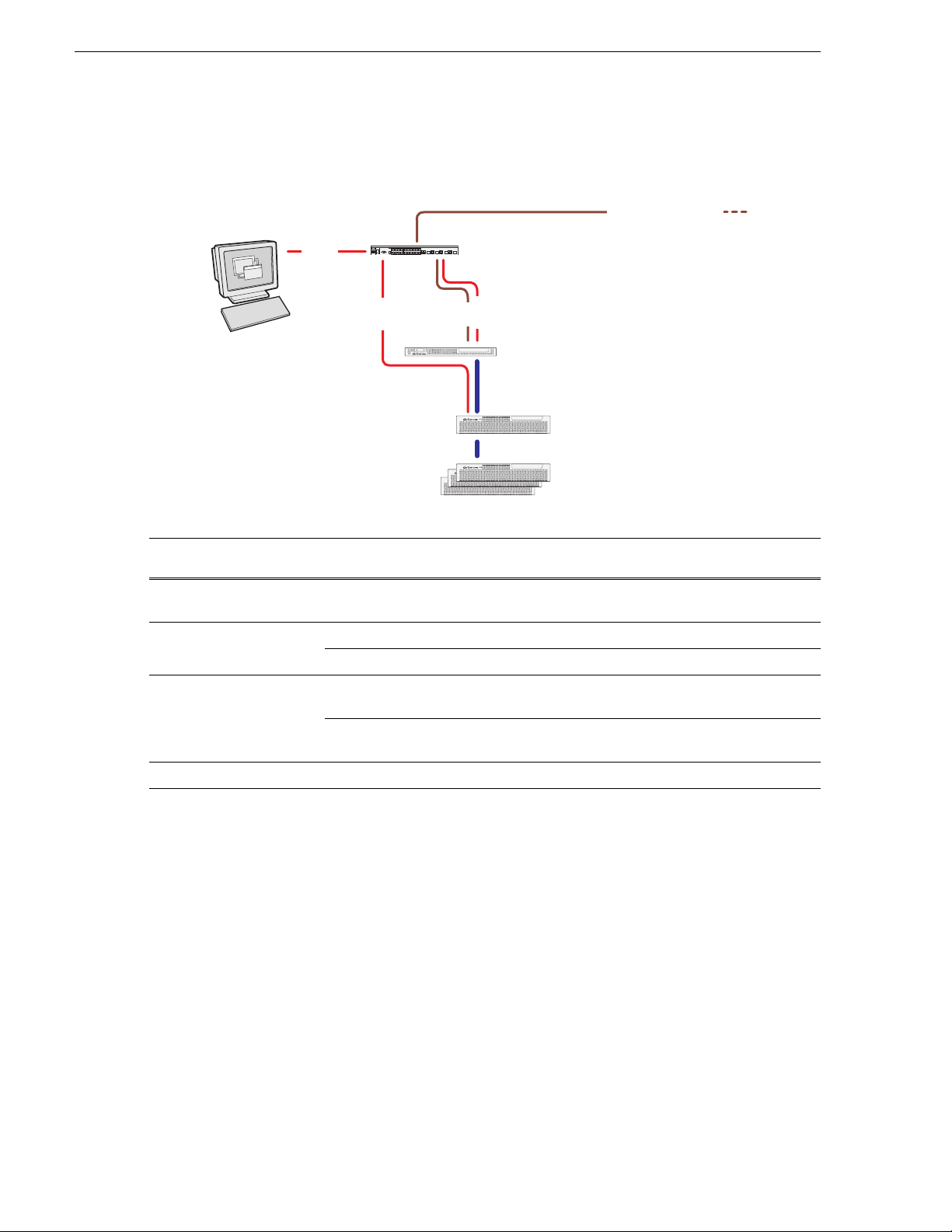
Chapter 1 Start with the K2 storage system diagram
Control
RAID Chassis
(SATA drives)
RAID Expansion Chassis
(SATA drives)
NH K2 Media
Server
Gigabit Ethernet
Switch
Fibre Channel
connection
Control
FTP
Control point PC
Control
FTP to/from online system
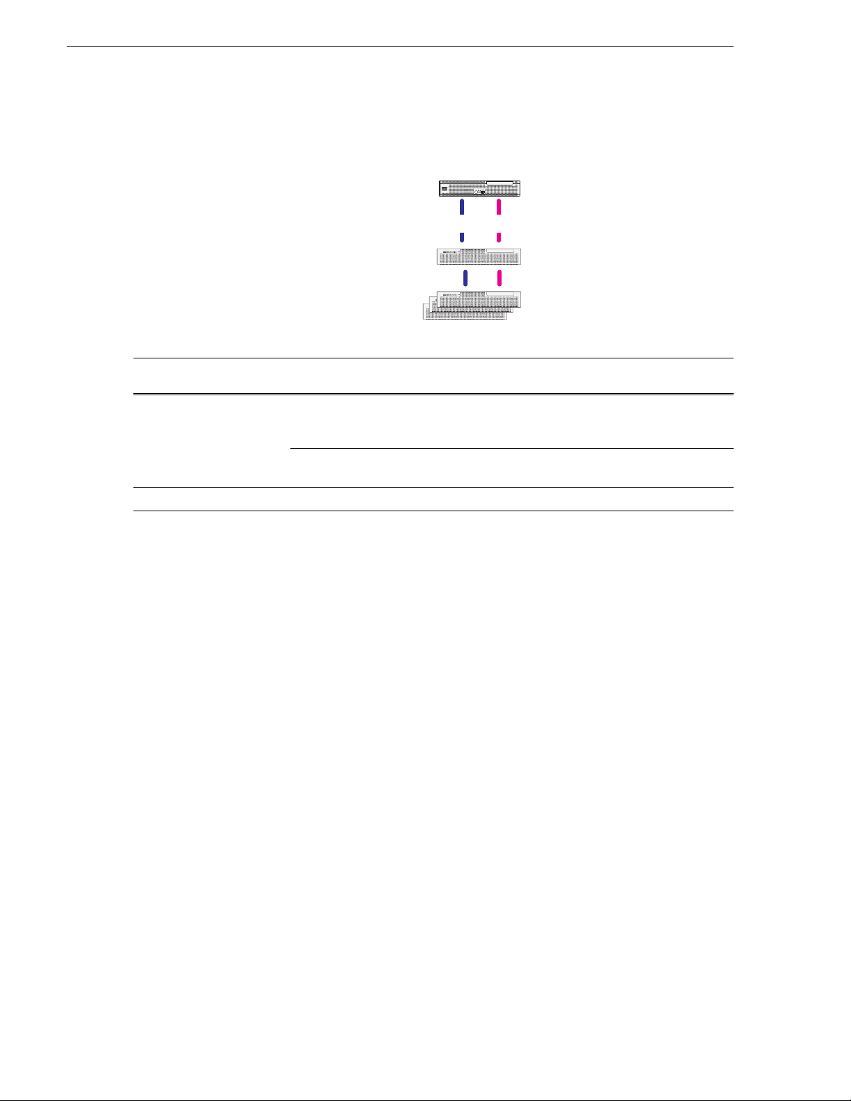
Nearline 10 Basic K2 SAN
K2 MEDIA SERVER
!
K2 SATA STORAGE
!
K2 SATA STORAGE
!
K2 SATA STORAGE
!
K2 SATA STORAGE
To cable this K2 SAN
device…
Of this model or
platform…
Turn to these instructions:
Gigabit Ethernet Switch HP 2900 series “29xx HP GigE switch for basic nearline K2 SAN” on
page 30
NH1 K2 Media Server Dell 1950 “Dell 1950 NH1 for basic nearline K2 SAN” on page 46
Dell R610 “Dell R610 NH1 for basic nearline K2 SAN” on page 47
NH1-10GE K2 Media
Server
Dell 1950 “Dell 1950 NH1-10GE for basic nearline K2 SAN” on
page 49
Dell R610 “Dell R610 NH1-10GE for basic nearline K2 SAN” on
page 50
K2 RAID Level 10 K2 RAID “K2 RAID for Nearline 10 basic K2 SAN” on page 65
20 K2 Storage Cabling Guide 01 April 2010
Page 21
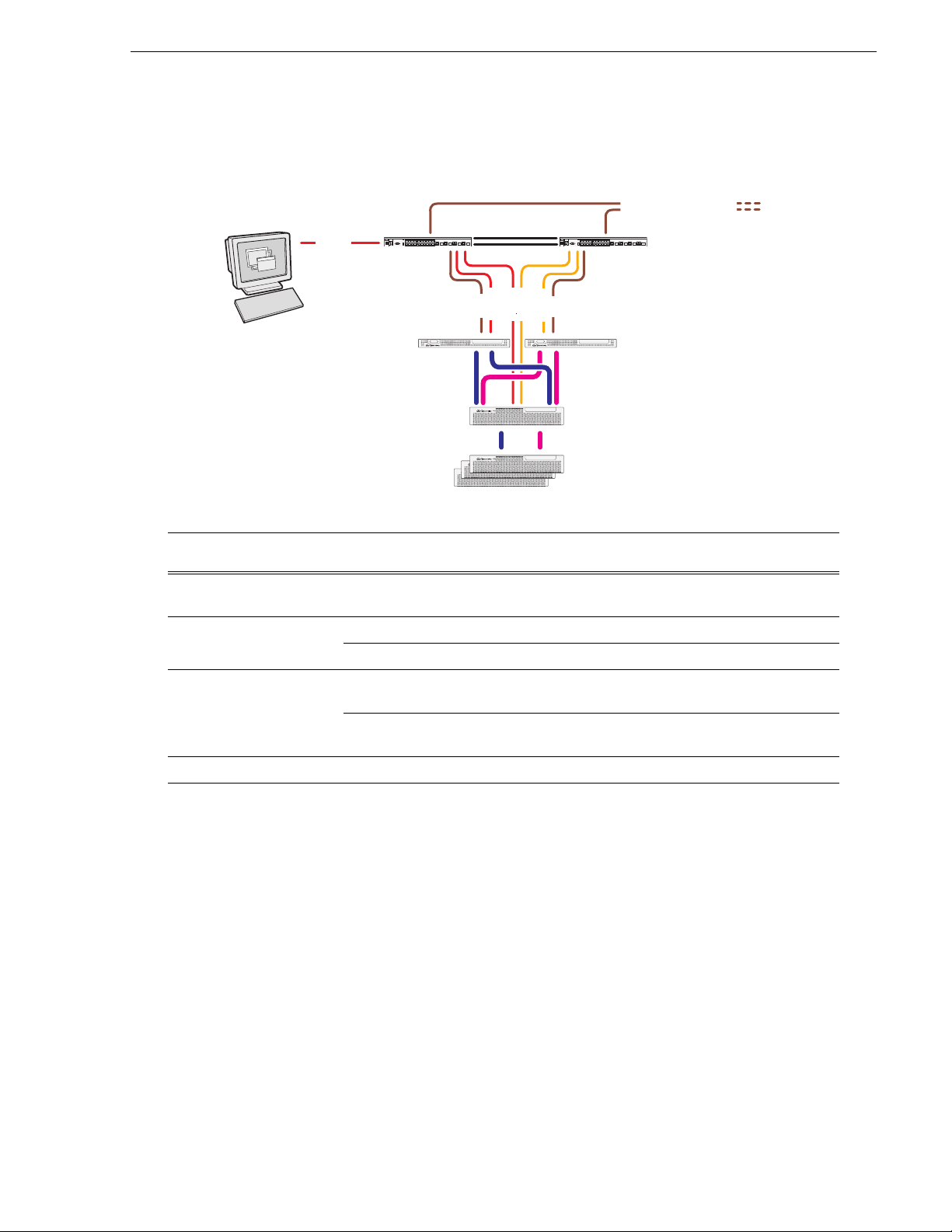
Nearline 10 Redundant K2 SAN
ISLs
Control
Control
RAID Chassis
(SAS drives)
RAID Expansion Chassis
(SATA drives)
NH K2 Media
Servers
Gigabit Ethernet
Switches
Fibre Channel
connections
Control
FTP
Control
FTP
Control point PC
Control
FTP to/from online system
ISLs
A
A
B
B
K2 SATA STORAGE
!
K2 SATA STORAGE
!
K2 SATA STORAGE
!
K2 SATA STORAGE
!
Nearline 10 Redundant K2 SAN
K2 MEDIA SERVERK2 MEDIA SERVER
To cable this K2 SAN
device…
Of this model or
platform…
Turn to these instructions:
Gigabit Ethernet Switch HP 2900 series “29xx HP GigE switch for redundant nearline K2 SAN” on
page 31
NH1 K2 Media Server Dell 1950 “Dell 1950 NH1 for redundant nearline K2 SAN” on page 47
Dell R610 “Dell R610 NH1 for redundant nearline K2 SAN” on page 48
NH1-10GE K2 Media
Server
Dell 1950 “Dell 1950 NH1-10GE for redundant nearline K2 SAN” on
page 50
Dell R610 “Dell R610 NH1-10GE for redundant nearline K2 SAN” on
page 51
K2 RAID Level 10 K2 RAID “K2 RAID for Nearline 10 redundant K2 SAN” on page 66
Redundant NH servers must be of the same type, either both NH1-10GE or both NH1.
01 April 2010 K2 Storage Cabling Guide 21
Page 22
Chapter 1 Start with the K2 storage system diagram
K2 client with direct-connect storage
K2 client
RAID Primary
Chassis
RAID Expansion
Chassis (optional)
Fibre
Channel
!
!
PRODUCTION
K2 SUMMIT
CLIENT
Fibre
Channel
K2 SAS STORAGE
!
K2 SAS STORAGE
!
K2 SAS STORAGE
K2 SAS STORAGE
To cable this K2 device… Of this model or
Turn to these instructions:
platform…
K2 client K2 Media Client,
“K2 Media Client with direct-connect storage” on page 26
including SDA-00,
SD-00, and HD-00.
K2 Summit
Production Client
“K2 Summit Production Client with direct-connect storage”
on page 27
K2 RAID Level 30 K2 RAID “K2 RAID for K2 client direct-connect storage” on page 67
22 K2 Storage Cabling Guide 01 April 2010
Page 23

Chapter 2
Cable K2 devices
As directed by the system diagram for your K2 storage, cable the individual devices
of your K2 system using the instructions in the following sections.
• “Cable K2 client” on page 24
• “Cable Gigabit Ethernet switch” on page 28
• “Cable K2 Media Server” on page 32
• “Cable NH1 K2 Media Server” on page 46
• “Cable NH1-10GE K2 Media Server” on page 49
• “Cable K2 RAID” on page 52
01 April 2010 K2 Storage Cabling Guide 23
Page 24

Chapter 2 Cable K2 devices
!
Cable K2 client
As directed by the system diagram for your K2 storage, cable the K2 client devices
using the instructions in this section.
• “K2 Media Client for basic K2 SAN” on page 24
• “K2 Media Client for redundant K2 SAN” on page 25
• “K2 Summit Production Client for basic K2 SAN” on page 25
• “K2 Summit Production Client for redundant K2 SAN” on page 26
• “K2 Media Client with direct-connect storage” on page 26
• “K2 Summit Production Client with direct-connect storage” on page 27
K2 Media Client for basic K2 SAN
These cabling instructions apply to the following:
• K2 Media Client on a basic (non-redundant) K2 SAN
K2 Media Client model SD-00 is shown. Other models have similar connections.
Refer to each model’s K2 Media Client Quick Start Guide for additional cabling
details.
SDI CH 1
IN OUT
SDI CH 2
IN OUT
SDI CH 3
IN OUT
SDI CH 4
AES/EBU CH 1
IN OUT
1-2
1-2
3-4
3-4
IN IN IN
Push
AES/EBU CH 2
IN OUT
Push
To control port
on GigE switch
IN OUT
OUT OUT OUT OUT
LTC CH 1 LTC CH 2 LTC CH 3 LTC CH 4 UNUSED UNUSED
IN
Push
AES/EBU CH 3
IN OUT
1-2
1-2
3-4
1-2
3-4
3-4
Push
Push
1-2
3-4
AES/EBU CH 4
IN OUT
Push
REF
COMPOSITE LOOP
1-2
1-2
THRU
3-4
3-4
RS-422
Port 3
Port 4
SCSI
To media (iSCSI) port
on GigE switch
GPIO
RS-422
10Bt
Port 1
100Bt
Port 2
1000Bt
24 K2 Storage Cabling Guide 01 April 2010
Page 25

K2 Media Client for redundant K2 SAN
RS-422
Port 3
Port 4
SCSI
RS-422
Port 1
Port 2
10Bt
100Bt
1000Bt
Push
Push
Push
Push
Push
Push
GPIO
!
SDI CH 1
IN OUT
SDI CH 2
IN OUT
SDI CH 3
IN OUT
SDI CH 4
IN OUT
OUT OUT OUT OUT
IN
LTC CH 1 LTC CH 2 LTC CH 3 LTC CH 4 UNUSED UNUSED
IN IN IN
AES/EBU CH 1
IN OUT
1-2
3-4
1-2
3-4
1-2
3-4
1-2
3-4
1-2
3-4
1-2
3-4
1-2
3-4
1-2
3-4
AES/EBU CH 2
IN OUT
AES/EBU CH 3
IN OUT
AES/EBU CH 4
IN OUT
REF
COMPOSITE LOOP
THRU
To control port
on GigE switch A
To media (iSCSI) port
on GigE switch A
To control port
on GigE switch B
To media (iSCSI) port
on GigE switch B
C1
C2 C3 C4
!
OK
~AC
!
OK
~AC
SDI IN1 SDI OUT1 SDI OUT2
LTC I/O
AES AUDIO RS422
SDI OUT1 SDI OUT2
USB/1394 100BT/1000BT
GPI
VGA REF. LOOP THROUGH
AES AUDIO RS422
LTC I/ O
SDI IN2 SDI IN3 SDI IN1 SDI IN2 SDI IN3 SDI IN1 SDI OUT1 SDI OUT2
LTC I/ O
AES AUDIO RS422
SDI OUT1 SDI OUT2
AES AUDIO RS422
LTC I/O
SDI IN2 SDI IN3 SDI IN1 SDI IN2 SDI IN3
To control port
on GigE switch
To media (iSCSI) port
on GigE switch
These cabling instructions apply to the following:
• K2 Media Client on a redundant K2 SAN
K2 Media Client model SD-00 is shown. Other models have similar connections.
Refer to each model’s K2 Media Client Quick Start Guide for additional cabling
details.
K2 Media Client for redundant K2 SAN
K2 Summit Production Client for basic K2 SAN
These cabling instructions apply to the following:
• K2 Summit Production Client on a basic (non-redundant) K2 SAN
Refer to the K2 Summit Production Client Quick Start Guide for additional cabling
details.
01 April 2010 K2 Storage Cabling Guide 25
Page 26

Chapter 2 Cable K2 devices
!
K2 Summit Production Client for redundant K2 SAN
These cabling instructions apply to the following:
• K2 Summit Production Client on a redundant K2 SAN
Refer to the K2 Summit Production Client Quick Start Guide for additional cabling
details.
To media (iSCSI) port
on GigE switch A
SDI IN1 SDI OUT1 SDI OUT2
SDI IN2 SDI IN3 SDI IN1 SDI IN2 SDI IN3 SDI IN1 SDI OUT1 SDI OUT2
AES AUDIO RS422
C1
LTC I/ O
OK
!
~AC
SDI OUT1 SDI OUT2
AES AUDIO RS422
To control port
on GigE switch A
LTC I/O
C2 C3 C4
USB/1394 100BT/1000BT
To media (iSCSI) port
on GigE switch B
SDI IN2 SDI IN3 SDI IN1 SDI IN2 SDI IN3
AES AUDIO RS422
To control port
on GigE switch B
LTC I/ O
GPI
VGA REF. LOOP THROUGH
K2 Media Client with direct-connect storage
These cabling instructions apply to the following:
• K2 Media Client with direct-connect K2 RAID storage
Refer to the K2 Media Client System Guide for additional information about
direct-connect storage.
K2 Media Client model SD-00 is shown. Other models have similar connections.
Refer to each model’s K2 Media Client Quick Start Guide for additional cabling
details.
SDI OUT1 SDI OUT2
AES AUDIO RS422
LTC I/O
OK
!
~AC
K2 Media Client
REF
SDI CH 1
IN OUT
SDI CH 2
IN OUT
SDI CH 3
IN OUT
SDI CH 4
AES/EBU CH 1
IN OUT
1-2
1-2
3-4
3-4
IN IN IN
Push
AES/EBU CH 2
IN OUT
Push
IN OUT
OUT OUT OUT OUT
LTC CH 1 LTC CH 2 LTC CH 3 LTC CH 4 UNUSED UNUSED
IN
Push
AES/EBU CH 3
IN OUT
1-2
1-2
3-4
1-2
3-4
3-4
Push
Push
1-2
3-4
AES/EBU CH 4
IN OUT
1-2
3-4
Push
RS-422
Port 3
Port 4
1-2
3-4
COMPOSITE LOOP
SCSI
GPIO
THRU
RS-422
10Bt
Port 1
100Bt
Port 2
1000Bt
Fibre Channel card can be in a different location than shown, but connections are similar.
To K2 RAID
Controller
To K2 RAID
Controller
26 K2 Storage Cabling Guide 01 April 2010
Page 27

K2 Summit Production Client with direct-connect storage
K2 Summit Production Client with direct-connect storage
These cabling instructions apply to the following:
• K2 Summit Production Client with direct-connect K2 RAID storage
Refer to the K2 System Guide for additional information about direct-connect storage.
Refer to the K2 Summit Production Client Quick Start Guide for additional cabling
details.
K2 Summit Production Client
SDI IN1 SDI OUT1 SDI OUT2
SDI IN2 SDI IN3 SDI IN1 SDI IN2 SDI IN3 SDI IN1 SDI OUT1 SDI OUT2
AES AUDIO RS422
C1
LTC I/O
OK
!
~AC
SDI OUT1 SDI OUT2
AES AUDIO RS422
LTC I/ O
C2 C3 C4
SDI IN2 SDI IN3 SDI IN1 SDI IN2 SDI IN3
AES AUDIO RS422
USB/1394 100BT/1000BT
VGA REF. LOOP THROUGH
LTC I/ O
GPI
SDI OUT1 SDI OUT2
AES AUDIO RS422
LTC I/O
OK
!
~AC
To K2 RAID
Controller
To K2 RAID
Controller
01 April 2010 K2 Storage Cabling Guide 27
Page 28

Chapter 2 Cable K2 devices
Media Ports
Control Ports
1 - 19 odd
2 - 20 even
Cable Gigabit Ethernet switch
As directed by the system diagram for your K2 SAN’s level, cable the switch or
switches for your K2 SAN using the instructions in this section.
• “3400cl HP GigE switch for basic K2 SAN” on page 28
• “3400cl HP GigE switch for redundant K2 SAN” on page 29
• “29xx HP GigE switch for basic K2 SAN” on page 29
• “29xx HP GigE switch for redundant K2 SAN” on page 30
• “29xx HP GigE switch for basic nearline K2 SAN” on page 30
• “29xx HP GigE switch for redundant nearline K2 SAN” on page 31
3400cl HP GigE switch for basic K2 SAN
These cabling instructions apply to the following:
• HP 3400cl series Gigabit Ethernet switch on a basic (non-redundant) online K2
SAN.
To the media ports make one connection from each K2 Media Client or other iSCSI
client and two connections from the media server.
To the control ports make a connection from each K2 Media Client or other iSCSI
client, from the media server, from the RAID storage chassis, and from the control
point PC.
28 K2 Storage Cabling Guide 01 April 2010
Page 29

3400cl HP GigE switch for redundant K2 SAN
Media Ports
Control Ports
1 - 19 odd
2 - 20 even
ISLs
Control ports
Media (iSCSI) ports
10 Gig connections to
rear of switch for optional
NH1-10GE servers
Control ports are for control connections from K2 clients, Aurora
products, automation, etc., as well as FTP connections from Grass
Valley and 3rd party systems.
3400cl HP GigE switch for redundant K2 SAN
These cabling instructions apply to the following:
• HP 3400cl series Gigabit Ethernet switch on a redundant online K2 SAN.
To the media ports on switch A, make one media connection from each K2 Media
Client or other iSCSI client and make two connections from media server A.
To the media ports on switch B, make the second media connection from each K2
Media Client or other iSCSI client and make two connections from media server B.
To the control ports on switch A, make one control connection from each K2 Media
Client or other iSCSI client, from media server A, from the RAID storage chassis,
and from the control point PC.
To the control ports on switch B, make the second control connection from each
K2 Media Client or other iSCSI client and the control connection from media
server B.
Interconnect switch A and switch B with two 10 Gig ISLs.
29xx HP GigE switch for basic K2 SAN
These cabling instructions apply to the following:
• HP 29xx series Gigabit Ethernet switch on a basic (non-redundant) online K2
SAN.
NOTE: NH1-10GE server not supported on Level 10 K2 SAN.
01 April 2010 K2 Storage Cabling Guide 29
Page 30

Chapter 2 Cable K2 devices
Control ports
Media (iSCSI) ports
Control ports
Media (iSCSI) ports
B
A
Inter-Switch Links (ISLs)
Control ports are for control connections from K2 clients, Aurora
products, automation, etc., as well as FTP connections from Grass
Valley and 3rd party systems.
10 Gig connections to
rear of switch for optional
NH1-10GE servers
10 Gig FTP connection
to rear of switch for
NH1-10GE server
Ports are for control connections as well as FTP connections from
Grass Valley and 3rd party systems.
29xx HP GigE switch for redundant K2 SAN
These cabling instructions apply to the following:
• HP 29xx series Gigabit Ethernet switch on a basic (non-redundant) online K2
SAN.
NOTE: NH1-10GE server not supported on Level 10 K2 SAN.
29xx HP GigE switch for basic nearline K2 SAN
These cabling instructions apply to the following:
• HP 29xx series Gigabit Ethernet switch on a basic (non-redundant) nearline K2
SAN.
30 K2 Storage Cabling Guide 01 April 2010
Page 31

29xx HP GigE switch for redundant nearline K2 SAN
29xx HP GigE switch for redundant nearline K2 SAN
These cabling instructions apply to the following:
• HP 29xx series Gigabit Ethernet switch on a redundant nearline K2 SAN.
A
10 Gig FTP connections
to rear of switch for
NH1-10GE servers
Inter-Switch Links (ISLs)
B
Ports are for control connections as well as FTP connections from
Grass Valley and 3rd party systems.
01 April 2010 K2 Storage Cabling Guide 31
Page 32

Chapter 2 Cable K2 devices
Cable K2 Media Server
As directed by the system diagram for your K2 SAN’s level, cable the K2 Media
Server or Servers for your K2 SAN using the instructions in this section.
• “Dell 2850 for basic K2 SAN” on page 33
• “Dell 2850 for redundant K2 SAN” on page 33
• “Dell 1950 GS for Level 10 basic K2 SAN” on page 34
• “Dell 1950 GS for Level 10 redundant K2 SAN” on page 34
• “Dell 1950 GS for Level 20 basic K2 SAN” on page 35
• “Dell 1950 GS for Level 20 redundant K2 SAN” on page 35
• “Dell 1950 GS for Level 35 basic K2 SAN” on page 36
• “Dell 1950 GS for Level 35 redundant K2 SAN” on page 37
• “Dell 2950 for basic K2 SAN” on page 38
• “Dell 2950 for redundant K2 SAN” on page 38
• “Dell 2950 for Level 3 basic K2 SAN” on page 39
• “Dell 2950 for Level 3 redundant K2 SAN” on page 40
• “Dell 2950 LS for basic K2 SAN” on page 41
• “Dell 2950 LS for redundant K2 SAN” on page 41
• “Dell R610 GS for Level 10 basic K2 SAN” on page 42
• “Dell R610 GS for Level 10 redundant K2 SAN” on page 42
• “Dell R610 GS for Level 20 basic K2 SAN” on page 42
• “Dell R610 GS for Level 20 redundant K2 SAN” on page 43
• “Dell R610 GS for Level 35 basic K2 SAN” on page 43
• “Dell R610 GS for Level 35 redundant K2 SAN” on page 44
• “Dell R710 LS for basic K2 SAN” on page 44
• “Dell R710 LS for redundant K2 SAN” on page 45
32 K2 Storage Cabling Guide 01 April 2010
Page 33

Dell 2850 for basic K2 SAN
iSCSI interface
Power
Keyboard/Mouse
GigE
3
2
1
Fibre Channel
VGA monitor
GigE
(FTP)
(control)
ports
(GigE media)
port 1
(USB)
Serial port
port 2
iSCSI interface
Power
Keyboard/Mouse
GigE
3
2
1
Fibre Channel
VGA monitor
GigE
(FTP)
(control)
ports
(GigE media)
port 1
(USB)
Serial port
port 2
These cabling instructions apply to the following:
• Dell 2850 PowerEdge Server on a basic (non-redundant) online K2 SAN.
Connect the two iSCSI interface adapters to media ports on the GigE switch.
Connect the motherboard GigE port 1 and GigE port 2 to control ports on the
GigE switch.
Connect one of the Fibre Channel ports to the RAID storage device.
Dell 2850 for basic K2 SAN
Dell 2850 for redundant K2 SAN
These cabling instructions apply to the following:
• Dell 2850 PowerEdge Server on a redundant online K2 SAN.
Connect the two iSCSI interface adapters to media ports on the GigE switch.
Connect the motherboard GigE port 1 and GigE port 2 to control ports on the
GigE switch.
Connect one of the Fibre Channel ports to the RAID storage device.
Make a direct connection between the serial ports of the two redundant servers.
For Level 3 redundant, connect server 1A to server 1B, and connect server 2A
to server 2B.
01 April 2010 K2 Storage Cabling Guide 33
Page 34

Chapter 2 Cable K2 devices
Dell 1950 GS for Level 10 basic K2 SAN
These cabling instructions apply to the following:
• Dell 1950 PowerEdge Server on a Level 10 basic (non-redundant) K2 SAN.
Fibre Channel
to RAID controller
To media (iSCSI)
port on GigE switch
12
Gb 2Gb 1
To control por t
on GigE switch
FTP: To control port
on GigE switch
Dell 1950 GS for Level 10 redundant K2 SAN
These cabling instructions apply to the following:
• Dell 1950 PowerEdge Server on a Level 10 redundant K2 SAN.
A
Heartbeat
cable
(serial)
Fibre Channel
to RAID controller 0
12
To control por t
on GigE switch A
Fibre Channel
to RAID controller 1
To media (iSCSI)
port on GigE switch A
Gb 2Gb 1
FTP: To control port
on GigE switch A
To media (iSCSI)
port on GigE switch B
B
12
Gb 2Gb 1
To control por t
on GigE switch B
FTP: To control port
on GigE switch B
34 K2 Storage Cabling Guide 01 April 2010
Page 35

Dell 1950 GS for Level 20 basic K2 SAN
12
Gb 2Gb 1
To media (iSCSI)
ports on GigE switch
Fibre Channel
to RAID controller
To control por t
on GigE switch
FTP: To control port
on GigE switch
Dell 1950 GS for Level 20 basic K2 SAN
These cabling instructions apply to the following:
• Dell 1950 PowerEdge Server on a Level 20 basic (non-redundant) K2 SAN.
Dell 1950 GS for Level 20 redundant K2 SAN
These cabling instructions apply to the following:
• Dell 1950 PowerEdge Server on a Level 20 redundant K2 SAN.
A
B
Heartbeat
cable
(serial)
Fibre Channel
to RAID controller 0
12
To control por t
on GigE switch A
Fibre Channel
to RAID controller 1
12
To control por t
on GigE switch B
To media (iSCSI)
ports on GigE switch A
Gb 2Gb 1
FTP: To control port
on GigE switch A
To media (iSCSI)
ports on GigE switch B
Gb 2Gb 1
FTP: To control port
on GigE switch B
01 April 2010 K2 Storage Cabling Guide 35
Page 36

Chapter 2 Cable K2 devices
To control port
on GigE switch
FTP: To control port
on GigE switch.
Do not use if optional NH server
is present to handle FTP traffic.
1
2
To media (iSCSI)
ports on GigE switch
To control port
on GigE switch
Media File System Server
Metadata (database) Server
iSCSI Bridge
Roles:
iSCSI Bridge
NAS Server
(FTP Server if NH
server is not present)
Roles:
Fibre Channel
to RAID controller
To media (iSCSI)
ports on GigE switch
Fibre Channel
to RAID controller
Dell 1950 GS for Level 35 basic K2 SAN
These cabling instructions apply to the following:
• Dell 1950 PowerEdge Server on a Level 35 basic (non-redundant) K2 SAN.
12
Gb 2Gb 1
12
Gb 2Gb 1
36 K2 Storage Cabling Guide 01 April 2010
Page 37

Dell 1950 GS for Level 35 redundant K2 SAN
To control port
on GigE switch A
FTP: To control port
on GigE switch A.
Do not use if optional NH server
is present to handle FTP traffic.
1A
2A
1B
2B
Heartbeat
cable
(serial)
To media (iSCSI)
ports on GigE switch A
To control port
on GigE switch A
Media File System Server
Metadata (database) Server
iSCSI Bridge
Roles:
Media File System Server
Metadata (database) Server
iSCSI Bridge
Roles:
iSCSI Bridge
NAS Server
(FTP Server if NH
server is not present)
Roles:
Fibre Channel
to RAID controller
To media (iSCSI)
ports on GigE switch B
To control port
on GigE switch B
Fibre Channel
to RAID controller
To media (iSCSI)
ports on GigE switch A
Fibre Channel
to RAID controller
To control port
on GigE switch B
FTP: To control port
on GigE switch B.
Do not use if optional NH server
is present to handle FTP traffic.
iSCSI Bridge
NAS Server
(FTP Server if NH
server is not present)
Roles:
To media (iSCSI)
ports on GigE switch B
Fibre Channel
to RAID controller
Dell 1950 GS for Level 35 redundant K2 SAN
These cabling instructions apply to the following:
• Dell 1950 PowerEdge Server on a Level 35 redundant K2 SAN.
12
Gb 2Gb 1
12
Gb 2Gb 1
12
Gb 2Gb 1
12
Gb 2Gb 1
01 April 2010 K2 Storage Cabling Guide 37
Page 38

Chapter 2 Cable K2 devices
Fibre Channel
to RAID controller
A
To control port
on GigE switch A
FTP: To control port
on GigE switch A
To control port
on GigE switch B
FTP: To control port
on GigE switch B
B
Heartbeat
cable
(serial)
To media (iSCSI)
ports on GigE switch A
To media (iSCSI)
ports on GigE switch B
Fibre Channel
to RAID controller
Dell 2950 for basic K2 SAN
These cabling instructions apply to the following:
• Dell 2950 PowerEdge Server with two iSCSI interface adapters (TOEs) on a basic
(non-redundant) online K2 SAN.
To media (iSCSI)
ports on GigE switch
PCI 2
PCI 1
PCI 3
To control port
on GigE switch
Gb 1 Gb 2
FTP: To control port
on GigE switch
Dell 2950 for redundant K2 SAN
These cabling instructions apply to the following:
• Dell 2950 PowerEdge Server with two iSCSI interface adapters (TOEs) on a
redundant online K2 SAN.
PCI 2
PCI 1
PCI 3
Gb 1 Gb 2
Fibre Channel
to RAID controller
PCI 2
PCI 1
PCI 3
Gb 1 Gb 2
38 K2 Storage Cabling Guide 01 April 2010
Page 39

Dell 2950 for Level 3 basic K2 SAN
Fibre Channel
to RAID controller
Media File System Server
Media Database Server
iSCSI Bridge
Roles:
FTP Server
iSCSI Bridge
NAS Server
Roles:
To control port
on GigE switch
1
2
To control port
on GigE switch
FTP: To control port
on GigE switch
To media (iSCSI)
ports on GigE switch
To media (iSCSI)
ports on GigE switch
Fibre Channel
to RAID controller
These cabling instructions apply to the following:
• Dell 2950 PowerEdge Server with two iSCSI interface adapters (TOEs) on a Level
3 basic (non-redundant) K2 SAN.
PCI 2
PCI 1
PCI 1
PCI 3
Gb 1 Gb 2
PCI 2
PCI 3
Gb 1 Gb 2
Dell 2950 for Level 3 basic K2 SAN
01 April 2010 K2 Storage Cabling Guide 39
Page 40

Chapter 2 Cable K2 devices
Dell 2950 for Level 3 redundant K2 SAN
These cabling instructions apply to the following:
• Dell 2950 PowerEdge Server with two iSCSI interface adapters (TOEs) on a Level
3 redundant K2 SAN.
1A
2A
1B
PCI 1
Media File System Server
Roles:
Media Database Server
iSCSI Bridge
PCI 1
FTP Server
Roles:
iSCSI Bridge
NAS Server
PCI 1
Media File System Server
Roles:
Media Database Server
iSCSI Bridge
To media (iSCSI)
ports on GigE switch A
PCI 2
PCI 3
Gb 1 Gb 2
To control port
on GigE switch A
To media (iSCSI)
ports on GigE switch A
PCI 2
PCI 3
Gb 1 Gb 2
To control port
on GigE switch A
To media (iSCSI)
ports on GigE switch B
PCI 2
PCI 3
Gb 1 Gb 2
To control port
on GigE switch B
To media (iSCSI)
ports on GigE switch B
Fibre Channel
to RAID controller
Fibre Channel
to RAID controller
FTP: To control port
on GigE switch A
Fibre Channel
to RAID controller
Fibre Channel
to RAID controller
Heartbeat
cable
(serial)
PCI 2
2B
Roles:
PCI 1
FTP Server
iSCSI Bridge
NAS Server
To control port
on GigE switch B
PCI 3
Gb 1 Gb 2
FTP: To control port
on GigE switch B
40 K2 Storage Cabling Guide 01 April 2010
Page 41

Dell 2950 LS for basic K2 SAN
A
B
To media (iSCSI)
ports on GigE switch A
Fibre Channel
to RAID controller 0
To media (iSCSI)
ports on GigE switch B
Fibre Channel
to RAID controller 1
To control por t
on GigE switch A
FTP: To control port
on GigE switch A
To control por t
on GigE switch B
FTP: To control port
on GigE switch B
Heartbeat
cable
(serial)
These cabling instructions apply to the following:
• Dell 2950 PowerEdge Server with four iSCSI interface adapters (TOEs) on a basic
(non-redundant) online K2 SAN.
Dell 2950 LS for basic K2 SAN
Fibre Channel
to RAID controller
PCI 1
To control por t
on GigE switch
To media (iSCSI)
ports on GigE switch
PCI 2
PCI 3
Gb 1 Gb 2
FTP: To control port
on GigE switch
Dell 2950 LS for redundant K2 SAN
These cabling instructions apply to the following:
• Dell 2950 PowerEdge Server with four iSCSI interface adapters (TOEs) on a
redundant online K2 SAN.
PCI 2
PCI 1
PCI 3
Gb 1 Gb 2
PCI 2
PCI 1
PCI 3
Gb 1 Gb 2
01 April 2010 K2 Storage Cabling Guide 41
Page 42

Chapter 2 Cable K2 devices
A
B
To media (iSCSI)
port on GigE switch A
Fibre Channel
to RAID controller 0
To media (iSCSI)
port on GigE switch B
Fibre Channel
to RAID controller 1
To control por t
on GigE switch A
FTP: To control port
on GigE switch A
To control por t
on GigE switch B
FTP: To control port
on GigE switch B
Heartbeat
cable
(serial)
Dell R610 GS for Level 10 basic K2 SAN
These cabling instructions apply to the following:
• Dell R610 PowerEdge Server on a Level 10 basic (non-redundant) K2 SAN.
Fibre Channel
to RAID controller
To control por t
on GigE switch
To media (iSCSI)
port on GigE switch
FTP: To control port
on GigE switch
Dell R610 GS for Level 10 redundant K2 SAN
These cabling instructions apply to the following:
• Dell 1950 PowerEdge Server on a Level 10 redundant K2 SAN.
Dell R610 GS for Level 20 basic K2 SAN
These cabling instructions apply to the following:
• Dell R610 PowerEdge Server on a Level 20 basic (non-redundant) K2 SAN.
42 K2 Storage Cabling Guide 01 April 2010
Fibre Channel
to RAID controller
To control por t
on GigE switch
To media (iSCSI)
ports on GigE switch
FTP: To control port
on GigE switch
Page 43

Dell R610 GS for Level 20 redundant K2 SAN
A
B
To media (iSCSI)
ports on GigE switch A
Fibre Channel
to RAID controller 0
To media (iSCSI)
ports on GigE switch B
Fibre Channel
to RAID controller 1
To control por t
on GigE switch A
FTP: To control port
on GigE switch A
To control por t
on GigE switch B
FTP: To control port
on GigE switch B
Heartbeat
cable
(serial)
Dell R610 GS for Level 20 redundant K2 SAN
These cabling instructions apply to the following:
• Dell 1950 PowerEdge Server on a Level 20 redundant K2 SAN.
Dell R610 GS for Level 35 basic K2 SAN
These cabling instructions apply to the following:
• Dell R610 PowerEdge Server on a Level 35 basic (non-redundant) K2 SAN.
Fibre Channel
to RAID controller
To media (iSCSI)
ports on GigE switch
1
Media File System Server
Roles:
Metadata (database) Server
iSCSI Bridge
Fibre Channel
to RAID controller
To control port
on GigE switch
To media (iSCSI)
ports on GigE switch
2
iSCSI Bridge
Roles:
NAS Server
(FTP Server if NH
server is not present)
To control port
on GigE switch
FTP: To control port
on GigE switch.
Do not use if optional NH server
is present to handle FTP traffic.
01 April 2010 K2 Storage Cabling Guide 43
Page 44

Chapter 2 Cable K2 devices
To control port
on GigE switch A
FTP: To control port
on GigE switch A.
Do not use if optional NH server
is present to handle FTP traffic.
1A
2A
1B
2B
Heartbeat
cable
(serial)
To media (iSCSI)
ports on GigE switch A
To control port
on GigE switch A
Media File System Server
Metadata (database) Server
iSCSI Bridge
Roles:
Media File System Server
Metadata (database) Server
iSCSI Bridge
Roles:
iSCSI Bridge
NAS Server
(FTP Server if NH
server is not present)
Roles:
Fibre Channel
to RAID controller
To media (iSCSI)
ports on GigE switch B
To control port
on GigE switch B
Fibre Channel
to RAID controller
To media (iSCSI)
ports on GigE switch A
Fibre Channel
to RAID controller
To control port
on GigE switch B
FTP: To control port
on GigE switch B.
Do not use if optional NH server
is present to handle FTP traffic.
iSCSI Bridge
NAS Server
(FTP Server if NH
server is not present)
Roles:
To media (iSCSI)
ports on GigE switch B
Fibre Channel
to RAID controller
To media (iSCSI)
ports on GigE switch
Fibre Channel
to RAID controller
To control por t
on GigE switch
FTP: To control port
on GigE switch
Dell R610 GS for Level 35 redundant K2 SAN
These cabling instructions apply to the following:
• Dell R610 PowerEdge Server on a Level 35 redundant K2 SAN.
Dell R710 LS for basic K2 SAN
These cabling instructions apply to the following:
• Dell R710 PowerEdge Server on a basic (non-redundant) online K2 SAN.
44 K2 Storage Cabling Guide 01 April 2010
Page 45

Dell R710 LS for redundant K2 SAN
A
B
To media (iSCSI)
ports on GigE switch A
Fibre Channel
to RAID controller 0
To media (iSCSI)
ports on GigE switch B
Fibre Channel
to RAID controller 1
To control por t
on GigE switch A
FTP: To control port
on GigE switch A
To control por t
on GigE switch B
FTP: To control port
on GigE switch B
Heartbeat
cable
(serial)
These cabling instructions apply to the following:
• Dell R710 PowerEdge Server on a redundant online K2 SAN.
Dell R710 LS for redundant K2 SAN
01 April 2010 K2 Storage Cabling Guide 45
Page 46

Chapter 2 Cable K2 devices
Cable NH1 K2 Media Server
As directed by the system diagram for your K2 SAN’s level, cable the NH-1 K2
Media Server or Servers for your K2 SAN using the instructions in this section.
• “Dell 1950 NH1 for online K2 SAN” on page 46
• “Dell 1950 NH1 for basic nearline K2 SAN” on page 46
• “Dell 1950 NH1 for redundant nearline K2 SAN” on page 47
• “Dell R610 NH1 for online K2 SAN” on page 47
• “Dell R610 NH1 for redundant nearline K2 SAN” on page 48
Dell 1950 NH1 for online K2 SAN
These cabling instructions apply to the following:
• Dell 1950 PowerEdge Server NH1 on an online K2 SAN.
12
Gb 2Gb 1
Fibre Channel
to RAID controller
To control por t
on GigE switch
FTP: To control port
on GigE switch
Dell 1950 NH1 for basic nearline K2 SAN
These cabling instructions apply to the following:
• Dell 1950 PowerEdge Server NH1 on a basic (non-redundant) nearline K2 SAN.
12
Gb 2Gb 1
Fibre Channel
to RAID controller
To control por t
on GigE switch
FTP: To control port
on GigE switch
46 K2 Storage Cabling Guide 01 April 2010
Page 47

Dell 1950 NH1 for redundant nearline K2 SAN
Dell 1950 NH1 for redundant nearline K2 SAN
These cabling instructions apply to the following:
• Dell 1950 PowerEdge Server NH1 on a redundant nearline K2 SAN.
A
12
Gb 2Gb 1
Fibre Channel to
RAID controller 1
B
Fibre Channel to
RAID controller 1
Fibre Channel to
RAID controller 0
12
Fibre Channel to
RAID controller 0
Dell R610 NH1 for online K2 SAN
These cabling instructions apply to the following:
• Dell R10 PowerEdge Server NH1 on an online K2 SAN.
Fibre Channel
to RAID controller
To control por t
on GigE switch
To control por t
on GigE switch A
Gb 2Gb 1
To control por t
on GigE switch B
FTP: To control port
on GigE switch A
FTP: To control port
on GigE switch B
FTP: To control port
on GigE switch
Dell R610 NH1 for basic nearline K2 SAN
These cabling instructions apply to the following:
• Dell R10 PowerEdge Server NH1 on a basic (non-redundant) nearline K2 SAN.
Fibre Channel
to RAID controller
To control por t
on GigE switch
01 April 2010 K2 Storage Cabling Guide 47
FTP: To control port
on GigE switch
Page 48

Chapter 2 Cable K2 devices
Fibre Channel to
RAID controller 1
Fibre Channel to
RAID controller 0
To control por t
on GigE switch A
FTP: To control port
on GigE switch A
Fibre Channel to
RAID controller 1
Fibre Channel to
RAID controller 0
To control por t
on GigE switch B
FTP: To control port
on GigE switch B
A
B
Dell R610 NH1 for redundant nearline K2 SAN
These cabling instructions apply to the following:
• Dell R10 PowerEdge Server NH1 on a redundant nearline K2 SAN.
48 K2 Storage Cabling Guide 01 April 2010
Page 49

Cable NH1-10GE K2 Media Server
FTP: To 10 Gig port
on GigE switch
Fibre Channel
to RAID controller
To control por t
on GigE switch
As directed by the system diagram for your K2 SAN’s level, cable the NH1-10GE K2
Media Server or Servers for your K2 SAN using the instructions in this section.
• “Dell 1950 NH1-10GE for online K2 SAN” on page 49
• “Dell 1950 NH1-10GE for basic nearline K2 SAN” on page 49
• “Dell 1950 NH1-10GE for redundant nearline K2 SAN” on page 50
• “Dell R610 NH1-10GE for online K2 SAN” on page 50
• “Dell R610 NH1-10GE for basic nearline K2 SAN” on page 50
• “Dell R610 NH1-10GE for redundant nearline K2 SAN” on page 51
Dell 1950 NH1-10GE for online K2 SAN
These cabling instructions apply to the following:
• Dell 1950 PowerEdge Server NH1-10GE on an online K2 SAN.
Cable NH1-10GE K2 Media Server
12
Gb 2Gb 1
Dell 1950 NH1-10GE for basic nearline K2 SAN
These cabling instructions apply to the following:
• Dell 1950 PowerEdge Server NH1-10GE on a basic (non-redundant) nearline K2
SAN.
12
Gb 2Gb 1
Fibre Channel
to RAID controller
To control por t
on GigE switch
FTP: To 10 Gig port
on GigE switch
01 April 2010 K2 Storage Cabling Guide 49
Page 50

Chapter 2 Cable K2 devices
Fibre Channel to
RAID controller 1
Fibre Channel to
RAID controller 0
To control por t
on GigE switch A
Fibre Channel to
RAID controller 1
Fibre Channel to
RAID controller 0
To control por t
on GigE switch B
A
B
FTP: To 10 Gig port
on GigE switch A
FTP: To 10 Gig port
on GigE switch B
FTP: To 10 Gig port
on GigE switch
Fibre Channel
to RAID controller
To control por t
on GigE switch
Dell 1950 NH1-10GE for redundant nearline K2 SAN
These cabling instructions apply to the following:
• Dell 1950 PowerEdge Server NH1-10GE on a redundant nearline K2 SAN.
12
Gb 2Gb 1
12
Gb 2Gb 1
Dell R610 NH1-10GE for online K2 SAN
These cabling instructions apply to the following:
• Dell R610 PowerEdge Server NH1-10GE on an online K2 SAN.
Dell R610 NH1-10GE for basic nearline K2 SAN
These cabling instructions apply to the following:
• Dell R610 PowerEdge Server NH1-10GE on a basic (non-redundant) nearline K2
SAN.
Fibre Channel
to RAID controller
To control por t
on GigE switch
FTP: To 10 Gig port
on GigE switch
50 K2 Storage Cabling Guide 01 April 2010
Page 51

Dell R610 NH1-10GE for redundant nearline K2 SAN
Fibre Channel to
RAID controller 1
Fibre Channel to
RAID controller 0
To control por t
on GigE switch A
Fibre Channel to
RAID controller 1
Fibre Channel to
RAID controller 0
To control por t
on GigE switch B
A
B
FTP: To 10 Gig port
on GigE switch A
FTP: To 10 Gig port
on GigE switch B
Dell R610 NH1-10GE for redundant nearline K2 SAN
These cabling instructions apply to the following:
• Dell R610 PowerEdge Server NH1-10GE on a redundant nearline K2 SAN.
01 April 2010 K2 Storage Cabling Guide 51
Page 52

Chapter 2 Cable K2 devices
Cable K2 RAID
As directed by the system diagram for your K2 storage, cable the K2 RAID devices
using the instructions in this section.
• “K2 RAID for Level 2 basic K2 SAN” on page 53
• “K2 RAID for Level 2 redundant K2 SAN” on page 54
• “K2 RAID for basic K2 SAN” on page 55
• “K2 RAID for redundant K2 SAN” on page 56
• “K2 RAID for Level 10 basic K2 SAN” on page 57
• “K2 RAID for Level 10 redundant K2 SAN” on page 58
• “K2 RAID for Level 20 basic K2 SAN” on page 59
• “K2 RAID for Level 20 redundant K2 SAN” on page 60
• “K2 RAID for Level 30 basic K2 SAN” on page 61
• “K2 RAID for Level 30 redundant K2 SAN” on page 62
• “K2 RAID for Level 35 basic K2 SAN” on page 63
• “K2 RAID for Level 35 redundant K2 SAN” on page 64
• “K2 RAID for Nearline 10 basic K2 SAN” on page 65
• “K2 RAID for Nearline 10 redundant K2 SAN” on page 66
• “K2 RAID for K2 client direct-connect storage” on page 67
52 K2 Storage Cabling Guide 01 April 2010
Page 53

K2 RAID for Level 2 basic K2 SAN
1
Chassis
Address = 1
ID = “0”
4321ON
Diagnostic
Cable
Primary
Expansion
To K2 Media
Server
To control port
on GigE switch
0
1
Address ID = 1
These cabling instructions apply to the following:
• Level 2 (NEC 1300) K2 RAID on a Level 2 basic (non-redundant) K2 SAN.
K2 RAID for Level 2 basic K2 SAN
01 April 2010 K2 Storage Cabling Guide 53
Page 54

Chapter 2 Cable K2 devices
1
Chassis
Address = 1
ID = “0”
4321ON
0
2
Address ID = 2
0
1
Address ID = 1
Diagnostic
Cable
Diagnostic
Cable
Primary
Expansion
To K2 Media
Server B
To K2 Media
Server A
To control port
on GigE switch A
K2 RAID for Level 2 redundant K2 SAN
These cabling instructions apply to the following:
• Level 2 (NEC 1300) K2 RAID on a Level 2 redundant K2 SAN.
54 K2 Storage Cabling Guide 01 April 2010
Page 55

K2 RAID for basic K2 SAN
Primary Chassis
Expansion Chassis 1
Expansion Chassis 2
Set address to 0
Set address to 1
Set address to 0
Set address to 1
DL1 DL0
To K2 Media
Server 2
To Expansion
Chassis 3,
with address
set to 1
To Expansion
Chassis 4,
with address
set to 2
To K2 Media
Server 1
To control port
on GigE switch
The cable/address pattern, extended for
additional Expansion Chassis, is as follows:
Expansion Connect Set address
Chassis # to... to...
1 DL1 0
2 DL0 1
3 DL1 1
4 DL0 2
5 DL1 2
6 DL0 3
7 DL1 3
For more information, refer to the K2
Storage System Instruction Manual.
These cabling instructions apply to the following:
• Level 3 (NEC 1400) K2 RAID on a Level 3 basic (non-redundant) K2 SAN.
K2 RAID for basic K2 SAN
01 April 2010 K2 Storage Cabling Guide 55
Page 56

Chapter 2 Cable K2 devices
To K2 Media
Server 2B
DL1
Primary
Expansion 1
Expansion 2
Set address to 0 Set address to 0
Set address to 1 Set address to 1
DL1
To K2 Media
Server 1B
To K2 Media
Server 2A
To K2 Media
Server 1A
To control port
on GigE switch A
To control port
on GigE switch B
NOTE: Use this cable/address
pattern for one or two expansion chassis only. For more
expansion chassis you must
use a different pattern, as
specified in the K2 Storage
System Instruction Manual.
K2 RAID for redundant K2 SAN
These cabling instructions apply to the following:
• Level 3 (NEC 1400) K2 RAID on a Level 3 redundant K2 SAN.
56 K2 Storage Cabling Guide 01 April 2010
Page 57

K2 RAID for Level 10 basic K2 SAN
FLT/LNK
FLT RDY
DP-OUT
PS
FLT CLR
DP-IN
FLT/LNK
FLT RDY
DP-OUT
PS
FLT CLR
DP-IN
FLT/LNK
FLT RDY
DP-OUT
PS
FLT CLR
DP-IN
FLT/LNK
FLT RDY
DP-OUT
PS
FLT CLR
DP-IN
BBU IN MODEM
FLT/LNK
HPE
FLT
A/L
BACKUP
ACT/LNK
LNK/ACT
FLT
HP
5 4 3 2
RDY
LAN
BAT
MNT
ACS
MC
DP1 DP0
HP
1 0
BBU IN MODEM
FLT/LNK
HPE
FLT
A/L
BACKUP
ACT/LNK
LNK/ACT
FLT
HP
5 4 3 2
RDY
LAN
BAT
MNT
ACS
MC
DP1 DP0
HP
1 0
Primary
Expansion 1
Expansion 2
To control por t
on GigE switch
DP0
To
Expansion
3
To K2 Media
Server
SAS cable connectors are keyed to DP IN/OUT ports.
SAS cables
These cabling instructions apply to the following:
• Level 10 K2 RAID (Condor with CL1 controller) on a Level 10 basic
(non-redundant) K2 SAN.
K2 RAID for Level 10 basic K2 SAN
Continue this cable pattern for additional Expansion Chassis.
01 April 2010 K2 Storage Cabling Guide 57
Page 58

Chapter 2 Cable K2 devices
BBU IN MODEM
FLT/LNK
HPE
FLT
A/L
BACKUP
ACT/LNK
LNK/ACT
FLT
HP
5 4 3 2
RDY
LAN
BAT
MNT
ACS
MC
DP1 DP0
HP
1 0
BBU IN MODEM
FLT/LNK
HPE
FLT
A/L
BACKUP
ACT/LNK
LNK/ACT
FLT
HP
5 4 3 2
RDY
LAN
BAT
MNT
ACS
MC
DP1 DP0
HP
1 0
Primary
Expansion 1
Expansion 2
DP0
To K2 Media
Server A
To K2 Media
Server B
To control por t
on GigE switch A
To control por t
on GigE switch B
DP0
Controller 1 Controller 0
To
Expansion
3
To
Expansion
3
SAS cable connectors are keyed
to DP IN/OUT ports.
SAS cables
K2 RAID for Level 10 redundant K2 SAN
These cabling instructions apply to the following:
• Level 10 K2 RAID (Condor with CL1 controllers) on a Level 10 redundantK2
SAN.
PS
DP-OUT
FLT CLR
PS
FLT CLR
DP-IN
FLT/LNK
DP-OUT
DP-IN
FLT/LNK
Continue this cable pattern for additional Expansion Chassis.
FLT RDY
FLT RDY
FLT CLR
FLT CLR
PS
DP-OUT
DP-IN
FLT/LNK
PS
DP-OUT
FLT/LNK
FLT RDY
DP-IN
FLT RDY
58 K2 Storage Cabling Guide 01 April 2010
Page 59

K2 RAID for Level 20 basic K2 SAN
FLT/LNK
FLT RDY
DP-OUT
PS
FLT CLR
DP-IN
FLT/LNK
FLT RDY
DP-OUT
PS
FLT CLR
DP-IN
FLT/LNK
FLT RDY
DP-OUT
PS
FLT CLR
DP-IN
FLT/LNK
FLT RDY
DP-OUT
PS
FLT CLR
DP-IN
BBU IN MODEM
FLT/LNK
HPE
FLT
A/L
BACKUP
ACT/LNK
LNK/ACT
FLT
HP
5 4 3 2
RDY
LAN
BAT
MNT
ACS
MC
DP1 DP0
HP
1 0
BBU IN MODEM
FLT/LNK
HPE
FLT
A/L
BACKUP
ACT/LNK
LNK/ACT
FLT
HP
5 4 3 2
RDY
LAN
BAT
MNT
ACS
MC
DP1 DP0
HP
1 0
Primary
Expansion 1
Expansion 2
To control por t
on GigE switch
DP0
To
Expansion
3
To K2 Media
Server A
To NH ser ver
(optional)
SAS cable connectors are keyed to DP IN/OUT ports.
SAS cables
These cabling instructions apply to the following:
• Level 20 K2 RAID (Condor with CL1 controller) on a Level 20 basic
(non-redundant) K2 SAN.
K2 RAID for Level 20 basic K2 SAN
Continue this cable pattern for additional Expansion Chassis.
01 April 2010 K2 Storage Cabling Guide 59
Page 60

Chapter 2 Cable K2 devices
BBU IN MODEM
FLT/LNK
HPE
FLT
A/L
BACKUP
ACT/LNK
LNK/ACT
FLT
HP
5 4 3 2
RDY
LAN
BAT
MNT
ACS
MC
DP1 DP0
HP
1 0
BBU IN MODEM
FLT/LNK
HPE
FLT
A/L
BACKUP
ACT/LNK
LNK/ACT
FLT
HP
5 4 3 2
RDY
LAN
BAT
MNT
ACS
MC
DP1 DP0
HP
1 0
Primary
Expansion 1
Expansion 2
DP0
To K2 Media
Server A
To K2 Media
Server B
To NH ser ver
(optional)
To NH ser ver
(optional)
To control por t
on GigE switch A
To control por t
on GigE switch B
DP0
Controller 1 Controller 0
To
Expansion
3
To
Expansion
3
SAS cable connectors are keyed
to DP IN/OUT ports.
SAS cables
K2 RAID for Level 20 redundant K2 SAN
These cabling instructions apply to the following:
• Level 20 K2 RAID (Condor with CL1 controllers) on a Level 20 redundant K2
SAN.
PS
DP-OUT
FLT CLR
PS
FLT CLR
DP-IN
FLT/LNK
DP-OUT
DP-IN
FLT/LNK
Continue this cable pattern for additional Expansion Chassis.
FLT RDY
FLT RDY
FLT CLR
FLT CLR
PS
DP-OUT
DP-IN
FLT/LNK
PS
DP-OUT
FLT/LNK
FLT RDY
DP-IN
FLT RDY
60 K2 Storage Cabling Guide 01 April 2010
Page 61

K2 RAID for Level 30 basic K2 SAN
FLT/LNK
FLT RDY
DP-OUT
PS
FLT CLR
DP-IN
FLT/LNK
FLT RDY
DP-OUT
PS
FLT CLR
DP-IN
FLT/LNK
FLT RDY
DP-OUT
PS
FLT CLR
DP-IN
FLT/LNK
FLT RDY
DP-OUT
PS
FLT CLR
DP-IN
BBU IN MODEM
FLT/LNK
HPE
FLT
A/L
BACKUP
ACT/LNK
LNK/ACT
FLT
HP
5 4 3 2
RDY
LAN
BAT
MNT
ACS
MC
DP1 DP0
HP
1 0
BBU IN MODEM
FLT/LNK
HPE
FLT
A/L
BACKUP
ACT/LNK
LNK/ACT
FLT
HP
5 4 3 2
RDY
LAN
BAT
MNT
ACS
MC
DP1 DP0
HP
1 0
Primary
Expansion 1
Expansion 2
DP0DP1
To
Expansion
3
To
Expansion
4
To control por t
on GigE switch
To K2 Media
Server A
To NH ser ver
(optional)
SAS cable connectors are keyed to DP IN/OUT ports.
SAS cables
These cabling instructions apply to the following:
• Level 30 K2 RAID (Condor with CL2 controller) on a Level 30 basic
(non-redundant) K2 SAN.
K2 RAID for Level 30 basic K2 SAN
Continue this cable pattern for additional Expansion Chassis.
01 April 2010 K2 Storage Cabling Guide 61
Page 62

Chapter 2 Cable K2 devices
BBU IN MODEM
FLT/LNK
HPE
FLT
A/L
BACKUP
ACT/LNK
LNK/ACT
FLT
HP
5 4 3 2
RDY
LAN
BAT
MNT
ACS
MC
DP1 DP0
HP
1 0
BBU IN MODEM
FLT/LNK
HPE
FLT
A/L
BACKUP
ACT/LNK
LNK/ACT
FLT
HP
5 4 3 2
RDY
LAN
BAT
MNT
ACS
MC
DP1 DP0
HP
1 0
Primary
Expansion 1
Expansion 2
DP0DP1
To
Expansion
3
To
Expansion
4
DP0DP1
To
Expansion
3
To
Expansion
4
To K2 Media
Server A
To K2 Media
Server B
To control por t
on GigE switch A
To control por t
on GigE switch B
Controller 1 Controller 0
SAS cable connectors are keyed
to DP IN/OUT ports.
SAS cables
To NH ser ver
(optional)
To NH ser ver
(optional)
K2 RAID for Level 30 redundant K2 SAN
These cabling instructions apply to the following:
• Level 30 K2 RAID (Condor with CL2 controllers) on a Level 30 redundant K2
SAN.
PS
DP-OUT
FLT CLR
PS
FLT CLR
DP-IN
FLT/LNK
DP-OUT
FLT/LNK
FLT RDY
DP-IN
FLT RDY
Continue this cable pattern for additional Expansion Chassis.
FLT CLR
FLT CLR
PS
DP-OUT
DP-IN
FLT/LNK
PS
DP-OUT
FLT/LNK
FLT RDY
DP-IN
FLT RDY
62 K2 Storage Cabling Guide 01 April 2010
Page 63

K2 RAID for Level 35 basic K2 SAN
FLT/LNK
FLT RDY
DP-OUT
PS
FLT CLR
DP-IN
FLT/LNK
FLT RDY
DP-OUT
PS
FLT CLR
DP-IN
FLT/LNK
FLT RDY
DP-OUT
PS
FLT CLR
DP-IN
FLT/LNK
FLT RDY
DP-OUT
PS
FLT CLR
DP-IN
BBU IN MODEM
FLT/LNK
HPE
FLT
A/L
BACKUP
ACT/LNK
LNK/ACT
FLT
HP
5 4 3 2
RDY
LAN
BAT
MNT
ACS
MC
DP1 DP0
HP
1 0
BBU IN MODEM
FLT/LNK
HPE
FLT
A/L
BACKUP
ACT/LNK
LNK/ACT
FLT
HP
5 4 3 2
RDY
LAN
BAT
MNT
ACS
MC
DP1 DP0
HP
1 0
Primary
Expansion 1
Expansion 2
DP0DP1
To
Expansion
3
To
Expansion
4
To control por t
on GigE switch
To K2 Media
Server 1
To NH ser ver
(optional)
To K2 Media
Server 2
SAS cable connectors are keyed to DP IN/OUT ports.
SAS cables
These cabling instructions apply to the following:
• Level 35 K2 RAID (Condor with CL2 controller with expansion FC ports) on a
Level 35 basic (non-redundant) K2 SAN.
K2 RAID for Level 35 basic K2 SAN
Continue this cable pattern for additional Expansion Chassis.
01 April 2010 K2 Storage Cabling Guide 63
Page 64

Chapter 2 Cable K2 devices
BBU IN MODEM
FLT/LNK
HPE
FLT
A/L
BACKUP
ACT/LNK
LNK/ACT
FLT
HP
5 4 3 2
RDY
LAN
BAT
MNT
ACS
MC
DP1 DP0
HP
1 0
BBU IN MODEM
FLT/LNK
HPE
FLT
A/L
BACKUP
ACT/LNK
LNK/ACT
FLT
HP
5 4 3 2
RDY
LAN
BAT
MNT
ACS
MC
DP1 DP0
HP
1 0
Primary
Expansion 1
Expansion 2
DP0DP1
To
Expansion
3
To
Expansion
4
DP0DP1
Controller 0
To
Expansion
3
To
Expansion
4
To control
port on GigE
switch A
To K2
Media
Server
1A
To NH
server
(optional)
To K2
Media
Server
2A
To control
port on GigE
switch B
To K 2
Media
Server
1B
To N H
server
(optional)
To K 2
Media
Server
2B
Controller 1
SAS cable connectors are keyed
to DP IN/OUT ports.
SAS cables
K2 RAID for Level 35 redundant K2 SAN
These cabling instructions apply to the following:
• Level 35 K2 RAID (Condor with CL2 controllers with expansion FC ports) on a
Level 35 redundant K2 SAN.
Continue this cable pattern for additional Expansion Chassis.
PS
DP-OUT
FLT CLR
FLT/LNK
PS
DP-OUT
FLT CLR
FLT/LNK
DP-IN
FLT RDY
DP-IN
FLT RDY
FLT CLR
FLT CLR
PS
DP-OUT
DP-IN
FLT/LNK
PS
DP-OUT
FLT/LNK
FLT RDY
DP-IN
FLT RDY
64 K2 Storage Cabling Guide 01 April 2010
Page 65

K2 RAID for Nearline 10 basic K2 SAN
FLT/LNK
FLT RDY
DP-OUT
PS
FLT CLR
DP-IN
FLT/LNK
FLT RDY
DP-OUT
PS
FLT CLR
DP-IN
FLT/LNK
FLT RDY
DP-OUT
PS
FLT CLR
DP-IN
FLT/LNK
FLT RDY
DP-OUT
PS
FLT CLR
DP-IN
BBU IN MODEM
FLT/LNK
HPE
FLT
A/L
BACKUP
ACT/LNK
LNK/ACT
FLT
HP
5 4 3 2
RDY
LAN
BAT
MNT
ACS
MC
DP1 DP0
HP
1 0
BBU IN MODEM
FLT/LNK
HPE
FLT
A/L
BACKUP
ACT/LNK
LNK/ACT
FLT
HP
5 4 3 2
RDY
LAN
BAT
MNT
ACS
MC
DP1 DP0
HP
1 0
Primary
Expansion 1
Expansion 2
To control por t
on GigE switch
DP0
To
Expansion
3
To NH
server
SAS cable connectors are keyed to DP IN/OUT ports.
SAS cables
These cabling instructions apply to the following:
• Lx0 K2 RAID (Condor with CL1 controller) on a Nearline 10 basic
(non-redundant) K2 SAN.
K2 RAID for Nearline 10 basic K2 SAN
Continue this cable pattern for additional Expansion Chassis.
01 April 2010 K2 Storage Cabling Guide 65
Page 66

Chapter 2 Cable K2 devices
BBU IN MODEM
FLT/LNK
HPE
FLT
A/L
BACKUP
ACT/LNK
LNK/ACT
FLT
HP
5 4 3 2
RDY
LAN
BAT
MNT
ACS
MC
DP1 DP0
HP
1 0
BBU IN MODEM
FLT/LNK
HPE
FLT
A/L
BACKUP
ACT/LNK
LNK/ACT
FLT
HP
5 4 3 2
RDY
LAN
BAT
MNT
ACS
MC
DP1 DP0
HP
1 0
Primary
Expansion 1
Expansion 2
DP0
To NH
server A
To N H
server A
To N H
server B
To NH
server B
To control por t
on GigE switch A
To control por t
on GigE switch B
DP0
Controller 1 Controller 0
To
Expansion
3
To
Expansion
3
SAS cable connectors are keyed
to DP IN/OUT ports.
SAS cables
K2 RAID for Nearline 10 redundant K2 SAN
These cabling instructions apply to the following:
• Lx0 K2 RAID (Condor with CL1 controllers) on a Nearline 10 redundant K2 SAN.
PS
DP-OUT
FLT CLR
PS
FLT CLR
DP-IN
FLT/LNK
DP-OUT
DP-IN
FLT/LNK
Continue this cable pattern for additional Expansion Chassis.
FLT RDY
FLT RDY
FLT CLR
FLT CLR
PS
DP-OUT
DP-IN
FLT/LNK
PS
DP-OUT
FLT/LNK
FLT RDY
DP-IN
FLT RDY
66 K2 Storage Cabling Guide 01 April 2010
Page 67

K2 RAID for K2 client direct-connect storage
Controller 1 Controller 0
FLT/LNK
FLT RDY
DP-OUT
PS
FLT CLR
DP-IN
FLT/LNK
FLT RDY
DP-OUT
PS
FLT CLR
DP-IN
FLT/LNK
FLT RDY
DP-OUT
PS
FLT CLR
DP-IN
FLT/LNK
FLT RDY
DP-OUT
PS
FLT CLR
DP-IN
DP0 DP0
To control por t
on GigE switch
To control por t
on GigE switch
To K2 client
Fibre Channel port
To K2 client
Fibre Channel port
RAID Primary
RAID Expansion 1
RAID Expansion 2
FLT/LNK
FLT RDY
DP-OUT
PS
FLT CLR
DP-IN
FLT/LNK
FLT RDY
DP-OUT
PS
FLT CLR
DP-IN
RAID Expansion 3
Cable connectors are keyed
to DP IN/OUT ports.
K2 RAID for K2 client direct-connect storage
These cabling instructions apply to the following:
• K2 RAID (Condor) providing direct-connect storage for a K2 Media Client or K2
Summit Production Client.
HPE
FLT
DP1 DP0
FLT/LNK
BBU IN MODEM
HP
5 4 3 2
ACT/LNK
LNK/ACT
HP
1 0
A/L
MC
BACKUP
FLT
RDY
BAT
LAN
MNT
ACS
BBU IN MODEM
FLT/LNK
DP1 DP0
HPE
FLT
A/L
HP
BAT
5 4 3 2
LAN
ACT/LNK
LNK/ACT
HP
1 0
MC
BACKUP
FLT
RDY
MNT
ACS
01 April 2010 K2 Storage Cabling Guide 67
Page 68

Chapter 2 Cable K2 devices
68 K2 Storage Cabling Guide 01 April 2010
Page 69

Chapter 3
For more information
Refer to product documentation and if necessary access Grass Valley Support
information to complete the installation of your K2 SAN.
• “K2 Release Notes” on page 69
• “K2 Documentation CD” on page 69
• “On-line Help Systems” on page 70
• “NetCentral documentation” on page 70
• “Grass Valley Web Site” on page 70
• “Using the Dell Server documentation” on page 70
• “” on page 71
K2 Release Notes
The K2 Release Notes contain the latest information about the software shipped on
your system. The release notes include software upgrade instructions, software
specifications and requirements, feature changes from the previous releases, and any
known problems. Because release notes contain the latest information, they are
printed out and included in the K2 product shipping box, rather than included in the
Documentation CD-ROM. You should always check the Grass Valley Website to
determine if there is an updated version of release notes available.
K2 Documentation CD
Except for the release notes, the full set of support documentation, including this
manual, is available on the K2 Documentation CD that you receive with your K2
products. You can find the Documentation CD packaged in K2 product shipping
boxes.
The Documentation CD-ROM includes the following:
•
K2 SAN Installation and Service Manual (for version 7.x systems) or K2 Storage
System Instruction Manual
configuration, and maintenance procedures for shared storage options.
•
K2 SAN Cabling Guide — Contains diagrams for cabling the devices of the K2 SAN.
•
RAID Instruction Manuals — There is an Instruction Manual for each type of RAID
storage device that can be a part of a K2 SAN. These manuals contain procedures
for configuring and servicing the device.
•
K2 System Guide — Contains the product specifications and instructions for
modifying system settings.
•
Quick Start Guides — The Quick Start Guides for K2 Media Client or K2 Summit
Production Client models provide step-by-step installation instructions for basic
installation and operation.
(for version 3.x systems) — Contains installation,
01 April 2010 K2 Storage Cabling Guide 69
Page 70

Chapter 3 For more information
• User Manual — Provides instructions for configuring and operating the media
channels of product.
•
Service Manual — The Service Manual for the K2 Media Client or K2 Summit
Production Client contains information on servicing and maintenance.
•
Fibre Channel Switch Installation Manual — Contains information on configuring
and servicing the Fibre Channel switch.
•
SiteConfig User Manual — Contains information on using SiteConfig, Grass
Valley’s system management tool, for network configuration and software
deployment.
On-line Help Systems
K2 AppCenter Help — In the AppCenter user interface menu bar select Help, then
choose
SiteConfig Help — In the SiteConfig user interface menu bar select Help, then choose
SiteConfig Help Topics from the drop-down menu.
NetCentral Help — From the NetCentral interface select Help | NetCentral Help Topics.
AppCenter Help Topics from the drop-down menu.
NetCentral documentation
The NetCentral product has its own documentation set, described as follows:
•
NetCentral Quick Star t Guide — Provides an overview of the installation process to
quickly set up and run NetCentral.
•
NetCentral Installation Guide — Identifies requirements and procedures to correctly
set up servers and devices, as well as provides detailed instructions to install and
configure NetCentral software.
•
NetCentral User Guide — Describes how to use the NetCentral Manager to monitor
devices.
•
NetCentral Help — From the NetCentral interface access on-line help. Select Help |
NetCentral Help Topics
.
Grass Valley Web Site
This public Web site contains all the latest manuals and documentation, and
additional support information. Use the following URL.
http://www.grassvalley.com.
Using the Dell Server documentation
This manual contains all of the information you need to install the K2 SAN, however,
a full set of Dell server documentation has been provided on the Dell Product
Documentation CD-ROM. The Dell server documentation applies to the K2 Media
Server. Refer to the documents on this CD-ROM only as required by procedures in
this manual.
70 K2 Storage Cabling Guide 01 April 2010
Page 71

Grass Valley Product Support
!
Information referenced on the Dell Product Documentation CD-ROM includes, but
is not limited to:
• Unpacking and rack-mounting the K2 Media Server
• Important safety and regulatory information
• K2 Media Server Status indicators, messages, and error codes
• Troubleshooting help for the K2 Media Server hardware.
CAUTION: Do not use the Dell Quick Installation Guide provided with
the Dell CD-ROM package. This guide includes instructions for using
the OpenManage software CD-ROM to install an operating system.
The K2 Media Server comes fully configured and is ready for
installation. To begin installation, refer to one of the installation
chapters in this manual.
Grass Valley Product Support
To get technical assistance, check on the status of a question, or to report a new issues,
contact Grass Valley Product Support via e-mail, the Web, or by phone or fax.
Web Technical Support
To access support information on the Web, visit the product support Web page on the
Grass Valley Web site. You can download software or find solutions to problems.
World Wide Web:http://www.grassvalley.com/support/
Technical Support E-mail Address:gvgtechsupport@grassvalley.com
01 April 2010 K2 Storage Cabling Guide 71
Page 72

Chapter 3 For more information
Telephone Support
Use the following information to contact Product Support by phone.
International Support Centers
Our international support centers are available 24 hours a day, 7 days a week.
Support Center Toll free In country
France +800 80 80 20 20 +33 1 48 25 20 20
United States +1 800 547 8949 +1 530 478 4148
Authorized Local Support Representative
A local support representative may be available in your country. To locate a support
center during normal local business hours, refer to the following list. This list is
regularly updated on the website for Grass Valley Product Support
(http://www.grassvalley.com/support/contact/phone/)
After–hours local phone support is also available for warranty and contract
customers.
Region County Telephone
Asia China +86 10 5883 7575
Hong Kong, Taiwan, Korea,
Macau
Japan +81 3 6848 5561
Southeast Asia - Malaysia +603 7492 3303
Southeast Asia - Singapore +65 6379 1313
India +91 22 676 10300
Pacific Australia 1 300 721 495
New Zealand 0800 846 676
For callers outside Australia or
New Zealand
Central America, South America All +55 11 5509 3440
North America North America, Mexico,
Caribbean
+852 2531 3058
+61 3 8540 3650
+1 800 547 8949;
+1 530 478 4148
72 K2 Storage Cabling Guide 01 April 2010
Page 73

Waste Electrical and Electronic Equipment Directive
Region County Telephone
Europe UK, Ireland, Israel +44 118 923 0499
Benelux – Netherlands +31 (0) 35 62 38 421
Benelux – Belgium +32 (0) 2 334 90 30
France +80 0 80 80 20 20;
+33 1 48 25 20 20
Germany, Austria,
Eastern Europe
Belarus, Russia, Tadzhikistan,
Ukraine, Uzbekistan
Nordics (Norway, Sweden,
Finland, Denmark, Iceland)
Southern Europe – Italy Rome: +39 06 87 20 35 28 ; +39
Southern Europe – Spain +34 91 512 03 50
Switzerland +41 56 299 36 32
Middle East, Near East, Africa Middle East +971 4 299 64 40
Near East and Africa +800 80 80 20 20;
+49 6150 104 444
+7 095 258 09 20;
+33 (0) 2 334 90 30
+45 40 47 22 37; +32 2 333 00 02
06 8720 35 42. Milan: +39 02 48
41 46 58
+33 1 48 25 20 20
Waste Electrical and Electronic Equipment Directive
01 April 2010 K2 Storage Cabling Guide 73
Page 74

Chapter 3 For more information
74 K2 Storage Cabling Guide 01 April 2010
 Loading...