

Page 1
K2 Solo
Media Server
Service Manual
071-8709-01
April 2010
Page 2

Affiliate with the N.V. KEMA in The Netherlands
CERTIFICATE
Certificate Number: 510040.001
The Quality System of:
Thomson Inc, and its worLdwide Grass Valley division affiliates DBA
GRASS VALLEY
Headquarters
400 Providence Mine Rd
Nevada City, CA 95959
United States
15655 SW Greystone Ct.
Beaverton, OR 97006
United States
10 Presidential Way
Suite 300
Woburn, MA 01801
United States
Kapittelweg 10
4827 HG Breda
The Nederlands
7140 Baymeadows Way
Ste 101
Jacksonville, FL 32256
United States
2300 So. Decker Lake Blvd.
Salt Lake City, UT 84119
United States
Rue du Clos Courtel
CS 31719
35517 Cesson-Sevigné Cedex
France
1 rue de l’Hautil
Z.I. des Boutries BP 150
78702 Conflans-Sainte
Honorine Cedex
France
Technopole Brest-Iroise
Site de la Pointe du Diable
CS 73808
29238 Brest Cedex 3
France
40 Rue de Bray
2 Rue des Landelles
35510 Cesson Sevigné
France
Spinnereistrasse 5
CH-5300 Turgi
Switzerland
Brunnenweg 9
D-64331 Weiterstadt
Germany
Carl-Benz-Strasse 6-8
67105 Schifferstadt
Germany
Including its implementation, meets the requirements of the standard:
ISO 9001:2008
Scope:
The design, manufacture and support of video and audio hardware and software products and
related systems
.
This Certificate is valid until: June 14, 2012
This Certificate is valid as of: June 14, 2009
Certified for the first time: June 14, 2000
H. Pierre Sallé
President
KEMA-Registered Quality
The method of operation for quality certification is defined in the KEMA General Terms
And Conditions For Quality And Environmental Management Systems Certifications.
Integral publication of this certificate is allowed.
KEMA-Registered Quality, Inc.
4377 County Line Road
Chalfont, PA 18914
Ph: (215)997-4519
Fax: (215)997-3809
CRT 001 073004
Accredited By:
ANAB
Page 3
K2 Solo
Media Server
Service Manual
071-8709-01
April 2010
Page 4
Copyright Copyright © Grass Valley, Inc. All rights reserved. Printed in the United States of America.
Portions of software © 2000 – 2010, Microsoft Corporation. All rights reserved. This document
may not be copied in whole or in part, or otherwise reproduced except as specifically permitted
under U.S. copyright law, without the prior written consent of Grass Valley, Inc., P.O. Box
59900, Nevada City, California 95959-7900. This product may be covered by one or more U.S.
and foreign patents.
Disclaimer Product options and specifications subject to change without notice. The information in this
manual is furnished for informational use only, is subject to change without notice, and should
not be construed as a commitment by Grass Valley, Inc. Grass Valley, Inc. assumes no
responsibility or liability for any errors or inacc uracies that may appear in this publication.
U.S. Government
Restricted Rights
Legend
Trademarks and
Logos
Revision Status
Use, duplication, or disclosure by the United States Government is subject to restrictions as set
forth in subparagraph (c)(1)(ii) of the Rights in Technical Data and Computer Software clause
at DFARS 252.277-7013 or in subparagraph c(1) and (2) of the Commercial Computer
Software Restricted Rights clause at FAR 52.227-19, as applicable. Manufacturer is Grass
Valley, Inc., P.O. Box 59900, Nevada City, California 95959-7900 U.S.A.
Grass Valley, K2, Aurora, Summit, Dyno, Solo, Infinity, Turbo, Profile, Profile XP, NetCentral,
NewsBrowse, NewsEdit, NewsQ, NewsShare, Ne wsQ Pro, and Media Manager are either
registered trademarks or trademarks of Grass Valley, Inc. in the United States and/or other
countries. Grass Valley, Inc. products are covered by U.S. and foreign patents, issued and
pending. Additional information regarding Grass Valley, Inc. trademarks and other proprietary
rights may be found at www.grassvalley.com. Other trademarks and logos used in this
document are either registered trademarks or trademarks of the manufactu rers or vendors of
the associated products, such as Microsoft® Windows® operating system, Windows Media®
player, Internet Explorer® internet browser, and SQL Server™. QuickTime and the QuickTime
logo are trademarks or registered trademarks of Apple Computer, Inc., used under license
therefrom.
Rev Date Description
13 October 2009 Initial release of the K2 Solo Media Server Service Manual —
071-8709-00
09 April 2010 Updates for fan FRU and recovery procedure — 071-8709-01
4 K2 Solo Media Server Service Manual 09 April 2010
Page 5

Contents
Finding Information...........................................................................................9
Grass Valley Product Support.................................................................................11
Web Technical Support ......................................................................................11
Telephone Support.............................................................................................11
Waste Electrical and Electronic Equipment Directive.........................................13
Safety Summaries..............................................................................................15
Chapter 1 Product Description
Overview description...............................................................................................30
K2 Solo Media Server orientation............................................................................30
FRU functional descriptions ....................................................................................31
Chassis fan.........................................................................................................31
Disk modules......................................................................................................31
CompactFlash boot media............................. .....................................................31
Power supply module.........................................................................................32
Codec module ....................................................................................................32
MPEG-2 encoder card........................................................................................32
AVC-Intra codec card.................................... ..... ...... ...... ....................................32
Disk controller board...........................................................................................33
Front interconnect board.......................................... ...... ..... ...............................33
Midplane board............................................................... ..... ...............................33
Carrier module................................................................................................. ...33
Drive cable assembly ............................................... ...... ....................................33
System Overview .......................................................... ....................................... ...34
Status indicators......................................................................................................35
Front panel indicators............................................... ...... ..... ...............................35
Rear panel indicators..........................................................................................36
System beep codes............................................ ...... ....................................... ...38
Chapter 2 System Messages
About system messages................... ...... ..... ...... .....................................................40
Critical system startup messag es............................................................................41
Viewing AppCenter system status messages.........................................................41
Viewing system status messages.......................................................................42
Copying StatusPane messages to the clip board...............................................43
Clearing messages.............................................................. ...... ..... ....................43
Chapter 3 Service Procedures
About the write filter.................................................................................................45
Enabling the write filter............................................................................................45
Disabling the write filter ...........................................................................................46
Committing a file to disk with write filter enabled.....................................................46
Exporting log files....................................................................................................47
Replacing a RAID 0 drive........................................................................................49
About networking..................................... ....................................... ..... ...... ...... ........49
Restoring network configuration..............................................................................50
Install the loop-back adapter ..............................................................................50
Identify adapters.................................................................................................51
Name adapters................................................... ...... ...... ..... ...... ..... ...... ..............54
Set Rx/Tx Descriptors Value ..............................................................................55
Create the Control Team..................................................... ...... ..... ...... ..............55
Name team and loopback.............................. ..... ...... ...... ....................................58
Reorder adapters................................................................................................59
Set power management settings........................................................................60
Checking services...................................................................................................60
Services on a K2 Solo Media Server..................................................................60
09 April 2010 K2 Solo Media Server Service Manual 5
Page 6

Contents
Checking pre-installed software.............................................................................. 61
K2 Solo Media Server pre-installed software.....................................................61
Making CMOS settings ........................................................................................... 62
Using recovery images............................................................................................62
About the recovery image process.....................................................................62
Creating a recovery image................................................................................. 63
Restoring from a recovery image .......................................................................65
Using CompactFlash boot media for system restore ......................................... 66
Using diagnostic tools.............................................................................................67
Running Check Disk........................................................................................... 67
Running diagnostics for K2 Summit Production Client.......................................68
Chapter 4 Troubleshooting problems
Step 1: Check configurations .................................................................................. 72
Step 2: Check connections and external equipment............................................... 72
Step 3: Check system status messages.................................................................72
Step 4: Identify problems using the startup sequence............................................ 72
Shutdown/restart problems.....................................................................................74
Checking external equipment..................................................................................75
VGA display problems........................................................................................ 75
Keyboard and mouse problems ......................................................................... 75
Power connection sequence...................................................................................75
BIOS startup............................................................................................................76
Windows startup............................... ...... ...... ...........................................................76
K2 Solo Media Server system startup..................................................................... 76
Windows startup problems...................................................................................... 77
Thermal problems................................................................................................... 77
Codec board problems............................................................................................ 77
Power supply problems........................................................................................... 78
Video problems....................................................................................................... 79
Audio problems....................................................................................................... 79
Timecode problems.......................... ...... .................................................................80
Operational problems.............................................................................................. 81
System problems .............................................. ...... ..... ........................................... 82
Storage problems.................................................................................................... 83
Media File System problems..............................................................................83
Media disk problems .......................................................................................... 83
Checking the storage system.............................................................................85
Network, transfer, and streaming problems............................................................ 86
Chapter 5 Removing and replacing FRUs
External Parts Removal ........................................................... ..... ...... ..... ............... 88
Handipak handle removal................................................................................... 88
Handipak feet removal ....................................................................................... 89
Codec module removal...................................................................................... 89
Codec option card removal................................................................................ 90
Front bezel removal...................................... ...... ..... ...... ...... ...............................91
CompactFlash boot media removal....................................................................91
Fan assembly removal.......................................................................................92
Fan removal ....................................................................................................... 93
Disk controller board removal.............................................................................93
Front interconnect board removal ...................................................................... 93
Disk module removal.......................................................................................... 94
Internal Parts Removal...................................... ...... ..... ...... .....................................95
Top cover removal.............................................................................................. 96
Unfasten and disconnect cables ........................................................................ 97
Remove rear panel......................................................................... ..... ...... ...... ...97
6 K2 Solo Media Server Service Manual 09 April 2010
Page 7

Carrier module removal...................................... ...... ....................................... ...99
Power supply removal........................................................................................99
Midplane board removal..................................... ...... ..........................................101
Drive cable assembly removal............................................................................101
Installing components and dressing cables........................................................102
Index......................................................................................................................105
09 April 2010 K2 Solo Media Server Service Manual 7
Page 8

Contents
8 K2 Solo Media Server Service Manual 09 April 2010
Page 9
Finding Information
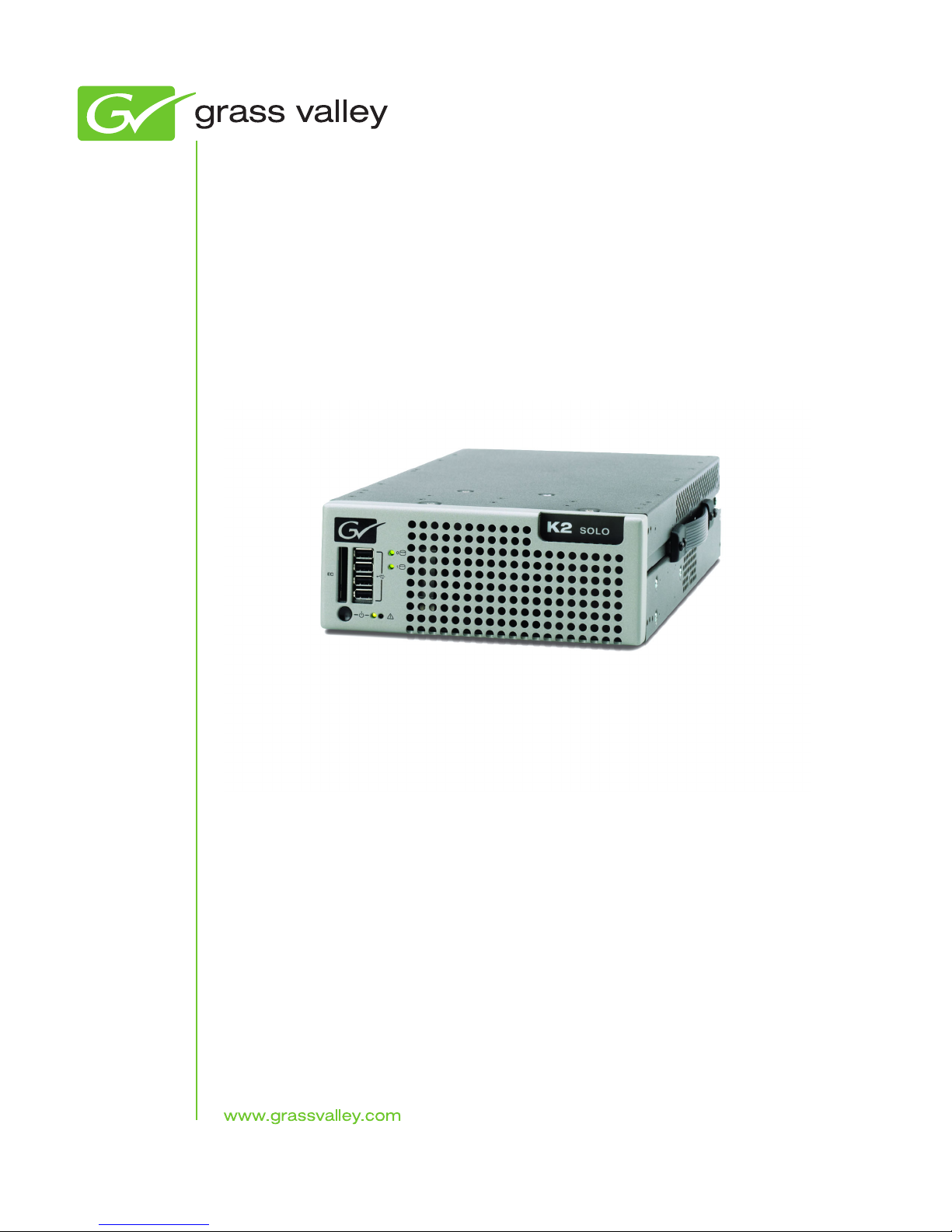
This service manual p rovides procedures f or servicing the K2 ™ Solo™ Media Server
to the field-replaceable unit level. Use this manual to isolate problems to a board or
module, such as the Power Supply, and to make repairs through module exchange.
How this manual is org anized
This manual is organized around the tasks required to service the K2 Solo Media
Server. The following describes the chapters included in this manual:
Chapter 1, Product Description — Describes the key features, system components,
and status indicators of the K2 Solo Media Server.
Chapter 2, System Messages — List s the variou s messages a nd system codes that you
might encounter as you use the K2 Solo Media Server.
Chapter 3, Service Proc edures — Conta ins pr ocedure s for period ic main te nance an d
repair.
Chapter 4, Troubleshoot ing problems — Contains problem de scriptions with steps for
diagnosing and correcting the cause of the problem. Use this information if you are
having trouble with your K2 Solo Media Server.
Chapter 5, Removing and repla ci ng FRUs — Contains procedures f or r emovi ng a nd
replacing field replaceable hardware components.
Getting more information
The following sections help you find the information you need in product manuals
and elsewhere.
For the installer of a K2 Solo Media Server
If you are instal ling a K2 Solo Med ia Ser ver, refer to document ation in t he fol lowing
sequence:
Find this document… I n these locations… In these formats:
1 K2 Release Notes K2 product shipping box Printed
2 Quick Start Guide for the K2 product K2 product shipping box Printed
3 K2 System Guide K2 Documentation CD PDF file
Release Notes
Grass Valley Website PDF file
K2 Documentation CD PDF file
Grass Valley Website PDF file
Grass Valley Website PDF file
The K2 Release Notes contain the latest information about the software shipped on
your system. The release notes include software upgrade instructions, software
specifications and r equir ements, f eature ch ange s from the pr evious relea ses, and any
09 April 2010 K2 Solo Media Server Service Manual 9
Page 10

Finding Information
known problems. Because release notes contain the latest information, they are
printed out and included in the K2 product shipping box, rather than included in the
Documentation CD-ROM. You should always check the Grass Valley Website to
determine if there is an updated version of release notes available.
Documentation CD
Except for the release notes, the full set of support documentation, including this
manual, is available on the K2 Documentation CD that you receive with your K2
product. You can find the Documentation CD packaged in K2 product shipping
boxes.
The Documentation CD includes the following:
•
•
•
K2 AppCenter User Manual — Provides instructions for configuring and operating
the media channels of product.
Quick Start Guides — The Quick Start Guide provides step-by-step installation
instructions for basic installation and operation of the K2 product.
K2 System Guide — Contains the product specifications and instructions for
modifying system settings.
•
Service Manuals — Contains information on servicing and maintaining the K2
product.
•
K2 SAN Installation and Service Manual — Contains installa tion, configura tion, and
maintenance procedures for shared storage options.
•
K2 Storage Cabling Guide — Contains diagrams for cabling the devices of the K2
Solo Media Server.
•
RAID Instruction Manuals — There is an Instruction Manual for each type of RAID
storage device that can be a part of a K2 Solo Media Server. These manual s contain
procedures for configuring and servicing the device.
•
Fibre Channel Switch Installation Manual — Contains information on configuring
and servicing the Fibre Channel switch.
On-line Help Sy st e m s
K2 AppCenter Help — In the AppCenter user interface menu bar select Help, then
choose
SiteConfig Help — In the SiteConfig user interface menu bar select Help, then choose
SiteConfig Help Topics from the drop-down menu.
NetCentral Help — From the NetCentr al int erfa ce sel ect He lp | NetCentral Help Topics.
AppCenter Help Topics from the drop-down menu.
NetCentral documentation
The NetCentral product has its own documentation set, described as follows:
•
NetCentral Quick Star t Guide — Pr ovides an overview o f the i nstalla tion proc ess to
quickly set up and run NetCentral.
•
NetCentral Installation Guide — Identifies requirements and procedures to correctly
10 K2 Solo Media Server Service Manual 09 April 2010
Page 11

set up servers and devices, as well as provides detailed instructions to install and
configure NetCentral software.
•
NetCentral User Guide — Describes how t o use the NetCe ntral Manager to monitor
devices.
•
NetCentral Help — From the NetCentral int erface ac cess on -line hel p. Select Help |
NetCentral Help Topics
.
NetCentral documentation
The NetCentral product has its own documentation set, described as follows:
•
NetCentral Quick Star t Guide — Pr ovides an overview o f the in stallatio n process to
quickly set up and run NetCentral.
•
NetCentral Installation Guide — Identifies r equirements and proced ures to correctly
set up servers and devices, as well as provides detailed instructions to install and
configure NetCentral software.
•
NetCentral User Guide — Describes how t o use the NetCe ntral Manager to monitor
devices.
•
NetCentral Help — From the NetCentral int erface ac cess on -line hel p. Select Help |
NetCentral Help Topics
.
Grass Valley Product Support
Also find information about monitori ng a spec if ic product in that product’s manuals.
Grass Valley Web Site
This public Web site contains all the latest manuals and documentation, and
additional support information. Use the following URL.
http://www.grassvalley.com.
Grass Valley Product Support
To get technical assis tance, check on the statu s of a question, or to re port a new issues,
contact Grass Valley Product Support via e-mail, the Web, or by phone or fax.
Web Technical Support
To access support infor mation on the Web, v isit the pr oduct support Web page on the
Grass Valley Web site. You can download software or find solutions to problems.
World Wide Web:http://www.grassvalley.com/support/
Technical Support E-mail Address:gvgtechsupport@grassvalley.com
Telephone Support
Use the following information to contact Product Support by phone.
09 April 2010 K2 Solo Media Server Service Manual 11
Page 12
Finding Information
International Support Centers
Our international support centers are available 24 hours a day, 7 days a week.
Support Center Toll free In country
France +800 80 80 20 20 +33 1 48 25 20 20
United States +1 800 547 8949 +1 530 478 4148
Authorized Local Support Representative
A local support representa ti ve may be ava il abl e in your count ry. To locate a support
center duri ng normal local business hours, refer t o the followi ng list. This list is
regularly updated on the website for Grass Valley Product Support
(http://www.grassvalley.com/support/contact/phone/)
After–hours local phone support is also available for warranty and contract
customers.
Region County Telephone
Asia China +86 10 5883 7575
Hong Kong, Taiwan, Korea,
Macau
Japan +81 3 6848 5561
Southeast Asia - Malaysia +603 7492 3303
Southeast Asia - Singapore +65 6379 1313
India +91 22 676 10300
Pacific Australia 1 300 721 495
New Zealand 0800 846 676
For callers outside Australia or
New Zealand
Central America, SouthAmerica All +55 11 5509 3440
North America North America, Mexico,
Caribbean
+852 2531 3058
+61 3 8540 3650
+1 800 547 8949;
+1 530 478 4148
12 K2 Solo Media Server Service Manual 09 April 2010
Page 13
Waste Electrical and Electronic Equipment Directive
Region County Telephone
Europe UK, Ireland, Israel +44 118 923 0499
Benelux – Netherlands +31 (0) 35 62 38 421
Benelux – Belgium +32 (0) 2 334 90 30
France +800 80 80 20 20;
+33 1 48 25 20 20
Germany, Austria,
Eastern Europe
Belarus, Russia, Tadzhikistan,
Ukraine, Uzbekistan
Nordics (Norway, Sweden,
Finland, Denmark, Iceland)
Southern Europe – Italy Rome: +39 06 87 20 35 28 ; +39
Southern Europe – Spain +34 91 512 03 50
Switzerland +41 56 299 36 32
Middle East, NearEast, Africa Middle East +971 4 299 64 40
Near East and Africa +800 80 80 20 20;
+49 6150 104 444
+7 095 258 09 20;
+33 (0) 2 334 90 30
+45 40 47 22 37; +32 2 333 00 02
06 8720 35 42. Milan: +39 02 48
41 46 58
+33 1 48 25 20 20
Waste Electrical and Electronic Equipment Directive
09 April 2010 K2 Solo Media Server Service Manual 13
Page 14

Finding Information
14 K2 Solo Media Server Service Manual 09 April 2010
Page 15

Safety Summaries
Read the following sectio ns for important safety information.
• Safety Summary
• Sicherheit – Überblick
• Consignes desécurité
• Certificat ions and compliances
09 April 2010 K2 Solo Media Server Service Manual 15
Page 16
Safety Summaries
Safety Summary
Read and follow the important safety information below, noting especially those
instructions related to risk of fire, electric shock or injury to person s. Addition al
specific warnings not listed here may be found throughout the manual.
Safety terms and symbols
Terms in this manual
Safety-rel ated stateme nts may appear in this manual in the following form:
WARNING: Any instructions i n this manual that re quire opening
the equipment cover or enclosure are for use by qualified service
personnel only. To reduce the risk of electric shock, do not
perform any servicing other than that contained in the operating
instructions unless you are qualified to do so.
WARNING: Warning statements identi fy conditi ons or practices
that may result in personal injury or loss of li fe.
CAUTION: Caution statements identify conditions or practices
that may result in damage to equipment or other property, or
which may cause equipment crucial to your business
environment to become temporarily non-operational.
Terms on the product
These terms may appear on the product:
DANGER — A personal injury hazard is immediately accessible as you read the
marking.
WARNING — A personal injury hazar d exists but is not immediat ely accessible as you
read the marking.
CAUTION — A hazard to property, product, and other equipment is present.
Symbols on the product
The following symbols may appear on the product:
Indicates that dangerous high voltage is present within the
equipment enclosure that may be of sufficient magnitude to
constitute a risk of electric shock.
Indicates that user, operator or service technician should refer to
product manual(s) for important operating, maintenance, or service
instructions.
This is a prompt to n ote fuse rating when rep lacing fuse(s). The fuse
referenced in the text must be replaced with one having the ratings
indicated.
16 K2 Solo Media Server Service Manual 09 April 2010
Page 17

Warnings
The following warning statements identify conditions or practices that can result in
personal injury or loss of life.
Dangerous voltage or current may b e present — Disconnec t power and remove battery
(if applicable) before removing protective panels, soldering, or replacing
components.
Do not service alone — Do not internally service this product unless another person
capable of rendering first aid and resuscitation is present.
Remove jewelry — Prior to servicing, remove jewelry such as rings, watches, and
other metallic objects.
Identifies a prote ctive grounding terminal wh ich must be connected
to earth ground prior to making any other equipment connections.
Identifies an external protec tive gro unding te rminal whi ch may be
connected to earth ground as a supple ment to an internal grounding
terminal.
Indicates that static sensitiv e components are pres ent which may be
damaged by electrostatic discharge. Use anti-static procedures,
equipment and surfaces during servicing.
Avoid exposed circuitry — Do not touch exposed connections, components or
circuitry when power is present.
Use proper power cord — Use only the power cord supplied or specified for this
product.
Ground product — Connect the grounding conductor of the power cord to earth
ground.
Operate only with covers and enclo sure panels in plac e — Do not opera te this pr oduct
when covers or enclosure panels are removed.
Use correct fuse — Use only the fuse typ e and rating specified for t his product.
Use only in dry environment — Do not operate in wet or damp conditions.
Use only in non-explosive environment — Do no t ope rate th is pr oduct in a n explos ive
atmosphere.
High leakage current may be present — Earth connect ion of product is essenti al before
connecting power.
Dual power supplies ma y be present — Be ce rtain to plug each power s upply cord into
a separate bra nch circuit employ ing a separate service ground. Disconnect both power
supply cords prior to servicing.
Double pole neutral fusing — Disconnect mains power prior to servicing.
Use proper lift points — Do not use door latches to lift or move equipment.
Avoid mechanical hazards — Allow all rotating devices to come to a stop before
servicing.
09 April 2010 K2 Solo Media Server Service Manual 17
Page 18

Safety Summaries
Cautions
The following caution statements identify conditions or practices that can result in
damage to equipment or other property
Use correct power source — Do not operate this product from a power source that
applies more than the voltage specified for the product.
Use correct voltage setting — If this product lacks auto-ranging power supplies,
before applying power ensure that the each power supply is set to match the power
source.
Provide proper ventilation — To prevent product overheating, provide equipment
ventilation in accordance with installation instructions.
Use anti-static procedures — Static sensitive components are present which may be
damaged by electrostatic discharge. Use anti-static procedures, equipment and
surfaces during servicing.
Do not operate with suspected equipment failure — If you suspec t pro duct damage or
equipment failure, have the equipment inspected by qualified service personnel.
Ensure mains disconnect — If mains switch is not provided, the power cord(s) of this
equipment provide the means of disconnection. The socket outlet must be installed
near the equipment and must be easily accessible. Verify that all mains power is
disconnected before installing or removing power supplies and/or options.
Route cable properly — Route powe r cords and other cabl es so tha t they ar not likel y
to be damaged. Properly support heavy cable bundles to avoid connector damage.
Use correct power supply co rds — P ower cord s fo r this equipmen t, i f provi ded, me et
all North American electrical codes. Operation of this equipment at voltages
exceeding 130 VAC requires power supply cords which comply with NEMA
configurations. International power cords, if provided, have the approval of the
country of use.
Use correct replacemen t batter y — This pr oduct may conta in bat teri es. To r educe t he
risk of explosion, check polarity and replace only with the same or equivalent type
recommended by manufacturer. Dispose of used batteries according to the
manufacturer’s instructions.
Troubleshoot only to board level — Circuit boards in this product are densely
populated with surfac e mount technology (SMT) components and application specific
integrated circuits (ASICS). As a result, circuit board repair at the component level is
very difficult in the field, if not impossible. For warranty compliance, do not
troubleshoot systems beyond the board level.
18 K2 Solo Media Server Service Manual 09 April 2010
Page 19
Sicherheit – Über bl ick
Lesen und befolgen Sie die wichtigen Sicherheitsinformationen dieses Abschnitts.
Beachten Sie insbesondere die Anweisungen bezüglich
Brand-, Stromschlag- und Verletzungsgefahren. Weitere spezifische, hier nicht
aufgeführte Warnungen finden Sie im gesamten Handbuch.
WARNUNG: Alle Anweisungen in diesem Handbuch, die das
Abnehmen der Geräteabdeckung oder des Gerätegehäuses
erfordern, dürfen nu r von qualifiziertem S ervicepersonal
ausgeführt werden. Um die Stromschlaggefahr zu verringern,
führen Sie keine Wartungsarbeiten außer den in den
Bedienungsanleitungen genann ten Arbeiten aus, es se i denn, Sie
besitzen d ie entsprechende Qualifikationen für diese A rbeiten.
Sicherheit – Begriffe und Symbole
In diesem Handbuch verwendete Begriffe
Sicherheitsrelevante Hinweise können in diesem Handbuch in der folgenden Form
auftauchen:
WARNUNG: Warnungen weisen auf Situationen oder
Vorgehensweisen hin, die Verletzungs- oder Lebensgefahr
bergen.
VORSICHT: Vorsichtshinweise weisen auf Situationen oder
Vorgehensweisen hin, die zu Schäden an
Ausrüstungskomponenten oder an deren Gegenständen oder zum
zeitweisen Ausfall wichtiger Komponenten in der
Arbeitsumgebung führen können.
Hinweise am Produkt
Die folgenden Hinweise können sich am Produkt befinden:
GEFAHR – Wenn Sie diesen Begriff lesen, besteht ein unmittelbares
Verletzungsrisiko.
WARNUNG – Wenn Sie diesen Begriff lesen, besteht ein mittelbares
Verletzungsrisiko.
VORSICHT – Es besteht ein Risiko für Objekte in der Umgebung, den Mixer selbst
oder andere Ausrüstungskomponenten.
Symbole am Produkt
Die folgenden Symbole können sich am Produkt befinden:
Weist auf eine gefährliche Hochspannung im Gerätegehäuse hin,
die stark genug sein kann, um eine Stromsch laggefahr darzustel len.
09 April 2010 K2 Solo Media Server Service Manual 19
Page 20
Safety Summaries
Weist darauf hin, dass der Benutzer, Bediener oder
Servicetechniker wichtige Bedienungs-, Wartungs- oder
Serviceanweisungen in den Produkthandbüchern lesen sollte.
Dies ist eine Aufforderung, beim Wechsel von Sicherungen auf
deren Nennwert zu achten. Die im Text angegebene Sicherung
muss durch eine Sicherung ersetzt werden, die die angegebenen
Nennwerte besitzt.
Weist auf eine Schutzerdungsklemme hin, die mit dem
Erdungskontakt verbunden werden muss, bevor weitere
Ausrüstungskomponenten angeschlossen werden.
Weist auf eine externe Schutzerdungsklemme hin, die als
Ergänzung zu einem internen Erdungskontakt an die Erde
angeschlossen werden kann.
Weist darauf hin, dass es stati sch empfindlic he Komponenten gibt,
die durch eine elektrostatische Entladung beschädigt werden
können. Verwenden Sie ant i sta ti sc he Pr ozeduren, Ausrüstung und
Oberflächen während der Wartung.
Warnungen
Die folgenden Warnungen weisen auf Bedingungen oder Vorgehensweisen hin, die
Verletzungs- oder Lebensgefahr bergen:
Gefährliche Spannungen oder Ströme – Schal ten Sie de n Strom ab, un d entfe rnen Sie
ggf. die Batterie, bevor si e Schut za bdeckungen abnehmen, löten oder Komponente n
austauschen.
Servicearbeiten nicht alleine ausführen – Führen Sie interne Servicearbeiten nur aus,
wenn eine weitere Person anwesend ist, die erste Hilfe leisten und
Wiederbelebungsmaßnahmen einleiten kann.
Schmuck abnehmen – Legen Sie vor Servicearbe iten Schmuck wie Ring e, Uhren und
andere metallische Objekte ab.
Keine offen liegenden Leiter berühren – Berühre n Sie bei eingesc haltete r Stromzuf uhr
keine offen liegenden Leitungen, Komponenten oder Schaltungen.
Richtiges Netzkabel verwenden – Verwenden Sie nur das mitgeliefert e Netzkabel ode r
ein Netzkabel, das den Spezifikationen für dieses Produkt entspricht.
Gerät erden – Schließen Sie den Erdleiter des Netzkabels an den Erdungskontakt an.
Gerät nur mit angebrachten Abdeckungen und Gehä useseiten betreiben – Sc halten Sie
dieses Gerät nicht ein, wenn die Abdeckungen oder Gehäuseseiten entfernt wurden.
Richtige Sicherung verwenden – Verwenden Sie nur Sicherungen, deren Typ und
Nennwert den Spezifikationen für dieses Produkt entsprechen.
Gerät nur in trockener Umgebung verwen den – Betreiben Si e das Gerät nicht in nassen
oder feuchten Umgebungen.
Gerät nur verwenden, wenn keine Explosionsgefahr besteht – Verwenden Sie dieses
Produkt nur in Umgebungen, in denen keinerlei Explosionsgefahr besteht.
20 K2 Solo Media Server Service Manual 09 April 2010
Page 21

Hohe Kriechströme – Das Gerät muss vor dem Ein schalten unbe dingt gee rdet werd en.
Doppelte Spannungsversorgung kann vorhanden sein – Schließen Sie die beide n
Anschlußkabel an getrennte Stromkreise an. Vor Servicearbeiten sind beide
Anschlußkabel vom Netz zu trennen.
Zweipolige, neutrale Sicherung – Schalten Sie den Netzstrom ab, bevor Sie mit den
Servicearbeiten beginnen.
Fassen Sie das Gerät beim Transport richtig an – Halten Sie das Ger ät beim Transpo rt
nicht an Türen oder anderen beweglichen Teilen fest.
Gefahr durch mechanische Teile – Warten Sie, bis der Lüfter vollständig zum Halt
gekommen ist, bevor Sie mit den Servicearbeiten beginnen.
Vorsicht
Die folgenden Vorsichtshinweise weisen auf Bedingungen oder Vorgehensweisen
hin, die zu Schäden an Ausr üstungsko mponente n oder anderen Gegenstände n führen
können:
Gerät nicht öffnen – Durch das unbefugte Öffnen wird die Garantie ungültig.
Richtige Spannungsquelle verwenden – Betreiben Sie das Gerät nicht an einer
Spannungsquelle, die eine höhere Spannung liefert als in den Spezifikationen für
dieses Produkt angegeben.
Gerät ausreichend belüften – Um eine Überhitzung des Geräts zu ve rmeiden , müss en
die Ausrüstungskomponenten entsprechend den Installationsanweisungen belüftet
werden. Legen Sie kein Papier unter das Gerät. Es könnte die Belüftung behindern.
Platzieren Sie das Gerät auf einer ebenen Oberfläche.
Antistatische Vorkehrungen treffen – Es gi bt stati sch empfindl iche Komponenten, d ie
durch eine elektrostatische Entladung beschädigt werden können. Verwenden Sie
antistatische Prozeduren, Ausrüstung und Oberflächen während der Wartung.
CF-Karte nicht mit einem PC verwenden – Die CF-Karte ist speziell formatiert. Die auf
der CF-Karte gespeicherte Software könnte gelöscht werden.
Gerät nicht bei eventuellem Ausrüstungsfehler betreiben – Wenn Sie einen
Produktschaden oder Ausrüstungsfehler vermuten, lassen Sie die Komponente von
einem qualifizierten Servicetechniker untersuchen.
Kabel richtig verlegen – Verlegen Sie Netzkabel und andere Kabel so, dass Sie nicht
beschädigt werden. Stützen Sie schwere Kabelbündel ordnungsgemäß ab, damit die
Anschlüsse nicht beschädigt werden.
Richtige Netzkabel verwenden – Wenn Netzkabel mitgeliefert wurden, er füllen diese
alle nationalen elektri schen Normen. Der Betri eb dieses Geräts mit Spann ungen über
130 V AC erfordert Netzkabel, die NEMA-Konfigurationen entsprechen. Wenn
internationale Netzkabel mitgeliefert wurden, sind diese für das Verwendungsland
zugelassen.
Richtige Ersatzbatterie verwenden – Dieses Gerät enthä lt eine Batter ie. Um die
Explosionsgefahr zu verringern, prüfen Sie di e Polarität und taus chen die Batterie nur
gegen eine Batterie desselben Typs oder eines gleichwertigen, vom Hersteller
empfohlenen Typs aus. Entsorgen Sie gebrauchte Batterien entsprechend den
Anweisungen des Batterieherstellers.
09 April 2010 K2 Solo Media Server Service Manual 21
Page 22

Safety Summaries
Das Gerät enthält keine Teile, die vom Benutzer gewartet werden können. Wenden
Sie sich bei Problemen bitte an den nächsten Händler.
22 K2 Solo Media Server Service Manual 09 April 2010
Page 23
Consignes desécurité
Il est recommandé de lire, de bi en comprendre et s urtout de respe cter les in formations
relatives à la sécurité qui sont exposées ci-après, notamment les consignes destinées
à prévenir les risques d’incendie, les décharges électriques et les blessures aux
personnes. Les avertissements complémentaires, qui ne sont pas nécessairement
repris ci-dessous, mais pré sents da ns toute s les se ctions du manue l, sont éga leme nt à
prendre en considération.
AVERTISSEMENT: Toutes les instructions présentes dans ce
manuel qui concernent l’ouverture des capots ou des logements
de cet équipement sont destinées exclusivement à des membres
qualifiés du personnel de maintenance. Afin de diminuer les
risques de décharges électriques, ne procédez à aucune
intervention d’entre tien autre que celles contenues dans l e
manuel de l’utilisateur, à moins que vous ne soyez habilité pour
le faire.
Consignes et symboles de sécurité
Termes utilisés dans ce manuel
Les consignes de sécurité présentées dans ce manuel peuvent apparaître sous les
formes suivantes :
AVERTISSEMENT: Les avertissements signalent des conditions
ou des pratiques suscepti bles d’occas ionner des bles sures graves,
voire même fatales.
MISE EN GARDE: Les m ises en garde signalent des condi tions
ou des pratiques suscept ibles d’ occasionner un endommagement
à l’équipement ou aux installations, ou de rendre l’équipement
temporairement non opérationnel, ce qui peut por ter pr éjudice à
vos activi tés.
Signalétique apposée sur le produit
La signalétique suivante peut être apposée sur le produit :
DANGER — risque de danger imminent pour l’utilisateur.
AVERTISSEMENT — Risque de danger non imminent pour l’utilisateur.
MISE EN GARDE — Risque d’endommagement du produit, des installations ou des
autres équipements.
Symboles apposés sur le produit
Les symboles suivants peut être apposés sur le produit :
Signale la présence d’une tension élevée et dangereuse dans le
boîtier de l’équipement ; cette tension peut être suffisante pour
constituer un risque de décharge électrique.
09 April 2010 K2 Solo Media Server Service Manual 23
Page 24
Safety Summaries
Signale que l’utilisateur, l’ opérateur ou le technicien de
maintenance doit faire référence au(x) manuel(s) pour prendre
connaissance des instructions d’utilisation, de maintenance ou
d’entretien.
Il s’agit d’une invite à prendre note du calibre du fusible lors du
remplacement de ce dernier. Le fusible auquel il est fait référence
dans le texte doit être remplacé par un fusible du même calibre.
Identifie une borne de protection de mise à la masse qui doit être
raccordée correctement avant de procéder au raccordement des
autres équipements.
I dentifie une borne de protection de mise à la masse qui peut être
connectée en tant que borne de mise à la masse supplémentaire.
Signale la présence de compo sants sensi bles à l’él ectrici té stati que
et qui sont susceptibles d’être endommagés par une décharge
électrostatique. Utilisez des procédures, des équipements et des
surfaces antistatiques durant les interventions d’entretien.
Avertissements
Les avertissements suivants signalent des conditions ou des pratiques susceptibles
d’occasionner des blessures graves, voire même fatales :
Présence possible de tensions ou de courants dangereux — Mettez hors tension,
débranchez et retirez la pile (le cas échéant) avant de déposer les couvercles de
protection, de défaire une soudure ou de remplacer des composants.
Ne procédez pas seul à un e intervention d’entre tien — Ne réalisez pas une intervention
d’entretien interne sur ce produit si une personne n’est pas présente pour fournir les
premiers soins en cas d’accident.
Retirez tous vos bijoux — Avant de procéder à une intervention d’entretien, retirez
tous vos bijoux, notamment les bagues, la montre ou tout autre objet métallique.
Évitez tout contact avec les circuits exposés — Évitez tout contact avec les
connexions, les composants ou les circuits exposés s’ils sont sous tension.
Utilisez le cordon d’alimentation approprié — Utilisez exclu sivement le cordon
d’alimentation fourni avec ce produit ou spécifié pour ce produit.
Raccordez le produit à la masse — Raccordez le conducteur de masse du cordon
d’alimentation à la borne de masse de la prise secteur.
Utilisez le produit lorsque les couvercles et les capots sont en place — N’utilisez pas
ce produit si les couvercles et les capots sont déposés.
Utilisez le bon fusible — Utilisez exclusivement un fusible du type et du calibre
spécifiés pour ce produit.
Utilisez ce produit exclusivement dans un environnement sec — N’utilise z pas ce
produit dans un environnement humide.
Utilisez ce produit exclu siv eme nt dans un environnement non ex plos ible — N’utilisez
pas ce produit dans un environnement dont l’atmosphère est explosible.
24 K2 Solo Media Server Service Manual 09 April 2010
Page 25

Présence possible de courants de fuite — Un raccordement à la masse est
indispensable avant la mise sous tension.
Deux alimentations peuvent être présentes dans l’équipement — Assurez vous que
chaque cordon d’alimen tation est raccordé à des circuits de ter re séparés. Débranc hez
les deux cordons d’alimentation avant toute intervention.
Fusion neutre bipolaire — Débranchez l’alimentation principale avant de procéder à
une intervention d’entretien.
Utilisez les points de levage appro priés — Ne p as u ti li ser les verrous de la port e po ur
lever ou déplacer l’équipement.
Évitez les dangers méca nique s — Laissez le ventilateu r s ’ar rêter avant de procéde r à
une intervention d’entretien.
Mises en garde
Les mises en garde suivantes signalent les conditions et les pratiques susceptibles
d’occasionner des endommagements à l’équipement et aux installations :
N’ouvrez pas l’appareil — Toute ouverture prohibée de l’appareil aura pour effet
d’annuler la garantie.
Utilisez la source d’alimenta tion adéqu ate — Ne bra nchez pa s ce pr oduit à une so urce
d’alimentation qui utilis e une tensi on supérieu re à la tens ion nomin ale spéci fiée pour
ce produit.
Assurez une ventilation adéquate — Pour éviter toute surchauffe du produit, assurez
une ventilation de l’équipement conformément aux instructions d’installation. Ne
déposez aucun document sous l’appareil – ils peuvent gêner la ventilation. Placez
l’appareil sur une surf ace plane.
Utilisez des procédures antis tatiques - Les composants sensi bles à l’électrici té statique
présents dans l’équipement sont susceptibles d’être endommagés par une décharge
électrostatiq ue. Utilisez des pr océdures, des équi pements et des surf aces antistat iques
durant les interventions d’entretien.
N’utilisez pas la carte CF avec un PC — La carte CF a été spécialement formatée. Le
logiciel enregistré sur la carte CF risque d’être effacé.
N’utilisez pas l’équipemen t si un dysfonction nement est susp ecté — Si vo us suspectez
un dysfonctionnement du pr oduit, fai tes inspec ter cel ui-ci par un membre qualif ié du
personnel d’entretien.
Acheminez les câbles correctement — Acheminez les câbles d’alimentation et les
autres câbles de manière à ce qu’ils ne risquent pas d’être endommagés. Supportez
correctement les enroul ements de câbles afin de ne pas endomma ger les connecteur s.
Utilisez les cordons d’alimentation adéquats — Les cordons d’alimentation de cet
équipement, s’ils sont fournis, satisfont aux exigences de toutes les réglementations
régionales. L’util isat ion de cet é quipement à des tens ions dé passa nt les 130 V e n c. a.
requiert des cordons d’alimentation qui satisfont aux exigences des configurations
NEMA. Les cordons internationa ux, s’ils sont four nis, ont reçu l’approba tion du pays
dans lequel l’équipement est utilisé.
09 April 2010 K2 Solo Media Server Service Manual 25
Page 26

Safety Summaries
Utilisez une pile de remplacement adéquate — Ce produit renferme une pile. Pour
réduire le risque d’explosion, vérifiez la polarité et ne remplacez la pile que par une
pile du même type, recommandée par le fabricant. Mettez les piles usagées au rebut
conformément aux instructions du fabricant des piles.
Cette unité ne contient aucune partie qui peut faire l’objet d’un entretien par
l’utilisateur. Si un problème survient, veuillez contacter votre distributeur local.
26 K2 Solo Media Server Service Manual 09 April 2010
Page 27

Certifications and compliances
Canadian certified power cords
Canadian approval includes the products and power cords appropriate for use in the
North America power network. All other power cords supplied are approved for the
country of use.
FCC emission control
This equipment has been tested and found to comply with the limits for a Class A
digital device, pursuant to Part 15 of the FCC Rules. These limits are designed to
provide reasonable protection against harmful interference when the equipment is
operated in a commercial environment. This equipment generates, uses, and can
radiate radio frequency energy and, if not installed and used in accordance with the
instruction manual, may cause harmful interference to radio communications.
Operation of this equipment in a residential area is likely to cause harmful
interference in which case the user will be required to correct the interference at his
own expense. Changes or modifica tions not expr essly a pproved by Grass Val ley can
affect emission compliance and could void the user’s authority to operate this
equipment.
Canadian EMC Notice of Compliance
This digital apparatus does not exceed the Class A limits for radio noise emissions
from digital apparatus set out in the Radio Interference Regulations of the Canadian
Department of Communications.
Le présent appareil numérique n’émet pas de bruits radioélectriques dépassant les
limites applicables aux appareils numériques de la classe A préscrites dans le
Règlement sur le brouillage radioélectrique édicté par le ministère des
Communications du Canada.
EN55103 1/2 Class A warning
This product has been evaluated for Electromagnetic Compatibility under the EN
55103-1/2 standards f or Emissions and Immunity and meets the requi rements for E4
environment.
This product complies wit h Class A (E4 environment). In a do mestic environment this
product may cause radio interference in which case the user may be required to take
adequate measures.
FCC emission limits
This device complies with Part 15 of the FCC Rules. Operation is subject to the
following two conditions : (1) This device may not cau se harmful interference , and (2)
this device must accept any interference received, inclu ding interference that may
cause undesirable operation.
09 April 2010 K2 Solo Media Server Service Manual 27
Page 28

Safety Summaries
Laser compliance
Laser safety requirements
Laser safety
This product may contain a Class 1 certified laser device. Operating this product
outside specifi cations or alte ring it s origin al des ign may res ult in hazardous radia tion
exposure, and may be cons idered an act of mod ifying or new manufact uring of a laser
product under U.S. regulations contained in 21CFR Chapter 1, subchapter J or
CENELEC regulations in HD 482 S1. People perfo rming s uch an a ct ar e req uired by
law to recertify and reidentify this product in accordance with provisions of 21CFR
subchapter J for distribution within the U.S.A., and in accordance with CENELEC
HD 482 S1 for distribution within countries using the IEC 825 standard.
Laser safety in the United States is regulated by the Center for Devices and
Radiological Health (CDRH). The laser saf ety regulations are published i n the “Laser
Product Performance Standard,” Code of Federal Regulation (CFR), Title 21,
Subchapter J.
The International Electrotechnical Commission (IEC) Standard 825, “Radiation of
Laser Products, Equipme nt Classifi cation, Requi rements and User’s Guide,” governs
laser products o utside the United States . Europe and member nations of the European
Free Trade Association fall under the jurisdiction of the Comité Européen de
Normalization Electrotechnique (CENELEC).
Safety certification
This product has been evaluated and meets the following Safety Certification
Standards:
Standard Designed/tested for compliance with:
ANSI/UL 60950-1 Safety of Informatio n Technology Equipment,
IEC 60950-1 with CB
cert.
CAN/CSA C22.2 No.
60950-1
BS EN 60950-1 Safety of I nformation Technology Eq uipment,
including Electrical Business Equipment
(Second edition 2007).
Safety of Information Technology Equipment,
including Electrical Business Equipment
(Second edition, 2005).
Safety of Information Technology Equipment,
including Electrical Business Equipment
(Second edition 2007).
including Electrical Business Equipment
2006.
28 K2 Solo Media Server Service Manual 09 April 2010
Page 29

Chapter 1
Product Description
Topics in this section include the following:
•“Overview description” on page 30
•“K2 Solo Media Server orientation” on page 30
•“FRU functional descriptions” on page 31
•“System Overview” on page 34
•“Status indicators” on page 35
09 April 2010 K2 Solo Media Server Service Manual 29
Page 30
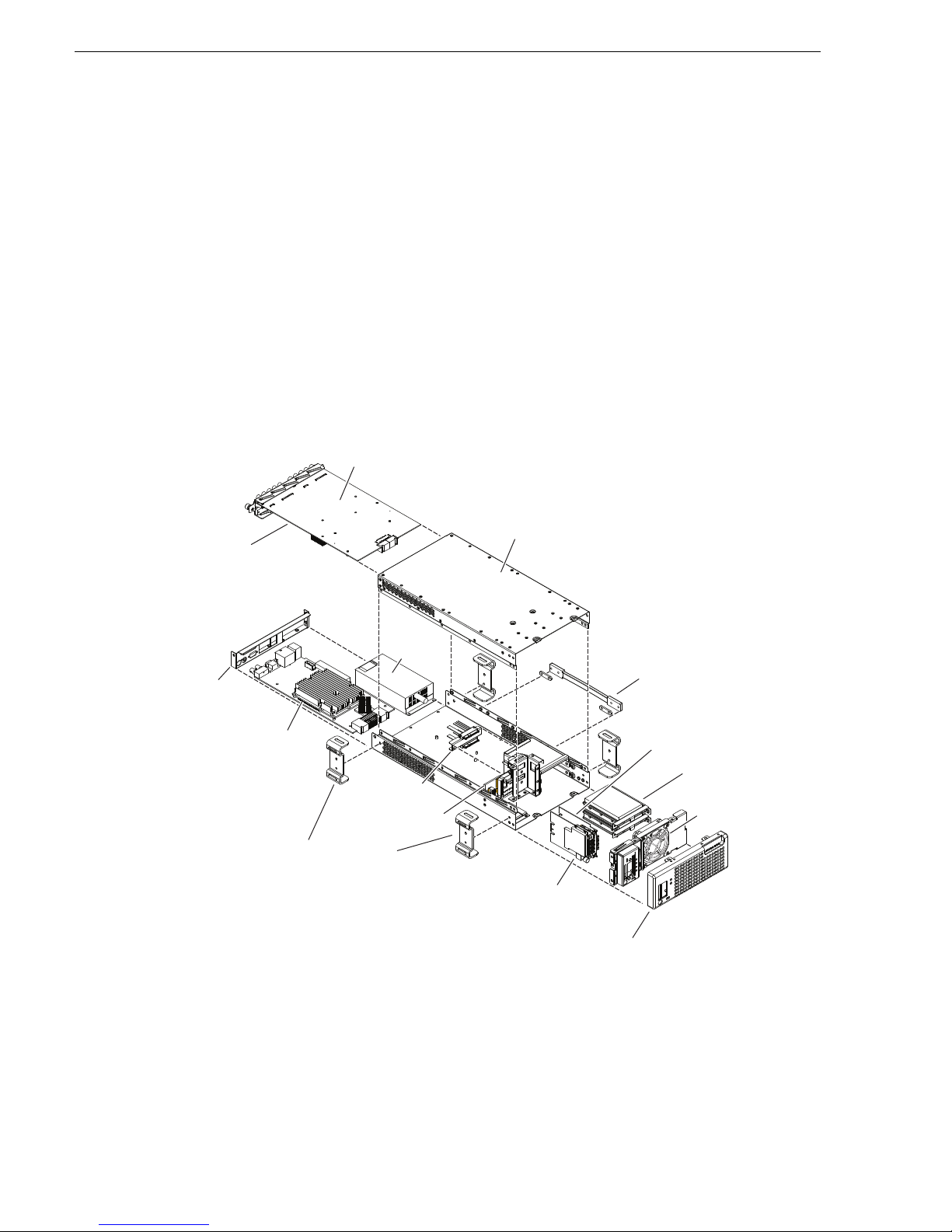
Chapter 1 Product Description
Disk modules
Optional
Handipak handle
Disk controller board
with CF boot media
Chassis fan
Front bezel
Front interconnect board
Optional Handipak feet (4)
Drive cable
assembly
Midplane
Codec module
Top cover
Optional
MPEG-2 encoder
cards or AVC-Intra
codec cards
(attached to underside
of codec module)
Power
supply
module
Carrier module
Rear panel
Overview description
The K2 Solo Media Server is a cost-ef fective media platfor m that incorporate s IT and
storage technologies to del iv er a networked solution to facilit i es for replay in sports,
news, live, and live-to-tape applications, as well as ingest, playout, and media asset
management. It is a comprehe nsive platform that pro vides a suite of user appl ications,
system tools, and the largest range of third party interactivity in the industry.
Refer to the K2 System Guide for other high-level descriptions of features, controls,
applications, and subsystems.
K2 Solo Media Server orie ntation
The following illu strat ion sh ows t he loca tion o f Fiel d Replac eab le Unit s (FRUs) a nd
other components in the K2 Solo Media Server.
30 K2 Solo Media Server Service Manual 09 April 2010
Page 31

FRU functional descriptions
The Field Replaceable Units (FRUs) described in this section are as follows:
• “Chassis fan”
• “Disk modules”
• “CompactFlash boot media”
• “Power supply module”
• “Codec module”
• “MPEG-2 enc oder card”
• “AVC-Intra codec card”
• “Disk contro ller board”
• “Front interconnect board”
• “Midplane board”
• “Carrier module”
FRU functional descriptions
For procedures, refer to Chapter 5, Removing and replaci ng FRUs.
Chassis fan
The chassis fan is mounted in the fan bracket. It provides cooling to the unit. It is
mounted in the front of the unit, behind the front bezel.
Refer to “Fan assembly removal” on page 92 for procedures.
Disk modules
There are 2 slots for disk modules in the K2 Solo Media Server. The slots are located
behind the front be zel as sembly in the front o f t he c hassis. Each slot can con tai n one
disk module, and each module contains one hard drive. A K2 Solo Media Server
contains 2 disk modules. Disk modules plug into the drive cable assembly.
Data is written or “str iped” acr oss the disks in a cont inuous fa shion, whic h makes the
disks a “stripe group”. This stripe group appears as the V: drive to the Windows
operating system. The V: drive stores media. It also stores media file system,
database, and configuration information.
Disks are configured as RAID 0, so you can not remove and replace a disk module
while the K2 Solo Media Server is operational. If a disk fail s, you lose al l media.
Refer to “Disk controller board removal” on page 93 for procedures.
CompactFlash boot media
The CompactFlash boot media contains the system drive, also known as the C: drive.
The C: drive contains application and operating system files. The CompactFlash
media is hosted by the disk controller board.
Refer to “CompactFlash boot media removal” on page 91 for procedures.
09 April 2010 K2 Solo Media Server Service Manual 31
Page 32

Chapter 1 Product Description
Power supply module
The K2 Solo Media Server has one power supply. You can not remove and replace
the power supply while the K2 Solo Media Server is operational. The power supply
has a fan with automatic speed control. The power supply has protection for over
voltage, over current, and short circuits.
Refer to “Power supply removal” on page 99 for proced ures.
Codec module
The K2 Solo Media Server has one codec modul e. The codec module hosts two media
input/output channels. The codec module is oriented horizontally across the rear of
the K2 Solo Media Server chassis. It p r ovides the majority of the K2 Solo Medi a
Server’s media-related input and output connectors on the rear panel. The codec
module plugs into the midplane board.
A codec module can host a pa ir of codec option c ards. It is not al lowed to have a codec
module host just one codec opt ion card. There are two t ypes of codec opti on cards, as
follows:
• MPEG-2 encoder card
• AVC-Intra codec card
A codec module that host s codec opti on cards must have either two MPEG-2 encoder
cards or two AVC-Intra codec cards. It is not allowed to have one MPEG-2 encoder
card and one AVC-Intra codec card on the same codec module.
Check K2 Release Notes for support of MPEG-2 and AVC-Intra.
Refer to “Unfasten and disconnect cables” on page 97 for procedures.
MPEG-2 encoder card
A pair of MPEG-2 encoder cards is a codec modu le option. A codec modul e can host
two MPEG-2 encoder cards, one for each of the codec module’s channels. An
MPEG-2 encoder card provides MPEG-2 encode functiona lity to a channel . MPEG-2
decode functionality is a standard feature and does not require a dedicated card.
Refer to “Codec option card removal” on page 90 for procedures.
AVC-Intra codec card
A pair of AVC-Intra co dec ca rds i s a cod ec modul e opti on. A codec module c an host
two AVC-Intra codec cards, one for each of the codec module’s channels. An
AVC-Intra codec card provides AVC-Intra encode and decode functionality to a
channel.
Refer to “Codec option card removal” on page 90 for procedures.
32 K2 Solo Media Server Service Manual 09 April 2010
Page 33

Disk controller board
The disk controller board provides the RAID functionality for the internal disks and
reports the status of the chassis fans. It contro ls status LEDs and the front bezel Power
and Service LEDs. It hosts the CompactFlash boot media. It is mounted in the front
of the unit and plugs into the midplane board.
Refer to “Disk controller board removal” on page 93 for procedures.
Front interconnect board
The front interconnect board provides front interface functionality. It hosts the front
USB ports, the Express Ca rd, and the stan dby switch. It is mou nted in t he front of the
unit and plugs into the midplane board.
Refer to “Front interconnect board removal” on page 93 for procedures.
Midplane board
The midplane board provides connections for the rear modules. The disk controller
board and the front interconnect board also plug into the midplane board. It is
mounted in the center of the unit.
Disk controller board
Refer to “Midplane board removal” on page 101 for procedures.
Carrier module
The carrier module provides the fu nctionality typica lly associated with a motherboard
in a PC. It hosts the CPU and provides rear panel connections for Gigabit Ethernet,
USB, VGA, and IEEE 1394a (Firewire). The IEEE 1394a port is for debugging
purposes only. It is not supported for customer use. Do not attempt to configure or
otherwise use this port. The carrier module also provides a GPI connection and
connections for reference.
Refer to “Carrier module removal” on page 99 for procedures.
Drive cable assembly
The drive cable assembly includes the disk cables and a bracket for mounting drive
connectors in the chassis.
Refer to “Drive cable assembly removal” on page 101 for procedures.
09 April 2010 K2 Solo Media Server Service Manual 33
Page 34

Chapter 1 Product Description
CPU module
Codec
Board
Midplane
Power Supply
VGA Monitor
USB Mouse
USB Keyboard
Dual GigE Ports
Inputs and
Outputs:
Audio,
Video,
Timecode,
RS-422
Dual GigE Ports
Four
USB
Ports
Express
card
GPIO
Reference
Standby
switch
Application
System
System
Resources
Real
Time
System
Disk
Controller
Front
Connect
Disk Modules
Fans
Compact
Flash
Fan Status
PCIe SATA
USB
SM
BUS
PCIe Switch
Optional
MPEG-2 card
Optional
MPEG-2 card
System Overview
The K2 Solo Media Server is a PCIe bus-based Windows computer with extensive
enhancements to pr ovide the video disk r ecorder functionali ty. This section expl ain s
the major ar chitectural blocks.
34 K2 Solo Media Server Service Manual 09 April 2010
Page 35

Status indicators
D
!
The following sections describe the visual and audible indicators that communicate
the current operating status and system health of the K2 Solo Media Server.
Front panel indicators
The following indicators are visible from the front panel view.
isk Module
LEDs
Status indicators
Power LED
The Power LED indicates status as follows::
LED behavior Status Condition
Off The standby switch is set to Off and the K2 Solo Media Server is not
Green steady on The standby switch is set to On and the K2 Solo Media Server is either in the
Service LED
The following table explains the status conditions indicated by the different Service
LED behaviors. If two or more status conditions occur simultaneously, the LED
displays the behavior for the highest priority condition.
LED behavior Status Condition Priority
Flashing pattern alternating
Yellow/Green/Red/Off twice a
second
Solid Red Global failure — The K2 Solo Media Server system
Solid Yellow Warning — The K2 Solo Media Server system
Standby
switch
Power
Service
LED
operational.
startup process or has competed the startup process and is operational.
LED
WARNING: The power standby switch does not turn off power to the
system. To turn power off both power supplies must be disconnected
from the pow er source.
Identify — The K2 Solo Media Server is being
directed to identify itsel f by NetCe ntral o r some o ther
application.
software has detected a critical error or failure that
impacts record/play operations.
software has detected a problem that requires attention
but does not immediately impact record/play
operations.
1
2
3
09 April 2010 K2 Solo Media Server Service Manual 35
Page 36

Chapter 1 Product Description
SDI IN1 SDI OUT1 SDI OUT2
LTC I/O
AES AUDIO RS422
SDI OUT1 SDI OUT2
AES AUDIO RS422
LTC I/O
SDI IN2 SDI IN3 SDI IN1 SDI IN2 SDI IN3
RTP RTP
LED behavior Status Condition Priority
Flashing Yellow pattern three
times a second.
Drive failure — An internal RAID drive has failed. 4
Flashing pattern alternating
Yellow/Green once a second.
Off Normal — The K2 Solo Media Server is healthy and
Disk module LEDs
Each disk module has an LED that indic ates status. The LEDs are lo cated on the front
bezel. The following table explains the status conditions indicated by the different
LED behaviors. If two or more stat us conditions occur simultaneously, the LED
displays the behavior for the highest priority condition. Priority number 1 is the
highest priority
LED behavior Status Condition Priority
Amber flashing pattern. Identify — The drive is being directed to identify itself
Green flashing pattern twice a
second.
Red ON solid. Fault — The RAID controller has marked th e drive as
Amber ON solid. Offline — The drive is unbound. 3
Green flashing patter n ten times a
second.
Drive rebuild — An internal RAID dri ve is rebuilding. 5
operating normally.
by Storage Utility or some other application.
Rebuild — The RAI D controller has marked the dri ve
as rebuilding.
faulty.
Normal drive activity — The drive is heal thy and disk
access is underway.
5
1
3
3
3
Green ON solid Normal drive activity — The drive is healthy and no
OFF No drive — Drive is not present or is not fully e ngaged
Rear panel indicators
The following indicators report status from the rear panel view.
Codec board indicator
Each channel has a green/r ed LED that indicates t he status of the Real Time Proc essor
(RTP).
3
disk access is currently underway.
—
in slot.
36 K2 Solo Media Server Service Manual 09 April 2010
Page 37

Interpret the RTP LED as follows:
e
G
LED behavior Status condition
Green flashing at
approximately 1
second intervals
Green flashing at
greater than 1 second
intervals
Red RTP error condition. Real Time OS is not runn ing.
Off Real Time OS is not running.
RTP is up and connected to the host
RTP is not connected to the host.
LAN connector indicator codes
The motherboard has four RJ- 45 LAN connectors that include int egrated status LEDs.
The LEDs are oriented as follows:
Rear panel indicators
The meanings of the LED states are described in the following table:
LED LED state Status Condition
Green Green On The adapter is connected to a valid link partner
Green/Yellow/
Orange
If a LAN connector is faulty, you must replace the carrier module.
Power supply indicators
An indicator of power supply operation is the audible fan noise.
The Service LED on the front of the K2 Solo Media Server also indicates power
supply status. Refer to “Service LED” on page 35.
reen
Green flashing Da ta activity
Off No link
Off 10 Mbps
Green 100 Mbps
Yellow 10000 Mbps
Orange flashing Identify
Green/Yellow/Orang
If the power source and the power cord are OK yet there is still a power supply
problem, refer to “Power supply problems” on page 78.
09 April 2010 K2 Solo Media Server Service Manual 37
Page 38

Chapter 1 Product Description
GPI
VGA REF. LOOP THROUGH
Reference
Reference indicator
There is a small hole in the carrier module next to the “REF. LOOP THROUGH”
BNC connectors.
Through this hole a LED is visible. When the LED is lit, the reference signal is present
and locked.
System beep codes
When you start up the K2 Solo Media Server by pressing the standby switch or by
doing a Windows operating system restart, the CPU module might emit two short
beeps. Otherwise, if there are no errors present, the K2 Solo Media Server does not
emit any audible beeps.
When an error occurs during Power On Self Test (POST), the BIOS displays a POST
code that describes the problem. The BIOS might also issue one or more beeps to
signal the problem. This indicates a serious error and it is likely that the carrier module
must be replaced. Contact Grass Valley Support.
38 K2 Solo Media Server Service Manual 09 April 2010
Page 39

Chapter 2
System Messages
Topics in this section include the following:
• “About system messages” on page 40
• “Critical system startup messages” on page 41
• “Viewing A ppCenter system status messages” on page 41
09 April 2010 K2 Solo Media Server Service Manual 39
Page 40

Chapter 2 System Messages
About system me ss a ges
The following messages are displayed to indicate K2 Solo Media Server status:
• Normal BIOS messages — These mess ages can be observed on a locall y connected
VGA monitor during normal startup processes
• BIOS POST error messages — If there is a problem these messag es are displayed
on a locally connected VGA monito r. Durin g the Powe r On Self Test (P OST), t he
BIOS checks for problems and displays these messages.
• K2 Solo Media Server startup messages — As AppCenter opens the K2 Solo
Media Server determines if system health is adequate by checking critical
subsystems. A dialog box is displayed that indicates progress and displays
messages. Refer to “Critical system startup messages” on page 41.
• Status bar and StatusPane messages — During normal operation AppCenter
displays system status mess ages on the status bar. From the stat us bar you can open
the StatusPane to see both current and previous messages. You can observe these
messages in AppCenter on a locally connected VGA monitor or on a network
connected control point PC. Refer to “Viewing AppCenter system status
messages” on page 41.
• Storage Utility mess age s — Whil e y ou are using Storage Util it y, pop-up message
boxes inform you of the current status of the storage system.
• NetCentral messages — If you are monitoring the K2 Solo Media Server with
NetCentral, the NetCent ral interface displa ys a variety of messages an d other status
indicators. Refer to the NetCentral Help menu for a complete list of all the
messages that a monitored device can send.
40 K2 Solo Media Server Service Manual 09 April 2010
Page 41

Critical system startup messages
The following messages appear in the AppCenter system startup message box as
critical subsystems are checked during K2 Solo Media Server startup processes. If a
critical failure is detected, the K2 Solo Media Server is rendered inoperable and the
failure me ssage appears.
Critical subsystem check messages Failure messages
System Startup Startup error
Missing or bad hardware
A real time processor is not functioning correctly
Checking hardware… Hardware fault
Checking media disks… One or more media disks fai led to initiali ze
Missing or bad hardware
Missing or bad database
Checking file system… No file system is running
Checking database… Database fault
Critical system startup messages
Checking real-time system status… A real-time system failed to initialize
Updating configuration… Failed to synchronize configurations
Starting services… Unable to communicate with <servi ce name>
Viewing AppCenter system status messages
System status messages are displayed in the AppCenter status bar. There are two types
of system status messages, as follows:
• Channel status mes sages — I n normal op eration, this ty pe of messa ge disp lays the
current operating status of the selected channel.
• System error messages — If a problem develops with the system software or a
hardware subsystem, this type of message is displayed for approximately 5
seconds. Afterward, t he display ret urns to the chan nel statu s message and the er ror
message is written to the st atus log file. When a message is wri tten to the status log,
a Status Icon indicates the severity of the message.
09 April 2010 K2 Solo Media Server Service Manual 41
Page 42

Chapter 2 System Messages
Status Messages
Protocol
Monitor
Button
Transfer
Monitor
Button
StatusPane
Button
Player 2: Playing 'List_10', 'Section 1', 'Clip_2'
Viewing system status messages
System status messages appear in the AppCenter status bar, which is located across
the bottom of the AppCenter window, and consists of a message area, several tool
buttons, and a status icon. The button icons appear only when the related function is
active. In the position of the StatusPane button, status icons appear.
The status icon changes depending on the status of the current status message.
Icon Name Description
Information A recent information message is present.
Warning There is at least one warning message, and no alert messages.
Alert There is at least one uncleared alert message.
Current and previous system status messages can be viewed in the StatusPane. To
open the StatusPane, click
Help | System Status.
42 K2 Solo Media Server Service Manual 09 April 2010
Page 43

Copying StatusPane messages to the clip board
Status icon
Date Time The machine that
reports this message
The subsystem that
reports this message
The StatusPane is used to view detailed system messages including status, warning,
and error messages. S ystem stat us messages p rovide status icon s and a de scription o f
the status event reported by the message. If there is a problem, a corrective action is
indicated. Use these messages along with Chapter 4, Troubleshooting problems to
determine if a service procedure is necessary.
If you have a remote AppCenter Channel Suite with channels from multiple K2
systems, the messages from the different machines are combined in the StatusPane
that you view from the Channel Suite. To help you determine which machine is
generating a message, each message lists the machine name.
Copying StatusPane messages to the clip board
1. Select the message or messages in the StatusPane.
2. Click
After copying the message, it can be pasted using standard Windows techniques.
Clearing messages
Clearing messages from th e StatusPa ne remo ves them fr om the logging da tabase and
the StatusPane. Th is also clear s the state of the subsyste m indicators so they no lon ger
display the alert and warning symbols.
1. Open the StatusPane, then click
Copy.
Clear.
2. When a message prompts you to confirm, click
All messages are removed from the StatusPane and logging database.
09 April 2010 K2 Solo Media Server Service Manual 43
Yes.
Page 44

Chapter 2 System Messages
44 K2 Solo Media Server Service Manual 09 April 2010
Page 45

Chapter 3
Service Procedures
Topics in this section include the following:
•“About the write filter” on page 45
•“Enabling the write filter” on page 45
•“Disabling the write filter” on page 46
•“Committing a file to di sk with write filter enabled” on page 46
•“Exporting log files” on page 47
•“Replacing a RAID 0 drive” on page 49
•“About networking” on page 49
•“Restoring network configuration” on page 50
•“Checking services” on page 60
•“Checking pre-installed software” on page 61
•“Making CMOS settings” on page 62
•“Using recovery images” on page 62
•“Using diagnostic tools” on page 67
About the write filter
The K2 Solo Media Server has a file-base d write filter , which is a feature of the
Windows embedded operating system. With the write filter enabled, files can be
created, modified, an d de leted, but these cha nges a re hel d i n a memory cache. When
the K2 Solo Media Server restarts, these changes are lost and the K 2 Solo Media
Server returns to its original state. This protects the K2 Solo Media Serve r from
changes and increases on-air reliability. For any system configuration change the
write filter must be dis abled otherwise chang es are lost at the next restart.
Some directories, such as C:\logs, C:\Profile\config, and C:\Profile\ChannelSuites,
are excluded from write filter protection, so that channel configuration and logs are
saved. Do not attempt to alt er this list of excluded di rectories. If you suspe ct that write
filter configuration has been alter ed, use the recovery i ma ge p rocess to restore to the
default configuration.
To enable the write filter, the K2 Solo Media Server must be restarted. Likewise, to
disable the write filter, the K2 Solo Media Server must be restarted. You can enable/
disable the write filter remotely using the SiteConfig lock/unlock feature on one K2
Solo Media Server a t a t ime or on a group o f K2 Solo Med ia Server s all a t once. You
can also enable/disab le the write filter from a local K2 Solo Media Server.
Enabling the write filter
Prerequisite:
09 April 2010 K2 Solo Media Server Service Manual 45
Page 46

Chapter 3 Service Procedures
• K2 software must be installed on the K2 S olo Media Server.
1. If you have not already done so, log on to the K2 Solo Media Server with
administrator privileges.
2. From the Windows desktop click
Utility
.
FBWF Manager opens.
3. Under Filter Settings, set Filter to
4. Under Protected Volumes, set C: to
5. Click
OK.
6. When prompted, restart the K2 Solo Media Server.
Disabling the write filter
Prerequisite:
• K2 software must be installed on the K2 S olo Media Server.
1. If you have not already done so, log on to the K2 Solo Media Server with
administrator privileges.
2. From the Windows desktop click
Utility
.
FBWF Manager opens.
3. Under Filter Settings, set Filter to
4. Click
OK.
Start | All Programs | Grass Valley | Write Filter
Enable.
Protected.
Start | All Programs | Grass Valley | Write Filter
Disable.
5. When prompted, restart the K2 Solo Media Server.
Committing a file to disk with write filter enabled
Prerequisite:
• K2 software must be installed on the K2 S olo Media Server.
You can over-ride the write filter for an individual file and permanently save the file
to disk.
1. If you have not already done so, log on to the K2 Solo Media Server with
administrator privileges.
2. From the Windows desktop click
Utility
.
FBWF Manager opens.
3. Under Exclusions, click
Browse.
4. Browse to the file that you want to save permanently, select the file and click
Files in directories that exist on the CompactFlash can be created. New directories
cannot be created. You cannot commit deletions of files.
Start | All Programs | Grass Valley | Write Filter
OK.
46 K2 Solo Media Server Service Manual 09 April 2010
Page 47

5. Click Commit.
Exporting log files
6. Click
OK.
Exporting log files
The procedures in this section describe how to export log files from the K2 Solo
Media Server. The log files can include the following:
• All applications messages
• The Windows Event Log
• Logs from the media database
• Dr. Watson messages.
The exported log files are combined in a ZIP file. The ZIP file can be sent to Grass
Valley product support whe re the y can analyze the logs to det ermi ne t he operational
status of your K2 Solo Media Server.
NOTE: ExportLog does not export StatusPane messages. To capture StatusPane
messages, refer to the “Copying StatusPane messages to the clip bo ard” on page 43.
When you export the log zip file, you must either export it to a location that is not
protected by the K2 Solo Media Server write filter, or else disable the write filter
before exporting.
Use one of the following procedures to export the logs.
Exporting log files from AppCenter workstation
1. In AppCenter workstation click
System | Export Log. The Export Log dialog box
opens.
2. Click the
Logs tab.
09 April 2010 K2 Solo Media Server Service Manual 47
Page 48

Chapter 3 Service Procedures
3. Select the logs to export.
4. Click the
Destination tab.
5. Browse to a location for saving the log file.
6. Name the log file.
7. Click
Export. A progress bar appears.
8. When the export process is complete, and message confirms success. Click
close the Export Log dialog box to continue.
9. Find the log file at the specified location.
10.If you disabled the write filter, enable it before continuing.
Exporting log files using the Windows command line
This procedure allows you to export log files even if AppCenter does not start
properly. It uses the Windows command prompt.
1. If you have not already done so, connect a mouse and keyboard to the K2 client
system.
2. In the Windows task bar, select
Start | Run.
3. Type the following in the Run dialog box, then click
c:\profile\exportlog
The ExportLog dialog box is displayed.
4. Continue with the procedure “Export ing log files from Ap pCenter workstation” on
page 47, starting with step 2.
OK and
OK.
48 K2 Solo Media Server Service Manual 09 April 2010
Page 49

Replacing a RAID 0 drive
A K2 Solo Media Server’s disk module s are configured as RAID 0, so when one drive
fails, all media is lost. To replace a RAID 0 drive, do the following:
1. If you have not already done so, disable the write filter.
2. Unbind the LUN that has the failed drive.
3. Remove the failed drive from the K2 Solo Media Server chassis.
4. Insert the replacement drive in the K2 Solo Media Server chassis.
5. Restart the K2 Solo Media Server.
6. Using Storage Utility on the K2 Solo Media Server, bind disks as RAID 0.
7. Restart the K2 Solo Media Server.
8. Using Storage Utility on the K2 Solo Media Server, make a new file system.
Restart as prompted. The write filter is enabled on restart.
Always use t he Storage Utility to physically identify the failed drive. To identify a
drive, in Storage Utility right-click th e drive and se lect
lights to flash.
Replacing a RAID 0 drive
Identify. This causes the disk
Refer to the K2 System Guide for Storage Utility procedures.
Refer to “Disk controller board removal” on pa ge 93 for the mechanical pro cedure for
removing and inserting a drive.
About networking
When you receive a K2 Solo Media Se rver fr om the fact ory, it has a specif ic networ k
configuration, inc luding a loopback adapter and tw o of the four Gigab it Ethernet por ts
configured as a teamed pair. The Gigabit Ethernet ports, as viewed when looking at
the rear panel, are repre sented in the following illustration.
09 April 2010 K2 Solo Media Server Service Manual 49
Page 50

Chapter 3 Service Procedures
Media
Connection #1
FTP/Streaming
Media
Connection #2
23
Control
1
Control
Connection #1
Restoring networ k configuration
Control:
Redundant
4
Control Team
Control
Connection #2
When you restore a K2 Solo Media Server from its system specific image provided
on the Recovery USB Drive, network configuration is also restored to the factory
default settings. This is the recomme nded method of restor ing network conf iguration.
However, if for some other reason you must configure network settin gs manually, use
the following procedures to restore the default network configuration:
• “Install the loop-back adapter”
• “Identify adapters”
• “Set Rx/Tx Descriptors Value”
• “Create the Control Team”
• “Name team and loopback”
• “Reorder adapters”
• “Set power management settings”
Install the loop-back adapter
1. On the Windows desktop right-click My Network Places and select Properties.
The Network Connections window opens.
2. Check the list of adapters for an adapter with “Loopbac k” in its name and procee d
as follows:
50 K2 Solo Media Server Service Manual 09 April 2010
Page 51

• If “Loopback” is installed, skip this procedure.
• If “Loopback” is not installed, continue with this procedure.
3. If you have not already done so, disable the write filter.
Identify adapters
4. In the Windows Control Panel, open
5. Click
Yes, I have already connected the hardware, and then click Next.
6. At the bottom of the list, click
7. Click
8. Click
Install the hardware that I manually select from a list, and then click Next.
Network adapters, and then click Next.
9. In the Manufacturer box, click
10.In the Network Adapter box, click
Next.
11.Click
12.In Control Panel, go to
Next, then Finish.
Network Connections.
Add Hardware and then click Next.
Add a new hardware device, and then click Next.
Microsoft.
Microsoft Loopback Adapter, and then click
13.Find the connection that reports itself in the Device Name column as the loopback
adapter. Right-click on this icon and rename the connection to
14.Right-click on the Loopback icon and select
15. Select
16.Click
Internet Protocol (TCP/IP) and click the Properties button.
Use the following IP address and set the add ress to 192.168.200.200 and
Properties.
Loopback.
set the subnet mask to 255.255.255.0.
NOTE: The Microsoft Loopback Adapter must have its IP address set to
192.168.200.200. If a different IP address is used the stand-alone storage K2 Solo
Media Server can not access its own media file system.
17.Click
OK and Close to exit.
18. Proceed as follo ws:
• If you have no additional network configuration to do, reorder adapters now.
Refer to “Reorder adapters” on page 59. Then enable the write filter.
• If you have addition al network configurat ion tasks to do, do not re order adapters
now. Continue with the next task “Identify adapters”.
Identify adapters
On some K2 Solo Media Server s, it is poss ible that the Microsoft Windows operating
system has enumerated the “Intel® PRO/1000 PT Dual Port Server Adapter…”
names in an unpredictable sequence. You must i dentify adapters by their lo cation
rather than by the enumer ation assi gned by the Windows op erating system an d verify
or modify the adapter name as necessary.
1. Open Device Manager as follows:
a. On the Windows desktop, right- click
Manage. The Computer Management window opens.
select
09 April 2010 K2 Solo Media Server Service Manual 51
K2 Solo Media Server (My Computer) and
Page 52

Chapter 3 Service Procedures
b. In the left pane select Device Manager.
Device Manager opens in the right pane.
2. In Device Manager, expand
Network Adapters.
3. Verify that there are four adapters listed, named “Intel® PRO/1000 PT Dual Port
Server Adapter…”, with an enumerator at the end of the name.
The 1394 adapter is for the IEEE 1394a port on the rear panel. This port is for
debugging purposes only. It is not supported for customer use. Do not attempt to
configure or otherwise use this port.
4. For each adapter shown, identify its location, as follows:
a. Under Network adapters, right-click one of the adapters and select
Properties.
52 K2 Solo Media Server Service Manual 09 April 2010
Page 53

The Properties dialog box opens.
Identify adapters
b. On the
General tab take note of Location displayed within the parentheses.
You must make a written re cor d of the “Intel® PRO/1000 PT Dual Port Server
Adapter…” enumerator that t he Windo ws oper ating sy stem has assign ed to th is
location (PCI bus X, device 0, function X). Use the table below and fill in the
blanks:
On this K2 Solo Media Server, Windows has
assigned this adapter name…
Intel® PRO/1000 PT Dual Port Server Adapte r PCI bus ____, device 0, fun ction ____
Intel® PRO/1000 PT Dual Port Server Adapte r #2 PCI bus ____, device 0, function ____
Intel® PRO/1000 PT Dual Port Server Adapte r #3 PCI bus ____, device 0, function ____
Intel® PRO/1000 PT Dual Port Server Adapte r #4 PCI bus ____, device 0, function ____
To this location:
5. Repeat the previous steps until yo u have a determined which “Intel ® PRO/1000 PT
Dual Port Server Adapter…” name goes to which (PCI bus X, device 0, function
X) location.
6. Continue with the next procedure “Name adapters”.
09 April 2010 K2 Solo Media Server Service Manual 53
Page 54

Chapter 3 Service Procedures
Name adapters
1. If you have not already done so, disable the write filter.
2. If you have not already done so, on the Windows desktop right-click
Places
and select Properties.
The Network Connections window opens.
My Network
In the Device Name column you see the adapter names and enumerators that the
Windows operating system has assigned to adapters.
3. Determine which adapter names in the Devi ce name column are as signed to which
(PCI bus X, device 0, function X) location.
4. Reconcile the locations assigned to the adapte r name s with t he names a s curre ntly
configured in the Name column.
The required mapping of names to locations is specified in the following table:
The adapter name (as displayed in the Device Name
column) that is assigned to this location…
PCI bus 4, device 0, function 1 Control Connection #1
PCI bus 4, device 0, function 0 Media Connection #1
PCI bus 3, device 0, function 0 Media Connection # 2
PCI bus 3, device 0, function 1 Control Connection #2
Must be named as follows:
5. Proceed as follows:
• If all the names on this K2 Solo Media Server are configured correctly to
locations, skip ahead to the last step of this procedure.
• If names on this K2 So lo Media Server are n ot configured cor rectly to locat ions,
for each adapter name inco rrectly configured, complete the remaining steps o f
54 K2 Solo Media Server Service Manual 09 April 2010
Page 55

this procedure.
6. Select the name in the Name column.
Set Rx/Tx Descriptors Value
7. Select
File | Rename to enter rename mode.
8. Type the name required for the location.
9. If continuing with network configurati on, proceed with the next proced ure “Set Rx/
Tx Descriptors Value”. If network configura tion is complete, enable th e write
filter.
Set Rx/Tx Descriptors Value
1. If you have not already done so, disable the write filter.
2. In Device Manager, highlight and right-click the
Server Adapter
3. Select
4. Click
Properties. The Properties dialog box opens.
Advanced tab.
5. In the Settings list, select
The Performance Options dialog box opens.
6. In the Property list, select
7. In the Values field, if not already set correctly, use the up/down arrows to set the
value to
then select back to Receive Descriptors. This resets the values available in the
Values field.
.
Performance Options, t hen click the Properties button.
Receive Descriptors.
1024. If 1024 is not available, select a different entry in the settings list,
Intel® PRO/1000 PT Dual Port
8. In the Settings list, select
9. In the Values field, set t he value to
10.Click
OK to close dialog boxes and save settings.
11.Repeat this procedure on the remaining Ethernet adapters.
12.If continuing with network configurati on, proceed with the next procedure “Create
the Control Team”. If network configuration is complete, enable the write filter.
Create the Control Team
NOTE: Team control ports only. Do not team media ports.
1. If you have not already done so, disable the write filter.
2. In Device Manager, right-click the adapt er name that on this K2 Solo Media Serve r
is assigned to location PCI bus 4, device 0, function 1.
3. Select
4. Select the
Properties
The Properties dialog box opens.
Teaming tab.
Transmit Descriptors.
1024.
09 April 2010 K2 Solo Media Server Service Manual 55
Page 56

Chapter 3 Service Procedures
5. Select Team this adapter with ot her ada pters, then click New Team. The New Team
Wizard opens.
6. Enter Control Team.
Click
Next.
56 K2 Solo Media Server Service Manual 09 April 2010
Page 57

Create the Control Team
7. Select the check box for the adapte r name that maps to Control Connec tion #1 (PCI
bus 4, device 0, function 1) and for the adapter name that maps to Control
Connection #2 (PCI bus 3, device 0, function 1). Click
Next.
8. Select
9. Click
Switch Fault Tolerance. Click Next.
Finish and wait a few seconds for the adapters to be teamed.
10.Open the Modify Team dialog box as follows:
a. In Device Manager | Network Adapters, right-click
Properties. The Properties dialog box opens.
09 April 2010 K2 Solo Media Server Service Manual 57
Control Team and select
Page 58

Chapter 3 Service Procedures
b. Select the Settings tab.
c. Click
11.On the
Modify Team. A dialog box opens.
Adapters tab, do the following:
a. Select the top entr y, which is the ada pter name that map s to Control Connection
#1 (PCI bus 4, device 0, function 1)
b. Select the adapter name that maps to Con trol Co nnecti on #2 (PCI bus 3, de vice
0, function 1) and click
12.Click
OK and OK and to close dialog boxes.
13.Restart the K2 Solo Media Server.
14.If continuing with network configura tion, proce ed with the next proced ure “Name
team and loopback”. If network configuration is complete, enable the write filter.
Name team and loopback
1. If you have not already done so, disable the write filter.
2. On the Windows desktop right-click
Network Connections window opens.
and click Set Primary.
Set Secondary.
My Network Places and selec t Properties. The
3. For the Control Team and the loopback, select adapter names in the “Device
Name” column and rename them as follows:
a. Select the adapter name.
b. Select
File | Rename to enter rename mode.
c. Type the name, as specified in the following table:
58 K2 Solo Media Server Service Manual 09 April 2010
Page 59

In the Device Name column, select this adapter name… And rename it as follows:
TEAM : Control Team Control Team
Microsoft Loopba ck Adapter Loopback
4. Do one of the following:
• If you intend to use SiteConfig for device discovery and IP address
configuration, you do not ne ed to set an IP addr ess for the Contro l Team at th is
time. Skip ahead to the last step in this procedure.
• If you are not using SiteConfig, set an IP address for the Control Team at this
time. Use standard Windows procedures.
Do not set IP addresses for the two Media Connections.
5. If continuing with network configuration, proceed with the next procedure
“Reorder adapters”. If network configuration is complete, enable the write filter.
Reorder adapters
Reorder adapters
1. If you have not already done so, disable the write filter.
2. On the Windows desktop right-click
My Network Places and select Properties.
The Network Connections window opens.
3. On the menu bar at the top of the window, select
Settings…
Advanced, then Advanced
4. On the Adapters and Bindings tab order adapters as follows:
K2 Solo Media Server Adapter Order
Loopback
Control Team
Media Connection #1
Media Connection #2
Control Connectio n #1
Control Connectio n #2
1394 Connection
If controlled by Dyno Production Assistant, refer to Dyno PA documentation for
adapter order.
5. Click
OK to close Advanced settings and accept the changes.
6. Close the Network Properties window.
7. If continuing with network configuration, proceed with the next procedure “Set
power management settings”. If network configuration is complete, enable the
write filter.
09 April 2010 K2 Solo Media Server Service Manual 59
Page 60

Chapter 3 Service Procedures
Set power management settings
1. If you have not already done so, disable the write filter.
2. On the Windows desktop right-click
The Network Connections window opens.
3. Right-click any network connection that is not the Control Team and select
Properties
.
The …Connection Properties dialog box opens.
4. Click
Configure.
The …Properties dialog box opens.
5. On the
Power Management tab, uncheck all checkboxes, if they are not already
unchecked.
6. On the …Properties dialog box, click
7. If a “…lose connectivity…” message opens, click
8. Repeat these steps on the remaining network connections (except the Control
Team) in the Network Connections window.
9. Enable the write filter
The network configuration procedure is complete.
Checking services
Depending on storage type (stand-alone or shared) of the K2 Solo Media Server,
various services are turned off or on or set to different startup types. These services
are automatically set by the K2 Solo Media Server soft ware installa tion progra m and
by the Status Server serv ice whenever the K2 Solo M edia Server starts up.
My Network Places and select Properties.
OK.
Yes.
NOTE: Do not manually change the way services run on a K2 Solo Media Server.
If you suspect that services have been tampered with or for any reason are not set
correctly, you can check their curr ent settings in the Windows Services Control Panel.
The table below provides the settings for the services that are critical to a correctly
operating K2 Solo Media Server.
Services on a K2 Solo Media Server
When a stand-alone K2 Solo Media Server is operating normally, in the Services
control panel services appear as follows:
Service Status Startup
Grass Valley AppService Started Automatic Depends on Status Server service
Grass Valley Catch Server Ingest
Engine
60 K2 Solo Media Server Service Manual 09 April 2010
— Manual Used with Capture Service features.
Type
Comments
Page 61

Checking pre-installed software
Service Status Startup
Grass Valley Catch Server Monitor
Host
Grass Valley File-Import Watcher
Service
Grass Valley FTP Daemon Started Manual Started by Status Server service on
Grass Valley Host File Service Started Automatic —
Grass Valley K2 Config Started Automatic Not used on K2 Solo Media Server
Grass Valley MegaRaid Server — Manual —
Grass Valley Pathfire Bin — Automatic Used with the K2 Pathfire Capture
Grass Valley RTS Config Service Started Automatic —
Grass Valley Storage Utility Host Started Automatic —
Grass Valley System Status Server Started Automatic At sta rtup the Status Server service
— Manual Used with Capture Service features.
— Manual Used with the HotBin featu r e.
Type
Comments
stand-alone storage models
Service feature.
makes sure the following services
are started:
-AMP TCP Service
-AppService
-FTP Daemon
Grass Valley Transfer Queue Service Started Automatic —
Metadataservice Started Manual —
Microsoft iSCSI Initiator Service Started Automatic Not used on K2 Solo Media Server
Sabretooth License Server Started Automatic —
Sabretooth Protocol Service Started Automatic —
StorNext File System File System Started Automatic —
StorNext File System RPC Port
Mapper
Started Automatic —
Checking pre-installed software
Software is pre-installed on K2 products when you receive them from the factory.
This load of pre-installed software is referred to as the “golden drive”. The following
list is an example of the software pre-installed. Check K2 Release Notes for the most
up-to-date list with version information.
If you suspect that pre-installed so ftware is not c orrect, use the recovery process to
re-load the software. Do not attempt to un-install, install, or repair pre-installed
software without guidance from your Grass Valley Support representative.
K2 Solo Media Server pre-installed software
• Intel Pro Software
•QuickTime
09 April 2010 K2 Solo Media Server Service Manual 61
Page 62

Chapter 3 Service Procedures
•MS XML
• .NET Framework
• MegaRAID — Do not use this utility on a K2 Solo Media Server. This utility is for
use by qualified Grass Valley Service personnel only. When this utility is opened
it scans the SCSI bus and interferes with record and play operations.
• J2SE Runtime Environment
• StorNext so ftware
• Windows PowerShell
• Windows XP Embedded
Making CMOS settings
NOTE: This procedure is intended for use by Grass Valley Service personnel or
under the direct supervision of Grass Valley Service personnel.
1. Connect keyboard, monitor, and mouse to the K2 Solo Media Server.
2. Restart the K2 Solo Media Server.
3. During the BIOS startup screen, watch the keyboard lights (capslock, numlock,
etc.). When the lights flash, press
4. Press
5. Press
F9 and then press Enter. This loads optimal default values for all the se tup
questions.
F10 and then press Enter to save settings and restart.
Delete to enter Setup.
Using recovery images
Procedures in this section are as follows:
• “About the recovery image process” on page 62
• “Creating a recovery image” on page 63
• “Restoring from a recovery image” on page 65
• “Using CompactFlash boot media for system restore” on page 66
About the recovery image process
An image of t he K2 Solo Media Server system drive is provided with the product
package. You can restore the K2 Solo Media Ser ver fr om this imag e. This si mplifi es
the process of rebuilding a system in a disaster recovery scenario.
NOTE: This process is not intended as a means to backup and restore media.
When you receive your K2 Solo Media Server new from the factory, you receive a
system-specific image for that particular K2 Solo Media Server. This factory image
is stored on a bootable USB Recover y Flash Drive. Also on the Rec overy Flash Drive
is the Acronis True Imag e software necessa ry to create and rest ore an image. You can
find the Recovery Flash Drive in a holder behind the front bezel.
62 K2 Solo Media Server Service Manual 09 April 2010
Page 63

Creating a recovery image
After your K2 Solo Media Server is i nstalled, conf igured, and r unning in your system
environment, you should create a new recovery image to capture settings changed
from default. This “first birthday” image is the baseline recovery image for the K2
Solo Media Server in its life in your facility. There is enough space on the Recovery
Flash Drive to store the first birthday image along with the factory image.
You should likewise create a new recovery image after com pleting any process that
changes system software or data, such as a software upgrade. In this way you retain
the ability to restore your K2 Solo Media Server to a recent “last known good” state.
You can also use the recovery image process on the control point PC.
NOTE: The recovery image process is an “off-line” process. Do not attempt this
process while media access is underway.
The recovery image process that you should follow is summarized in the following
steps.
At the K2 Solo Media Server first birthday…
1. Boot from the Recovery Flash Drive.
2. Create a recovery image for the K2 Solo Media Server.
3. Create a recovery image for the Control Point PC.
At milestones, such as software upgrades…
1. Boot from the Recovery Flash Drive.
2. Create a recovery image for the K2 Solo Media Server.
If you need to restore the K2 Solo Media Server…
1. Boot from the Recovery Flash Drive.
2. Read the image from the Recovery Flash Drive or from the loca tion that you store d
the image.
If you need to restore the Control Point PC…
1. Boot from the Recovery Flash drive.
2. Read the image from the location that you stored the image.
Use the following proc edures to implement the recovery image process as necessary.
Creating a recovery image
Before creating a recovery image , determine t he storage lo cation for the image. If yo u
have not already stored an image on the Recovery Flash Drive, there is sufficient
space available a nd you can store the i mage on t he Recover y Flash Drive. Otherwise,
use a network connected drive or another connected USB drive.
1. Make sure that media access is stopped and that the K2 Solo Media Server on
which you are working is not being used.
2. If you have not already done so, connect keyboa rd, mon it or, a nd mouse to the K2
Solo Media Server.
3. Insert the Recovery Flash Drive into a USB port and restart the machine.
The machine boots from the Recovery Flash Drive. The Acronis True Image
09 April 2010 K2 Solo Media Server Service Manual 63
Page 64

Chapter 3 Service Procedures
program loads.
4. In the Acronis True Image main window, click
Backup.
The Create Backup Wizard opens.
5. On the Welc ome page, cl ick
Next.
The Partitions Selection page opens.
6. Select the
(C:) partition and then click Next.
NOTE: Verify capacity to make sure you select the CompactFlash (CF) and not a
media drive. The CompactFlash has a much smaller capacity.
If a “…choose full backup mode…” message appears, click
OK.
The Backup Archive Location page opens.
7. In the tree view select
Removable Drive (A:) as the location to which you are writing
the image.
8. Enter the name of the image file you are creating. Create the file name using the
K2 Solo Media Server host name and the date. Name th e file with the .tib e xtension.
For example, if the hostname is K2Client1, i n t he Fil e name field you would hav e
E:\K2Client1_20091027.tib. Click
Next.
The Select Backup Mode page opens.
9. Select
Create a new full backup archive. Click Nex t.
The Backup Creation Options page opens.
10.Do not change any settings on this page. Click
Next.
The Archive Comment page opens.
11.If desired, enter image comments, such as the date, time, and software versions
contained on the image you are creating. Click
Next.
The “…ready to proceed…” page opens.
12.Verify that you are creating an imag e from the C: drive and writin g to the A:\ drive.
Click
Proceed.
If a “…insert next volume…” message appears, click
OK.
The Operation Progress page opens and displays progress.
13.When a “Backup archive creation has been successfully completed” message
appears, cl ick
14.Click
Operations | Exit to exit the Acronis True Image program .
OK.
The K2 Solo Media Server restarts automatically.
15.Remove the Recovery Flash Drive while the K2 Solo Media Server is shutting
down.
16.Upon restart, log on to Windows. When the AppCenter log on appears, you can
cancel.
64 K2 Solo Media Server Service Manual 09 April 2010
Page 65

Restoring from a recovery image
Before restoring from a recovery image, make sure that the K2 Solo Media Server has
access to the i mage from which you are restor ing. You can restore fro m an image on
the Recovery Flash Driv e, from a network connected drive, or from anothe r connected
USB drive.
1. Make sure that media access is stopped and that the K2 Solo Media Server on
which you are working is not being used.
2. If you have not already done so, connect keyboa rd, mon it or, a nd mouse to the K2
Solo Media Server.
3. Insert the Recovery Flash D rive in a USB p ort and restar t the machine. If there is
a problem restarting, h old the standby button down for five seconds t o force a hard
shutdown. Then press the standby button again to startup.
The machine boots from the Recovery Flash Drive. The Acronis True Image
program loads.
Restoring from a recovery image
4. In the Acronis True Image main window, click
Recovery.
The Restore Data Wizard opens.
5. On the Welc ome page, cl ick
Next.
The Archive Selection page opens.
6. In the tree view do one of the following:
• Expand the node for
Removable D rive (A:). This is the Recovery Flash Drive.
Select the image file. The fi le for th e image supplied by the Gras s Valley fact ory
is named with the serial number of the K2 Solo Media Server.
• Navigate to the location of the image file from which you are restoring.
An image file has a .tib file name extension.
7. Click
Next:
The Restoration Type Selection page opens.
8. Select
Restore disks or partitions and then click Next.
The Partition or Disk to Restore page opens.
9. Select
LOCAL DISK (C:) and then click Next.
NOTE: Do not select “MBR and Track 0”.
The Restored Partitions Resizing page opens.
10. Select
Yes, I want to resize partitions and then click Next.
NOTE: This selection is a change from previous procedures.
The Restored Partition Location page opens.
11. Select
09 April 2010 K2 Solo Media Server Service Manual 65
SMART (C:) and then click Next.
Page 66

Chapter 3 Service Procedures
NOTE: Verify capacity to make sure you select the CompactFlash (CF) and not a
media drive. The CompactFlash has a much smaller capacity.
The Restored Partition Type page opens.
12. Leave the selection at
Active and then click Next.
The Restored Partition Size page opens.
13. Select
FAT32 and then click Next.
The Restored Partition Size page opens.
14.Leave settings at their defaults. The size reported in the upper pane is the size
detected of the actual C: partition. T his should be the same as that reported in the
Partition size field in the midd le of the page . Free space befor e and Free spac e after
should both be reported at 0 bytes. Click
Next.
The Next Selection page opens.
15. Select
No, I do not and then click Next.
The Restoration Options page opens.
16.Ensure that
Validate backup… is not selected. Click Next.
The “…ready to proceed…” page opens.
17.Click
Proceed.
The Operation Progress page opens and displays progress.
18.When a “The data was successfully restored” message appears, click
19.Click
Operations | Exit to exit the Acronis True Image program .
OK.
The K2 Solo Media Server restarts automatically.
20.Remove the Recovery Flash Drive while the K2 Solo Media Server is shutting
down.
21. Aft er restart, check the adapter names and o rder. Refer to “Reorder adapters” on
page 59. If adapter names and order are not as documented, restore network
configuration, as directed in “Restoring network configuration” on page 50.
Using CompactFlash boot media for system restore
This procedure applies to the CompactFlash card from which the K2 product normally
boots. If desired, you can prepare a second CompactFlash boot media for restoring
your K2 Solo Media Server, as follows:
1. For each K2 Solo Media Server, procure a blank CompactFlash boot media from
Grass Valley. You must use the CompactFl ash media supplied by Grass Valley. Do
not use CompactFlash media procured elsewhere.
2. Label or otherwise identify t he blank CompactFlash media with the name o f the K2
Solo Media Server it restores.
3. If you have not already done so, use the USB Recovery Flash Drive and create a
recovery im age of the K2 Solo Media Ser ver.
4. Prepare to restore the K2 Solo Media Server by booting from the USB Recovery
66 K2 Solo Media Server Service Manual 09 April 2010
Page 67

Using diagnostic tools
Flash Drive. When the K2 Solo Media Server boots, do not proceed with the
recovery procedure.
5. Remove the CompactFlash boot media from the K2 Solo Media Server.
If the USB Recovery Flash Drive is in the USB port on the front bezel assembly,
you can remove the fr ont bezel assembly to acc ess t he Compact Flash boot media.
Doing so does not disrupt the Acronis True Image program.
6. Insert the blank CompactFlash boot media into the K2 Solo Media Server.
7. Restore the image to the blank CompactFlash boot media.
This is now the Recovery CompactFlash boot media for that particular K2 Solo
Media Server.
8. Remove the Recovery CompactFlash boot media from the K2 Solo Media Server.
9. Insert the original CompactFlash boot media into the K2 Solo Media Server.
10.Click
11.Remove the USB Recovery Flash Drive while the K2 Solo Media Server is
12.Store the Recovery CompactFlas h boot medi a in a place where it can be retrieved
13.If a system fault occurs and y ou need to rest ore the K2 Solo Medi a Server, you ca n
NOTE: On an individual K2 Solo Media Server use only the Recovery
CompactFlash boot media prepa red for tha t specif ic K2 Solo Me dia Server . Do not
attempt to use the Recovery CompactFlash boot media from a different K2 Solo
Media Server.
Operations | Exit to exit the Acronis True Image program .
The K2 Solo Media Server restarts automatically.
shutting down.
quickly and easily identified with the K2 Solo Media Server it restores.
do so using the Recovery CompactFlash boot media as follows:
a. Shutdown the K2 Solo Media Server.
b. Exchange the current CompactFlash boot media with the K2 Solo Media
Server’s Recovery CompactFlash boot media.
c. Start up the K2 Solo Media Server.
The K2 Solo Media Server boots from the Recovery CompactFlash boot media
with the system intact as i t ex ist ed when you c rea te d the Recovery CompactFlash
boot media.
Using diagnostic tools
Use the following sections as necessary to identify problems.
Running Check Disk
If your K2 Summit Production Clie nt has a critical system fault , you should run Check
Disk to identify and remo ve any corrupted files.
09 April 2010 K2 Solo Media Server Service Manual 67
Page 68

Chapter 3 Service Procedures
1. Make sure the K2 Summit Production Client has no media access currently
underway.
2. At the MS-DOS command prompt, enter the following and press
Enter.
chkdsk
Check Disk reports file system information and lists any problem found.
3. Do one of the following:
• If Check Disk does not report any problems, close the command prompt
window. Do not complete the remaining steps of this procedure.
• If Check Disk reports a problem and prompts you to repair, continue with this
procedure.
4. When prompted to repair problems, do the following:
a. Press the
b. Enter the following and press
Y key and then press Enter.
Enter.
chkdsk /F
The screen displays a message simi lar to the following:
The type of the file system is FAT32.
Cannot lock current drive.
Chkdsk cannot run because the volume is in use by anoth er
process. Would you like to schedule this volume to be
checked the next time the system restarts? (Y/N)
c. Press the
Y key and then press Enter.
5. Restart the K2 Summit Production Client.
Running diagnostics for K2 Summit Production Client
If you suspect a problem with K2 Summit Production Client hardware, you can run
diagnostics and check for errors.
1. Make sure all media access is stopped on the K2 Summit Production Client. Also
make sure that there is nothing preventing a restart, as it is required after you run
diagnostics.
2. From the Windows desktop, click
The Summit Diagnostics application opens.
3. Click
Start.
The Overall Result indicator displays RUN while diagnostics are underway.
Start | All Programs | Grass Valley | Diagnostic s.
68 K2 Solo Media Server Service Manual 09 April 2010
Page 69

Running diagnostics for K2 Summit Production Client
When diagnostic s complete , the Overall Result i ndicator report s resul ts as f ollows :
• PASS – There are no problems reported in the diagnostic logs.
• FAIL – There are one o r more problems reported in one or more di agnostic log s.
4. To view a dia gnostic log, in the Comp onents list, select a log.
The log's contents appear in the Log pane.
5. To close the Summit Diagnostics application, allow any currently running
diagnostics to complete, then click the window close button (
X) in the upper right
corner of the application window.
A "...should be restarted..." message appears.
6. Click
OK and then restart the K2 Summit Production Client.
You must restart before you can use the K2 Summit Production Client. Running
diagnostics puts the real time processor and other services in a non-production
state.
09 April 2010 K2 Solo Media Server Service Manual 69
Page 70

Chapter 3 Service Procedures
70 K2 Solo Media Server Service Manual 09 April 2010
Page 71

Chapter 4
Troubleshooting problems
If you think there is s omet hin g wrong (broken) with your K2 syste m, go th rough the
following preliminary steps:
• “Step 1: Check configurations” on page 72
• “Step 2: Check connections and external equipment” on page 72
• “Step 3: Check system status messages” on page 72
• “Step 4: Identify problems using the startup sequence” on page 72
Then use the following topics to troubleshoot specific problem areas:
• “Shutdown/restart problems” on page 74
• “Checking external equipment” on page 75
• “Power connection sequence” on page 75
• “BIOS startup” on page 76
• “Windows startup” on page 76
• “K2 Solo Media Server system startup” on page 76
• “Windows startup problems” on page 77
• “Codec board problems” on page 77
• “Power su pply problems” on page 78
• “Video problems” on page 79
• “Audio problems” on page 79
• “Timecode problems” on page 80
• “Operational problems” on page 81
• “System problems” on page 82
• “Storage problems” on page 83
• “Network, transfer, and streaming problems” on page 86
09 April 2010 K2 Solo Media Server Service Manual 71
Page 72

Chapter 4 Troubleshooting problems
Step 1: Check configurations
Many times what appears to be a K2 Solo Media Server fault is actually an easy-to-fix
configuration problem. Check settings in Configuration Manager and verify that the
system is configur ed as you e xpect. Refe r to th e K2 App Center Us er Manual and t he
K2 System Guide.
Step 2: Check connections and external equipment
Loose or improperly connected cables are the mo st li kel y so urc e of problems for the
system. A quick check of all the cable connections can easily solve these problems.
Refer to the K2 System Guide for help with making connections. Refer to the
troubleshooting top ic “Checking external equipment” on page 75 if you suspect a
failure in a device connected to the K2 Solo Media Server.
Step 3: Check system status messages
While the K2 Solo Media Server is in operation, some problems are detected and
reported in system status messages. To view system status messages, in AppCenter
Help | System Status. Also refer to “Viewing AppCenter system status
select
messages” on page 41.
When connec ting to a K2 Solo Media Serv er from a cont rol point PC using remote
AppCenter, if there is an AppCenter system startup error, the error is reported during
the connection attempt.
If the system status message indica te s a problem, refer t o the related troubles hoot ing
topic later in this chapter.
NOTE: Do not use the MegaRAID uti lity o n a K2 Solo Med ia Server. Thi s utili ty is
for use by qualified Grass Valley Service personnel only. When this utility is opened
it scans the SCSI bus and interferes with record and play operations.
Step 4: Identify problems using the startup
sequence
The startup sequence is your primary tool for identifying a K2 Solo Media Server
fault. As the different levels of the K2 Solo Media Server system become operational
in the startup process, the primary components of the system are checked. You can
identify most problems by evaluating the messages and other indicators that occur
during the startup sequence.
NOTE: This procedure assumes that the K2 Solo Media Server is not in Storage
Utility’s “offline” mode.
To identify problems using the startup sequence, do the following:
1. Connect mouse, keyboard, and monito r. You must obs erve the VGA s creen and be
able to intera ct with t he sys tem via ke yboard and mouse to fully i dentify problems.
2. Restart the K2 Solo Media Server. If you have pr oblems, refer to “Shutdown/restart
problems” on page 74 .
72 K2 Solo Media Server Service Manual 09 April 2010
Page 73

Step 4: Identify problems using the startup sequence
3. Once the startup sequence begins, obse rve the progr ession of beh aviors as li sted in
the following table. These are the behaviors you should expect to see and/or hear
for a normally operating K2 Solo Media Server. If you observe behaviors other
than those listed, r efer to the indicate d troublesh ooting topi cs to ident ify pro blems.
09 April 2010 K2 Solo Media Server Service Manual 73
Page 74

Chapter 4 Troubleshooting problems
NOTE: You can press t he Paus e/Break key o n th e key board t o kee p sta rtup t ext o n
the screen for longer viewing.
At about
this time… This behavior should occur… If not, refer to the foll owing:
— Pressing the standby button starts the K2 Solo Media Server “Shutdown/restart problems” on page 74
0 seconds Power on LED goes on and stays on. “Power supply problems” on page 78
Service LED stays off. “Shutdown/restar t problems” on page 74
Front bezel assembly and processor fan start “Windows startup problems” on page 77
10 seconds System BIOS screen appears briefly “BIOS startup” on page 76
12 seconds LSI MegaRAID BIOS screen appears.
35 seconds Disk information is added to the LSI MegaRAID BIOS screen “BIOS startup” on page 76
40 seconds Screen with blank disk information ap p ear s
45 seconds Grass Valley logo screen appears —
60 seconds Service LED goes on. “K2 Solo Media Server system startup” on
page 76
65 seconds Solid color (desktop background) screen appears “Windows startup” on page 76
70 seconds Windows logon screen appears
Logon to Windows to continue the startup sequence.
After Windows logon:
0 seconds Grass Valley logo desk top appears “K2 Solo Media Server system startup” on
page 76
9 seconds Desktop icons and startbar appe ar “Windows startup” on page 76
12 seconds AppCenter logon box appears. “K2 Solo Media Server system startup” on
page 76
Logon to AppCenter to continue the startup sequence.
After AppCenter logon:
0 seconds System Startup messag es appear “K2 Solo Media Server system startup” on
page 76
Time
varies.
Between 30
seconds and
2 minutes.
All system components check out as OK and AppCenter
workstation opens. Medi a op erations are fun ctional.
“Operational problems” on page81
Shutdown/restart problems
If the K2 Solo Media Server is inoperable due to an error it can affect the operation
of the standby button. If pr essin g the standby bu tton doe s not shut down the K2 Solo
Media Server, press and hold the button for five seconds. This forces the K2 Solo
Media Server to execute a hard power down. If that doesn't work or if after the hard
power down the system does no t bo ot, dis connect then r econne ct the power ca ble(s ).
74 K2 Solo Media Server Service Manual 09 April 2010
Page 75

The K2 Solo Media Server is set to attempt to boot from a USB drive first, before it
boots from the Compact Flash boot media. I f you have a driv e connected to a USB port
that does not contain an appropriate operating system and you start up the K2 Solo
Media Server, an error message is displayed and the boot up process halts.
Checking external equipment
This section provides tr oubleshootin g procedures for exte rnal device s that connect to
the K2 Solo Media Server. Before using th ese proce dures, f irst ch eck con nections, as
in “Step 2: Check connections and external equipment” on page 72.
VGA display problems
Problem Possible Causes Corrective Actions
Screen turns on, but nothing
from K2 Solo Media Server is
displayed
VGA connector or cable is not
connected or is faulty.
K2 Solo Media Server syste m
settings have been tampered
with.
Checking external equipment
Replace VGA monitor.
Restore default settings by
restoring the system drive image
from a recent backup image.
Keyboard and mouse problems
The keyboard and mouse are detected during BIOS startup. There should be a very
brief message displaye d indic ating det ection of i nput devic es connecte d to USB ports
Problem Possible Causes Corrective Actions
The K2 Solo Media Server does
not respond correctly when one
or more of the keys on the
keyboard are pressed or the
mouse is used.
The keyboard or mouse is faulty. Replace the keyboard or mouse.
K2 Solo Media Server syste m
settings have been tampered
with.
Restore default settings by
restoring the system drive image
from a recent backup image.
Power connection sequence
The following table lists the sequence of behaviors you should expect to see and/or
hear as you connect the first power cable to a normally operating K2 Solo Media
Server. If you observe behaviors ot her th an those li sted, refe r to other s ections of this
manual to investigate potential problems.
In this
time…
0 seconds Power supply fans go on and stay on. “Power suppl y problems” on page 78
On the K2 Solo Media Server front panel or
chassis, look/listen for the following…
Power on LED goes on and stays on.
If not, refer to the following.
Drive busy LED goes on then of f . “Media disk problems” on page 83
09 April 2010 K2 Solo Media Server Service Manual 75
Page 76

Chapter 4 Troubleshooting problems
This power connection sequence assumes that before power was removed, the K2
Solo Media Server was properly shut down from AppCenter, from the Windows
operating system, or from the standby button. If the power was removed without a
proper shutdown, when the first power cord is connected the K2 Solo Media Server
might go directly to the startup sequence. Refer to “Shutdown/restart problems” on
page 74.
BIOS startup
A few seconds after startup, on the VGA monitor a black screen is displayed with
system information messages. This is the BIOS Power On Self Test (POST). Press
Delete on the keyboard during this time to enter the BIOS settings pages. When the
BIOS POST completes the Windows operating system begins to load.
If during the BIOS POST t ime a message appears that requires your input or i f the K2
Solo Media Server does not progress to Win dows startup, it indica tes a problem at t he
motherboard level. To corr ect problems of this nature, contac t Gr ass Vall ey Sup port.
Windows startup
After the host startup processes complete the Windows operating system starts up.
Normally the Windows operating system completes its processes automatically
without the need to pre ss key s or r espond to mess ages. Whe n the Windows st artu p is
complete the Windows logon dialog box is displayed.
If the Windows startup scree n does not proceed automat ically or if a message appea rs
that requires yo ur inp ut, it in dicat es a pr oblem at the op er ating system l evel. Refer t o
“Windows startup problems” on page 77. If the problem cannot be corrected with a
supported procedure (such as networking), the Windows operating system is not
operating as it should. To correct problems of this nature, restore the system drive
image. Refer to “Using recovery images” on page 62.
K2 Solo Media Server system startup
After the Windows operating system startup processes complete, you must log in to
AppCenter to trigger K2 Solo Media Server system startup processes to begin. The
K2 Solo Media Server d etermi nes t hat sy stem he al th is adequ ate by c hecking cr iti cal
subsystems. Critical subsystems are those upon which the K2 Solo Media Server
depends for core media functi onal it y. Cri ti ca l subs yst em che cks are di spl aye d in the
System Startup messag e box.
76 K2 Solo Media Server Service Manual 09 April 2010
Page 77

When all critical subsystem c hecks are s uccessful, AppCenter works tation opens. If a
critical error occurs, a message appears and AppCenter does not open. Refer to
“Critical system startup messages” on page 41 for a list of the messages that can
appear.
To correct problems revealed at system startup, use the indicated troubleshooting
information from the following sections.
Windows startup problems
Problem Possible Causes Corrective Actions
A “Non-system disk. Press any
key to restart” message
appears.
A non-bootable USB drive is
connected.
The CompactFlash boot m edia is
corrupted.
Thermal problems
Windows startup problems
Remove the USB drive, then
press any key to conti nue.
Restore from the USB Recovery
Flash Drive.
Problem Possible Causes Corrective Actions
The K2 Solo Media Server
overheats. This can be
accompanied by a StatusPane
message indicating a
temperature or fan problem.
Airflow is blocked.
The fan module is not operating
correctly.
Codec board problems
Investigate the problem further as described in the following table. If the problem
persists, contact Grass Valley Support.
Problem Possible Causes Corrective Actions
A system status message
indicates a problem with the
codec board.
The codec module is not
connected properly or is fault y.
Ensure adequate airflow around
the K2 Solo Media Server.
Inspect the fans in the front bezel
assembly and its connections for
proper operat ion. If the fans are
not operating correctly, replace
the front bezel assembly as
explained in “Front bezel
removal” on page91.
Check the codec board indicator
(LED) on the rear panel.
Visually inspect codec module.
Make sure it is connected
properly and there is no sign of
physical damage. Restart the K2
Solo Media Server. If the
problem persists, replace the
codec module. Refer to
“Unfasten and disconn ect
cables” on page 97.
09 April 2010 K2 Solo Media Server Service Manual 77
Page 78

Chapter 4 Troubleshooting problems
Power supply problems
Problem Possible Causes Corrective Actions
The K2 Solo Media Server will
not power on or power fails
while the K2 Solo Media
Server is in operation. This can
be accompanied by a
StatusPane me s s a ge ind ica ting
a power supply proble m prior
to the failure.
To replace the power supply, refer to “Power supply removal” on page 99.
The power source is faulty. Make sure your power source is
reliable.
A power cord is faulty. Test with a replacement cord.
The K2 Solo Media Server is too
hot. The built-in
overtemperature protection can
shut down the power supply.
The power supply is faulty. T his
is indicated if the front panel
power indicator does no t come
on.
Check for thermal problems.
Cool the K2 Solo Media S e rve r.
Replace the power supply
78 K2 Solo Media Server Service Manual 09 April 2010
Page 79

Video problems
For the corrective ac tions in this se ction, ref er to the K2 AppCenter User Manual for
detailed instructions.
Problem Possible Causes Corrective Actions
The picture level modulates at a
particular frequency.
There is distortion in the video
input signal.
Video problems
Check the video input signal for
distortion. Compare with test
color bars and audio test tone.
In stop mode the still-play
video shows some motion jitter.
The video displays erratically
moving green lines.
Audio problems
For the corrective ac tions in this se ction, ref er to the K2 AppCenter User Manual for
detailed instructions.
Problem Possible Causes Corrective Actions
No record audio Wrong audio input sel ected Select the correct au dio input.
No embedded audio Video source does not have
Playback audio outp ut is
distorted.
Audio level is too low. Audio level needs to be adjusted. Adjust the Player or Recorder
The audio level is not correct
only when playing a particular
clip.
Audio level meters do not
display the correct reference
level on connec ted equipment.
Audio meters do not a ppear in
the AppCenter Monitor Pane.
Two fields are displayed in still
play mode.
K2 Solo Media Server is not
locked to a video refe re nc e .
embedded audio.
Audio input signal clipping
caused by excessive audio i nput
level.
The clip’s audio level is out of
adjustment.
Incorrect audio reference level Select the correct audio
The Monitor Pane configured to
not display audio meters.
Switch the still-play mode
setting to Field.
Lock the K2 Solo Media Server
to a video reference.
Check your video so urc e fo r
embedded audio.
Check for input audio clipping.
Adjust the audio input trim.
Adjust the Player audio level.
Reduce the source audio input
level.
audio level. Increase the source
audio input level.
Load the clip in Player and adjust
its playback audio level.
reference level.
Configure the Channel
Monitoring setting to display
audio meters.
09 April 2010 K2 Solo Media Server Service Manual 79
Page 80

Chapter 4 Troubleshooting problems
Timecode problems
For the corrective ac tions in this se ction , ref er to the K2 AppCenter Use r Manual for
detailed instructions
Problem Possible Causes Corrective Actions
Recorded timecode reads
xx.xx.xx.xx.
A clip shows no mark-in/
mark-out timecode, the current
timecode display shows
XX:XX:XX:XX, or the last
valid timecode is displaye d .
During recording, the channel
had no timecode source.
The selected timecode s ource
was missing or intermittent
during recording.
Check that you have the right
record channel timecode source
selected, verify that timeco de is
present in the source, and record
the clip again. You can al so
stripe the timecode on an
existing clip.
80 K2 Solo Media Server Service Manual 09 April 2010
Page 81

Operational problems
For the corrective ac tions in this se ction, ref er to the K2 AppCenter User Manual for
detailed instructions.
Problem Possible Causes Corrective Actions
Moving video in AppCenter
does not operate.
The K2 Solo Media Server is not
licensed for AppCenter Pro.
Operational problems
Obtain an AppCenter Pro
license.
After restarting, a file
modification, configuration
setting, or other change is lost.
The K2 Solo Media Server is
not operating as expected i n
relation to a setting displayed in
Configurati on Manager.
AppCenter displays different
buttons than those expected.
A clip does not play, even
though other clips pl ay on the
same channel.
The VGA monitor resolution is
less than 1024x768x32.
Another user is connected vi a
Remote Desktop.
The write filter is enabled. Disable the write filter, make the
The setting was changed in
Configuration Manager but not
saved to the database.
Assignable buttons ha ve been
changed.
The clip does not match current
K2 Solo Media Server settings o r
the clip is corrupt.
Configure VGA monitor
resolution. The resolution must
be at least 1024x 768x32 to
support live vi deo.
Restart AppCenter.
change that you want to make
permanent, then enable the write
filter.
Verify the setting you want in
Configuration Ma nager and the n
select OK. When prompted to
change the system settings,
select Yes.
Assign buttons to the interface as
desired.
If the clip appears gr ayed-out it
means it doesn’t match cu rrent
settings. Check the clip’s
properties and verify they are
correct for the video standard,
compression, and other current
settings. Compare properties
with those of a clip that plays
correctly. If properties are
correct the clip is corrupt . Delete
and re-record the clip.
A clip can not be edited. The clip is locked. Unlock the clip.
Can’t rename a clip or modify
mark-in/mark-out points
Cannot load and play a list. The list contains i nvalid clips. Check format, licensing, and
09 April 2010 K2 Solo Media Server Service Manual 81
The K2 system is not licensed for
the format of the clip
The clip loaded or p laying is still
being recorded. In this case,
“Read-Only” is displayed in the
StatusBar.
Verify licensing
Wait until recording is complete.
security setting of the clip s in the
list.
Page 82

Chapter 4 Troubleshooting problems
Problem Possible Causes Corrective Actions
On setting mark-out, the
subclip is automatically
generated and ejected, an d a
new subclip name is loaded in
the subclip pane.
Auto Subclip mode is enabled. Disable Auto Subclip mode.
Can’t change what information
is displayed in the Monitor
Pane for Playlist.
Can’t control a channel from
AppCenter. Controls are
disabled.
System problems
For the corrective ac tions in this se ction , ref er to the K2 AppCenter Use r Manual for
detailed instructions.
Problem Possible Causes Corrective Actions
One of the record channels does
not record or video is jump y.
A scheduled event, such as an
automatic play or record event,
does not occur at the proper
time.
You are attempting to use
Configuration Manager to
change what information is
displayed in Monitor Pane for
Playlist.
The channel is configured for
control by a remote control
protocol.
The K2 Solo Media Server is
configured for PAL, yet the
video input is NTSC
The time-of-day source for event
scheduling is not accurate.
Use the Playlist Options dialog
instead.
Set the control mode for limited
local control.
Check the current setting for
video standard. Verify that the
video input signal is the correct
standard.
Verify the time-of-day source.
Verify the source’s time
accuracy.
82 K2 Solo Media Server Service Manual 09 April 2010
Page 83

Storage problems
Use the following section s if you suspect problems with you r K2 Solo Media Server’s
storage system. Refer to the K2 System Guide for Storage Utility procedures.
Media File System problems
Problem Possible Causes Corrective Actions
One or more clips do not pla y
or record correctly. This can be
accompanied by a StatusPane
message indicating a fault in
the media file system.
The media databas e is out of
sync with the media files or there
is a corrupt media file. Also see
“Checking the storage system”
on page 85 for causes related to
certain usage patterns.
Storage problems
1. If the problem is only
associated with a specific clip or
clips, delete the problem c lips. If
the problem pers ists, proceed
with the next step.
2. Use Storage Utility an d Check
File System. If the file system
fails the check process you must
make a new file system. When
you do so you lose all medi a.
During K2 Solo Media Server
startup a “…no file system
running…” message appears.
Media disk problems
On the Windows desktop open K2 Media Client (My Computer) for a quick check of
the drives. You should see C: and V: drives.
Problem Possible Causes Corrective Actions
No clips appear in the Clips
pane. This may be
accompanied by a startup
message or a St a t u sP ane
message regarding media
disks being unavailable.
On startup the VGA startup
sequence stalls at the black
screen with a “…operating
system not found…”
message.
The file system is corrupt or
disks are faulty/missing such
that they are not part of a stripe
group.
A media disk is bad or
there has been a
hardware failure.
There is a connected
USB drive that does
not contain an
operating system.
There is a problem
with the system drive.
Open Storage Utility and identify faulty disks.
Replace faulty disks. Refer to “Replacin g a
RAID 0 drive” on page 49.
Disconnect the USB drive and restart
Check the CompactFlash boot media. If
necessary, restore or replace.
Use Storage Utility and Check
File System. If the file system
fails the check process you must
make a new file system. When
you do so you lose all medi a.
09 April 2010 K2 Solo Media Server Service Manual 83
Page 84

Chapter 4 Troubleshooting problems
Problem Possible Causes Corrective Actions
The StatusPane message
“Media disks getting full…”
appears or a “FSS
‘default(0)’” message
appears.
When streaming to another
K2 Solo Media Server the
operation fails. In Transfer
Monitor the streaming
operation shows
“Status:Error”.
System status message “File
system…is fragmented”.
The media disks are
reaching maximum
capacity.
There is a network
connection error or
the media disks at the
destination are
reaching maximum
capacity.
Extended record/play
activity has
fragmented the disks.
In Recorder, select the Time Dome and choose
Available Storage. If the Time Dome is filled
it confirms that your K2 Solo Media Se rver is
out of space. Make space on the media drives
by doing the following:
- Delete unused clips and empty the Recycled
Bin.
Check network co nn e ctions and
configuration. Check available storage on the
destination K2 Solo Media Server. In
Recorder, select the Time Dome and choose
Available Storage. If the Time Dome is filled
it confirms that the destinat ion K2 Solo Media
Server is out of space. Make space on the
media drives by deletin g un us e d cl ips an d
emptying the Recycle Bin.
Use the Storage Utility to check the file
system.
84 K2 Solo Media Server Service Manual 09 April 2010
Page 85

Checking the storage system
The following section provides guideline for investigating problem areas related to
the storage system. Use this section if you have problems with media input and/or
output that are intermit tent or seem to be related to certain usage patterns.
Problem Possible Causes Corrective Actions
Symptoms can include
black video recorded or at
playout, frozen video, slow
performance, or
inconsistent media access.
These symptoms can be
accompanied by
StatusPane messages
regarding disk problems or
overrun/underrun
conditions for encoders,
decoders, or tim eco de .
The following causes can occur on
their own or in combination to
produce the problem:
Disk oversubscription — This
occurs when requests to the media
disk exceed the disk’s bandwidth
capabilities. This generally occur in
extreme cases when a combinati on
of high-bandwidth operations are
taking place, such as jog/shuttle,
record/play on multiple c han ne ls, o r
streaming multiple clips.
High CPU activity in Windows —
This occurs when activities on the
Windows opera tin g s y s tem o ve r -ta x
the capabilities of the CPU. This
commonly happens when
unsupported software has been
installed that competes with K2 Solo
Media Server applications. Virus
scanners and screen savers can cause
this type of problem, since they can
start automatically and consume
system resources.
Encoder overrun — This occurs
when an encoder is flooded with
more data than it can process within
its real-time requirements for
recording.
Decoder underrun — This occurs
when a decoder is starved for data
and cannot deliver enough to satisfy
real-time requirements for playout.
Disk faults — This occurs when a
media disk is se verely fr agmented or
has a bad blocks that inte rf er e with
some, but not all, media operations .
For example, a particular clip can be
written on a bad block, so the
problem occurs only on that clip.
Checking the storage system
Try to re-create the problem.
Identify all the interactions that
affected the system and run all
the same operations as when the
error occurred. Record/play/
stream the same clips.
Investigate the functions that
seem to push the system into the
error state. If you determine that
certain simultaneous operations
cause the p roble m, re-or der yo ur
workflow to avoid those
situations. If you determine that
the problem is only on certain
clips, investigate disk faults.
09 April 2010 K2 Solo Media Server Service Manual 85
Page 86

Chapter 4 Troubleshooting problems
Network, transfer, and streaming problems
Remember to disable t he write filter befo re making changes and en able the write filte r
after making changes.
Problem Possible Causes Corrective Actions
When importing or exporting
(sending) between K2 Solo
Media Servers a “…failed to
connect…” message appears
and the operation fails.
There is a problem with
Windows networking or there is
a mis-spelling with the host
name as entered in
Configuration Manager.
Check networking as follows:
- Check basic Windows
networking. Use Wi ndows
Explorer to test a basic copy
operation to the machine to
which you are trying to connect.
If basic networking fails, use
standard Windows procedures to
troubleshoot and correct your
network.
- If the Windows network is
working properly, in AppCenter
System | Configuration |
select
and verify that t he name
Remote
of the machine to which you are
trying to connect is spelled
correctly and has no extra spaces
or character s .
A networked device does not
appear in the “Import” and
“Send to” dialog boxes, even
though it is present on the
Windows network.
Files do not appe ar in” Send
To” or “Export” dialogs.
The K2 Solo Media Server to
which you are trying to connect
is not operating or the networ k is
mis-configured.
The device is not entered as a
host.
File names do not have pro pe r
extensions.
Verify that the K2 Solo Media
Server to which you are trying to
connect is operational and that
the network is configured
correctly. Verify that the n ame of
the K2 Solo Media Server is
entered correctly in the
Configuration Manag er H ost s
page. Refer to networkin g
procedures in the K2 System
Guide
In AppCenter select
Configuration | Remote | Add
and enter the name of the
machine to which you are trying
to connect. Make sure it is
spelled correctly and has no
extra spaces or characters. Also
check the hosts file. Refer to
networking procedures in the K2
System Guide.
Rename files with proper
extensions.
System |
Also refer t o the UIM Instruction Manual for more troubleshooting information.
86 K2 Solo Media Server Service Manual 09 April 2010
Page 87

Chapter 5
!
!
Removing and replacing FRUs
Field Replaceable Units (FRUs) are modular hardware components that can be
serviced without disturbing other components in the system. The following topics
discuss working with the K2 Solo Media Server FRUs:
• “External Parts Removal”
• “Internal Parts Removal”
The pictures in thes e topics show ho w to disassemble. Unl ess otherwi se documented,
re-assembly is the reverse.
To complete all FRU procedures, the following tools are required:
• Torx tool with T15 magnetic tip. This is the only tool needed for most FRU
procedures. If addition al tools are required, they are listed with th e FRU procedure.
• #1 Phillips screwdriver
• #2 Phillips screwdriver
• 3/16” nut driver
• 1/4” nut driver
• Side cutters
NOTE: Only Grass Valley components are supported. Do not attempt to use
components procured from a different source.
NOTE: Do not discard any hardware unless specifically instructed to do so.
WARNING: To avoid serious injury from high currents, ensure that
power cords are di sconnec ted pr ior t o remov ing or repla cin g any pa rts.
CAUTION: This system contains board-le vel component s that must be
protected from stati c di scharge and physical shock. We ar a wr is t s tr ap
grounded to the system chassis when handling system components.
09 April 2010 K2 Solo Media Server Service Manual 87
Page 88

Chapter 5 Removing and replacing FRUs
!
Remove 4 screws
External Parts Removal
This section provides the following procedures:
• “Handipak handle removal” on page 88
• “Handipak handle removal” on page 88
• “Handipak feet removal” on page 89
• “Handipak handle removal” on page 88
• “Codec option card removal” on page 90
• “Front bezel removal” on page 91
• “CompactFlash boot media removal” on page 91
• “Fan assembly removal” on page 92
• “Fan removal” on page 93
• “Disk controller board removal” on page 93
• “Front interconnect board removal” on page 93
Handipak handle removal
• “Disk module removal” on page 94
All the parts in this category can be removed and replaced without opening the K2
Solo Media Server cabinet.
CAUTION: To avoid possible damage to circuit boards and other
sensitive parts, turn off the K2 Solo Media Server and disconnect the
power cord before disassembling.
Remove the optional Handipak handle as illustrated.
88 K2 Solo Media Server Service Manual 09 April 2010
Page 89

Handipak feet removal
Remove 1 screw
for each foot
!
Remove one or more of the optional Handipak feet as illustrated.
Codec module removal
Access the codec module from the rear panel. Remove as illustrated.
Handipak feet removal
1
Loosen thumbscrews
2
Slide out
CAUTION: Improper removal can damage components on the board.
Make sure you slide the board straight out. Do not allow the back end
of the board to bang up against the lid after it is no longer secured by
the card guides.
Before installing, inspect the codec module chamber and make sure no cables are
protruding into the path of the codec module.
After installing the replacement codec module, install the current version of K2
software. An over-ins tall is all that i s requi red. You do not ne ed to fi rst un -i nstal l the
software. This ensures that the board is flashed with the proper version to be
compatible with K2 software.
09 April 2010 K2 Solo Media Server Service Manual 89
Page 90

Chapter 5 Removing and replacing FRUs
Remove two M3 phillips head sc
on the faulty card
2
Orient the codec module
with the cards facing up and
identify the faulty card
1
If this channel has the problem,
replace this
card
Disengage
connector on
the faulty card
3
If this channel
has the problem, replace this card
Note: AVC-Intra codec cards
are shown. Procedures apply
similarly to MPEG-2 encode
cards.
Codec option card removal
Additiona l tools needed:
• #2 Phillips screwdriver
To remove either the MPEG-2 encoder card or the AVC-Intra codec card from the
codec module, first remove the codec module, then proceed as illustrated.
90 K2 Solo Media Server Service Manual 09 April 2010
Page 91

After installing the replacement card, install the current version of K2 software. An
!
t.
over-install is all that is required. You do not need to first un-install the software. This
ensures that the card is flashed with the proper ve rsion to be compatible with K2
software.
NOTE: Once a channel is operational with MPEG-2 or AVC-Intra, if you then
remove the cards from the codec module you must also delete C:/profile/config/
config.xml. Failure to do so causes errors in Configuration Mana ger.
Front bezel removal
Remove bezel
Front bezel removal
1
Remove
2
4 screws
CAUTION: Do not remove bezel while power is on. I f powered, the fan
can turn on with moving blades exposed.
CompactFlash boot media removal
To remove the boot media, first remove the front bezel, then proceed as illustrated.
1
2
Slide out
You must use the CompactFlash boot media provided by Grass Valley. Do not use
CompactFlash media p rocured elsewhere.
Push button.
Use pencil or
similar implemen
09 April 2010 K2 Solo Media Server Service Manual 91
Page 92

Chapter 5 Removing and replacing FRUs
!
Fan assembly removal
Additiona l tools needed:
• #2 Phillips screwdriver
To remove the fan assembly, first remove the front bezel, then proceed as illustrated.
2
Remove 2
side screws
1
Remove 2
front screws
(Phillips head)
4
Disconnect cable
3
Flip fan unit down
CAUTION: Do not remove fan assembly while power is on. The
standby button is frequently bumped during this procedure and if
powered, circuits and fans are activated, which can cause damage.
92 K2 Solo Media Server Service Manual 09 April 2010
Page 93

Fan removal
Additiona l tools needed:
• #2 Phillips screwdriver
To remove the fan, first remove the front bezel and fan assembly, then work on the
fan assembly as illustrated.
Disk controller board removal
Fan removal
Remove 4
fan screws
(Phillips head)
To remove the disk controller board first remove the front bezel and fan assembly,
then proceed as illustrated.
1
Slide out
partially
Disk0Disk1
2
Disconnect
3
Remove
board
Note: Cables are labeled to identify
Disk0 and Disk1 connections.
cables
Front interconnect board removal
To remove the front interc onnect board firs t remove the front bezel and fan assembly,
then proceed as illustrated.
09 April 2010 K2 Solo Media Server Service Manual 93
Page 94

Chapter 5 Removing and replacing FRUs
Remove
board
Remove 1 side screw
(upper or lower)
as appropriate for
faulty drive.
1
Remove 1 front screw
(upper or lower)
as appropriate for
faulty drive.
2
Disk0
Disk1
Disk0
Disk1
Note: Disk0 is the upper drive.
Disk1 is the lower drive.
Disk module removal
Before removing a disk module, refer to “Replacing a RAID 0 drive” on page 49.
Before removing, you should make sure you have identified the proper di sk module.
You can use Storage Utility to identify. In some cases you must also perform
operations with Storage Utility.
To remove a disk modu le fir st remove the fron t bezel and fa n assembly , then p roceed
as illustrated.
94 K2 Solo Media Server Service Manual 09 April 2010
3
Slide out
Page 95

Internal Parts Removal
!
The sections that follow show how to remove internal parts from the K2 Solo Media
Server.
• “Top cover removal” on page 96
• “Unfasten and disconnect cables” on page 97
• “Remove rear panel” on page 97
• “Carrier module removal” on page 99
• “Power supply removal” on page 99
• “Midplane board removal” on page 101
• “Drive cable assembly removal” on page 101
• “Installing components and dressing cables” on page 102
CAUTION: To avoid possible damage to circuit boards and other
sensitive parts, turn off the K2 Solo Media Server and disconnect the
power cord before disassembling.
Internal Parts Removal
09 April 2010 K2 Solo Media Server Service Manual 95
Page 96

Chapter 5 Removing and replacing FRUs
t,
N
Top cover removal
Before removing the top c over, first remove the f ront bezel, fan assembly, dis k controller
board, and front interconnect board. Then remove the top cover as shown:
1
Remove
front screw
4
Remove 5
side screws
2
Remove handle
(if present)
8
Disengage
from rear
and lift off
ote: When replacing the top,
position the top cover tab
in front of the disk pillar.
3
Remove 2
top screws
6
Remove 4
remaining
side screws
7
Swing up
from front
5
If handle was not presen
remove 2 screws from
handle screw holes
96 K2 Solo Media Server Service Manual 09 April 2010
Page 97

Unfasten and disconnect cables
Additiona l tools needed:
• Side cutters
To remove any of the internal FRUs you must first remove the top cover. Then you
must cut cable ties, free cables, and disconnect cables as shown.
1
Cut cable tie
Unfasten and disconnect cables
2
Free cables
3
Disconnect main power cable
When installing, follow “Installing components and dressing cables” on page 102.
Remove rear panel
Additiona l tools needed:
• #1 Phillips screwdriver
• #2 Phillips screwdriver
4
Disconnect power cable
• 3/16” nutdriver
• 1/4” nutdriver
09 April 2010 K2 Solo Media Server Service Manual 97
Page 98

Chapter 5 Removing and replacing FRUs
To remove any of the inter nal FRUs you must first re move the top cover a nd unfasten/
disconnect cables, then remove the rear panel as illustrated.
2
Remove 1
screw from
each side
3
Disconnect
ribbon
cable
1
Loosen 2
power supply
nuts
Note: When installing,
adjust power supply
postion to align
screw holes
4
Remove 2
power supply
screws
5
Remove two 4-40 jack nuts
and one 2.5 mm Phillips screw
6
Remove 1
remaining
power supply
screw
7
Remove 3 screws from bottom
8
Remove rear panel
When installing, follow “Installing components and dressing cables” on page 102.
98 K2 Solo Media Server Service Manual 09 April 2010
Page 99

Carrier module remo v al
To remove the carrier module fi rst remove t he top cov er, unfast en/discon nect ca bles,
remove the rear panel, then proceed as illustrated.
1
Remove 6
screws
Carrier module removal
Note: Maintain clearance between
board and chassis bottom to avoid
damaging board components.
Do not slide board.
When replacing the carrier board, position the board
so that it lines up with the screw holes beneath.
When installing, follow “Installing components and dressing cables” on page 102.
Power supply removal
Additiona l tools needed:
• 1/4” nutdriver
2
Lift slightly while
disengaging and remove
09 April 2010 K2 Solo Media Server Service Manual 99
Page 100

Chapter 5 Removing and replacing FRUs
,
o
To remove the power supply first remove the top cover, unfasten/disconnect cables,
remove the rear panel, remove the carrier board, then proceed as illustrated.
1
Disconnect 2 power supply cable connectors
2
Remove 2
nuts
Note: When installing
fasten nuts loosely. D
not tighten until rear
panel is installed.
3
Rock to
45 degree
angle
4
Disengage from stud
and lift up
When installing, follow “Installing components and dressing cables” on page 102.
100 K2 Solo Media Server Service Manual 09 April 2010
 Loading...