

Page 1

K2
Media Client
System Guide
SOFTWARE VERSION 3.3
071-8460-06
June 2009
Page 2

Affiliate with the N.V. KEMA in The Netherlands
CERTIFICATE
Certificate Number: 510040.001
The Quality System of:
Grass Valley, Inc.
400 Providence Mine Road
Nevada City, CA 95945
United States
15655 SW Greystone Ct.
Beaverton, OR 97006
United States
10 Presidential Way
3
rd
Floor, Suite 300
Woburn, MA 01801
United States
Nederland B.V.
4800 RP BREDA
The Netherlands
Weiterstadt, Germany
Brunnenweg 9
D-64331 Weiterstadt
Germany
Rennes, France
Rue du Clos Courtel
Cesson-Sevigne, Cedex
France
Technopole Brest Iroise
CS 73808
29238 Brest Cedex 3
France
17 rue du Petit Albi-BP 8244
95801 Cergy Pontoise
Cergy, France
2300 South Decker Lake Blvd.
Salt Lake City, UT 84119
United States
7140 Baymeadows Way
Suite 101
Jacksonville, FL 32256
United States
Including its implementation, meets the requirements of the standard:
ISO 9001:2000
Scope:
The design, manufacture and support of video hardware and software products and
related systems.
This Certificate is valid until: June 14, 2009
This Certificate is valid as of: August 30, 2006
Certified for the first time: June 14, 2000
H. Pierre Sallé
President
KEMA-Registered Quality
The method of operation for quality certification is defined in the KEMA General Terms
And Conditions For Quality And Environmental Management Systems Certifications.
Integral publication of this certificate is allowed.
KEMA-Registered Quality, Inc.
4377 County Line Road
Chalfont, PA 18914
Ph: (215)997-4519
Fax: (215)997-3809
CRT 001 073004
ccredited By:
ANAB
A
Page 3
K2
MEDIA CLIENT
System Guide
SOFTWARE VERSION 3.3
071-8460-06
JUNE 2009
Page 4

Copyright Copyright © Thomson, Inc. All rights reserved. Printed in the United States of America. Portions
of software © 2000 – 2009, Microsoft Corporation. All rights reserved. This document may not
be copied in whole or in part, or otherwise reproduced except as specifically permitted under
U.S. copyright law, without the prior written consent of Grass Valley, Inc., P .O. Box 59900,
Nevada City, California 95959-7900. This product may be covered by one or more U.S. and
foreign patents.
Disclaimer Product options and specifications subject to change without notice. The information in this
manual is furnished for informational use only, is subject to change without notice, and should
not be construed as a commitment by Grass Valley, Inc. Grass Valley, Inc. assumes no
responsibility or liability for any errors or inacc uracies that may appear in this publication.
U.S. Government
Restricted Rights
Legend
Trademarks and
Logos
Revision Status
Use, duplication, or disclosure by the United States Government is subject to restrictions as set
forth in subparagraph (c)(1)(ii) of the Rights in Technical Data and Computer Software clause
at DFARS 252.277-7013 or in subparagraph c(1) and (2) of the Commercial Computer
Software Restricted Rights clause at FAR 52.227-19, as applicable. Manufacturer is Grass
Valley, Inc., P.O. Box 59900, Nevada City, California 95959-7900 U.S.A.
Grass Valley, K2, Aurora, Summit, Dyno, Infinity, Turbo, M-Series, Profile, Profile XP,
NetCentral, NewsBrowse, NewsEdit, NewsQ, NewsShare, NewsQ P ro, and Media Manager
are either registered trademarks or trademarks of Grass Valley, Inc . in the United State s and/
or other countries. Grass Valley, Inc. products are covered by U.S. and foreign patents, issued
and pending. Additional information regarding Grass Valley, Inc. trademarks and other
proprietary rights may be found at www.thomsongrassvalley.com.
Other trademarks and logos used in this docu
trademarks of the manufacturers or vendors of the associated products, such as Microsoft®
Windows® operating system, Windows Media® play er, Internet Explorer® internet browser,
and SQL Server™. QuickTime and the QuickTime logo are trademarks or registered
trademarks of Apple Computer, Inc., used under license therefrom.
Rev Date Description
November 23,
2005
Initial release of the K2 Media Client System Guide — 071-8460-00
ment are either r
egistered trademarks or
September 7,
2006
July 3, 2007 Update information for 3.2 release — 071-8460-02
September 7,
2007
January 11, 2008 Added information for capture services and Type II motherboard —
July 28, 2008 Added information for software version 3.2.7, XML Import capture
June 2009 Added information for software version 3.3, AFD, Pinnacle.support
Update information for 3.1 release — 071-8460-01
Revised information for direct-connect storage, teaming, HotBins,
software version 3.2.5 — 071-8460-03
071-8460-04
service, ancillary/data track specs ,MIBs — 071-8460-05
— 071-8460-06
4 K2 Media Client System Guide June 9, 2009
Page 5

Contents
Finding Information...........................................................................................11
Grass Valley Product Support.................................................................................13
Telephone Support.............................................................................................14
Chapter 1 Product Description
K2 Media Client features.........................................................................................18
Features of SDA-00 models ...............................................................................18
Features of SD-00 models..................................................................................19
Features of HD-00 models.................................................................................19
Features of internal storage models...................................................................19
Features of external storage models..................................................................20
Introducing K2 Media Client models........................................................................21
Introducing the SDA-00 K2 Media Client............................................................21
Introducing the SD-00 K2 Media Client..............................................................21
Introducing the HD-00 K2 Media Client..............................................................22
Product identification...............................................................................................25
Front panel indicators.................................................... ...... ................................. ...27
Rear panel view.......................................................................................................28
SDA-00 model rear panel view...........................................................................28
SD-00 model rear panel view .............................................................................29
HD-00 model rear panel view.............................................................................30
Considerations for first startup out of box................................................................30
K2 Media Client system overview ...........................................................................31
Application System.............................................................................................32
Real Time System..............................................................................................32
Media control and processing.............................................................................33
Loop through and E to E.....................................................................................34
Locations of rear panel boards........................................................................ ...38
RS-422 ports ......................................................................................................39
Ports used by K2 services..................................................................................40
RAID drive numbering........................................................................................41
QuickTime support .............................................................................................41
Chapter 2 Using K2 Media Client system tools
Configuration Manager............................................................................................43
Accessing Configuration Manager......................................................................43
Saving and restoring Configuration Manager settings .......................................43
Restoring default Configuration Manager settings ............................................44
K2 System Configuration.........................................................................................45
Storage Utility..........................................................................................................46
NetCentral...............................................................................................................47
Windows Remote Desktop Connectio n...................................................................47
SiteConfig - a ProductFrame application.................................................................48
Chapter 3 System connections and configuratio n
Network connections and configuration ..................................................................52
Cable requirements............................................................................................52
About Ethernet ports and teaming......................................................................52
Connecting the Ethernet network cabli ng...........................................................53
Data and streaming for K2 systems ...................................................................54
Configure Windows network settings .................................................................55
Streaming video between K2 systems ...............................................................58
Teaming Ethernet ports on internal storage models ...............................................63
Identify adapters.................................................................................................63
Create the Control Team..................................................... ...... ..... ...... ...... ..... ...66
Create the FTP Team.................................... ..... ...... ...... ..... ...... .........................72
Name teams............................................ ...... ..... ...... ...... ................................. ...75
June 9, 2009 K2 Media Client System Guide 5
Page 6

Contents
Reorder adapters ............................................................................................... 76
Modifying network settings...................................................................................... 77
Using FTP for file transfer....................................................................................... 77
Limitations with complex media types................................................................78
Transferring between different types of systems................................................78
Transfer mechanisms.......................................................... ..... ..........................78
FTP access and configuration............................................................................ 79
FTP access by automation................................................................................. 79
FTP security....................................................................................................... 79
FTP internationalization...................................................................................... 79
FTP access by Internet Explorer........................................................................80
FTP commands supported.................................................................................82
Using the HotBin service......................................................................................... 84
About the HotBin service.................................................................................... 84
Prerequisite for using the HotBin service...........................................................85
Configuring the HotBin service........................................................................... 85
HotBin service components..................... ..... ...... ..... .................................. ...... ...88
Using the Pathfire capture service.......................................................................... 89
About the Pathfire capture service..................................................................... 89
Prerequisites for using the Pathfire capture service...........................................89
Considerations for the Pathfire capture service ................................................. 90
Configuring the Pathfire capture service............................................................ 90
Testing the Pathfire capture service................................................................... 92
Pathfire capture service components............................ ...... ...............................92
Pathfire capture service procedures................... ..... .................................. ...... ...93
Installing Pathfire Transfer Service software...................................................... 93
Licensing Pathfire Transfer Service software..................................................... 96
Using the DG capture service.................................................................................97
About the DG capture service............................................. ..... ...... ..... ............... 97
Prerequisites for using the DG capture service.................................................. 97
Configuring the DG capture service...................................................................98
Testing the DG capture service .......................................................................... 99
DG capture service procedures.......................................................................... 99
DG capture service components........................................................................ 100
Using the XML Import capture service.................................................................... 101
About the XML Import capture service............................................................... 101
Prerequisites for using the XML Import capture service.....................................101
Considerations for the XML Import capture service ...........................................102
Configuring the XML Import capture service...................................................... 102
Testing the XML Import capture service............................................................. 103
XML Import capture service components........................................................... 104
Licensing K2 capture service software.................................................................... 104
Pinnacle support.....................................................................................................105
Connecting RS-422............................................................ ...... ..... ..........................109
Connecting GPI.................................................................. .................................. ...110
Chapter 4 Managing Internal Storage
About the K2 Media Client internal storage system ................................................111
Using Storage Utility................................................................................................ 112
About Storage Utility..................................... ...... ................................. ...... ...... ...113
Opening Storage Utility ......................................................................................113
Overview of Storage Utility.................................................................................115
Checking storage subsystem status................................................................... 116
Checking controller microcode........................................................................... 116
Identifying disks..................................................................................................117
Get controller logs................................... ................................. ...... .................... 118
Check disk mode pages.....................................................................................118
6 K2 Media Client System Guide June 9, 2009
Page 7

Disabling a disk ..................................................................................................118
Forcing a disk to rebuild .....................................................................................119
Unbind LUN........................................................................................................119
Bind Luns............................................................................................................120
Changing RAID type...........................................................................................122
Making a new media file system.........................................................................122
Checking the media file system..........................................................................123
Cleaning unreferenced files and movies ............................................................124
Downloading disk drive firmware........................................................................125
Storage Utility operation not supported..............................................................125
Placing the K2 Media Client into online mode....................................................125
Chapter 5 Managing K2 client system software
About K2 Media Client system software..................................................................127
Software components installed...........................................................................128
Installing Control Point software..............................................................................129
Installing K2 software..............................................................................................130
Re-installing Grass Valley software....................................................................130
Pre-installed software..............................................................................................132
Backup and recovery strategies..............................................................................132
Chapter 6 Administering and maintaining the
K2 system
Licensing.................................................................................................................133
Software version licenses...................................................................................133
Licensable options..............................................................................................133
Configuring K2 security...........................................................................................134
Overview of K2 security features........................................................................135
Example: Setting up user access to bins............................................................136
Example: Setting up user access to channels....................................................136
Security and user accounts................................................................................137
Configuring media access security for K2 bins...................................................137
AppCenter operations and media access security.............................................140
FTP and media access security .........................................................................140
K2 Storage Systems and media access security...............................................140
Protocol control of channels and media access security....................................141
Configuring channel access security..................................................................142
K2 and NetCentral security considerations.............................................................145
Mapping a NetCentral administrator to the K2 administrator level.....................146
Microsoft Windows High Priority updates................................................................147
Virus scanning policies............................................................................................147
Network and firewall policies...................................................................................148
Enabling and disabling the USB ports.....................................................................148
Configuring auto log on...........................................................................................149
Regional and language settings..............................................................................150
Chapter 7 Direct Connect Storage
Setting up direct-connect RAID storage..................................................................151
Powering up K2 RAID .............................................................................................155
Chapter 8 Shared Storage
About load balancing..................................................... .................................. ..... ...158
Determining K2 Media Client bandwidth requirements ...........................................159
Preparing the K2 Storage System...........................................................................159
Preparing K2 Media Clients..............................................................................160
Adding K2 Media Clients to the K2 Storage System...............................................163
Configuring a K2 Media Client for the K2 Storage System.................................163
June 9, 2009 K2 Media Client System Guide 7
Page 8

Contents
Assigning a K2 Media Client to a different FTP server ........................................... 169
Basic operations for shared storage K2 Media Clients...........................................170
Power on/off procedures....................................................................................170
Taking a K2 Media Client offline......................................................................... 170
Appendix A Remote control protocols
Using AMP protocol to control K2 systems............................................................. 172
Using VDCP protocol to control K2 systems........................................................... 174
Using BVW protocol to control K2 systems.............................................................176
Special considerations for automation vendors ......................................................177
Harris settings .................................................................................................... 177
RS-422 connections................................................................................................ 178
RS-422 connectors and AppCenter channels.................................................... 178
RS-422 connectors and channels on K2 Media Client models..........................180
RS-422 and Protocol Controller Ports................................................................184
RS-422 and COM ports......................................................................................185
Security and protocol control................................................................................... 185
Appendix B Specifications
AC power specification............................................................................................188
Environmental specifications................................................................................... 188
Mechanical specificati on s............................................ ...... ...... ..... ..........................189
Electrical specifications................................ ..... ...... ..... .................................. ...... ...189
Serial Digital Video (SDI)....................................................................................189
Composite Analog Video - SDA-00 models .......................................................190
Genlock Reference.................................. ..... ...... ..... .................................. ...... ...190
System Timing..................................................................... ..... ...... ..... ...... ...... ...191
AES/EBU Digital Audio.......................................................................................192
Analog Audio - SDA-00 model...........................................................................192
Audio Monitor - SDA-00 model...........................................................................192
LTC Input/Output................................................................................................ 193
VITC Input/Output .............................................................................................. 193
RS-422 specification .......................................................................................... 193
GPI I/O specifications.........................................................................................194
Operational specifications....................................................................................... 195
Video codec description K2 Media Client SDA-00 and SD-00........................... 196
Video codec description K2 Media Client HD-00............................................... 197
Playout of multiple formats................................................................................. 197
Active Format Description (AFD) specifications......................................................201
About Active Format Description........................................................................201
Storing AFD in the K2 Media Client....................................................................201
Ingesting SDI...................................................................................................... 202
AFD input/output settings................................................................................ ...202
Using AFD with file transfers.............................................................................. 203
Default generated AFD values...........................................................................204
VBI/Ancillary/data track specifications................................................................ 208
Internationalization............................................................................................. 215
Video network performance...............................................................................215
Supported file input/output formats on K2 Media Client and K2 SAN................216
MXF export behavior on K2 Media Client...........................................................218
Media file system performance on K2 Media Client and K2 SAN......................219
Protocols supported........................................................................................... 219
Transfer compatibility with K2 Media Client ....................................................... 220
Control Point PC system requirements..............................................................221
MIB specifications................................................................................................... 222
K2 client MIBs .................................................................................................... 223
K2 Media Server MIBs....................................................................................... 224
8 K2 Media Client System Guide June 9, 2009
Page 9

K2 Appliance (Generic Windows computer based) MIBs...................................225
Appendix C Connector Pinouts
K2 Media Client connector pinouts..........................................................................228
RS-422 connector pinouts..................................................................................228
LTC connectors pinouts......................................................................................229
Analog audio connector pinouts - SDA-00 model...............................................230
GPI I/O connector pinouts ..................................................................................230
K2 Media Server connector pinouts........................................................................231
Redundant server heartbeat cable.....................................................................231
Appendix D Rack mounting
Rack mounting the K2 Media Client........................................................................233
Rack-mount considerati ons................................ ...... ...... ..... ...... .........................233
Rack mount hardware shipped with the K2 client system..................................234
Mounting the Rack Slides...................................................................................235
Installing the K2 client system on the rack mount rails.......................................236
Making Rack Slide Adjustments.........................................................................237
Rack mounting the Control Point PC drawer...........................................................238
Index......................................................................................................................241
June 9, 2009 K2 Media Client System Guide 9
Page 10

Contents
10 K2 Media Client System Guide June 9, 2009
Page 11

Finding Information
This manual describes K2 Med ia Client systems and provides al l the informa tion you
need to go beyond fact ory default sett ings and customize your system’s conf iguration
to meet your site-specif ic needs. The manua l contains informati on for all models and
options, including both i nternal storage and external sto rage K2 Media Client s. Refer
to the sections that apply to your particular model and options.
How this manual is org anized
This manual is organized around the tasks required to install and configure the K2
Media Client. The follow ing lists the chapters included in this manual:
Chapter 1, Product Description
Chapter 2, Using K2 Media Client system tools
Chapter 3, System connections and configuration
Chapter 4, Managing Internal Storage
Chapter 5, Managing K2 client system software
Chapter 6, Administering and maintaining the K2 system
Chapter 7, Direct Connect Storage
Chapter 8, Shared Storage
Appendix A, Remote cont rol protocols
Appendix B, Specifications
Appendix C, Connector Pinouts
Appendix D, Rack mounting
June 9, 2009 K2 Media Client System Guide 11
Page 12
Finding Information
Path for the installer of K2 Media Client models with stand-alone storage
K2 Media Client
System Guide*
Other Manuals*
Including:
- Quick Start Guide
- User Manual
- Service Manual
- RAID manuals
Specifications and
instructions for
system settings.
Specifications and
instructions for
system settings.
Find the K2 Documentation CD packaged with K2 Med
Clients and with K2 RAID Storage devices, primary ch
Find the Storage Release Notes and Cabling Guide
packaged with K2 RAID Storage devices, primary cha
K2 Media Client
System Guide*
**
*
Quick Start Guide
The essential steps for installing
the K2 Media Client. Different
models each have their own
version, packaged with the K2
Media Client.
K2 Storage System
Cabling Guide**
Diagrams for
cabling K2 Storage
System devices.
FFFFFFFFFFFFFFFF
FFFFFFFFFFFFFFFF
FFFFFFFFFFFFFFFF
FFFFFFFFFFFFFFFF
FFFFFFFFFFFFFFFF
FFFFFFFFFFFFFFFF
FFFFF
FFFFFFFFFFF
K2 Media Client
Release Notes
Path for the operator
The latest information
about the hardware and
software shipped with
the system.
FFFFFFFFFFFFFFFF
FFFFFFFFFFFFFFFF
FFFFFFFFFFFFFFFF
FFFFFFFFFFFFFFFF
FFFFFFFFFFFFFFFF
FFFFFFFFFFFFFFFF
FFFFFFFFFFFFFFFF
K2 Media Client
Release Notes
The latest information about the
hardware and software shipped
with the system. Packaged with
K2 Media Client.
K2 Media Client
User Manual*
Information for using the user
interface to record, play and
manage clips and to configure
channels.
K2 Manual
Grass Valley
Documentation
CD
K2 Manual
Grass Valley
Documentation
CD
Th
is doc
ume
nt
K2
Qui
ck
S
ta
r
t
h
el
ps
you
h
el
ps
you
h
el
ps
you
Path for the installer of the K2 Storage System with connected K2 Media Clients
FFFFFFFFFFF
FFFFF
FFFFFFFFFFF
FFFFF
FFFFFFFFFFFFFFFF
FFFFFFFFFFF
FFFFF
FFF
FFFFFFFF
FFFFF
FFFFFFFFFFF
FFFFF
FFFFFFFFFFFFFFFF
FFFFFFFFFFF
FFFFF
FFFFFFFFFFF
FFFFF
FFFFFFFFFFF
FFFFF
FFFFFFFFFFF
FFFFF
FFFFFFFFFFF
FFFFF
FFFFFFFFFFF
FFFFF
FFFFF
FF
FFFFFFFFF
K2 Media Client and
K2 Storage System**
Release Notes
The latest information
about the hardware and
software shipped with
the system.
K2 Manual
Grass Val
ley
Documentation
CD
K2 Manual
Grass Val
ley
K2 Manual
Grass Valley
K2 Manual
Grass Valley
Documentation
CD
K2 Manual
Grass
Val
ley
Documentation
CD
K2 Storage System
Instruction Manual*
Instructions to
install/configure K2
Storage (SAN), with
K2 Media Client, K2
Media Server.
Th
is
docum
e
n
t
K2
Qui
c
k
S
t
a
rt
hel
ps
yo
u
hel
ps yo
u
hel
ps yo
u
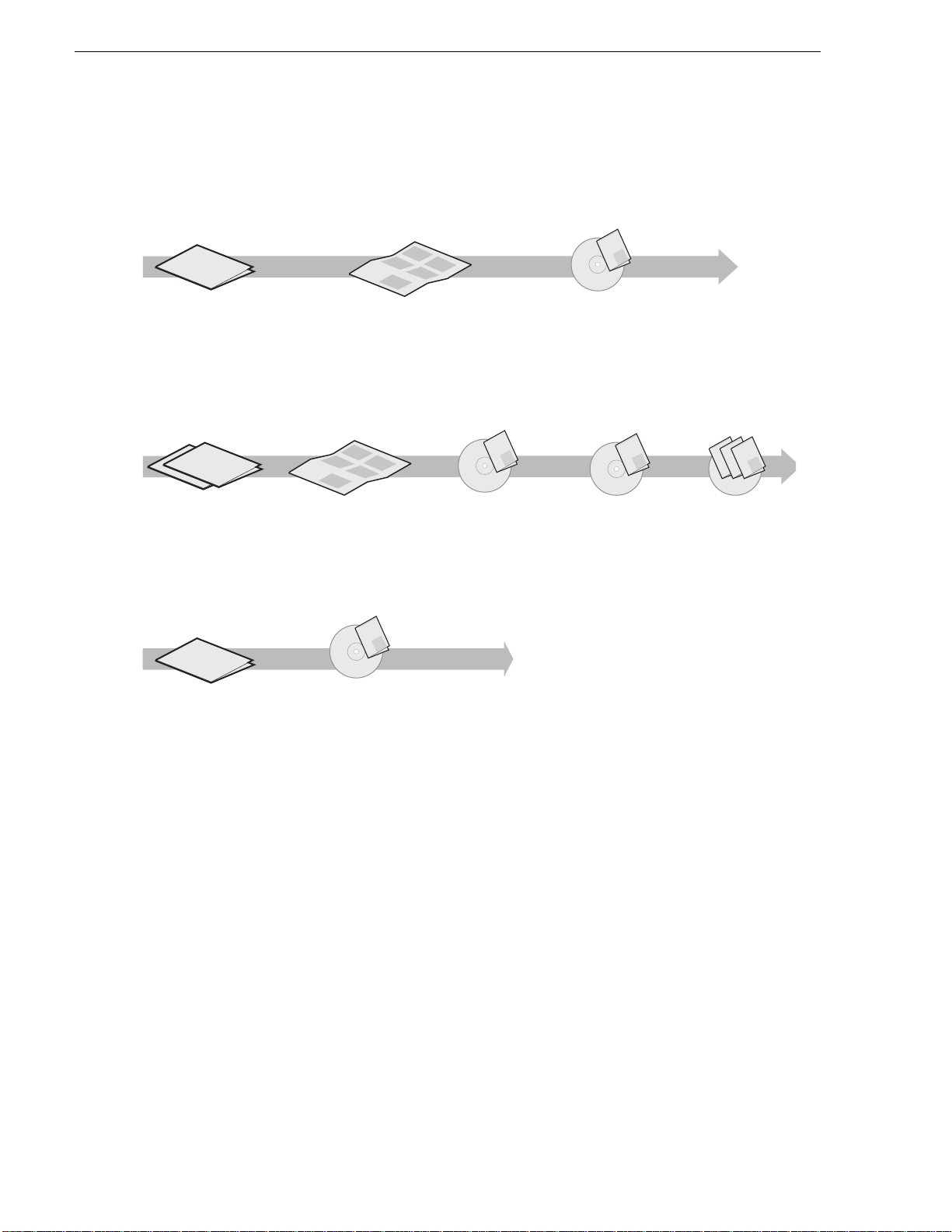
Getting more information
The following illustration shows the recommended order in which to reference the
documentation.
Quick Start Guide
Release Notes
12 K2 Media Client System Guide June 9, 2009
You receive this guide in the product packaging with your K2 Media Client. The
Quick Start Guide provides step-by-step installation instructions for basic installation
and operation of your K2 Media Client, including recording and playing clips.
The release notes contain the latest information about the K2 software shipped on
your system. The information in this document includes software upgrade
instructions, software specifications and requirements, feature changes from the
previous releases, and any known problems. Because rele ase no te s con ta in t he la test
information, they are printed out rather than included in the Documentation
CD-ROM.
Page 13

K2 Documentation CD
Except for the release notes, the full set of support documentation, including this
manual, is availabl e on the Documentati on CD-ROM that you rece ived with your K2
Media Client.
The K2 Documentation CD includes the following documents:
•
K2 Media Client Quick Start Guides — The Quick Start Gui des provides step-by-ste p
installation inst ructions for basic installation and oper ation of the K2 Media Clien t,
including recording and playing clips.
•
K2 Media Client User Manual — Describes the K2 Media Client and provides
instructions for operating the product in a variety of applications.
•
K2 Media Client System Guide — This guide p rovide s all t he inf ormati on you nee d
to go beyond factory defau lt settings and customize your system’s confi guration to
meet your site-specific needs.
•
K2 Media Client Service Manual — Conta ins informati on for solving common s etup
problems, as well as information on servicing and maintenance.
•
K2 Storage System Instruction Manual — Contains installation and configuration
procedures for shared storage options. Also includes administrative and
maintenance procedures.
Grass Valley Product Support
•
K2 Storage System Cabling Guide — Contains diagrams for cabling th e devi ce s of
the K2 Storage System.
•
RAID Storage Instruction Manuals — Contains procedures for troubleshooting and
servicing the different level RAID storage devices.
NetCentral documentation
The NetCentral product has its own documentation set, described as follows:
•
NetCentral User Guide — This is a printed manual. It provides instructions for
installing, using, and administering the NetCentral monitoring system.
•
NetCentral Help — From the N etCentral interface access on-line help as follows:
• For general help with NetCe ntral manag er, sel ect
This content is identica l to that in the NetCentral User Guide.
• For help specific to monitoring K2 Media Client system devices, select
Device Providers
and then select the monitored device.
Thomson Grass Valley Web Site
This public Web site contains all the latest manuals and documentation, and
additional support information. Use the following URL.
http://www.thomsongrassvalley.com.
Help | NetCentral Help Topics.
Help |
Grass Valley Product Support
For technical assistance, to check on the status of a question, or to report new issue,
contact Grass Valley Product Support via e-mail, the Web, or by phone or fax.
June 9, 2009 K2 Media Client System Guide 13
Page 14

Finding Information
Web Technical Support
To access support infor mation on the Web, v isit the pr oduct support Web page on the
Grass Valley Web site. You can download software or find solutions to problems.
World Wide Web: http://www.grassvalley.com/support/
Technical Support E-mail Address: gvgtechsupport@grassvalley.com.
Telephone Support
Use the following information to contact Product Support by phone.
International Support Centers
Our international support centers are available 24 hours a day, 7 days a week.
Support Center Toll free In country
France +800 80 80 20 20 +33 1 48 25 20 20
United States +1 800 547 8949 +1 530 478 4148
Authorized Local Support Representative
A local support represen ta ti ve ma y be avai l abl e in your count ry. To locate a support
center duri ng normal lo cal business hours, refer to the following list. This list is
regularly updated on the website for Thomson Grass Valley Product Support
(http://www.grassvalley.com/support/contact/phone/).
After–hours local phone support is also available for warranty and contract
customers.
Region Country Telephone
Asia
Pacific
Central America,
South America
North America
China +86 10 5883 7575
Hong Kong, Taiwan, Korea, Macau +852 2531 3058
Japan +81 3 6848 5561
Southeast Asia - Malaysia +603 7492 3303
Southeast Asia - Sing apore +65 6379 1769
Indian Subcontinent +91 11 515 282 502
+91 11 515 282 504
Australia, New Zealand +61 1300 721 495
All +55 11 5509 3440
North America, Mex ico, Caribbean +1 800 547 8949
+1 530 478 4148
14 K2 Media Client System Guide June 9, 2009
Page 15

Region Country Telephone
Europe
UK, Ireland, Isra e l +44 118 923 0499
Benelux – Netherland s +31 (0) 35 62 38 421
Benelux – Belgium +32 (0) 2 334 90 3 0
France +800 80 80 20 20
+33 1 48 25 20 20
Germany, Austria, Eastern Europe +49 6150 104 444
Belarus, Russia, Tadzhikistan, Ukraine, Uzbekistan +7 095 258 09 20
+33 (0) 2 334 90 30
Nordics (Norway, Sweden, Finland, Denmark, Iceland) +45 40 47 22 37
Southern Europe – Italy +39 02 24 13 16 01
+39 06 87 20 35 42
Southern Europe – Spain +34 91 512 03 50
Middle East,
Near East, Africa
Middle East +971 4 299 64 40
Near East and Africa +800 80 80 20 20
+33 1 48 25 20 20
June 9, 2009 K2 Media Client System Guide 15
Page 16

Finding Information
16 K2 Media Client System Guide June 9, 2009
Page 17
Chapter 1
!
!
!
Product Description
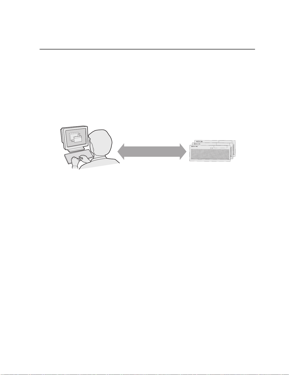
The K2 Media Client is a cost-effective Broadcast Enterprise Server that incorporates
IT server platform and storage technologies to deliver a networked solution to
facilities for ingest, playout, news integration, and media asset management. It is a
comprehensive platform that provides a suite of user applications and system tools.
Control
Point PC
Communication over
Ethernet network
Operation, configuration, and
monitoring from a remote location
K2 Media Clients
The K2 Media Client is desi gned for “headle ss” operation from a re mote control point
using Grass Valley Contr ol Point s oftware. You c an also us e the Microsoft Windows
Remote Desktop Connection appl icati on on your PC t o connect to the K2 syste m for
configuration or administration.
The K2 Media Client product is further described in the following sections:
• “K2 Media Client features” on page 18
• “Introducing K2 Media Client models” on page 21
• “Product identification” on page 25
• “Front panel indicators” on page 27
• “Rear panel view” on page 28
• “Considerations for first startup out of box” on page 30
• “K2 Media Client system overview” on page 31
June 9, 2009 K2 Media Client System Guide 17
Page 18

Chapter 1 Product Description
K2 Media Client features
This section provides an ove rview of K2 Media Client features . Refer to Appendix B,
Specifications for details.
The following features are common to all models:
• Four cha nnels (maximum) per c hassis
• SDI video inputs and outputs
• AES/EBU or embedded audio inputs and outputs.
• Redundant power supply, RAID 1 protected Windows XP system disk, cooling
fans for reliability
• RAID media storage
• Remote operation and configuration via AppCenter
• NetCentral™ provides remot e error reporting and monito ring via SNMP (Optional
for models using local storage only)
• Gigabit Ethernet
• AMP, VDCP, and BVW remote control protocols supported
• Remote control over RS-422 or Ethernet
• GPI Trigger (12 I/O)
Features of SDA-00 models
SDA-00 models record and play analog (composite) video and audio, as well as
digital (SDI) video and audio. These models are standard definition only.
SDA-00 models use dedicated encoders for recording and dedicated decoders for
playing. They have two record channels and t wo play channels. You ca n encode and
decode video using the DV25 or MPEG-2 c ompression sta ndards. You can play clips
of any of these compression types through a play channel without any configuration
changes. For example, you can play DV25 and MPEG-2 clips back-to-back on the
same timeline.
The complete product nomenclature for this model is K2-SDA-22, which designates
the channel configuration as two record and two play. Internal storage and external
storage models are av ailable. Also refer to “Introducing the SDA-00 K2 Media
Client” on page 21.
18 K2 Media Client System Guide June 9, 2009
Page 19

Features of SD-00 models
SD-00 models have bi-directional video codecs, which means each of the four
channels support both record and play operations. These models are standard
definition only.
You can encode and decode video using the DVCAM, DVCPRO or MPEG-2
compression standards. You can play clips of any of these compression types thr ough
any play channel without any conf igurati on changes. For example, you can play DV,
DVCPro25, DVCPro50, and MPEG-2 clips back-to-back on the same timeline.
The complete product nomencl ature for this model is K2-SD-04 , which designates the
channel configuration as four record/play channels. Internal storage and external
storage models are available. Also refer to “Introducing the SD-00 K2 Media Client”
on page 21.
Features of HD-00 models
HD-00 models can process either high definition (HD) or standard definition (SD)
video. However, only the MPEG-2 compression standard is used in these HD/SD
models. In addition, these mod els use ded icated enco ders for rec ording an d dedicated
decoders for playing . The number and type (r ecord or play) of channels in the cha ssis
is determined by the model.
Features of SD-00 models
Record channels can record either SD or HD through an HD encoder. Play channels
play both SD and HD clips throu gh an Agile HD decode r. Both HD an d SD clips are
played out in the fo rmat specif ied for t he outp ut assigne d to the cha nnel. All clips ar e
either up- or down-converted appropriately to play on that output, and their aspect
ratios are adjust ed. For example, you can play 50 Hz SD 625, HD 1080i at 25 Hz, and
HD 720p at 50 Hz clips back-to-back on the same timeline.
HD-00 models support encode and decode of SD VBI data and HD Ancillary data,
with appropriate up/down conversion for playout.
The complete produc t nomenclature for this model designa te s c h an nel configuration
as follows:
• K2-HD-02 — No record channels, two play channels
• K2-HD-03 — No record channels, three play channels
• K2-HD-04 — No record channels, four play channels
• K2-HD-12 — One record channel, two play channels
• K2-HD-13 — One record channel, two play channels
• K2-HD-22 — Two record channels, two play channels
Internal stor age a nd ext ern al s torag e model s are a vaila ble. Also ref er t o “Introducing
the HD-00 K2 Media Client” on page 22.
Features of internal storage models
SDA-00, SD-00, and HD-00 models are available with internal media storage, with
options for five media drives or ten media drives. In addition, there are two drives
configured as a RAID 1 mirrored pair, which together are the system drive. This
June 9, 2009 K2 Media Client System Guide 19
Page 20

Chapter 1 Product Description
makes the internal storage K2 Media Client a self-contained, stand-alone unit, with
no external devices fo r storage, audio, or video c onnections required. You can t ransfer
media in and out of the internal storage K2 Media Client via Gigabit Ethernet.
Refer to Chapter 4, Managing Internal Storage for more information.
Features of external storage models
SDA-00, SD-00, and HD-00 models are available as external storage clients. The
external storage K2 Media Client contains two internal disk drives that make up the
RAID 1 system drive. There are no media drives in an external storage K2 Media
Client. There are two types of external storage for media, as follows:
• Shared storage — Multiple external storage K2 Media Clients connect to the K2
Storage System via Gigabit Ethernet to share a common pool of storage. Refer to
Chapter 8, Shared Stor age and the K2 Storage System Instruction Manual for m ore
information.
• Direct-connect storage — A single K2 Media Client with the optional Fibre
Channel board install ed connects direct ly to its own exte rnal RAID storage devic e.
This makes the direct -conne ct K2 Medi a Cli ent a self- conta ined, s tand-a lone u nit,
with no external device s for storage, audio, or video connections requi red. You can
transfer media in and out of the direct-connect K2 Media Client via Gigabit
Ethernet. Refer to Chapter 7, Direct Connect Storage for more information.
20 K2 Media Client System Guide June 9, 2009
Page 21
Introducing K2 Media Client models
Introducing K2 Media Client models
This section provides overview descriptions of the different channel configurations.
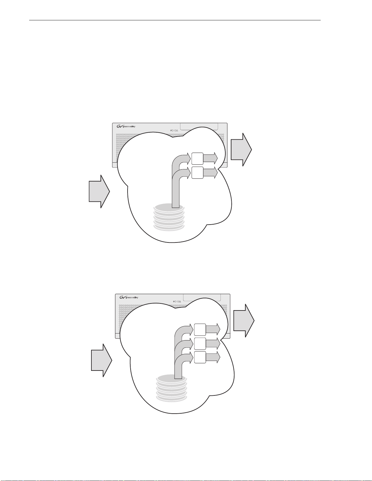
Introducing the SDA-00 K2 Media Client
The SDA-00 model has two input channels and two output channels. Input channels
are configurable to reco rd either Analog or SDI. Output channe ls can play both analog
and SDI at th e same time. The illustrat ion below shows this model with internal
storage. An external storage model is also available.
!
Analog
or SDI
Analog
or SDI
Record
Channels
R2
Channels
P1R1
P2
Internal Storage
SD
Media
in
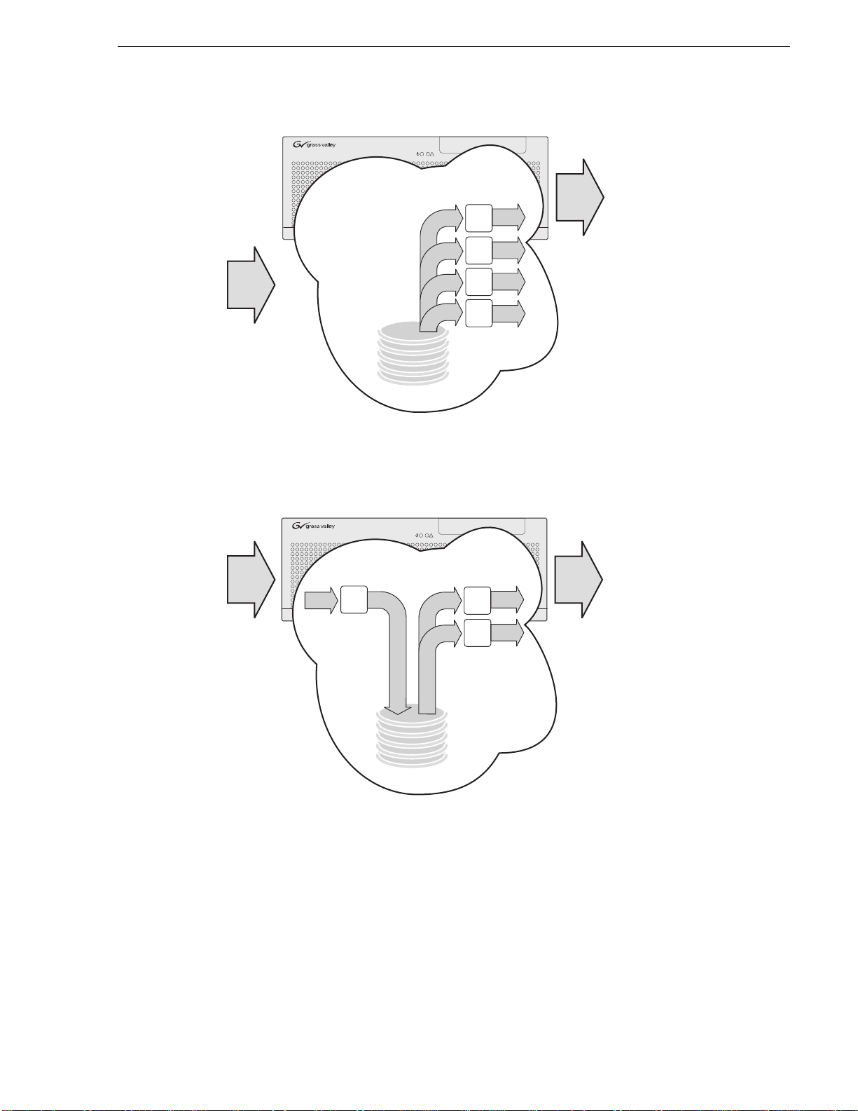
Introducing the SD-00 K2 Media Client
The SD-00 model has four bidirectional channels. Each bi-directional channel
supports both record and play operations. You can have four record channels, four
play channels, or a combination of record and play channels. The illustration below
shows this model with internal storage. An external st orage model is also available.
!
Play
Analog
SDI
Analog
SDI
SD
Media
out
CH
Record
1
Bi-directional
Channels
CH
2
Internal Storage
Play Play
CH3CH
SD
Media
out
4
SD
Media
in
Record
June 9, 2009 K2 Media Client System Guide 21
Page 22
Chapter 1 Product Description
Media
transfer
in
Media
out
Agile Play
Channels
HD or SD SD or HD
HD or SD SD or HD
Internal Storage
P1
P2
Media
out
Agile Play
Channels
HD or SD SD or HD
HD or SD SD or HD
HD or SD SD or HD
Internal Storage
P1
P2
P3
Media
transfer
in
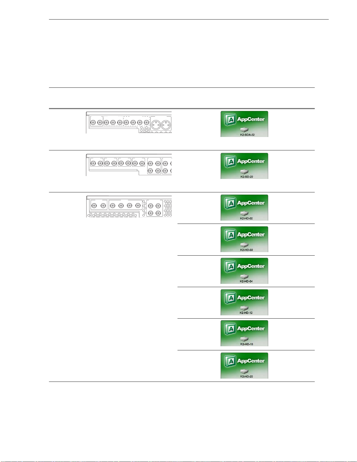
Introducing the HD-00 K2 Media Client
There are six different channel configurations for HD-00 models, as shown in the
following illustrations. Input channels can be configured to record either SD or HD.
Output channels are Agile, in that you can configure each channe l to output either SD
or HD; the clips (eithe r SD or HD) are automatical ly up-converted or do wn-converted
accordingly. The illustrations below show internal storage models. External storage
models are also available.
K2- HD-02 channels
!
K2-HD-03 channels
!
22 K2 Media Client System Guide June 9, 2009
Page 23
K2-HD-04 channels
Media
out
Agile Play
Channels
HD or SD SD or HD
HD or SD SD or HD
HD or SD SD or HD
HD or SD SD or HD
Internal Storage
P1
P2
P3
P4
Media
transfer
in
Media
in
Media
out
Agile Play
Channels
HD or SD Record
Channel
HD or SD SD or HD
HD or SD SD or HD
Internal Storage
P1R1
P2
HD or SD
Introducing the HD-00 K2 Media Client
!
K2-HD-12 channels
!
June 9, 2009 K2 Media Client System Guide 23
Page 24

Chapter 1 Product Description
Media
in
Media
out
Agile Play
Channels
HD or SD Record
Channel
HD or SD SD or HD
HD or SD SD or HD
HD or SD SD or HD
Internal Storage
P1R1
P2
P3
HD or SD
Media
in
Media
out
Agile Play
Channels
HD/SD Record
Channels
HD or SD SD or HD
HD or SD SD or HD
Internal Storage
P1R1
R1
P2
HD or SD
HD or SD
K2-HD-13 channels
!
K2-HD-22 channels
!
24 K2 Media Client System Guide June 9, 2009
Page 25
Product identification
R1 IN R1 IN
CH 1/2
CH 1/2
CH 3/4CH 3/4
P1 OUT
P1 OUT 1
LR
P1 OUT 2
CMPST R1 & P1
SDI R1 & P1
AES/EBU R1 & P1
R1 IN
P1 OUT
AUD MON OUT
SDI CH 1
IN OUT
SDI CH 2
IN OUT
SDI CH 3
IN OUT
SDI CH 4
IN OUT
AES/EBU CH 1
IN OUT
1-2
3-4
1-2
3-4
1-2
3-4
AES/EBU CH
IN OU
SDI IN
R1 (Opt) R2 (Opt)
SDI OUT
P1 P2 P3 (Opt) P4 (Opt)
AES/EBU IN
R1 (Opt)
1-2 1-2
3-43-4
R2 (Opt)
The following table summariz es the ways you can i denti fy the spe cific clie nt-ty pe o f
a K2 Media Client.
Product identification
For this type
of K2 Media
Client… The rear panel has these connectors…
SDA-00
Refer to “SDA-00 model rear panel view”
on page 28.
SD-00
Refer to “SD-00 model re ar pa ne l vie w ”
on page 29.
HD-00
Refer to “HD-00 model rear panel view ”
on page 30.
The chassis
a
label
displays…
In AppCenterb,
Help | About
displays…
And unique
features are as
follows:
K2-SDA-22 SD Analog/SDI
K2-SD-04 SD Bi-directional
channels
K2-HD-02 HD/SD two play
channels
K2-HD-03 HD/S D three play
channels
K2-HD-04 HD/SD four play
channels
K2-HD-12 HD/SD one
record, two play
channels
K2-HD-13 HD/SD one
record, three play
channels
K2-HD-22 HD/SD two
record, two play
channels
a.
Refer to the diagram below to locate the label.
b.
Make sure the channel currently selected in AppCenter is on the K2 Media Client you are identifying.
June 9, 2009 K2 Media Client System Guide 25
Page 26
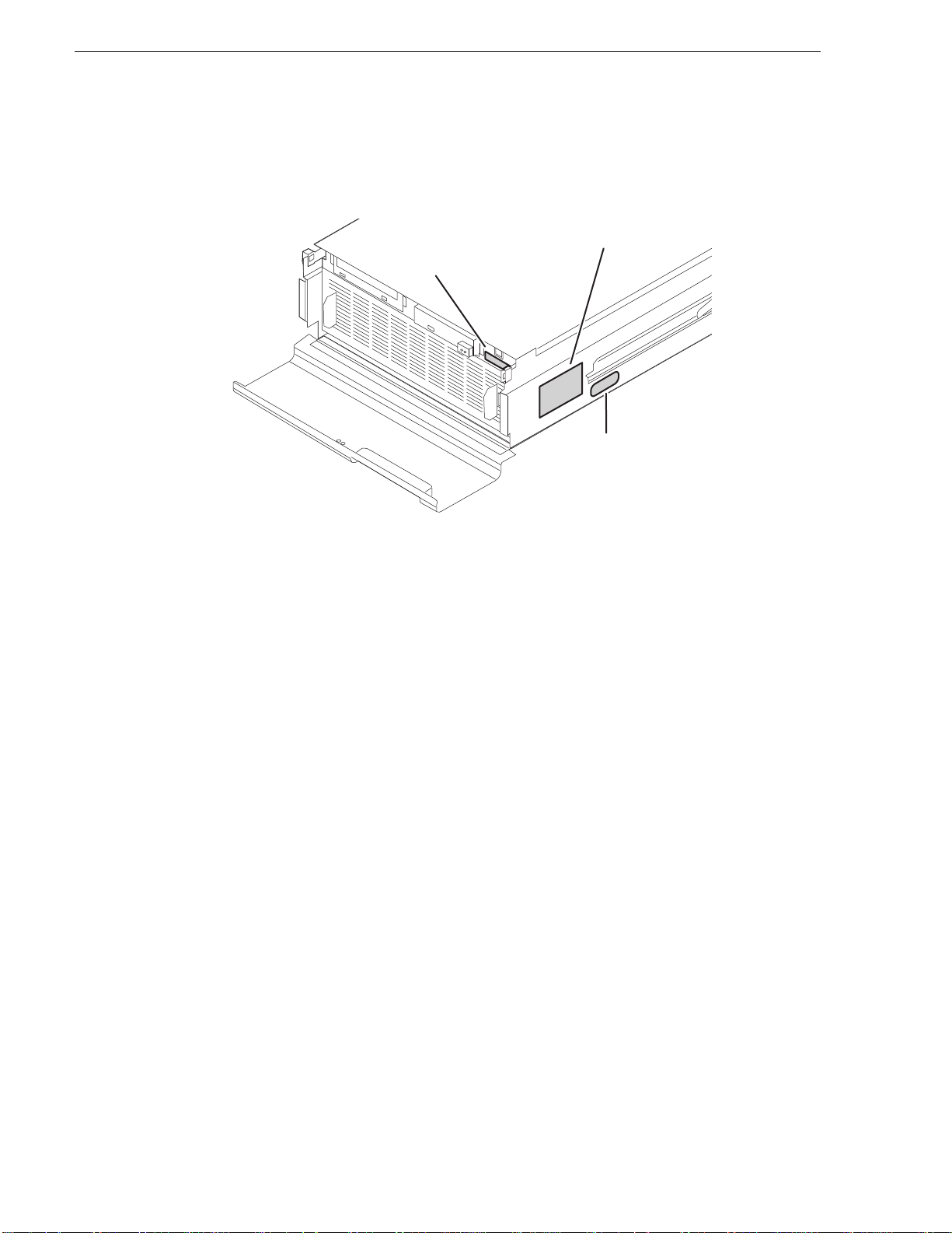
Chapter 1 Product Description
Serial Number
K2 Product Model
The K2 Media Client has labels affixed to the chassis that provide product
identification as in the following diagram:
(e.g. K2—01AA00010)
This is also the factory
default hostname
(e.g. K2–HD–22)
Windows Key
Refer to the product model label when setting up RS-422 connections, as explained
in “RS-422 connections” on page 178.
26 K2 Media Client System Guide June 9, 2009
Page 27
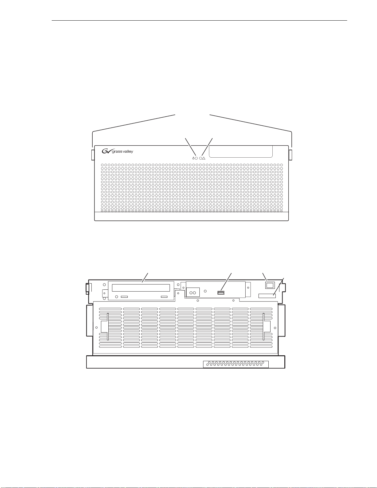
Front panel indicators
Bezel Release
Standby
CD
USB
l
er
With the front bezel in place, the indicator LEDs are visible. The LEDs indicate the
status of the machine. For example, when the Service LED is a steady yellow light,
this could signify t hat one of the power cables is unpl ugged. For more i nformation on
indicator LEDs, see the K2 Media Client Service Manual.
Front panel indicators
Buttons
Power
LED
Service
LED
!
With the front bezel f li ppe d down, you have access to th e s tandby switch, USB port,
and the removable media drive.
Drive
Port
Switch
K2-01AA00015
Seria
Numb
June 9, 2009 K2 Media Client System Guide 27
Page 28
Chapter 1 Product Description
Reference
A
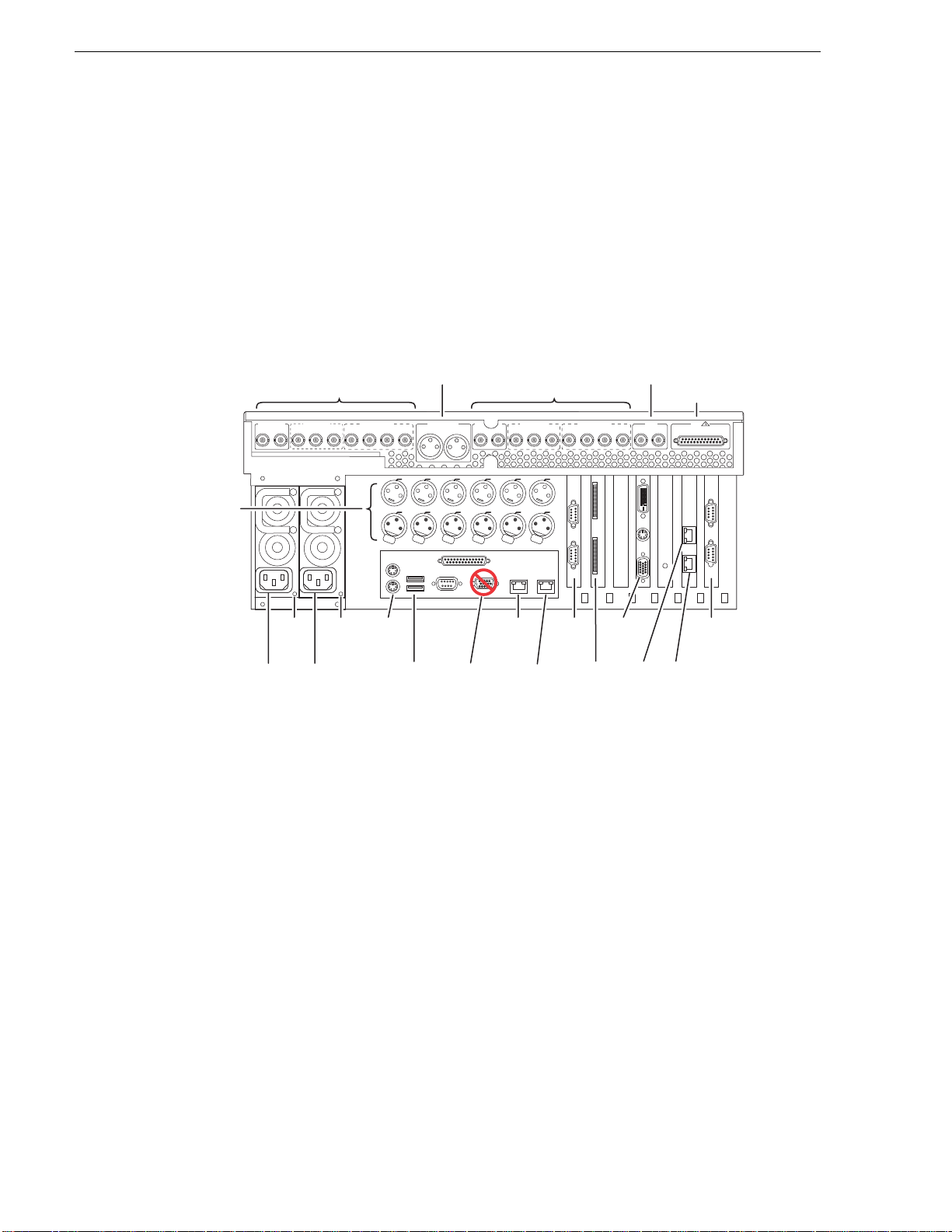
Rear panel vi ew
The following drawings identify the rear panel connectors and components. Some
cards are in different locations for the different models.
NOTE: All models can have an optional Fibre Channel board. Models with the
Fibre Channel option do not have the GigE port 3/port 4 board.
SDA-00 model rear panel view
LTC and
nalog Audio
In/Out
Audio Monitor
Channels R1 & P1 In/Out
P1 OUT
Power
Good
LED
SDI R1 & P1
P1 OUT 1
Power
Cord
P1 OUT 2
Power
Good
LED
AES/EBU R1 & P1
R1 IN
CH 1/2
Keyboard
/Mouse
CH 1/2
P1 OUT
Push
CH 3/4CH 3/4
P1 LTC
Push
USB
CMPST R1 & P1
R1 IN R1 IN
Power
Cord
*
systems have one RS-422 board.
Out
Channels R2 & P2 In/Out
AUD MON OUT
LR
CMPST R2 & P2
R2 IN R2 IN
P2 OUT
P1 CH1
P1 CH2 P2 LTC P2 CH1 P2 CH2
Analog
Audio
Push
Push
Do Not
Use
Push
GigE
Port 1
SDI R2 & P2
P2 OUT 1 P2 OUT 2
Analog
Audio
AES/EBU R2 & P2
R2 IN
CH 1/2
CH 1/2
OUT
R2 CH2R2 CH1R2 LTCR1 CH1 R1 CH2R1 LTC
IN
Push
RS-422* RS-422*
GigE
Port 2
Do Not
Use**
Not present on some external
**RS-422 configuration varies. Some
storage models.
(Loop-Thru)
P2 OUT
COMPOSITE LOOP
CH 3/4CH 3/4
VGA
Display
GigE
Port 3
In
GPI
REF
GPI
GigE
Port 4
!
THRU
Refer to “RS-422 connections” on page 178 to connect and configure for RS-422
control.
28 K2 Media Client System Guide June 9, 2009
Page 29
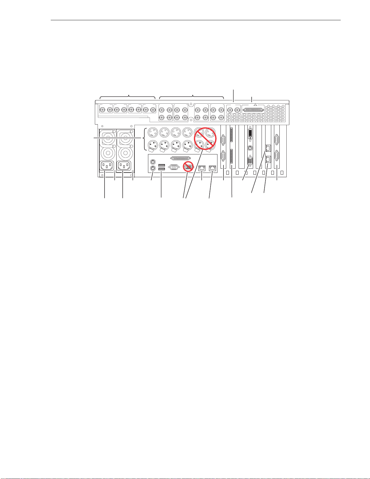
SD-00 model rear panel view
!
Reference
C
Video In/Out
SDI CH 1
SDI CH 2
SDI CH 3
SDI CH 4
IN OUT
IN OUT
IN OUT
IN OUT
AES/EBU CH 1
IN OUT
1-2
3-4
1-2
3-4
Audio In/Out
AES/EBU CH 2
IN OUT
1-2
1-2
3-4
3-4
AES/EBU CH 3
IN OUT
1-2
3-4
1-2
3-4
(Loop-Thru)
AES/EBU CH 4
IN OUT
1-2
3-4
1-2
3-4
In
REF
COMPOSITE LOOP
THRU
SD-00 model rear panel view
GPI
GPIO
LTC
In/Out,
Per
hannel
Power
Power
Good
Good
LED
LED
Power
Power
Cord
Cord
*
systems have one RS-422 board.
OUT OUT OUT OUT
LTC CH 1 LTC CH 2 LTC CH 3 LTC CH 4 UNUSED UNUSED
IN
IN IN IN
Push
Push
Push
Push
Keyboard
/Mouse
USB
Do Not
Use
Push
Push
Do Not
Use**
VGA
Display
GigE
Port 1
RS-422* RS-422*
GigE
Port 2
Not present on some external
**RS-422 configuration varies. Some
storage models.
GigE
Port 3
GigE
Port 4
Refer to “RS-422 connections” on page 178 to connect and configure for RS-422
control.
June 9, 2009 K2 Media Client System Guide 29
Page 30
Chapter 1 Product Description
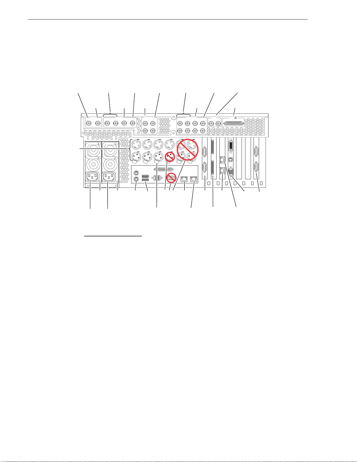
HD-00 model rear panel view
R1*
Video In
(Optional)
LTC
In/Out,
Per
Channel
P1 & P2
Video Out
(All Models)
R2*
Video In
(Optional)
SDI IN
R1 (Opt) R2 (Opt)
Power
Cord
*Key to Optional
Channels
Power
Good
LED
Power
Cord
P1 P2 P3 (Opt) P4 (Opt)
Channel Models
R1
R2
P1
P2
P3
P4
HD-12, HD-13
HD-22
All
All
HD-03, HD-04, HD-13
HD-04
P3*
Video Out
(Optional)
SDI OUT
Power
Good
LED
P4*
Video Out
(Optional)
Audio In
(Optional)
Push
PS2
Keyboard
/Mouse
R2*
Audio In
(Optional)
R1*
AES/EBU IN
R1 (Opt)
R2 (Opt)
1-2 1-2
3-43-4
P1
P2 P3(Opt) P4(Opt) UNUSED UNUSED
HOUSE
P2(Opt)R1(Opt)
LTC
Push
Push
Push
Do Not
USB
House LTC
(Input for Time
of Day source)
Use
P1 & P2
Audio Out
(All Models)
P3*
Audio Out
(Optional)
AES/EBU OUT
P1
P2 P3 (Opt) P4 (Opt)
1-2 1-2 1-2 1-2
3-4 3-4 3-4 3-4
UNUSEDUNUSEDUNUSED
Push
Push
GigE
Port 1
GigE
Port 2
Not present on some external
**
P4*
Audio Out
(Optional)
REF
COMPOSITE LOOP
THRU
LTC OUT
LTC I N
Do Not
Use**
GigE
Port 4
RS-422 RS-422
storage models.
Reference In
(Loop-Thru)
GPI
GPIO
!
VGA
Display
GigE
Port 3
Refer to “RS-422 connections” on page 178 to connect and configure for RS-422
control.
Considerations for first startup out of box
When you receive a K2 system from the factory, one or more End User License
Agreements (EULAs) appear on the screen at first startup. Software licensing
agreements require that yo u accept these E ULAs. Whe n you do s o, star t up pro cesses
can proceed. This behavior occurs only at first startup. Subsequent startups do not
exhibit this behavior.
The following are examples of the EULAs that you might see.
On a K2 Media Client, at first startup the following behavior occurs:
• A Microsoft SQL End User License Agreement (EULA) opens on the screen.
On a K2 Media Server, at first startup the following behavior occurs:
• A Microsoft SQL and Windows Server 2003 End User License Agreement
(EULA) opens on the screen.
30 K2 Media Client System Guide June 9, 2009
Page 31

K2 Media Client system overview
ts
ts
*
The K2 Media Client is a standar d PCI bus-bas ed Windows compute r with exte nsive
enhancements to provide the video d is k recorder functionality. This section explains
the major ar chitectur al blocks.
Inputs and Outputs:
Audio, Video , Timecode, Reference, GPI
Real
Time
System
Application
System
RAID**
Controller
SCSI**
Interface
SCSI**
Backplane
Encoder
Board
(HD option)
PCI
Bus
Decoder
Board
(HD option)
Codec Board
Real Time
Processor
Board
PCI Bus
ATX Motherboard
PCI
Bus
USB
PCI
Bus
XLR
Board
Graphics
Board
RS422*
Boards
Dual
Ethernet
Board
K2 Media Client system overview
VGA Monitor
Remote
Control
Devices
Ethernet Por
Ethernet Por
Mouse
System and
***Media Drives
System
Resources
*Some K2 Media Clients have a PCI RS-422 board
**Some models have SATA drive connector boards rather than a SCSI interface
and backplane
**Media Drives not in external storage models
CD-RW
Power Supply
Keyboard
Fan Module
June 9, 2009 K2 Media Client System Guide 31
Page 32

Chapter 1 Product Description
Application System
The Application s ystem archit ecture is similar to that of standard PC- type computers .
It uses an ATX form factor motherboard that prov ides PCI boar d slots for e xpansion,
built in Ethernet, and USB ports.
Standard boards are as follows:
• Graphics Board — This boa rd provides en hanced per formance for s creen graphic s
and a connection for a VGA monitor.
• RS422 Boards — K2 Media Clients have been manufactured with two types of
RS-422 configurations, as follows:
• A K2 Media Client can have two RS-422 adapters. Each adapter is connected
via an internal USB cable to the motherboard, so while a RS-422 adapter does
occupy a rear panel slot, it does not plug into a PCI bus. Each adapter pr ovi des
two RS-422 ports for connecti ng equipment for remote control of the K2 Media
Client.
• A K2 Media Client can have one RS-422 ada pte r. The adapter is con nect ed via
PCI slot to the motherboard. The adapter includes an external interface with
eight ports. On the external interfac e, ports 1–4 are a ctive. This provides the four
ports for connecting equipment for remote control of the K2 Media Client.
• Dual Ethernet Board — This board provides additional Gigabit Ethernet ports,
which are used for redundant connections.
• RAID Controller — This board provides the RAID functionality and SCSI
connection for the int ernal disk drives. Thi s includes both media an d system drives
for internal storage models, but just the RAID 1 pair of system drives for external
storage models. The external ports on this board are not used. Some external
storage models provide RAID controller functional ity on the motherboa rd instead.
Also on these models, RAID drive connections are provided by a SATA drive
connector board rather than a SCSI backplane.
The Application system uses a Windows opera ting sys tem up on which al l K2 Media
Client applications run for configuration and control of the unit.
Real Time System
The Real Time system uses Grass Valley boards to provide the core video disk
recorder functionality. Primary components are as follows:
• Real Time Processor (RTP) Board — This board provides a dedicated processor
and connections for media access and processing. It functions as a riser board,
connecting to the PCI slot below and the Codec board above.
• Codec Board — This board hosts the circuits responsible for encoding/decoding
video and processing audio and timecode. It also provides the majority of the
media-related input and output connectors.
• XLR Board — This board provides XLR connectors. It is primarily an extension
of the codec board to allow the space and orientation required for XLR
connections.
32 K2 Media Client System Guide June 9, 2009
Page 33

The Real Time system uses a dedicated operating system. This operating system runs
Application System
Applications
Media File System
Storage System
Real Time System
Media control
relegated to
Application processor
Media processing
relegated to Real Time
processor
Inputs and Outputs
on the RTP board and manages all the hardware involved in controlling the flow of
video, audio, timecode, genlock, and GPI in and out of the K2 Media Client.
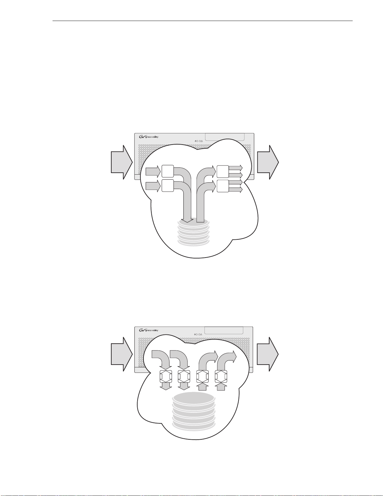
Media control and processing
The following section e xplains how the Applica tion system and the Real Time s ystem
work together to provide K2 Media Client functionality.
Media control and processing
The high processin g r equirements of digi ta l vi deo can overwhelm the pr ocessor on a
standard d esktop PC, resulting in wait-times that destroy the vid eo’s essent ial
real-time aspect. The K2 Media Client avoids this problem by providing dedicated
systems that isolat e proc essin g ne eds. The compo nents t hat wor k toge ther to pro vid e
this functionality are as follows:
Application system is, at its core, a conventional desktop PC-type system. In the
The
K2 Media Client it is dedicated to control, configuration, and networking functions
that do not require real-time accuracy. The Application system has the following
components:
• Application software pr ovides the user interface fo r operating the K2 Media Client.
June 9, 2009 K2 Media Client System Guide 33
Page 34

Chapter 1 Product Description
The software runs as Windows programs.
• The Media File system manages clips. It includes a database that associates the clip
with its video, audio , and timeco de files and a de dicated fi le system (separ ate from
the Windows file system) that controls access to the raw data that makes up each
file. Any reading and writing of clips, be it through play and record operations or
through file transfers and media streaming, is managed by the database. The
database and file system run as Windows programs.
The
Storage system incl udes the media disk drives , control lers , driver s, and ada pters
necessary for access and movement of the data. While the primary data flow is within
the overall control of the Real Time system, some components and their
communication pathways cross over into the Application system. For example, the
RAID controller board plugs into the motherboard and accesses media drives in
internal storage model s, yet it is cont rolle d by Windows. The medi a driv es appea r as
the V: drive to the Windows operating system.
Real Time system manages the media flow between the Storage system and the
The
inputs and outputs. The Real Time system has a dedicated processor and
time-sensitive mechanisms to serve media processing needs while maintaining
real-time accuracy.
When you control play an d record operati ons from within the Application sys tem you
trigger a chain of events that eve ntually cro sses over into the Real Time system and
results in media ac cess. The f ollowing sequ ence is an ex ample of this type of chai n of
events:
1. A user operates the Player application to play a particular clip. The Player
application asks the Media File system for permissi on to access the clip. The Media
File system grants access. In shared storage models, the Media File system
enforces shared storage policies in order to grant the access. When access is
granted, the Player app l ication initiates play access to the clip.
2. The database identifies the files that make up the clip and the file system instructs
the Storage system to open access to the files.
3. The Storage system finds the raw data and opens the appropriate read access. At
this point both the Application system and the Real Time system are involved.
Windows controls the media drives and controllers, so the Real Time system
makes file requests to Windows and it causes the data to be transferred to buffers
on the Real Time process or. The data i s then avai labl e to the Real Time syst em so
that it can be processed at exactly the right time.
4. The Re al Time system proce sses the media, decompr esses it, adjust s its timing, and
moves it as required to play the clip as specified by the user.
Loop through and E to E
Each of the K2 Medi a Clie nt mode ls has d ifferen t mecha nis ms and behavio rs re late d
to input signals routed to output connectors, as described in the following sections.
Also refer to Appendix A, Remote control protocols for infor mation regardin g E to E
commands.
34 K2 Media Client System Guide June 9, 2009
Page 35

SDA-00 E to E
R1
Record
Channel 1
R2
Record
Channel 2
P2
Playd
Channel 2
P1
Play
Channel 1
P1
Output
Circuit
PB/EE Switch Path
PB/EE Switch Path
P2
Output
Circuit
R2
Input
Circuit
R1
Input
Circuit
SDA-00 models have an E to E path provided for monit orin g purposes , as illu strat ed
in the following diagram.
Loop through and E to E
When E to E mode is enabled, the play channel video and audio outpu ts are switc hed
to the correspondin g rec or d chan nel inputs when the play channe l is in s top mode or
when no clip is loaded. The following table descri bes play channel operation
depending on the E to E selection.
E to E Setting Play chann el mod e Play channel output
Disabled Play, FF, Rewind
Stop
Eject
Enabled Play, FF, Rewind
Stop
Eject
a.
Output is black if no video input is connected.
Show clip
Show clip
Show black
Show clip
Show input
Show input
a.
a.
If E to E mode is enabled, you can connect an external reference signal which is
synchronous to the video input. This eliminates artifacts on the play channel output
(periodic vertical shift) due to routing an asy nchronous signal through th e SDA-00 K2
Media Client. However, this is not required for recording, as the SDA-00 K2 Media
Client can record asynchronous signals.
NOTE: E to E is provided for moni toring the record channel, and is not intend ed
as a program switch.
June 9, 2009 K2 Media Client System Guide 35
Page 36

Chapter 1 Product Description
SD-00 loop through
The Player/Recorder application has a “E-to-E (LoopThru) mode” selection on the
Control menu. This mode applies when t he channel is under local AppCent er control
as well as when it is unde r remote control, for all protocols.
This “E-to-E (LoopThru) mode ” feature al lows you to monitor th e video that i s being
recorded. The vid eo is routed back essentially untouc hed. Any AES audio or LTC that
is on the input video is still there on the loop through. The SD-00 K2 Media Client
and the loop through vi deos mu st be lo cke d to a vide o refe rence f or t he loop t hrough
feature to work properly. This “E-to-E (LoopThru) mode” feature should not be
confused with true E to E, su ch as that on the SDA-00 K2 Media Clie nt . True E to E
is not supported on the SD-00 K2 Media Client.
When “E-to-E (LoopThru) mode” is not selected, the channel behaves as follows:
• “PB” is displayed on the channel pane, next to the Timecode Source indicator.
• When no clip is loaded, black plays out.
• When a record operation stops, Recorder becomes Player and the clip remains in
the Player. The clip’s last frame plays out.
When “E-to-E (LoopThru) mode” is selected, the channel behaves as follows:
• “EE” is displayed on the channel pane, next to the Timecode Source indicator.
• When no clip is loaded, the signal that is currently present at the channel input
plays out.
• When a record operat ion stops, Recorder stay s Recorder and the clip re mains in the
Recorder. The signal that is curr ently prese nt at the cha nnel input plays out.
HD-00 loopback
HD-00 models provide a lo opback fea ture with which you ca n monitor t he video t hat
is being recorde d. The video is route d back ess entiall y untouche d. Any ancil lary dat a
or embedded audio that is on the input video is sti ll there on the loopb ack. The HD-00
K2 Media Client and the loopback vid eos must be loc ked to a video refe rence for the
loopback feature to work properly.
Loopback should not be confused with an E to E feature. E to E is not supported on
the HD-00 K2 Media Client.
NOTE: The loopback path is for monitoring purposes only.
36 K2 Media Client System Guide June 9, 2009
Page 37

Loop through and E to E
The loopback mapping for HD-00 models is illustrated in the following diagrams.
Loopback
HD-00 models with
two record channels
R1 to P4
R2 to P3
Video
input
Video
loopback
Loopback
HD-00 models with
one record channel
R1 to P4
Video
inpu
t
Video
loopback
June 9, 2009 K2 Media Client System Guide 37
Page 38

Chapter 1 Product Description
Locations of rear panel boards
Boards are mapped to rear panel slots as follows. When viewed from the rear, slot 1
is on the right and slot 7 is on the left.
Type I motherboard
Slot SDA-00 and SD-00 HD-00 Comments
1———
2 Dual Ethernet or
Fibre Channel (optiona l)
3 USB RS-422 dual-port USB RS-422 dual-port Occupies a rear panel slot but
4 Graphics Graphics Plugs into a PCI bus.
5 RTP Dual Ethernet or
6 RAID controller RAID controller Plugs into a PCI bus.
7 USB RS-422 dual-port USB RS-422 dual-port Occupies a rear panel slot but
Type II motherboard
Slot SDA-00 and SD-00 HD-00 Comments
1 Fibre Channel (optional) Fibre Channel (optional) Plugs into a PCI bus.
2 Dual Ethernet RTP Plugs into a PCI bus.
3 PCI RS-422 8 port PCI RS-422 8 port Plugs into a PCI bus.
4 Graphics Graphics Plugs into a PCI bus.
5 RTP Dual Ethernet Plugs into a PCI bus.
6 RAID controller RAID controller Plugs into a PCI bus.
7 — — Plugs into a PCI bus.
RTP Plugs into a PCI bus.
does not plug into a PCI bus.
Plugs into a PCI bus.
Fibre Channel (optiona l)
does not plug into a PCI bus.
Type III motherboard
Slot SDA-00 and SD-00 HD-00 Comments
1 USB RS-422 dual-port USB RS-422 dual-port Occupies a rear panel slot but
does not plug into a PCI bus.
2 Dual Ethernet RTP Plugs into a PCI bus.
3 Fibre Channel (optional) Fibre Channel (optional) Plugs into a PCI bus.
4 Graphics Graphics Plugs into a PCI bus.
5 RTP Dual Ethernet Plugs into a PCI bus.
6 RAID controller RAID controller Plugs into a PCI bus
7 USB RS-422 dual-port USB RS-422 dual-port Occupies a rear panel slot but
does not plug into a PCI bus.
a.
This board not present on some external storage models.
38 K2 Media Client System Guide June 9, 2009
a
.
Page 39

RS-422 ports
GPIO
!
1-2
3-4
OUT
REF
COMPOSITE LOOP
THRU
!
Port 1
Port 2
Port 3
Port 4
(COM 5)
(COM 6)
(COM 3)
(COM 4)
Port 1
(Com 3)
Port 2
(Com 4)
Port 3
(Com 5)
Port 4
(Com 6)
K2 Media Clients have been manufact ured with two typ es of RS-422 conf igurations,
as follows:
• Two dual-port adapters, connected to the motherboard via USB cables
• One adapter (with external 8-port interface), connected to motherboard via PCI slot
Refer to the appropriate illustration below.
The Windows COM port assignments to the physical RS-422 connectors are
described in the following illustrations. For information on the relationship between
RS-422 ports and K2 Media Client channels, see Appendix A, Remote control
protocols. For RS-422 po rts that corresp ond to int ernal USB hu bs, refer to “Enabling
and disabling the USB ports” on page 148.
NOTE: The designations Port 1, Port 2, Por t 3, Port 4 in these illust rations r efer to
the labelling of the physical RS-422 connectors. Do not confuse this with other
types of ports.
RS-422 ports
REF
4
COMPOSITE LOOP
T
1-2
3-4
RS-422
Port 3
Port 4
SCSI
GPIO
THRU
1
2
3
4
RS-422
10Bt
Port 1
100Bt
Port 2
1000Bt
June 9, 2009 K2 Media Client System Guide 39
Page 40

Chapter 1 Product Description
Ports used by K2 services
The following ports are use d by th e appli cations and syste m tools o f the K2 family of
products:
Port # Type of
connection
3389 TCP Remote Desktop Used by SiteConfig .
18262 TCP GV ProductFrame
18263 UDP ProductFrame
18264 UDP ProductFrame
49168 HTTP Grass Valley
49169 TCP
49170 HTTP Grass Valley
49171 TCP Grass Valley
49172 HTTP Grass Valley
Service name Description
Used by SiteConfig.
Configuration Service,
ProductFrame
Discovery Agent
Service
GV NetConfig Device Broadcast /Unicast
Discovery Agent
Service
Discovery Agent
Service
K2 Config
Transfer Queue Service
AppService
Storage Utility Host
Protocol. Used by SiteConfig. Sent by
ControlPoint, received by Devices
GV NetConfig Controll er Protocol. Used by
SiteConfig. Sent by Devices, received by
ControlPoint
K2 System Configuration application connection
between a Control Point PC and t he K2 Storage
System device configured. Both HTTP and TCP
connections are required. Most functions use the
HTTP connection, but a few functions that
require longer time periods use TCP .
Transfer Manager connection betw een source
system and destination system.
AppCenter connection for connection between
Control Point PC and K2 Media Client.
Connection for Storage Utility between Control
Point PC and K2 Media Client or K2 Media
Server.
40 K2 Media Client System Guide June 9, 2009
Page 41

RAID drive numbering
Internal RAID drives are numbered as follows. This numbering is displayed in
Storage Utility and on the K2 Media Client chassis RAID dr ive labeling . You can see
the labeling when you remove the fan module.
Drive numbering Explanation
System
Disk0_0
System
Disk1_0
These two RAID driv es make up LUN 0, w hich holds K2 Me dia Client syst em data
and functions as the system drive. The system drive has three partitions. The
partitions appear to the Windows operating system as C:, D:, and E: drives. Both
internal storage models and external storage models have these two drives.
RAID drive numbering
Media
Disk0_1
Media
Disk1_1
Media
Disk0_2
Media
Disk1_2
Media
Disk0_3
Media
Disk1_3
Media
Disk0_4
Media
Disk1_4
Media
Disk0_5
Media
Disk1_5
When configured as RAID 1, these two RAID drives make up LUN 1, which holds
media data. The media file system l ays down media data in a continuo us stripe
across this LUN and the other media LUNs. Internal storage models have these
drives and the other media dr ive s. External stora ge models do not have any media
drives.
When configured as RAID 1, these two RAID drives make up LUN 2, which holds
media data.
When configured as RAID 1, these two RAID drives make up LUN 3, which holds
media data.
When configured as RAID 1, these two RAID drives make up LUN 4, which holds
media data.
When configured as RAID 1, these two RAID drives make up LUN 5, which holds
media data.
When media drives are config ured as RAID 0, each dri ve is considered it s own LUN.
As such, the order of LUNs and drive numbers as displayed in Storage Utility does
not correlate with the position of drives in the chassis. However, regardless of the
RAID type and/or order of drives displayed in Storage Utility, an individual drive
number in Storage Utility always correlates with that individual drive’s labeling on
the chassis.
QuickTime support
The GV Connect feature prov ides suppor t for QuickTi me and acce ss to K2 asset s for
Final Cut Pro. Refer to the K2 Storage System Instruction Manual.
June 9, 2009 K2 Media Client System Guide 41
Page 42

Chapter 1 Product Description
42 K2 Media Client System Guide June 9, 2009
Page 43

Chapter 2
Using K2 Media Client system tools
Topics in this chapter in clude the following:
• “Configuration Manager”
• “K2 System Configuration”
• “Storage Utility”
• “NetCentral”
• “Windows Remote Desktop Connection”
• “SiteConfig - a ProductFrame application”
Configuration Manager
The Configuration Mana ger i s t he primary configura ti on tool for a K2 Medi a Cl ie nt .
It makes settings that apply t o the over all K2 Medi a Clie nt syst em as well as settin gs
that apply to individual channels.
Configuration Manager setti ngs are st ore d in a databa se . When the K2 Media Client
starts up it reads the current settings from the database and configures itself
accordingly. When you modify a sett ing in Configuratio n Manager you must save the
setting in order to update the database and reconfigure the K2 Media Client.
You can also save settings out of Configuration Manager into a configuration file,
which is a stand-alone XML fi le . Like wis e, you can load settings into Conf iguration
Manager from a configurati on file. However, you must use Confi guration Manager as
the means to save the settings to the database before the settings actually take effect.
Configuration files are not linked directly to the database.
You can use confi guration files as a means to back up your s ettings . You can also use
configuration files to save several dif fe re n t g roup s of customized settings, eac h wit h
a unique name, so that you can quickly load settings for specialized applications.
For Configuration Manager procedures, refer to the K2 Media Client User Guide.
Accessing Configuration Manager
You access Configuration Manager through AppCenter from either the local K2
Media Client or the Control Point PC. To access the configuration settings, open
AppCenter and select
System | Configuration.
Saving and restoring Configuration Manager settings
Settings can be saved as a configuration file. You can save any number of uniquely
named custom configurat ion files. Yo u can load a c onfiguratio n file to rest ore system
settings.
To save custom settings:
1. In the Configuration Manager, click the
June 9, 2009 K2 Media Client System Guide 43
Save button.
Page 44

Chapter 2 Using K2 Media Client system tools
The Save As dialog opens.
2. Use the up arrow or select folders to navigate to the folder in which you want to
save the configuration file.
3. Enter a name for the configuration file.
Do not name the file DefaultConfig.xml, as this name is rese rved for the factory
default configurat ion fil e. Ot her wis e, standard Windows 2000 and up fil e na ming
restrictions apply.
4. Click
Save and Close.
To restore custom settings:
1. If you want to save current settings, you should save them as a configuration file
before continuing.
2. In the Configuration Manager, click the
Load button.
The Open dialog opens.
3. Use the up arrow or select folders to navigate to the custom configuration file.
4. Select the custom configuration file.
5. Click
Open.
The custom settings are loaded into Configuration Manager, but they have not been
saved and put into effect.
6. Click
OK to save and apply settings, and to close the Configuration Manager.
Restoring default Configuration Manager settings
You can res tore factory default settings as follows:
• You can restore some individual settings or groups of settings by selecting the
Default button which appears below the settings in the configuration screen.
• You can restore all the settings in Configuration Manager at once to their default
values as explained in the following procedure.
To restore all settings at once to t heir defaul t values:
1. If you want to save current settings you should work through the previous
procedure “Saving and restoring Configuration Manager settings” before
proceeding.
2. In the Configuration Manager dialog, click
Restore.
The default settings are lo aded into Configuration Mana ger , but they have not yet
been saved and put into effect.
3. Click
44 K2 Media Client System Guide June 9, 2009
OK to save settings and close Configuration Manager.
Page 45

K2 System Configuration
The K2 System Configuration application (K2 Config) is the primary tool for
configuring the K2 Stora ge System. Once the devices of the storage system are c abled
and are communicating on the control network, you can do all the configuration
required to create a working K2 Stor ag e Syst em using the K2 System Configuration
application.
After your K2 Stora ge System is i nitially inst alled and confi gured, as instr ucted in th e
installation chapters in the K2 Storage System Instruction Manual, if you need to
reconfigure the system you should do so using the K2 System Configuration
Application. This enforces consisten t policy and sequenc ing for reconfig uration tasks,
which makes the system easier to maintain and aids in troubleshooting should a
problem arise.
The K2 System Configurat ion application runs on a contro l point PC and acces ses the
devices of the K2 Storage System via the control network. You can configure the
devices of the K2 Storage System as follows:
• K2 Media Client and K2 Media Server — Thes e devices are conf igured directl y by
the K2 System Configuration application.
• K2 Level 2, Level 3, Level 10–30 (SAS and SATA), and Nearline RAID storage
devices — The K2 System Configuration application launches a remote instance
of Storage Utility, which configures RAID storage devices. Storage Utility
components run on t he K2 Media Se rver and t he configur ation act ually takes place
via the Fibre Channel connection between the K2 Media Server and the RAID
storage device.
K2 System Configuration
• Ethernet switches — The K2 System Configuration application can launch a
switch’s web-based configuration application.
To open the K2 System Configuration application do the following:
1. On the con trol point PC open the K2 Sy stem Configuratio n application shortc ut on
the desktop. The K2 System Configuration application log in dialog box opens.
2. Log in using the designated administrator account for configuring K2 Storage
System devices. By default this account is as follows:
Username: Administrator
Password: adminK2
3. The K2 System Configuration application opens.
June 9, 2009 K2 Media Client System Guide 45
Page 46

Chapter 2 Using K2 Media Client system tools
W
s
i
hen you select a K2 storage
ystem, device, or subsystem
n the tree view...
If you have one or more K2 Storag e Syste ms cu rrently config ured, t he K2 System
Configuration application displays the systems in the tree view.
Toolbar buttons are displayed
according to operations available...
And related
information and
configuration
controls appear.
If you have not y et conf igured a K2 Stora ge System, the K2 Sy stem Confi guration
application opens with the tr ee view blank . Refer t o the inst allatio n chapte rs in the
K2 Storage System Instruction Manual to add and configure a new K2 Storage
System.
You can expand and select nodes in the tree view to view K2 Storage Systems,
individual devices, and configuration settings. When you do so, the K2 System
Configuration application displays information as found in a configuration file,
rather than continuously polling devices to get their latest information. The
configuration fil e is save d o n the V: dr ive, alo ng wit h the media file s in t he sha red
storage system. The configur atio n file is upda ted and sav ed whenever you change
a configuration using the K2 System Configuration application. That is why you
must always use the K2 Sy stem Configuration a pplication to cha nge settings on th e
storage system, so the most recent ly cha nged con figur ations will always b e stor ed
in the configuration file and displayed.
Storage Utility
You should be aware that there are two versions of Storage Utility:
• Storage Utility for the K2 Storage System (SAN) .
• Storage U tility for stand-alone K2 Media Clients with their own storage
46 K2 Media Client System Guide June 9, 2009
Page 47

NetCentral
!
This manual explains Storage Utility for stand-alone K2 Media Clients. Refer to the
K2 Storage System Instruction Manual to learn about Storage Utility for the K2
Storage System.
NOTE: For shared storage, run Storage Utility only via the K2 System
Configuration applica tion.
The Storage Utility is your primary access to the media file system, the media
database, and the media dis ks of the K2 Media Client for con figuration, maintenan ce,
and repair. It is launched from AppCenter workstation.
CAUTION: Use the Storage Utility only as directed by a documented
procedure or by Grass Valley Support. If use d i mp rope rl y, the Storage
Utility can render your K2 M edia Client inoper able or result in the loss
of all your media.
Refer to Chapter 4, Managing Internal Storage for Storage Utility procedures.
NOTE: Do not use the “Power Console Plus” (PCP) utility on a K2 Media Client.
This utility is for use by qualified Grass Valley Service personnel only. When this
utility is opened it scans the SCSI bus and interferes with record and play
operations.
NetCentral
NetCentral is Grass Valley’s monitoring application. The NetCentral server
component runs on a NetCentr al ser ver PC, whi ch could also be a K2 syste m contro l
point PC. The K2 Media Client report status, primarily via Simple Network
Management Protocol (SN MP), to NetCentral on the NetCentral server PC.
Refer to the NetCentral User Guide to get the NetCentral system installed and
operating. You must install a NetCentral device pro vider on the NetCentral ser ver PC
for each type of device you are moni toring. For detailed i nformatio n about setti ng up
and monitoring each type of device, go to the NetCentral
online help for the device-type.
NOTE: NetCentral is optional if you are usi ng a K2 Media Client wit h stand-al one
only. NetCentral is required if you are using a K2 Media Client with a shared
storage system.
Help menu and read the
Windows Remote Desktop Connection
You can connect to a K2 Media Client or a K2 Media Server remotely using the
Microsoft Windows Remote Deskt op Connection appli cation. Do not use the Remot e
Desktop Connection to access the PC running t he Control Point so ftware or to acces s
the AppCenter applicati on; results may be unrel iable. Also, tak e care when accessing
an online K2 system on which media access is underway. The additional load on
network and system resources could cause unpredictable results.
You can use either the name or the IP address to access the K2 system.
NOTE: Before you can use the Remote Desktop Connection, you need network
access and permissions to connect to the K2 system.
June 9, 2009 K2 Media Client System Guide 47
Page 48
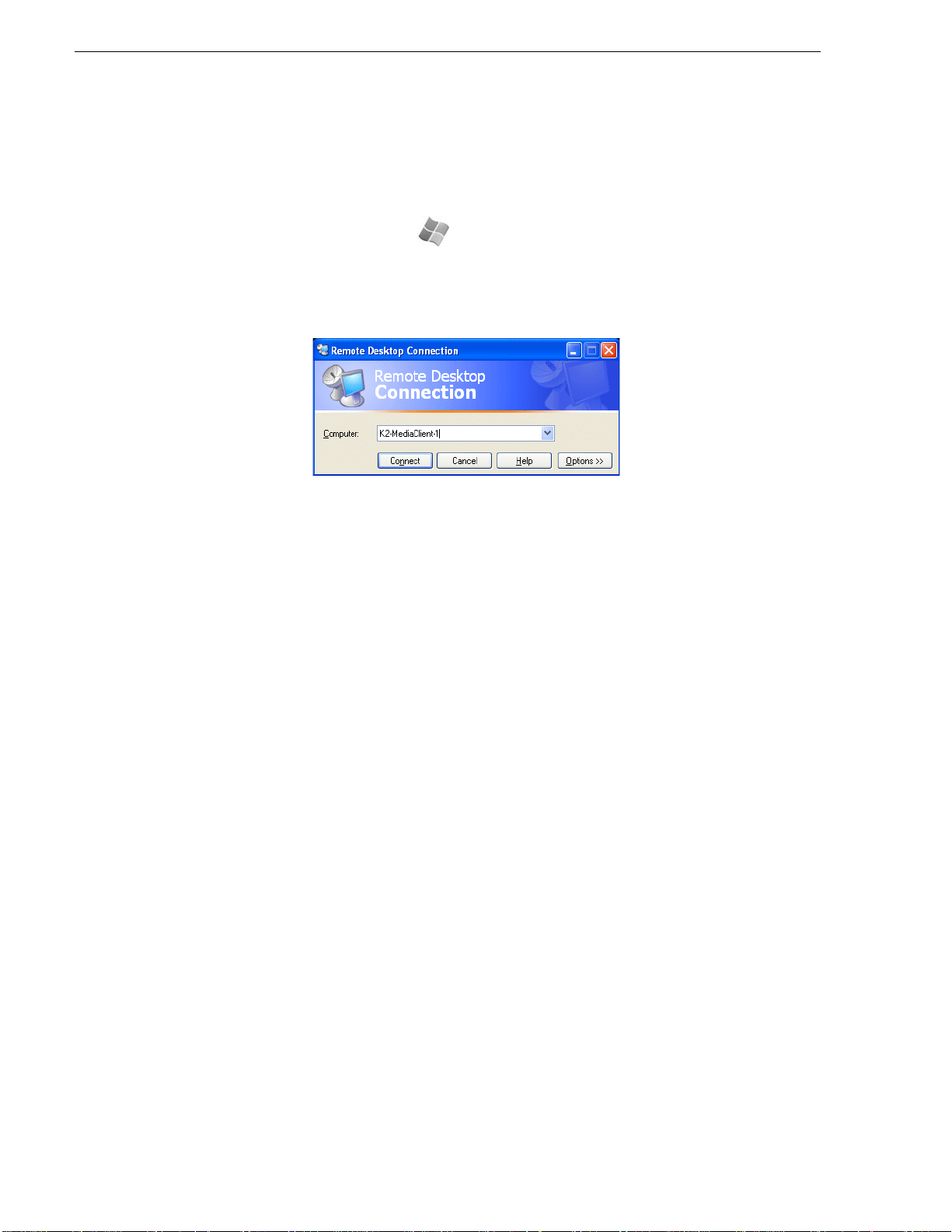
Chapter 2 Using K2 Media Client system tools
To access the Remote Desktop Connection, follow these steps:
1. Click the
—or—
Press the Windows key on the keyboard.
2. Select
Remote Desktop dialog box displays.
3. Enter the name or IP address of the K2 system and click the
Alternately, you can click the down arrow of the text box and browse for the K2
system or select a previously entered computer.
Start button on the Windows task bar
Programs | Accessories | Communi cations | Remote Desktop Connecti on. The
Connect button.
SiteConfig - a ProductFrame application
ProductFrame is a in tegra ted pla tfor m of t ools an d produc t dist ri butio n proce sses f or
system installation and configuration. SiteConfig is a ProductFrame application and
it is the recommended tool for network configuration and software deployment.
You can use SiteConfig as a stand-alone tool for planning and system design, even
before you have any devices installed or cabled. You can define networks, IP
addresses, hostnames, int erfaces, and other network parameters. You can add devices,
group devices, and modify device roles in the system.
As you install and commission systems, SiteConfig runs on the control point PC. It
discovers devices, configures their network settings, and manages host files.
SiteConfig also manages software installations and upgrades and provides a unified
software package for deployment across multi-product systems.
You should use SiteConfig for network configuration and software deployment at
installation and throughout the life of the system in your facility. This enforces
consistent policy and a llows Site Config t o cap ture change s, which make s the sys tem
easier to maintain and aids in troubleshooting should a problem arise.
To open SiteConfig, do the following:
1. On the control point PC open the SiteConfig shortcut on the desktop.
The SiteConfig application opens.
48 K2 Media Client System Guide June 9, 2009
Page 49

SiteConfig - a ProductFrame application
Select a
module...
And a tree
view tab...
Then select an item
in the tree view...
To display list
view details...
SiteConfig displays information from a system description file, which is an XML
file.
SiteConfig has different modules that correspond to a system’s life-cycle phases,
such as network configuration and software deployment. You can expand nodes
and select element s in the t ree view and the list vi ew to view an d modify networ ks,
systems, individual devices, software deployment, and configuration settings.
June 9, 2009 K2 Media Client System Guide 49
Page 50

Chapter 2 Using K2 Media Client system tools
50 K2 Media Client System Guide June 9, 2009
Page 51

Chapter 3
System connections and configuration
This chapter applies to “online” K2 systems, which includes stand-alone K2 Media
Clients and K2 Storage Syste ms with c onnect ed shar ed st orage K2 Medi a Clie nts. I n
contrast, the Nearline K2 Storage System is considered an “offline” K2 system. Refer
to the K2 Storage System Instruction Manual for information about Nearline K2
Storage Systems.
This chapter contains the following topics:
• “Network connections and configuration”
• “Teaming Ethernet ports on internal storage models”
• “Modifying network settings”
• “Using FTP for file transfer”
• “Using the HotBin service”
• “Using the Pathfire capture service”
• “Using the DG capture service”
• “Using the XML Import capture service”
• “Licensing K2 capture service software”
• “Pinnacle support”
• “Connecting RS-422”
• “Connecting GPI”
June 9, 2009 K2 Media Client System Guide 51
Page 52

Chapter 3 System connections and configuration
SD-00 and SDA-00 GigE network connections
Network connections and configurati on
Refer to the following list of procedures, then perform the ones required to set up the
Gigabit (1GBaseT) Ethernet network for your application:
• “Cable requirements”
Lists the requirements for Ethernet cables .
• “About Ethernet ports and teaming”
Explains the default configuration of the Ethernet ports.
• “Connecting the Ethernet network cabling”
Shows how to connect the K2 Media Client to an Ethernet network using the
standard 1GBaseT ports.
• “Data and streamin g for K2 systems”
Contains instructions for configuring the network connection to support the
following:
• Remote control of the K2 Media Client with AppCen ter or with remote protocol
applications over Ethernet.
• Streaming media transfers between K2 systems.
• Standard data network capability
Cable requirements
For making Ethernet connections, cabling must meet the following requirements:
• Use CAT5e or CAT6 cables. The maximum cable length is 50 meters for CAT5e
and 100 meters for CAT6.
About Ethernet ports and teaming
The K2 Media Client can have four Gigabit Ethernet ports: two on the motherboard
and two on the Network Interface Card. The location of the ports varies on the
different K2 Media Clients models, as in the following illustration:
UNUSED UNUSED
PushPush
HD-00 GigE network connections
UNUSED UNUSED
LTC OUT
D
UNUSEDUNUSED
LTC I N
PushPush
Port 2
Port 1
Onboard ports NIC ports
• On internal storage models, ports are not teamed at the factory. They are
independent ports, e ach wit h the same co nfi guratio n. If you chose t o tea m ports to
provide redundancy, do so only as instructed in “Teaming Ethernet ports on
52 K2 Media Client System Guide June 9, 2009
Port 4Port 3
Port 1
Port 2
Onboard ports NIC ports
Port 4Port 3
Page 53

Connecting the Ethernet network cabling
internal storage models” on page 63.
• On shared storage (iSCSI SAN) models, the first port on the motherboard (Port 1)
and the first port on the Gigab it Ethernet card (Po rt 3) are config ured at the fact ory
as a teamed pair. This is the Contro l Team. The teamed pair appears to th e network
as a single adapter with one IP address. Do not modify this teamin g configura tion.
If you need to res et te amin g to fa ctory speci ficat io ns, ref er t o the K2 Me dia Client
Service Manual.
On shared (iSCSI SAN) stor age mo dels, the s econd p ort on t he mo therb oard (p ort
2) and the second port on the Gigabit Ethernet card (port 4) must be independent
ports (unteamed). These are the media ports, used for iSCSI traffic only. Refer to
Chapter 8, Shared Storage and to the K2 Storage System Instruction Manual for
more information about the media ports.
• On direct-connect storage models, the Fibre Channel board replaces the Gigabit
Ethernet card, so t he only Et hernet p orts are those on the mothe rboard. The re is no
teaming on a direct-connect K2 Media Client.
Connecting the Ethernet network cabling
This section is divided into two parts:
“Connecting the network cabling for stand-alone K2 Media Clients” on page 53
“Connecting the network cabling for K2 Media Clients with shared storage” on
page 53
Connecting the network cabling for stand-alone K2 Media Clients
On a K2 Media Client with internal storage and on a K2 Media Client with
direct-connect storage, port 1 is the control port, used to transmit command
information, AMP protocols, etc. Connect the control network to port 1.
Port 2 is used for FTP/streaming transfers. Connect the FTP/streaming network to
port 2. Refer to “Usi ng FTP fo r file transfer” on page 77 for more information about
the FTP/streaming network.
Do not use ports 3 and 4 on a K2 Media Client with internal storage, except if you
have teamed your ports. Refer to “Tea ming Ethernet ports on interna l storage models”
on page 63.
Connecting the network cabling for K2 Media Clients with shared storage
In the K2 Media Client with shared storage, ports 1 and 3 are the control team, used
to transmit control information, while port 2 and port 4 (not teamed) are used for
iSCSI traffic, which is the recording or playing of media.
Control Network
For a non-redundant K2 Storage System, make a control connection from the GigE
switch to port 1.
For a redundant K2 Storage System, make a control connection from the “A” GigE
switch to port 1 and a control connection from the “B” GigE switch to port 3.
June 9, 2009 K2 Media Client System Guide 53
Page 54

Chapter 3 System connections and configuration
Media/iSCSI network
For a non-redundant K2 St orage System, connect th e medi a/ iSCSI network to port 2.
For a redundant K2 Stor age System, connect the “A” medi a/ iSCSI network to port 2
and the “B” media/iSCSI network to port 4.
Refer to the K2 Storage System Instruction Manual for more information.
Data and streaming for K2 systems
After making 1GBaseT network connections as described in “Connecting the
Ethernet network cabling” on page 53, use the following procedure to configure the
network settings. Once configured, you can perform the following tasks:
• General networking tasks such as file sharing and mapping network drives.
• Remote control an d configu ration of the K2 Me dia Client using App Center from a
Control Point PC.
• Remote control of the K2 Media Client using devices and applications software
developed for the K2 Media Client that use industry standard remote control
protocols over Ethernet.
• Stream media transfers between K2 systems and other supported Grass Valley
systems. Streaming t ransfers al low loading an d playing a clip before the transfe r is
complete.
Setting up the K2 system for FTP/streaming transfer has the following network
requirements:
• For stand-alone K2 Me dia Clients, the K2 Media C lient itself is the source/
destination for FTP/s tr eami ng t ra nsf er s. FTP/ st re aming traffic uses the FT P GigE
port on the K2 Media Client.
• For K2 Media Clients with shared storage on a K2 Storage System, a K2 Media
Server is the source/de stination for FTP/ streaming transf ers. FTP/streaming traffic
uses the FTP GigE port on the K2 Media Server. No transfers go to/from the shared
storage K2 Media Client directly.
• Some kind of name re solution process must be followed. You must e ither reference
host names through hosts files located on each networked device or edit the DNS
entries. To edit the DNS entries, see your network administrator. To set up host
files, see “Connecting the Ethernet network cabling” on page 53.
• The host name of all peer K2 systems, M-Series iVDRs, and Profile XP systems
must be added to a Remote host regis try us ing the K2 Media Cli ent Conf igura tion
Manager.
• To import to or export from a K2 system, both the source and destination need to
be in the same domain.
This procedure guides you to relevant settings, but does not instruct you on the
specific settin gs required for your network. It i s assumed that you understand Ether net
networks in general and your particular network needs and that you can apply that
understanding to make the required settings using standard Windows procedures. If
you need help with these procedures, contact your network administrator.
54 K2 Media Client System Guide June 9, 2009
Page 55

Configure Windows network settings
!
Topics in this section in clude the following:
• “Configure Windows network settings for a stand-alone K2 Media Client” on
page 55
• “Configure Windows network settings for K2 Media Clients with shared
storage” on page 57
• “Set up hosts files” on page 58
• “Add network hosts names for streaming” on page 61
CAUTION: The K2 Media Client is not a general purpose Windows
workstation. The Windows configuration on the K2 system has been
specifically set for use as a real time device. To avoid partial or total
system failure, do not modify any operating system settings unless
approved by Grass Valley, including but not limited to the following:
— Do not use the User Manager
— Do not use t he Disk Admin istrator
— Do not load any third party software
— Do not install any Windows updates other than “High Priority
Updates” without contacting Grass Valley Product Support. (See
“Configuring K2 security” on page 134.)
Configure Windows network settings
Configure Windows network settings for a stand-alone K2 Media Client
The internal storage K2 Media Cl ient and th e direct-connect K2 Media Clien t ship
from the factory DHCP c onfigure d. If your c ontrol n etwork has DHCP/DNS and you
are satisfied to use the factory default K2 Media Client host name (which is the serial
number), then no local configuration of the control connection is required.
There are special name re solution requirements for t he FTP/streaming network. If you
require FTP/streaming transfers for the stand-alone K2 Media Client, refer to
“Streaming video between K2 systems” on page 58 to determine your method of
providing this name resolution and the configuration required.
If the Windows network settings for the stand-alone K2 Media Client need to be
configured, you must have Windows administrator security privileges on the K2
Media Client.
To configure network settings on a stand-alone K2 Media Client, do the following:
1. Access the Windows desktop on the K2 system. You can do this locally with a
connected keyboard, mouse, and monitor or remotely via the Windows Remote
Desktop Connection.
2. Open the Network Connections dialog box:
• In the Windows Classic view, select
• In the Windows XP view, select Start | Control Panel | Network Connections
Start | Settings | Network Connections
3. Continue with standard Windows procedures to configure the TCP/IP protocol
properties. You can set up the network using DHCP, DNS, WINS, or other
standard networking mechanisms.
June 9, 2009 K2 Media Client System Guide 55
Page 56

Chapter 3 System connections and configuration
!
NOTE: On small networks or networks with certain security policies a DHCP
server or domain name server (DNS) might not be available. In this case you can
set up a static IP address and create a Host file on each K2 system. The Host file
specifies a device name for each IP address used on the network. Refer to the
Windows documentation or your network administrator for more information.
4. Configure the control connection on the stand-alone K2 Media Client as follows:
• On a system with the factory default network configurations, configure the
network connection with the following name:
Control Connection #1
This is GigE port 1 on the rear panel.
• If you have teamed your ports, configure the network connection with the
following name:
Control Team
This is GigE ports 1 and 3 on the rear panel. Refer to “Teaming Eth ern et por ts
on internal storage models” on page 63 for more information about teaming.
CAUTION: Under no circumstances should you modify the loopback
adapter. The loopback IP address is 192.168.200.200. Keep that IP
address reserved on your network. Don’t assign it to any other
device.(If this causes conflicts with your exis ting network, cons ult your
Grass Valley representati ve .)
5. Confi gure the FTP/s treaming con nection (i f needed) on t he stand-a lone K2 Media
Client. This connection must ha ve an IP address that is on a di ff er ent subnet from
the control connection. Configure as follows:
• On a system with the factory default network configurations, configure the
network connection with the following name:
Media Connection #1
This is GigE port 2 on the rear panel.
• If you have teamed your ports, configure the network connection with the
following name:
FTP Team
This is GigE ports 2 and 4 on the rear panel. Refer to “Teaming Eth ern et por ts
on internal storage models” on page 63 for more information about teaming.
6. If prompted, shutdown and restart Windows.
7. If y ou are g oing t o FTP/st ream vid eo bet ween K2 systems , proce ed to “Streaming
video between K2 systems”; otherwise, the K2 system is ready for standard data
networking tasks.
56 K2 Media Client System Guide June 9, 2009
Page 57

Configure Windows network settings
Configure Windows network settings for K2 Media Clients with shared storage
The only network configur at ion that you must do on an exte rna l ( sha red) storage K2
Media Client is fo r the control c onnection. Once the control con nection is conf igured,
you use it to connect to the K2 Media Client from the control point PC and then use
the K2 System Configuration application to do the remainder of the network
configuration.
The K2 Media Client ships from th e factory DHCP configur ed. If the control netwo rk
you are using with your K2 Storage System has DHCP/DNS a nd yo u are satisfied to
use the factory defaul t K2 Media Client host na me (whi ch is the s erial number) , then
no local configuration of the control connection is required.
If the control connection needs to be configured, you must have Windows
administrator security privileges on the K2 Media Client.
To configure the control connection on the shared storage K2 Media Client, do the
following:
1. Access the Windows desktop on the K2 system. You can do this locally with a
connected keyboard, mouse, and monitor or remotely via the Windows Remote
Desktop Connection.
2. Open the Network Connections dialog box:
• In the Windows Classic view, select
Start | Settings | Network Connections
• In the Windows XP view, select Start | Control Panel | Network Connections
3. Continue with standard Windows procedures to configure the TCP/IP protocol
properties. You have the following options to set up the control network:
• You can set up the network using DHCP, DNS, WINS, or other standard
networking mechanisms.
• You can use host tables f or name resolution. There are special name resol ution
requirements for the FTP/ stream ing network, s o if you decide to use host ta bles
for the control network, you sho uld be aware of these require ments. Refer to the
“Streaming video betwee n K2 systems” on page 58 and the K2 Storage Syst em
Instruction Manual for a complete discussion of host tables.
4. Configure the control connection on the shared storage K2 Media Client. In the
Network Connections window, it is the connection with the following name:
Control Team
This is GigE ports 1 and 3 on the rear panel.
Do not attempt to configure connect ions named Control Conne ction #1 or Control
Connection #2, as these have been combined in the Control Team.
NOTE: Be sure to configure only the connection that is labelled “Control Team”
in the Name column. Under no circumstances should you modify the loopback
adapter. The loopback IP address is 192.168.200.200. Keep that IP address reserved
on your network. Don’t assign it to a ny other devi ce. (If this causes conflicts with
your existing networ k, consult your Grass Valley representative.)
5. Do not configure connections named Media Connection #1 or Media Connection
#2, as these are reserved for t he sh ared stor age med ia (iSCSI) ne twork an d should
June 9, 2009 K2 Media Client System Guide 57
Page 58

Chapter 3 System connections and configuration
only be configured using the K2 System Configuration appli cation. Refer to the K2
Storage System Instruction Manual.
6. If prompted, shutdown and restart Windows.
7. You must add the shared stor age K2 Media Client to th e K2 Storage System. Refer
to Chapter 8, Shared Storage.
8. If yo u are going to st ream video betwe en K2 systems, proceed to “Streaming video
between K2 systems”.
Streaming video between K2 systems
It is required that FTP/streaming traffic be on a separate subnet from control traffic
and, in the case of a K2 Storage System with shared storage K2 Media Clients,
separate from media (iSCSI) traffic. To reserve bandwidth and keep FTP/streaming
traffic routed to dedicated ports, IP addresses for FTP/streaming ports must have
double name resolution such that hostnames are appended with the “_he0” suffix.
You can use host tables or another mechanism, such as DNS, to provide the name
resolution. This directs the streaming traffic to the correct port.
In most K2 systems, network name resolution is provided by host tables. The
following procedure describes how to set up hosts tables to provide name resolution
for both the control network and the FTP/streaming network. If you are using other
mechanisms for name resolution, use the host table examples here to guide you. For
shared storage K2 Media Cl ients, also refer t o the K2 Stor age Instr uction Manual for
a discussion of host tables.
Set up hosts files
Set up a hos t s file located in c:\WINDOWS\system32\drivers\etc\hosts on each K2
system. If you include the names and ad dre sses of all th e syste ms on all the netwo rk,
then you can copy this information to all the machines instead of entering it in the
hosts file on each machine.
To provide the required name resolution for the FTP/streaming network, in the host
file each system that is a transfer source/dest ination has its host name listed twice:
once for the contr ol network and once for the FT P/streaming ne twork. The host name
for the streaming network has the extension “_he0” after the name. The K2 systems
use this information to keep the FTP/streaming traffic separate from the control
traffic.
For FTP transfers to/fro m a K2 Storage System (SAN), transfers go to/f rom K2 Media
Servers that have the role of FTP server. No transfers go directly to/from the shared
storage K2 Media Clients th at are on the K2 Storage Syst em. So in the hosts fi le, you
must add the “he_0” extension to a K2 Media Server hostname and associate that
hostname with the K2 Media Server’s FTP/streaming network IP address.
On optional step is to provide “err or correction” aliasing for shared storage (SAN) K2
Media Clients as well. For each shared storage K2 Media Client, add the “_he0”
extension to the hostname but then associate that hostname with the K2 Media
Server’s FTP/streaming network IP address, not the K2 Media Client’s IP address.
Aliasing K2 Media Cli ent host names in t his way would not be requi red if the tra nsfer
source/destinati on was a lways c orrectl y spec ifie d as t he K2 Med ia Ser ver. Howe ver,
a common mistake is to attempt a transfer in which the source/destination is
incorrectly s pecified a s the K2 M edia Client . This “err or correc tion” host file ali asing
58 K2 Media Client System Guide June 9, 2009
Page 59

Streaming video between K2 systems
redirects to the K2 Media Server, which is the correct transfer source/destination. Use
this technique with caution , as it can ma sk transf er proble ms and hamper you r abil ity
to troubleshoot and find the root cause.
To see an example of a K2 Media Client configuration setup and hosts file, refer to
the “Sample K2 Media Client configuration and hosts file” on page 60. Otherwise,
proceed with the following steps to set up your hosts file.
On each K2 system, set up the hosts file as follows:
1. Open the following file using Notepad or some other text editor.
c:\WINDOWS\system32\drivers\etc\hosts
2. Enter text in two lines for each K2 system that is a transfer source/destination.
a. Type the IP address for the con trol networ k, then use th e TAB key or Space bar
to insert a few spaces.
b. Type the machine name, such as
K2-MediaClient. This sets up the host file for
resolving the machine name on th e contro l network . The machin e name cannot
have any spaces in it.
c. On the next line, type the IP a ddress for the FTP/st reaming network, then us e the
TAB key or Space bar to insert a few spaces.
d. Type the machine name followed by the characters “_he0”. Be sure to use the
zero character, not the letter ‘o’. Refer to the following example:
10.16.42.10 K2-MediaClient
10.0.0.10 K2-MediaClient_he0
3. If you choos e to add the “error correction” aliasing to the FTP/ streaming network
line for a K2 Media Server, do so as in the following example:
10.0.0.22 K2-MediaServer-1_he0 K2-Medi aClient-1_he0 K2-Medi aClient-2_he0
4. For s yst ems that are n ot a tr an sfer s ource/ desti nati on, the sec ond li ne (for the FTP /
streaming network) is not required.
5. If t here are UIM systems on the FTP/strea ming network, make su re you follow t he
UIM naming conventions. Refer to the UIM Instruction Manual.
6. Once you have added the host names for the all the systems on the networks for
which the host file provides name resolution, sav e the fi le an d exit the text editor.
7. Copy the new hosts file onto all the other machines to save you editing it again.
8. Proceed to “Add network hosts names for streaming”.
June 9, 2009 K2 Media Client System Guide 59
Page 60

Chapter 3 System connections and configuration
K2-Client
(internal storage)
Stand-alone
NewsEdit1
(not shared storage)
SAN_XP1
SAN_UIM1
K2-Client-2
(shared storage)
K2-Media Server-1
Control Point PC
10.0.0.22
Other 3rd party devices
Command/Control network
FTP/Streaming network
10.16.42.10
10.0.0.10
10.16.42.102
10.16.42.60
10.0.0.60
Note: The two media GigE ports are not used for
FTP/streaming. They are used for media (iSCSI)
networks only
10.16.42.22
10.16.42.31
10.16.42.32
10.0.0.32
10.16.42.23
K2-Client-1
(shared storage)
10.16.42.101
Sample K2 Media Client configuration and hosts file
The following diagram illustrates one possible configuration setup, with both a K2
Media Client with inter nal storage and a K2 Media Client with shar ed storage, as wel l
as other Gr ass Valley systems.
The following example shows the contents of a default Windows hosts file with
# Copyright (c) 1993-1995 Microsoft Corp.
# This is a sample HOSTS file used by Microsoft TCP/IP for Windows.
# This file contains the mappings of IP addresses to host names. Each
# entry should be kept on an individual line. The IP address should
new lines added that matc h the IP addresse s and host names in the pre vious sample
diagram.
All lines beginning with a # are comments and can be ignored or deleted.
# be placed in the first column followed by the corresponding host name.
# The IP address and the host name should be separated by at least one
# space.
# Additionally, comments (such as these) may be inserted on individual
# lines or following the machine name denoted by a '#' symbol.
#
60 K2 Media Client System Guide June 9, 2009
Page 61

Streaming video between K2 systems
# For example:
# 102.54.94.97 rhino.acme.com # source server
# 38.25.63.10 x.acme.com # x client host
127.0.0.1 localhost
10.16.42.10 K2-MediaClient
10.0.0.10 K2-MediaClient_he0
10.16.42.101 K2-MediaClient-1
10.16.42.102 K2-MediaClient-2
10.16.42.22 K2-MediaServer-1
10.0.0.22 K2-MediaServer-1_he0 K2-MediaClient-1_he0 K2-MediaClient-2_he0
10.16.42.23 ControlPointPC
10.16.42.60 NewsEdit1
10.0.0.60 NewsEdit1_he0
10.16.42.31 SAN_XP1
10.0.0.32 SAN_XP1_he0 SAN_UIM1_he0
10.16.42.32 SAN_UIM1
Add network hosts names for streaming
You must add the host names of all peer K2 systems on the network that support
streaming transfers. Adding host names is required to allow selection of networked
K2 systems in the AppCenter user interface and to provide a successful network
connection for streaming. The host names added will appear in the “Import” and
“Send to” dialog boxes.
NOTE: By default, the K2 system host name is the same as the Wi ndows comput er
name. To determine the K2 s yst em c omput er name, right-click K2 Media Client or
K2 Media Server (My Computer) on the Windows desktop, then properties. Select
the Network Identification tab and look for the “Full computer name”.
To add network host names:
1. Open AppCenter for the K2 Media Client.
2. In AppCenter toolbar, select
3. Sele ct the
Remote tab.
System, then choose Configuration.
The Remote Settings dialog box displays, showing any network host names that
have been added.
June 9, 2009 K2 Media Client System Guide 61
Page 62

Chapter 3 System connections and configuration
4. Select Add, to open the Add Host dialog box, then do the following:
a. Select the Host name field, then enter the computer name of a peer K2 system.
Make sure to enter the exa ct computer name. Any differences wil l result in being
unable to con nect to the K 2 system.
b. If y ou are usi ng VDCP remote prot ocol to pe rform video ne twork tra nsfers, us e
the following steps to a dd a uniqu e Control ler I D for eac h host. Ot herwise , you
can ignore this step and proceed to the next step.
- Select controller id field.
- Enter the controller ID of the K2 system, then select
OK. Use a number
between 1 and 255 that is not assigned to any other K2 system.
c. Select
OK in the Add Host dialog box.
5. Repeat the previous step for the remaining K2 systems.
6. In the Configuration dialog box, select
OK to save settings.
Once the host names a re added, the K2 system is ready fo r streaming operat ion. For
information on transfer compatibility and supported formats, refer to Appendix B,
Specifications. For procedures on transfer ring me dia , refe r to the K2 Media Client
User Guide.
62 K2 Media Client System Guide June 9, 2009
Page 63

Teaming Ethernet ports on internal storage models
NOTE: If you have trouble, try using the ping utility in the Windows command
prompt using either the IP address or host name. Troubleshoot as needed. Also,
refer to the K2 Media Client Service Manual for tr oubleshooting procedures.
Teaming Ethernet ports on internal storage models
When you receive an interna l storage K2 Media Client from th e factory, th e Ethernet
ports are independent ports, each with the same configuratio n. Ports are not teamed at
the factory. However, if your K2 Media Client has four Ethernet ports, you have the
option of teaming the Ethernet ports to provide redundancy. Do not team Ethernet
ports on K2 Media Clients t hat have just t wo Ether net por ts, suc h as a di rect- connec t
storage K2 Media Client. Cons ul t your system design or your net work a dministrator
to determine the level of redundancy applicable to the internal storage K2 Media
Client.
NOTE: Do not use these procedures on an shared stor age K2 Media Client. There
is a required teaming configuration on shared storage K2 Media Clients, which
must not be changed. If you must restore the requir ed teaming on an shared storag e
K2 Media Client, refer to the K2 Media Client Service Manual.
If you choose to team the Ethernet ports on an internal storage K2 Media Client, do
so only as instructed in the following procedures.
• “Identify adapters”
• “Create the Control Team”
• “Create the FTP Team”
• “Name teams”
• “Reorder adapters”
Identify adapters
NOTE: The K2 Media Client is configured at the fact ory with a loopback adapter.
Do not modify this adapter. Refer to “Modifying network settings” on page 77.
Before attempting to team Eth ernet po rts, it is cr itical that you corr ectly asso ciate the
software names of the adapters with the physical ports. In some cases previous
configuration changes can cause the software names to change from their factory
default names, which can make this association confusing. Use the following
procedure to verify software names and ports:
1. Access the Windows desktop on the K2 system. You can do this locally with a
connected keyboard, mouse, and monitor or remotely via the Windows Remote
Desktop Connection.
2. Open Device Manager as follows:
a. On the Windows desktop, right-cli ck
Manage. The Computer Management window opens.
June 9, 2009 K2 Media Client System Guide 63
K2 Media Client (My Computer) and selec t
Page 64

Chapter 3 System connections and configuration
b. In the left pane select Dev ice M ana ger . De vic e Manager opens in the right pa ne.
3. In Device Manager, verify that adapter names are the correct default names as
follows:
a. Expand
Network Adapters.
b. If a Type I motherb oard, verify that there are four adapters listed, na med as
follows:
- Intel® PRO/1000 MT Dual Port Server Adapter
- Intel® PRO/1000 MT Dual Port Server Adapter #2
- Intel® PRO/1000 MT Dual Port Server Adapter #3
- Intel® PRO/1000 MT Dual Port Server Adapter #4
c. If a Type II motherboard, verify that there are four adapters listed, named as
follows:
- Intel® PRO/1000 EB Network Connection with I/O Acceleration
- Intel® PRO/1000 EB Network Connection with I/O Acceleration #2
- Intel® PRO/1000 MT Dual Port Server Adapter
- Intel® PRO/1000 MT Dual Port Server Adapter #2
Sometimes adapter names change due to PNP device removal and re-creation.
If you are having this problem, remove all network devi ces, the n reboot and let
Windows PNP enumerate netw ork adapter s. The def ault net work names s hould
reappear numbered correctly. If the numbering is still incorrect, shut down the
K2 Media Client, remove the dual Ethernet card, then start up the K2 Media
Client. This forces the system to scan the motherboard ports first and enumerate
properly. Then shutdown the K2 Media Client, replace the dual Ethernet card,
and start up the K2 Media Client. This time the dual Ethernet card is scanned
and enumerated after the motherboard ports.
64 K2 Media Client System Guide June 9, 2009
Page 65

Identify adapters
4. For ea ch adapte r nam e shown, ve rify that t he adapte r nam e is map ped c orrec tly t o
a physical port, as follows:
a. Under Network adapters, right-click an adapter and select
Properties dialog box opens.
Properties. The
5. Sele ct the
Link tab and then click Identify Adapter. The Identi fy Adapter dia log box
opens.
6. Click
Start.
7. Verif y that the LED i s blinki ng next to t he physica l network p ort corresp onding to
June 9, 2009 K2 Media Client System Guide 65
Page 66

Chapter 3 System connections and configuration
that adapter software name, as follows:
Software adapter name
Type I Mothe r b oa r d
…MT Dual Port Server Adapter …EB Network Connection… 1st (left) port on the motherboard
…MT Dual Port Server Adapter #2 …EB Network Connection…#2 2nd (right) port on the mother board
…MT Dual Port Server Adapter #3 …MT Dual Port Server Adapter 1st (upper) port on the dual Ethernet
…MT Dual Port Server Adapter #4 …MT Dual Port Server Adapter #2 2nd (lower) port on the dual
Software adapter name
Type II Motherboard
Physical port (as viewed facing
the rear panel)
adapter
Ethernet adapter
External storage K2 Media Clients with the optional Fibre Channel card installed
do not have the dual Ethernet adapters.
8. Continue with the next procedure “Create the Control Team”.
Create the Control Team
The goal of teaming is to create two teams, one for the control network and one for
the FTP/streaming network . The teamin g shoul d be s et up such that the f irst physi cal
port on the motherboard and the first physical port on the dual Ethernet adapter are
teamed for control. The second physical port on the motherboard and the second
physical port on the dual Ethernet adapter are teamed for FTP.
Prior to K2 system software rele ase 3.2.5x i n the Fall of 2007, there was a bug in the
teaming software for which the work around required creating a team named “DO
NOT USE”. With release 3.2.5x., driv ers were updated and the bug was fixed. The fix
is available on K2 Media Clients shipping after the release of 3.2.5x. Earlier K2
Media Clients retain the same drivers, even if the system software is updated, and so
must use continue to use the “DO NOT USE” work around if teaming must be
configured. Use the procedure appropriate for your K2 Media Client.
Create the Control Team on systems shipping before 3.2.5x
Use this procedure if th e K2 Media Cli ent shipped from Grass Vall ey prior t o release
3.2.5x in the Fall of 2007.
1. In Devi ce Manager, right-clic k
…MT Dual Port Server Adapte r and select Properties.
The Properties dialog box opens.
2. Sele ct the
66 K2 Media Client System Guide June 9, 2009
Teaming tab.
Page 67

Create the Control Team
3. Select Team with other adapters, then click New Team. The New Team Wizard
opens.
4. Enter DO NOT USE.
You enter this name because there is a bug in the teaming software that creates a
“phantom” entry with this name, however that entry is not usable. Continue with
this procedure to work around the bug.
Click
Next.
June 9, 2009 K2 Media Client System Guide 67
Page 68

Chapter 3 System connections and configuration
5. Select the check box for …Adapter and …Adapter #3. Click Next.
6. Select
7. Click
Switch Fault Tolerance. Click Next.
Finish and wait a few seconds for the adapters to be teamed.
8. Open the Modify Team dialog box as follows:
a. In Device Manager | Network Adapters, right-click
Services Virtual Adapters #2
adapter) and select
b. Sele ct the
68 K2 Media Client System Guide June 9, 2009
Settings tab.
Properties. The Properties dialog box opens.
(make sure it is the adapter identified as a Virtual
Intel® Advanced Network
Page 69

c. Click Modify Team. A dialog box opens.
Create the Control Team
9. On the
a. Select the top entr y, which is
b. Select
10.Click
11.Click
Adapters tab, do the following:
Intel® PRO/1000 MT Dual Port Server Adapter (Type
I MB) or
MB), and click
PRO/1000 MT Dual Port Server Adapter
Intel® PRO/1000 EB Network Co nnec tion w ith I/O Ac cel eratio n (Ty pe II
Set Primary.
Intel® PRO/1000 MT Dual Port Server Adapter #3 (Type I MB) or Intel®
(Type II MB) and click Set Secondary.
Name tab and rename to Control Team.
OK and OK and to close dialog boxes.
Continue with “Create the FTP Team” on page 72.
Create the Control Team on systems shipping after 3.2.5x
Use this procedure if the K2 Media Client shipped from Grass Valley after release
3.2.5x in the Fall of 2007.
1. In Devi ce Manager, right-click
…MT Dual Port Server Adapter and select Properties.
The Properties dialog box opens.
2. Sele ct the
Teaming tab.
June 9, 2009 K2 Media Client System Guide 69
Page 70

Chapter 3 System connections and configuration
3. Select Team with other adapters, then click New Team. The New Team Wizard
opens.
4. Enter Control Team.
Click
Next.
70 K2 Media Client System Guide June 9, 2009
Page 71

5. Select the check box for …Adapter and …Adapter #3. Click Next.
Create the Control Team
6. Select
7. Click
Switch Fault Tolerance. Click Next.
Finish and wait a few seconds for the adapters to be teamed.
8. Open the Modify Team dialog box as follows:
a. In Device Manager | Network Adapters, right-click
Services Virtual Adapters #2
adapter) and select
b. Sele ct the
June 9, 2009 K2 Media Client System Guide 71
Settings tab.
Properties. The Properties dialog box opens.
(make sure it is the adapter identified as a Virtual
Intel® Advanced Network
Page 72

Chapter 3 System connections and configuration
c. Click Modify Team. A dialog box opens.
9. On the
Adapters tab, do the following:
a. Select the top entr y, which is
I MB) or
Intel® PRO/1000 EB Network Connection with I/O Acce lerati on (Type II
MB), and click
b. Select
10.Click
Intel® PRO/1000 MT Dual Port Server Adapter #3 (Type I MB) or Intel®
PRO/1000 MT Dual Port Server Adapter
OK and OK and to close dialog boxes.
Continue with the next procedure “Create the FTP Team”.
Create the FTP Team
1. In Device Manager, right-click …MT Dual Port Server Adapter #2 (Type I MB) or
…EB Network Connection with I/O Acceleration #2 (Type II MB) and select
Properties. The Properties dialog box opens.
2. Sele ct the
Teaming tab.
Intel® PRO/1000 MT Du al Port Server Adapter (Type
Set Primary.
(Type II MB) and click Set Secondary.
72 K2 Media Client System Guide June 9, 2009
Page 73

Create the FTP Team
3. Select Team with other adapters, then click New Team. The New Team Wizard
opens.
4. Enter FTP Team. (Some earlier systems used the name “Media Team”.) Click
Next.
June 9, 2009 K2 Media Client System Guide 73
Page 74

Chapter 3 System connections and configuration
5. Select the check box for …Adapter #2 and …Adapter #4. Click Next.
6. Select
7. Click
Switch Fault Tolerance. Click Next.
Finish and wait a few seconds for the adapters to be teamed.
8. Open the Modify Team dialog box as follows:
a. In Device Manager | Network Adap ters, ri ght-clic k
Properties. The Properties dialog box opens.
b. Sele ct the
c. Click
74 K2 Media Client System Guide June 9, 2009
Settings tab.
Modify Team. A dialog box opens.
TEAM: FTP TEAM and select
Page 75
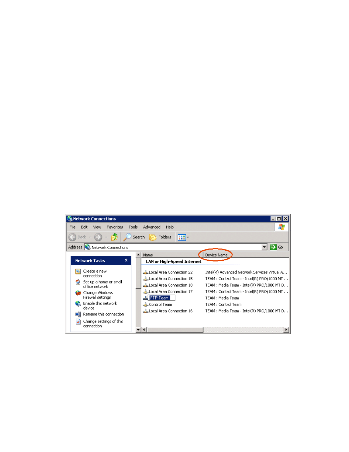
9. On the Adapters tab, do the following:
Name teams
a. Select the top entry, which is
(Type I MB) or In tel® PRO/1000 EB Netw ork Connec tion with I/O Acc eleration #2
(Type II MB), and click Set Primary.
b. Select the bottom entry, which is
#4
and click
10.Click
11.Click
12.Restart the K2 Media Client.
Continue with the next procedure “Name teams”.
Name teams
This procedure ap pli es on ly to internal storage K2 Media Clients on which you have
created a Control Team and a FTP Team, as instructed in previous procedures.
1. On the Windo ws deskt op rig ht-cl ick
Network Connections window opens.
Intel® PRO/1000 MT Dual Port Server Adapter #2
Intel® PRO/1000 MT Dual Port Server Adapter
(Type I MB) or Intel® PRO/1000 MT Dual Port Serve r Adapter #2 (Type II MB)
Set Secondary.
Name tab and rename to FTP Team, if not already named.
OK and OK and to close dialog boxes.
My Network Places and selec t Properties. The
2. Ident ify the adapter that i n the “Device Name” column is labeled “TEAM : Control
Team”. Rename the adapter follows:
a. Click the Adapter Name.
b. Select
File | Rename to enter rename mode.
c. Type Control Team.
3. Identify the adapter that in the “Device Name” column is labeled “TEAM : FTP
Team”. Rename the adapter follows:
June 9, 2009 K2 Media Client System Guide 75
Page 76

Chapter 3 System connections and configuration
a. Click the Adapter Name.
b. Select
File | Rename to enter rename mode.
c. Type FTP Team.
4. Ensure that eight entries are named as follows in Network Properties:
Name Device Name
…Connection #1 TEAM : Control Team - Intel® PRO/1000 MT Dual Port Server Adapter (Type 1 MB)
-orTEAM : Control T eam - Intel® PRO/1000 EB Network Connection… (Type II MB)
…Connection #2 TEAM : Control Team - Inte l® PRO/1000 MT Dual Port Server Adapter #3 (Type 1 MB)
-orTEAM : Control Team - Intel® PRO/1000 MT Dual Port Server Adapter (Type II MB)
Control Team TEAM : Control Team
a
…Connection #3 Team : DO NOT USE
Loopback Microsoft Loopb ack Adapter
Media Connection #1 TEAM : Media Team - Intel® PRO/1000 MT Dual Port Server Adapter #2 (Type 1 MB)
-orTEAM : Media Team - Intel® PRO/1000 EB Network Connection…#2 (Type II MB)
Media Connection #2 TEAM : Media Team - Intel® PRO/1000 MT Dual Port Server Adapter #4 (Type 1 MB)
-orTEAM : Control Team - Intel® PRO/1000 MT Dual Port Server Adapter #2 (Type II MB)
a.
This team only on K2 Media Clients shipping before system software version 3.2 .5x.
Continue with the next procedure “Reorder adapters”.
Reorder adapters
1. On the Windo ws deskt op ri ght-cli ck My N etwo rk Places and se lect Properties. The
Network Connections window opens.
2. On the menu bar at the top of the window, select
Settings…
3. On the Adapters and Bindings tab, depending on the K2 Media Client’s storage,
order adapters as follows:
Internal storage
unteamed
Loopback Loopback Loopback Control Team
Control Connectio n #1 Control Team Control Connectio n #1 Media Connection #1
Control Connection #2 FTP Team Media Connection #1 Media Connection #2
Media Connection #1 — — Loopback
Media Connection #2 — — —
Internal storage
teamed
Direct-connect
storage
Advanced, then Advanced
Shared (SAN) storage
4. Click
76 K2 Media Client System Guide June 9, 2009
OK to close Advanced settings and accept the changes.
Page 77

5. Close the Network Properties window.
The network configuration procedure is complete.
Modifying network settings
Before modifying network settings, consider the following:
• Loopback adapter — Whe n you rece ive a K2 Media Client from the factory, it has
a loopback adapter instal led. The loopback adapter a llows t he media file s ystem to
continue operating if an Ethernet cable is disconnected. Do not modify the
loopback adapter. If you need to restore the loo pback adapter, refer to the K2 Media
Client Service Manual.
The loopback IP address i s 192.168.200.200. Keep that IP a ddress reserved on your
network. Don’t assign it to any other device. (If this causes conflicts with your
existing network, consult your Grass Valley representative.)
• Hostname changes — If you change the host name when using a shared storage
system, AppCenter could have difficulty connecting. Grass Valley strongly
recommends that you do not chang e the host name IP address unl ess following the
documented K2 System Configuration procedure. For more information, refer to
the K2 Storage System Instruction Manual.
Modifying network settings
Using FTP for file transfer
An application writer may cho ose to initiate media fil e transfers via FTP. The K2 FTP
interface has a GXF f older and an MXF folder. Use th e appropriat e folder, de pending
on if you are transferring GXF or MXF. Refer to “FTP access by automation” on
page 79 for examples.
If connecting to the FTP server on a K2 syst em from a third-party Windows PC, make
sure that the PC has TCP Window scaling enabled. (For more information on TCP
Window scaling, see the Microsoft Support Knowledge Base web site.)
The K2 FTP server runs on K2 Media Serve rs that have th e role of FTP server. Whil e
it also runs on stand- alone K2 Media Clie nts, it is impor tant to under stand that it doe s
not run on shared storage K2 Media Clients. When you FTP files to/from a K2
Storage System, you use the FTP server on the K2 Media Server, not on the K2 Media
Client that acces ses the s hared st orage on the K2 Stor age Syste m. For inf ormation on
streaming/transfer procedures in general, see the K2 Media Client User Guide.
K2 FTP protocol supports clip and bin names in non-English locales (international
languages) using UTF-8 character encoding. Refer to “Internationalization” on
page 215.
If clips are created by record or streaming on a K2 file sy stem such that media fi les
have holes/gaps, i.e. unallocated disk blocks, in them, then that clip represents a
corrupt movie that needs to be re-acquire d. The K2 system handles co rrupt movies of
this type on a best-effort basis. There is no guarantee that all available media,
especially media around the edges of the holes/gaps, is streamed.
You can also apply K2 security features to FTP access. Refer to “Configuring K2
security” on page 134.
June 9, 2009 K2 Media Client System Guide 77
Page 78

Chapter 3 System connections and configuration
NOTE: When using FTP in a shared storage environment, ensure that all FTP
communication takes place on the FTP/Streaming network, and not on the
Command/Control network.
Limitations with complex media types
• Depending on the syste m software ve rsions of s ource and de stination de vices, it is
possible that lists or programs made from lists that contain movies with mixed
video compression type s or mixe d audio ty pes can not st ream to oth er devi ces, no r
can they be exported to a file. Refer to release notes for the specific software
versions for details.
• MXF OP1A supports transfer of simple media types only, which are a subset of
K2’s encode/decode/metadata capabilities. For example, MXF OP1A does not
support the trans fer of complex clips , suc h as a su bclip tha t spans two me dia fi les.
Do not attem pt MXF OP1A transfers of complex clips.
Transferring between different types of systems
While GXF transfer of media with mixed format (such as an agile playlist) is
supported between K2 s ystems, it might not be suppor ted betwee n a K2 syst em and a
non-K2 system, dependi ng on system software versions. Refer to the release not es for
the software version.
If using remote control protocols to initiate transfers, refer to Appendix A, Remote
control protocols.
Also refer to “Transfer compatibility with K2 Media Client” on page 220.
Transfer mechanisms
You can move material between systems using the following mechanisms, each of
which offers a different set of feat ures:
• Manual mechanisms — Th ese are the App Center tr ansfer feature s. Refer t o the K2
Media Client User Manual for AppCenter instruct ions. When transferri ng between
K2 systems you can browse and select files for transfer. When transferring between
K2 systems and other types of systems, one or more of the following might be
required, depending on software versions. Refer to release notes for the version
information:
- Specify the IP address, path, and file name to initiate a transfer.
- Add the remote host in Configuration Manager before the transfer.
- Enter machine names in compliance with UIM naming conventions.
• Automatic mechanisms, including the following:
• K2 FTP interface — This interface supports transfers via third party FTP
applications. For example, you can use Internet Explorer to transfer files
between a PC and the FTP interface on a stand-alone K2 Media Client or a K2
Media Server on the same network. For more information, refer to “FTP access
by automation” on page 79 .
• Remote control protocols — Industry standard remote control automation
applications can ini tiate transfers. The p rotocol command must be sent to the K2
78 K2 Media Client System Guide June 9, 2009
Page 79

Media Client. This applies to both stand-alone and shared storage K2 Media
Clients. For more information, refer to Appendix A, Remote control protocols.
FTP access and configuration
For basic LAN access, the following Grass Valley products can connect as an FTP
client to the K2 FTP server with no special configuration required:
• K2 Media Client
• M-Series iVDR
• UIM-connected Profile XP Media Platform
For WAN access, contact your Grass Valley representative for assistance.
If the FTP client is not one of these Grass Valley products, contact the product’s
supplier or your network system administrator for assistance with configuring TCP
window scaling. Any computer that connects as an FTP client to the K2 FTP server
must have TCP window scaling enabled. Refer to http://support.microsoft.com/kb/
q224829/ for more information on this feature. Never set Tcp1323Opts without
setting TcpWindowSize. Also, Windows NT 4.0 does not support TCP window
scaling, but will still communi cate with Grass Valley products in a LAN envir onment.
FTP access and configuration
FTP access by automation
Using FTP, third parties can initiate transfers between two K2 systems or between a
K2 system and another FTP server. Transf ers of this type are known as “passive” FTP
transfers, or “server to server” transfers.
If you are managing transfers with this scheme from a Windows operating system
computer, you should disable the Windows firewall on that computer. Otherwise,
FTP transfers can fail be cause t he Wi ndows fi rewall detec ts FTP co mmands a nd can
switch the IP addresses in the commands.
NOTE: You should disable the Windows firewall on non-K2 sys tems issuing passive
FTP transfer comman ds.
FTP security
Refer to “FTP and media access security” on page 140.
FTP internationalization
The K2 FTP interface supports internationalization as follows:
• Non-ASCII localized characters represented as UTF-8 characters.
• All FTP client/server commands are in ASCII.
• The named movie asset is Unicode 16-bit characters
• The K2 FTP client converts between Unicode and UTF-8 strings explicitly.
The Microsoft FTP client does not convert from a Unicode string to a UTF-8 string.
Instead, it passes the Unicode string to the FTP server directly, which cause the errors.
To avoid these errors, in the FTP command, every reference to the clip pat h must be
in UTF-8.
June 9, 2009 K2 Media Client System Guide 79
Page 80

Chapter 3 System connections and configuration
A specific language setting is required on the computer that hosts the K2 FTP
interface. This requirement applies to both a K2 Media Server and a stand-alone K2
Media Client, as they both host the K2 FTP interface.
To make this language setting, do the following:
1. Open the
Regional and Language Options control panel.
2. On the
English (United States).
3. Click
Advanced tab for t he “Language for non-Uni code progr ams” sett ing, selec t
Apply and OK, and when prompted restart t he computer to put the c hange into
effect.
FTP access by Internet Explorer
You can use Internet Explorer to transfer files via FTP between a PC and the FTP
interface on a stand-alone K2 Media Client or a K2 Media Server, so long as both
source and destination machines are on the same network.
While the K2 FTP interface supports local languages (see “Internationalization” on
page 215) some international characters are not displayed correctly in Internet
Explorer. Use only English language characters with Internet Explorer.
To access FTP using Interne t Explorer, use the following syntax i n the Addr ess fie ld:
ftp://<username:password@hostname>. The username/password can be
any account set up o n t he machine hosting the FTP interface. Also r ef er t o “ FTP an d
80 K2 Media Client System Guide June 9, 2009
Page 81

FTP access by Internet Explorer
media access security” on page 140 for information about accounts and FTP access.
The hostname can be the name of a stand-alone K2 Media Client or it can be the name
of a K2 Media Server. ( You cannot make a FTP connection to a K2 Media Clien t with
shared storage or to a K2 Control Point PC.)
Once you have logged in, the two virtual directories are displayed.
GXF — General Exchan ge Format (S MPTE 360M). This is t he standard Grass Valley
file interchange format, which supports:
•SD
•HD
•Simple clips
• Playlists
MXF — Media Exchange Format (SMPTE 377M). K2 implementation of MXF
transfers supports:
•SD
•Simple clips
Inside the GXF and MXF folders you can see contents of the system.
The subfolders are organize d in ty pical Wind ows fas hion, wit h column s denoti ng the
file’s name, size, etc. The Size column refers to the clip duration (in video fields).
June 9, 2009 K2 Media Client System Guide 81
Page 82

Chapter 3 System connections and configuration
You can use Internet Explorer to drag a file from your stand-alone K2 Media Client
or K2 Media Server and drop it in a folde r on your PC. You can al so drag a f ile fr om
your PC and drop it in the appropriate folder on your K2 Media Client or K2 Media
Server.
Be careful not to mix files from the two types of file inte rchange formats. GXF files
can only be transferred to the GXF folder, and MXF files can only be transferred to
the MXF folde r. If you try to drop a clip into the incorrect folder, the transfer fails.
For example, clip1.gxf can be dropped into the K2-MediaSVR/GXF/
default/ folder, but not into the K2-MediaSVR/MXF/default/ folder.
The following section describes the supported FTP commands.
FTP commands supported
The following table lists the FTP commands that the K2 FTP server supports.
FTP command
name
USER User Name Supported
PASS Password Supported
ACCT Account Not supported
CWD Change working
CDUP Change to parent
SMNT Structure mount Not supported
REIN Reinitialize Not suppo rted
QUIT Logout Supported
PORT Data port Supported
FTP command
description
directory
directory
K2 FTP support
Supported
Supported
PASV Passive Supported
82 K2 Media Client System Guide June 9, 2009
Page 83

TYPE Representation type Supported
STRU File structure Not supported
MODE Transfer mode Not suppor ted
RETR Retrieve Supported
STOR Store Supported
STOU Store unique Not supported
APPE Append (with create) Not supported
ALLO Allocate Not supported
REST Restart Not suppor ted
RNFR Rename From Supported
RNTO Rename To Supported
ABOR Abort Supported
DELE Delete Supported
FTP commands supported
RMD Remove directory Supported
MKD Make directory Supported
PWD Print working directory Supported
LIST List Supported. Reports size in number of video
fields.
NLST Name List Supported
SITE Site Parameters Supported
SYST System Supported
SIZE Size of file (clip) Supported. Reports size in Bytes.
STAT Status Supported
HELP Help Supported
NOOP No Operation Supported
June 9, 2009 K2 Media Client System Guide 83
Page 84

Chapter 3 System connections and configuration
Using the HotBin service
The following sections provide information for the K2 HotBin service.
• “Prerequisite for using the HotBin service”
• “Configuring the HotBin service ”
• “HotBin service components”
About the HotBin service
The HotBin service (Grass Valley File-Import Watcher) provides a way to automate
the import of files as clips into t he K2 media fi le system and database . This is simil ar
to what happens when you manually import files one at a time using K2 AppCenter
import features, except with the HotBin service the files are automatically imported.
The HotBin service can import any file or stream type that is supported as a K2
file-based import, as specified in “Supported file input/output formats on K2 Media
Client and K2 SAN” on page 216 .
By default, the HotBin service does not start automatically. If you have never
configured or used the HotBin servic e, the service (Grass Valley File-Import
Watcher) is set to startup type Manual. When you configure the HotBin service for
the first time, the service is set to startup type Automatic. However, if you upgrade or
otherwise re-install your K2 System Software, the service is re-set to startup type
Manual. Therefore, you must re-configure the service after K2 System Software
upgrade/reinstall in order to set the startup type back to Automatic.
There is no G rass Valley license required specifically for the HotBin service.
Before you can use the HotBin serv ice, it must be co nfigured through th e K2 Capture
Services u t ility. The HotBin service must be configured on the K2 s ystem that
receives the importe d media. The K2 syste m that rece ives the impor ted medi a can be
either a stand-alone K2 Media Client or the K2 Media Server with the role of primary
FTP server on a K2 Storage System.
Once config ured, the HotBin service monitors a watched folde r (a HotBin). The
watched folder is a spec ified source directory on a sour ce PC. The wat ched folde r can
be on a stand-alone K2 Media Client, a K2 Media Server, a Windows PC, or a
Macintosh. When files are placed in the watched fo lder, the HotB in service im ports
them as a clip into the specified destination bin. T he destination bin is on the K2
system that receives the imported media and is within that K2 system’s media file
system and database.
The HotBin service automatically creates sub-directories in the watched folder
(source directory), described as follows:
• Success — After the HotBin service successfully imports th e files in the source
directory into the destination bin on the K2 system, it then moves those files into
the Success directory.
• Fail — If the HotBin service can not successfully import the files in the source
directory into the destinat ion bin on the K2 system, it move s the fail ed files in to the
Fail directory.
• Archive — I f there are file s in the source d irectory when the Hot Bin service first
starts up, it does not attempt to import those files into the K2 system. Instead, it
84 K2 Media Client System Guide June 9, 2009
Page 85

Prerequisite for using the HotBin service
moves those files into the Archive directory. This occurs when you first configure
the Hot Bin service, if you manually stop/start the Hot Bin servic e, and when you
upgrade K2 s ystem software.
Prerequisite for using the HotBin service
• K2 system software must be at version 3.2.56 or higher.
Configuring the HotBin service
When configuring the HotBin service, bear in mind the following considerations:
• You need to be logged wi th administrato r privilege s on the local K2 s ystem as well
as having the appropriate security permissions to access the source directory.
• If using the HotBin service on a K2 system with shared storage, the K2 Capture
Services utility must be on a K2 server that is also an FTP server. (If your K2
system has multiple FTP servers, the utility must be on the primary FTP server.)
• The “Cleanup Frequency” (purge) feature delet es files in the Success s ub-directory
and in the Fail sub-directory. It does not de lete files in the Archive sub-directory.
• Files in the Success, Fail, and Archive sub-directories are “hidden” files in
Windows Explorer. To see these files you must select Show Hidden Files in the
Windows Explorer Folder Options dialog box.
• It is recommended that you keep the source directory and destination bin located
on the local V : drive, which is their default locatio n.
• If you require tha t the source di rectory and d estination b in be on dif ferent systems,
system clocks must be synchronized. The Cleanup Frequency fu nction depend s on
accurate system clocks.
• If you specify a d estinat ion bin na me that does not ye t exis t, the K2 s ystem crea tes
it when files are transferred to it.
Grass Valley recommends that you use the HotBin service as demonstrat ed in the
following diagram.
June 9, 2009 K2 Media Client System Guide 85
Page 86

Chapter 3 System connections and configuration
K2 client (stand-alone)
K2 client (shared storage)
1
On the K2 client,
make the
source directory
a shared folder.
2
Source
directory
Destination bin
Mapped
drive
On your system,
map a drive
to the shared folder.
3
Transfer media files
from your system to the shared folder
on the mapped drive.
4
The HotBin service
automatically
imports files to the
destination bin
on the K2 client.
1
2 3
Transfer media files
from your system to the shared folder
on the mapped drive.
4
The HotBin service
automatically
imports files to the
destination bin
on the K2 System.
Source directory
Destination bin
Using the HotBin service with a K2 client (Stand-alone)
Using the HotBin service with a K2 SAN
On the K2 Media Server,
make the
source directory
a shared folder.
On your system,
map a drive
to the shared folder.
K2 Media Server
Mapped
drive
While not preferre d, you can al so use t he HotB in ser vice i f the s ource d ir ector y is on
another system. The following table lists the requirements for accessing a source
directory located on various operating systems.
86 K2 Media Client System Guide June 9, 2009
If your source
directory is on:
Another Wind ows
system
Macintosh
operating system
HotBin imports are serialized. For example, if fourteen items are already queued up
from ordinary transfers, and you drop a clip into the HotBin, the HotBin clip will get
... and the source directory is on a shared folder on a mapped drive, you need:
• Administrator privileges for the K2 system
• A user account with log-in service rights for your system
• Privileges as listed above.
• The identical use r name and pa ssword on bo th systems . (For example , if you
have a Macintosh user named Jane, you would need to have a user na med
Jane on your Windows system with the same password. From the Windows
Control Panel, select
rights assignment | log on as service
administrator tools | local security policy | user
and click Add new user.)
Page 87

Configuring the HotBin service
transferred as the fifteenth clip in the transfer queue. Unlike the normal transfer
process, the HotBin service does not queue the second clip until the first clip is
imported.
To configure the HotBin service (Grass Valley File-Import Watcher), follow these
steps:
1. From the
Capture Services
Start menu, access the Programs menu and select Grass Valley | K2
.
2. The K2 Capture Services utility dialog box is displayed. Click on the HotBin tab.
3. Enter the paths to the source directory and destination bin. If the source directory
does not currently exist, it will automatically be created.
4. Speci fy how oft en you want the fol der check ed for ne w files and
the file deletion
age for files in the Success and Fail sub-directories, and click Apply.
5. If the source directory is not on the local K2 system, a User Account dialog box
displays. Enter the user inf orma ti on tha t you us e to acc ess the source directory. If
part of a domain, enter the domain name. Click
6. A success message displays. Click
OK. The HotBin service (Grass Valley
OK.
File-Import Watcher) will keep running after you exit.
The HotBin service immediately checks the source directory for files. If files are
present, the HotBin service move s them to the Archive sub-directo ry. It does not
import the files into the destination bin on the K2 system.
7. Place files in the source directory to trigger the Hot Bin import processes.
June 9, 2009 K2 Media Client System Guide 87
Page 88

Chapter 3 System connections and configuration
HotBin service components
The following table describes the components of the HotBin service.
Name Description
HotBin service (Grass Valley
File-Import Watcher)
K2 Capture Services utility Configures the HotBin service (Grass Valley File-Import Watcher).
Source directory (HotBin) The watched folder that you can specify. Files placed in this watched
Check frequency Determines how often the source d irectory is checked for new files.
Cleanup frequency Determines how long a file remains in the Success sub-directory or in
Destination bin The clip bin on th e K2 where files from the so urce directory are
A service that will monitor a watched folder, also known as a source
directory, that you specify. Files placed in this watched folder are
automatically imported into the K2 system by the HotBin service
(Grass Valley File-Import Watcher).
folder are automatically imported to the K2 system. By default, the
location of the source directory is
the Fail sub-directory. A file with a file-creation date older than the
specified number of days is deleted.
imported into. By default, V:/IMPORTS.
V:/IMPORTS.
88 K2 Media Client System Guide June 9, 2009
Page 89

Using the Pathfire capture service
The following sections provide information for the K2 Pathfire capture service.
• “Prerequisites for using the Pathfire capture service”
• “Considerations for the Pathfire capture service”
• “Testing the Pathfire capture service”
• “Pathfire capture service components”
• “Installing Pathfire T ransfer Service software”
• “Licensing Pathfire T ransfer Service software”
About the Pathfire capture service
The K2 Pathfire capture service provides a way to have Pathfire-delivered content
automatically i mported int o a K2 s ystem. Th e Pa thfire c apt ure s ervic e has a watche d
folder. The watched folder is a standard file system directory that can be recognized
by the Windows operating system. The K2 system that hosts this directory (the
watched folder) appears as a destination in the Pathfire application on the Pathfire
system, so you can push the Pathfire-delivered content to the directory using the
Pathfire application.
Using the Pathfire capture service
When media fi les arrive in the watched folder, they are detected by the K2 Path fire
capture service. The capture service then goes into action and does the necessary
processing to import the media into the K2 media storage. This is similar to what
happens when you manually import medi a using K2 AppCenter import feat ures. The
media is then available as a K2 clip, ready for playout.
The K2 Pathfire capture service and its watched folder m ust be on a K2 system that
hosts the K2 FTP interface, as follows:
• A stand-alone K2 Media Client — When media files are pushed to the watched
folder, the capture service imports the media into the internal media storage or
direct-connect media s torage of the K2 Media Client. The watched f older mus t be
on the K2 Media Client’s V: drive.
• A K2 Media Server with role of FTP server — When medi a files are pushed to t he
watched folder, the capture se rvice imports the media into the shared media stor age
of the K2 SAN. The wat ched folder must be on the K2 Medi a Server’s V : drive.
Prerequisites for using the Pathfire capture service
Before you can configure and use the Pathfire capture service, the following
requirements must be satisfied:
• K2 system software must be at a version that supports the Pathfire capture service.
Refer to K2 Release Notes for information on Pathfire captur e service version
compatibility.
• The K2 Pathfire capture service must be licensed on the stand-alone K2 Media
Client or K2 Media Server. This is a Grass Valley software license.
• Pathfire Transfer Service software must be installed on the stand-alone K2 Media
Client or on the K2 Media Server.
June 9, 2009 K2 Media Client System Guide 89
Page 90

Chapter 3 System connections and configuration
• The Pathfire Transfer Service software must be licensed on the stand-alon e K2
Media Client or on the K2 Media Server. This is a Pathfire software license. If you
are importing both HD content and SD content, two licenses are required.
• The K2 Pathfire capture service’s watched folder must be configured as a
destination for Path fire-delivered conten t. You do this configuration as a part of th e
installation of the Pathfire Transfer Service software on the stand-alone K2 Media
Client or on the K2 Media Server.
• The Pathfire system in your facility must be installed and operating correctly
before you integrate it with the K2 P athfire capture service.
Use procedures later in this section as appropriate to satisfy prerequisites.
Considerations for the Pathfire capture service
When you are configu ring and usi ng the K2 Path fire ca pture servi ce, bear in mind the
following considerations:
• You must be logged in with a dminist rato r priv ilege s on the s tand- alon e K2 Media
Client or the K2 Media Server as well as having the appropriate security
permissions to access th e watched fo lder.
• If using the Pathfi re capt ure se rvice on a K2 SAN, the K2 Capture Servic es uti lity
and the watched fold er must be on a K2 M edia Server that i s also a n FTP serv er. If
your K2 SAN has multiple FTP servers, the utility must be on the primary FTP
server.
• After the capture service imports media in to K2 media storage successfully , the
capture service immediately deletes the original media files from the watched
folder. If the i mport fails, the original medi a files are re tained in the wat ched folder
for the number of days specified as the Cleanup Frequency.
• The transfer from the Pathfire system to the watched folder must be 100% complete
before the K2 Pathfire capture service begins the import into K2 media storage.
• Imports are serialized. For example, if you dro p two clips of Pathfire-delivered
content into the watched folder, the Pathfire capture service does not queue the
second clip for import until the first clip is imported. This is different than the
ordinary K2 transfer process.
• Pathfire capture service imports are serialized with other K2 transfers. For
example, if fourteen items are already queued up from ordinary K2 transfers, and
you drop Pathfire-delivered content into the watched folder, the import triggered
by the Pathfire capture s ervice becomes the fifteenth clip in th e transfer queue.
• When the Pathfire- deliver ed content becomes a K2 clip , it is give n 16 aud io track s
by default. If the ori gi n al Path fi re-delivered content has less than 16 audio t rac ks,
the remaining audio tracks of the K2 clip are silent.
Configuring the Pathfire capture service
To configure the K2 Pathfire capture service, follow these steps:
NOTE: Once configured, the service deletes files in the watched folder (source
directory) that are older than the specified cleanup frequency.
90 K2 Media Client System Guide June 9, 2009
Page 91
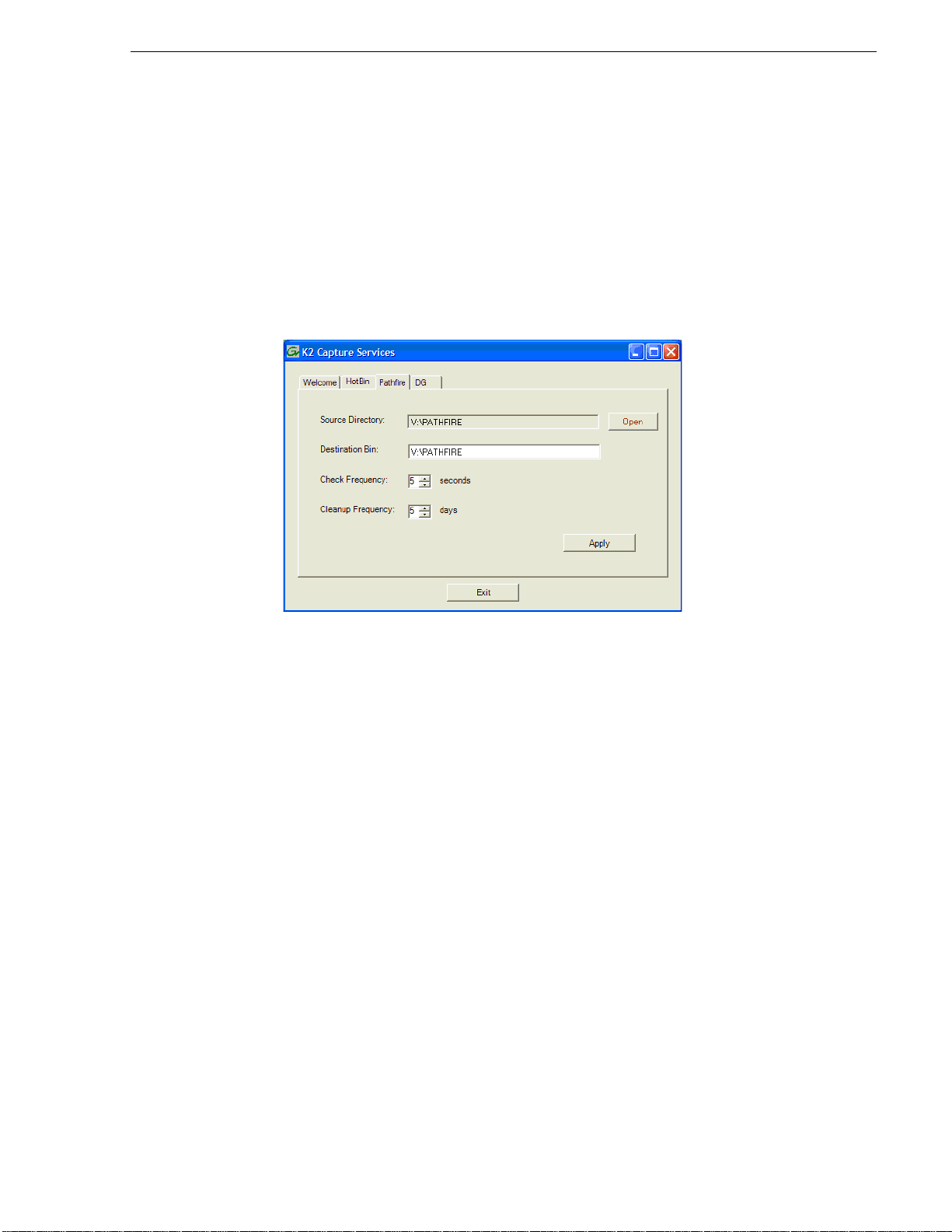
Configuring the Pathfire capture service
1. From the Start menu, access the Programs menu and select Grass Valley | K2
Capture Services
The K2 Capture Services utility dialog box is displayed.
2. Click on the Pathfire tab.
If you have not yet licensed the Pathfire capture service, a “…start the process of
getting a license now?” message appears. Follow on-screen instructions to obtain
a license. After licensing, restart the K2 Capture Services utility and continue with
this procedure.
.
3. Enter the paths to the source directory and destination bin, which are defined as
follows:
• Source Directory — This is the watch ed folder. It is a standard file system
directory. It must be on the K2 system’s V: drive. When a file is placed in this
directory, the Pathfire capture service automatically imports it into the K2 media
storage.
NOTE: The directory you configure here as the Source Directory must be
configured as a destination for Pathfire-delivered content.
• Destination Bin — The cli p bin in the K2 media stor age that re ceives th e media
imported by the K2 Pathfire capture service. The destination bin is in the K2
media database and i t app ears in AppCenter as a media bin. T he bin must be on
the K2 system’s V: drive. If y ou specify a destinati on bin name th at does no t yet
exist, the K2 system creates it when files are imported to it.
4. For Check Frequency, it is recommended that you accept the default value. This
value specifies how often you want the capture service to check the source
directory for new files.
5. For the Cleanup Frequency, it is recommended that you accept the default value.
This value specifies
the maximum age of files in the source directory. The
capture service deletes files that are older than this age.
6. When your Pathfire capture service settings are complete, click
Apply.
June 9, 2009 K2 Media Client System Guide 91
Page 92

Chapter 3 System connections and configuration
7. A success message displays. Click OK. The Pathfire capture service starts up and
continues to run after you exit.
The service immediately checks the source directory for any files that are beyond
the specified cleanup age and deletes them from the directory.
Testing the Pathfire capture service
1. In the Pathfire application, drag Pathfire-delivered content onto the K2 system.
2. On the K2 System, open Windows Explorer, browse to the watched folder and
verify that the fi les hav e arri ved from Pathf ire. The transf er fr om Path fire mus t be
100% complete before the K2 Pathfire capture service triggers the import into K2
media storage.
3. Open AppCen ter and use Transf er Monitor to verify that the transfer int o K2 media
storage is underway.
4. After the transfer into K2 media storage completes, verify that the media appears
in the destination bin.
5. Playout the media to verify that the import was successful.
Pathfire capture service components
The following table describes the components that support K2 Pathfire capture
service functionality.
Name Description
Grass Valley Pathfire Bin
service
K2 Capture Services utility Configures K2 capture services.
Source directory This is the watched folder. It is a standard file system directory. When
Check frequency Determines how often (in seconds) the wat ched folder is checked for
Cleanup frequency Determines how long (in days) a file remains in the watched folder. A
Destination bin The clip bin in the K2 media storage that receives the media imported
DMGtransfer.exe A program installed with Pathfire Transfer Service software. It
This is the Pathfire capture service. It is the service that does the
automatic import from the watched folder (source di rectory) to the K2
media storage (destination bin).
a file is placed in this directory, the Pathfire capture service
automatically imports it into the K2 media storage. By default, the
location of the source directory is
new files.
file with a file-creation date older than the specified nu mber of days is
deleted.
by the K2 Pathfire capture service. The destination bin is in the K2
media database and appears in AppCenter as a media bin. By default,
it location is V:\PATHFIRE.
appears only in the Windows operating system Task Man ager.
V:\PATHFIRE.
Pathfire EsdClient service A service installed with Pathfire Transfer Service software. It appears
in the Windows operating system Services control pa nel. Its status
should be Started, with startup type Automatic.
92 K2 Media Client System Guide June 9, 2009
Page 93

Name Description
Pathfire logs Find Pathfire logs at C:\Program Files\pathfire\logs.
Catch server A generic term for a server dedicated to the purpose of downloading,
capturing, and managing media content as i t arr ives via a specific
distribution mechanism at a broadcast or media production facility.
Examples of catch servers are a Pathfire DMG Server and a DG Spot
Box.
Pathfire capture service procedures
Use the following procedures as necessary to support the operation of the Pathfire
capture service in your facility.
Recovery after a failed Pathfire transfer
If the transfer of the Path fire-delivered content i nto the watch ed folder fails, the
Pathfire system mana ges the fa ilur e and re ports e rr ors. For some fa il ure modes , suc h
as a network outage , there might b e some *.tmp files remaining in the watched f older
as a result of the failed transfer. These files do not cause problems with subsequent
transfers. Once you cor rect the pr oblem tha t caus ed the ori ginal fail ure, i f you re start
the Pathfire transfer service and then transfer the same Pathfire-delivered content
again, the transfer is successful. If the content is not transferred again, the *.tmp files
persist until manually deleted.
Pathfire capture service procedures
Installing Pathfire Transfer Service software
To support K2 Capture Service features for automatically importing media from a
Pathfire catch server , Pat hfi re soft ware must be installed on a stan d-alone K2 Media
Client or on a K2 M edi a Ser ver . This software is Pathfire soft ware , not Grass Valley
software. Likewise, its license is a Pathfire licen se, not a Grass Valley lice nse.
You must procure a license file for t he Pathfir e license. Follow the in structions on the
Software License sheet th at you receiv ed from Grass Valley. You must prepare a text
file with unique system identifiers and send the text file to Grass Valley in order to
received license files.
Refer to K2 Release Notes for information on the compatible version of Pathfire
Transfer Service soft ware.
NOTE: The Pathfire Transfer Service software install deletes files in C:\temp. If
you have any files in C:\temp that you want to sa ve, copy the files to a d ifferent
location before proceeding.
To install Pathfire software, you must run multiple installation programs, as directed
by the following procedures:
Install first DMG Master software
1. If you have any files in C:\temp that you want to s ave , copy the files t o a di ff er ent
location.
2. Place the Pathfire Transfer Service CD in the CD-ROM drive of the K2 Media
Client or K2 Media Server.
June 9, 2009 K2 Media Client System Guide 93
Page 94

Chapter 3 System connections and configuration
3. On the CD, open DMGMASTER40IT79.exe. The name of this file might change
slightly, depending on the version of Pathfire Transfer Service software.
InstallShield Wizard opens and extracts files for two sets of data. The entire
extracting process is less than 3 minutes. When the process completes, the Pathfire
Digital Media Gateway Installation program opens and runs.
4. When the Welcome to the InstallShield Wiza rd for DMG wi ndow displa ys, click
Next to progress through the wizard.
5. When you arrive at the License Agreement window, click
6. In th e Install ation Type window, select
Next.
7. In t he Enter Text window, e nter the IP addres s of the Pathfire DMG Receive Server
from which you are pulling content as input for the K2 Pathfire capture service.
If an IP address is already entered, it is the IP address of the server as detected from
a previous install.
8. Once the IP address of the Pathf ire DMG Receive Server is co rrectly entere d, click
Next.
A series of message boxes display for approximately twelve minutes as the
necessary “skins” are ins talled. Once completed, the DMG Insta ll Complete dialog
box displays.
9. In the DMG Install Complete dialog box, respond as appropriate to restart and
allow the K2 Media Client o r K2 Media Server to resta rt.
10.Continue with the next procedure “Install second DMG Master software”.
Install second DMG Master software
Prerequisites for this procedure are as follows:
• The first DMG Master software is installed on the K2 Media Client or K2 Media
Server.
Yes.
Station Integration (3xx , 6xx) and then c lick
1. If you have any files in C:\temp that you want to save and you have not already
done so, copy the files to a different location.
2. If you have not already done so, place the Transfer Service CD in the CD-ROM
drive of the K2 Media Client or K2 Media Server.
3. On the CD, open DMGMASTER.exe.
InstallShield Wizard opens and extracts files.
The Pathfire Digital Media Gateway Installation program opens and runs
installation processes. This takes approximately two minutes. When installation
processes are complete, the DMG Install Complete dialog box displays.
4. In the DMG Install Complete dialog box, respond as appropriate to restart and
allow the K2 Media Client o r K2 Media Server to resta rt..
5. Continue with the next procedure “Install DMG Transfer Se rvice softwa re”.
94 K2 Media Client System Guide June 9, 2009
Page 95

Install DMG Transfer Service software
Prerequisites for this procedure are as follows:
• The first DMG Master soft ware and the second DM G Master so ftware is install ed
on the K2 Media Client or K2 Media Server.
Transfer Service has the capability to transfer HD content and SD content. However,
HD does not transfer to a SD destination nor does SD transfer to a HD destination.
Therefore, if both types of content flow through the Transfer Service process, they
each require their own destination.
1. If you have any files in C:\temp that you want to save and you have not already
done so, copy the files to a different location.
2. If you have not already done so, place the Transfer Service CD in the CD-ROM
drive of the K2 Media Client or K2 Media Server.
3. On the CD, open DMGTRANSFER.exe.
InstallShield Wizard opens and extracts files, then the Pathfire Digital Media
Gateway Installation program opens.
Installing Pathfire Transfer Service software
4. In the Information window, click
5. In the Type window, select
6. In the Destinations window, select
Next.
Server Connect for Programming and then click Next.
Configure destination one and then click Next.
If SD and HD destinations are required, configure the SD first.
7. In the Enter Text window, type the name of the K2 Media Client or K2 Media
Server on which you are now installing the P athfire soft ware.
This name does not have to match any DNS names or comput er names. Howev er,
it should be a name that is recognized when working in the Destinations window
of the Pathfire DMG appl ication.
8. In the Destinations window, click
Next.
9. In the next Enter Text window, type a description that applies to the K2 Media
Client or K2 Media Server on which you are now i nstalling the Pathfire sof twar e,
and then click
10.In the Transfer Engine window, select
Next.
DirectConnect and then click Next.
11.In the Video Resol ution window, s elect the vi deo resolutio n for this d estination . If
SD and HD destinations are required, configure destination one for SD and
destination two for HD. Then click
Next.
The Enter default output directory window dialog box opens.
12.Enter the path that specifies the K2 Pathfire capture service watched folder and
then click
OK.
In the K2 Capture Services utility, this watched folder is labeled the Source
Directory.
13.In the Destinations window, do one of the following:
• If you require anothe r destinatio n (such as the HD desti nation), sele ct
destination two
June 9, 2009 K2 Media Client System Guide 95
and click Next. Repeat previous steps to configure the
Configure
Page 96

Chapter 3 System connections and configuration
destination.
• If all your required destina tions are confi gured, sele ct
After a few seconds of inactivity, a series of install windows flash.
When the install is complete the installation programs close and the Windows
desktop appears.
14.Restart (boot) the K2 Media Client or K2 Media Server using the Windows
operating system restart procedure.
15.Continue with the next procedure “Licensin g Pat h f ir e Tr ans fer Service soft ware ” .
Licensing Pathfire Transfer Service software
There are two licenses re quired for operation of the Pathfire capture serv ice, as
follows:
• The Pathfire Transfe r Se rvi ce license, as expl ai ned in this section. The l ice nse for
Pathfire Transf er Servi ce soft ware is a Path fire l icense, n ot a Grass Vall ey lice nse.
You must license the Pathfire software on the stand-alone K2 Media Client or the
K2 Media Server.
• The K2 Pathfire capture service license, which is a Grass Valley license. Refer to
“Licensing K2 capture service software” on page 104.
Prerequisites for this procedure are as follows:
• The first DMG Master softwar e, the se cond DMG Mast er softwar e, and t he DMG
Transfer Service is installed on the K2 Media Client or K2 Media Server.
Done and then click Next.
• You have procured the license file. Follow the instruct ions on the Software License
sheet that you r eceived from Gras s Valley. You must prep are a text file with unique
system identifi ers and send the tex t file t o Grass Valle y in order to receive d license
files.
1. Copy the license file to C:\Program Files\pathfire\dmg\skippy\dat.
2. Click
3. Press
4. Click
5. In Task Manager, confirm that
Start | All Programs | StartUp | Transfer.
Ctrl + Alt + Delete. The Windows Security dialog box opens.
Task Manager. Windows Task Manager opens.
DMGTransfer.exe is running.
6. Restart (boot) the K2 Media Client or K2 Media Server using the Windows
operating system restart procedure.
The Pathfire software is installed and licensed.
96 K2 Media Client System Guide June 9, 2009
Page 97

Using the DG capture service
The following sections provide information for the K2 DG capture service.
• “About the DG capture service”
• “Prerequisites for using the DG capture service”
• “Configuring the DG capture service”
• “Testing the DG capture service”
• “DG capture service procedures”
• “DG capture servic e components”
About the DG capture service
The K2 DG capture service provi des a way to have DG spots automat ically impo rted
into a K2 system. The DG capture service watches for DG spots as they become
available on DG Spot Box. When an op erator on the DB Spot Box assigns a house ID
to a DG spot, the spot is detected by the K2 DG capture service. The capture service
then goes into act ion and does th e necessar y processing to import the spot into the K2
media storage. This is similar to what happens when you manually import media
using K2 AppCenter import features. The spot i s then available a s a K2 clip, ready fo r
playout.
Using the DG capture service
The K2 DG capture service controls transfers and manages house IDs for spots. In
order to track house IDs, the K2 capt ure service cr eates two insta nces in the K2 medi a
database for eac h spot. One i nstanc e is i n the desti natio n bin. The other inst ance i s in
a tracking bin. Playout and other normal media operations take place from the
destination bin. The tracking bin is used internally by the DG capture service for
house ID tracking purposes. The tracking bin is not available for normal operations.
The DG capture service mus t r un on a K2 system that host s t he K2 FTP interface, as
follows:
• A stand-alone K2 Media Client — The K2 DG capture service imports DG spots
into the internal media storage or direct-connect media storage of the K2 Media
Client.
• A K2 Media Server with role of FTP s erver — The K2 DG capture servi ce imports
DG spots into the shared media storage of the K2 SAN.
Prerequisites for using the DG capture service
Before you can configure an d use the DG capture servi ce, the following req uirements
must be satisfied:
• K2 system software must be at a version that supports the DG capture service.
Refer to K2 Release Notes for information on DG capture service support.
• The DG capture service must be licensed on the stand-alone K2 Media Client or
K2 Media Serv er. This is a Grass Valley software license.
• The DG system in your facil ity must be installed and op erating correctly befor e you
can integrate it with the K2 DG capture service.
June 9, 2009 K2 Media Client System Guide 97
Page 98

Chapter 3 System connections and configuration
Use procedures later in this section as appropriate to satisfy pre-requisites.
Configuring the DG capture service
When configuring the K2 DG capture service, bear in mind the following
considerations:
• You must be logged in with a dminist rato r priv ilege s on the s tand- alon e K2 Media
Client or the K2 Media Server.
• If using the DG capture service on a K2 SAN, the K2 Capture Services utility must
be on a K2 Media Server that is also an FTP server. If your K2 SAN has multiple
FTP servers, the utility must be on the primary FTP server.
• Imports are serializ ed. For example, i f two clips become ava ilable on t he DG Spot
Box, the DG capture service does not queue the second clip for import until the first
clip is finished importing. This is different th an the ordinary K2 trans f er process.
• DG capture service import s are seri aliz ed with oth er K2 tr ansfer s. For exampl e, if
fourteen items are already queued up from ordinary K2 transfers, and a DG spot
becomes available for import, the import triggered by the DG capture service
becomes the fifteenth clip in the transfer queue.
To configure the DG capture service, follow these steps:
1. From the
Capture Services
Start menu, access the Programs menu and select Grass Valley | K2
.
The K2 Capture Services utility dialog box is displayed.
2. Click on the DG tab.
If you have not yet licensed the DG capture service, a “…start the process of
getting a license now?” message appears. Follow on-screen instructions to obtain
a license. Afte r licen sing, re start the K2 Capture Se rvices u tility and c ontinue with
this procedure.
3. Enter the paths to the destination bin and the tracking bin, which are defined as
follows:
98 K2 Media Client System Guide June 9, 2009
Page 99

Testing the DG capture service
• Destination Bin — This is the clip bin in the K2 media storage that receives the
media imported by the DG captu re service. The des tination bin is defi ned by the
K2 media database and appears in AppCenter as a media bin. The bin must be
on the K2 system’s V: drive.
• Tracking Bin — This is another clip bin in the K2 media storage. This bin is used
by the K2 capture service. It stores a second instance of each spot, for the
purpose of tracking house IDs. You do not use it for normal K2 media
operations. The bin must be on the K2 system’s V: drive. If you specify a bin
name that does not yet ex ist, the K2 system c reates it wh en files are import ed to
it.
4. Set t he Capacity, which specif ies the maximum number of DG spot s retained in K2
media storage. When this maximum number is reached, the DG capture service
deletes the fi ve oldest spots f rom the K2 media s torage. Set the ca pacity to be lar ger
than the capacity of the DG Spot Box.
5. Click
Add. The New Server Information dialog box opens.
6. Enter the IP address of the DG Spot Box and click
7. When your DG capt ure service settings are compl et e, on t he K2 Capture Services
utility dialog box, click
Apply.
8. A success message displays. Click
continues to run after you exit.
Testing the DG capture service
1. On the DG Spot Box, assign a house ID to a spot.
OK.
OK. The DG capture service starts up and
2. On the K2 system, open AppCenter and verify that the media has been imported
into the destination bin.
3. Playout the media to verify that the import was successful.
DG capture service procedures
Use the following pro cedures as ne cessary to support the o peration of the DG capture
service in your facility.
June 9, 2009 K2 Media Client System Guide 99
Page 100

Chapter 3 System connections and configuration
Deleting a spot
If you want to dele te a s pot, y ou mu st de lete for a ll in stan ces of the s pot i n th e pro per
sequence so that no references to the house ID remain. Use the following procedure:
1. In AppCenter, delete the spot from the destination bin.
2. In AppCenter, delete the spot from the tracking bin.
3. On the DG Spot Box, delete the spot.
DG capture service components
The following table describes the components that support K2 DG capture service
functionality.
Name Description
Grass Valley DG Capture
service
K2 Capture Services utility Configures K2 capture services.
Destination Bin Thi s is the clip bin in the K2 media storage that receives the media
This is the DG capture service. It is the service that does the automatic
import of DG spots to the K2 media storage.
imported by the DG capture service. The destination bin is in the K2
media database and appears in AppCenter as a media bin. The bin must
be on the K2 system’s V: drive. By default, the location is
V:\DG.
Shallow Copy Bin This is another clip bin in the K2 media storage. This bin is used by the
K2 capture service. It stores a second instance of each spot, for the
purpose of track ing hous e IDs. Y ou do n ot use it f or norm al K2 me dia
operations. The bin must be on the K2 system’s V: drive. By default,
the location is
Capacity The maximum number of DG spots retained in K2 medi a storage.
When this maximum number is reach ed, the DG capture service
deletes the five oldest spots from the K2 media storage.
Catch server A generic term for a server dedicated to the purpose of downloading,
capturing, and managing media content as it arrives via a specific
distribution mechanism at a broadcast or media production facility.
Examples of catch servers are a Pathfire DMG Server and a DG Spot
Box.
V:\DG_Tracking.
100 K2 Media Client System Guide June 9, 2009
 Loading...