

Page 1
K2
MEDIA CLIENT
Service Manual
071-8468-06
JULY 2008
Page 2

Copyright Copyright © 2008 Grass Valley, Inc. All rights reserved. Printed in the United States of America.
Portions of software © 2000 – 2008, Microsoft Corporation. All rights reserved. This document
may not be copied in whole or in part, or otherwise reproduced except as specifically permitted
under U.S. copyright law, without the prior written consent of Grass Valley, Inc., P.O. Box
59900, Nevada City, California 95959-7900. This product may be covered by one or more U.S.
and foreign patents.
Disclaimer Product options and specifications subject to change without notice. The information in this
manual is furnished for informational use only, is subject to change without notice, and should
not be construed as a commitment by Grass Valley, Inc. Grass Valley, Inc. assumes no
responsibility or liability for any errors or inacc uracies that may appear in this publication.
U.S. Government
Restricted Rights
Legend
Trademarks and
Logos
Revision Status
Use, duplication, or disclosure by the United States Government is subject to restrictions as set
forth in subparagraph (c)(1)(ii) of the Rights in Technical Data and Computer Software clause
at DFARS 252.277-7013 or in subparagraph c(1) and (2) of the Commercial Computer
Software Restricted Rights clause at FAR 52.227-19, as applicable. Manufacturer is Grass
Valley, Inc., P.O. Box 59900, Nevada City, California 95959-7900 U.S.A.
Grass Valley, K2, Aurora, Infinity, Turbo, M-Series, Profile, Profile XP, NetCentral,
NewsBrowse, NewsEdit, NewsQ, NewsShare, Ne wsQ Pro, and Media Manager are either
registered trademarks or trademarks of Grass Valley, Inc. in the United States and/or other
countries. Grass Valley, Inc. products are covered by U.S. and foreign patents, issued and
pending. Additional information regarding Grass Valley, Inc. trademarks and other proprietary
rights may be found at www.thomsongrassvalley.com.
Other trademarks and logos used in this document are either registered trademarks or
trademarks of the manufacturers or vendors of the associated products, such as Microsoft®
Windows® operating system, Windows Media® play er, Internet Explorer® internet browser,
and SQL Server™. QuickTime and the QuickTime logo are trademarks or registered
trademarks of Apple Computer, Inc., used under license therefrom.
Rev Date Description
November 23,
2005
Initial release of the K2 Media Client Service Manual— 071-8468-00
September 6,
2006
July 3, 2007 Added information for new K2 Media Client models — 071-8468-02
September 7,
2007
January 11, 2008 Revised information for Type II motherboard — 071-8468-04
March 28, 2008 Revised information for Type III motherboard — 071-8468-05
July 28, 2008 Updates to information for services, FC card, motherboard, SCSI
Changes to recovery and networking procedures — 071-8468-01
Revised information for direct-connect storage, teaming —
071-8468-03
interface board — 071-8468-06
2 K2 Media Client Service Manual July 28, 2008
Page 3

Contents
Safety Summaries..............................................................................................7
Finding Information...........................................................................................13
Grass Valley Product Support.................................................................................16
Chapter 1 Product Description
Overview description...............................................................................................20
K2 Media Client orientation.....................................................................................20
Front view components............................................ ...... ................................. ...20
Rear view components SDA-00 model...............................................................21
Rear view components SD-00 model.................................................................22
Rear view components HD-00 model.................................................................23
FRU functional descriptions ....................................................................................24
Base chassis ................................................. ..... ...... .................................. ..... ...24
Fan module.........................................................................................................24
RAID drives ........................................................................................................24
Power supplies...................................................................................................25
Removable media drives.......................................... ...... ..... ...............................25
Codec board.......................................................................................................25
Mezzanine boards..............................................................................................26
RTP board.......................................... ..... ...... ..... ...... .................................. ..... ...26
XLR board ..........................................................................................................26
RS-422 adapters ................................................................................................26
Dual Ethernet adapter ........................................................................................26
Graphics board...................................................................................................27
SCSI controller adapter................................. ................................. ...... ...... ..... ...27
SCSI interface board..................................... ..... .................................. ...... ..... ...27
SCSI backplane.................................. ..... ...... ..... ...... ...... ................................. ...27
CPU motherboard...............................................................................................27
Status indicators......................................................................................................28
Front panel indicators............................................... ...... ..... ...... ..... ....................28
Rear panel indicators..........................................................................................29
System beep codes............................................ ...... ...... ..... ...............................31
Chapter 2 System Messages
About system messages................... ...... ..... .................................. ..... ....................34
BIOS POST messages............................................................................................34
Critical system startup messag es........................................................ ...... ..............38
Viewing AppCenter system status messages.........................................................38
Viewing system status messages.......................................................................39
Copying StatusPane messages to the clip board...............................................40
Clearing messages.............................................................. ...... ..... ....................40
Chapter 3 Service Procedures
Exporting log files....................................................................................................41
Replacing a RAID 0 drive........................................................................................43
Replacing a RAID 1 drive........................................................................................43
Restoring network configuration..............................................................................44
Install the loop-back adapter ..............................................................................45
Identify adapters.................................................................................................45
Set Rx/Tx Descriptors Value ..............................................................................48
Create the Control Team..................................................... ...... ..... ...... ...... ..... ...49
Name team............................................................... .................................. ..... ...55
Reorder adapters................................................................................................56
Configuring Event Viewer........................................................................................57
Checking services...................................................................................................58
Services on a stand-alone storage K2 Media Client...........................................59
July 28, 2008 K2 Media Client Service Manual 3
Page 4

Contents
Services on an shared storage K2 Media Client................................................60
Checking pre-installed software..............................................................................61
K2 Media Client pre-installed software............................................................... 61
Grass Valley Control Point PC pre-installed software........................................ 62
Configuring NVRAM................................................................................................ 62
Making motherboard CMOS settings......................................................................65
Type I motherboard CMOS settings................................................................... 65
Type II motherboard CMOS settings..................................................................65
Type III motherboard CMOS settings ................................................................. 66
Rescanning PCI slots.............................................................................................. 67
Using recovery disk images.................................................................................... 67
About the recovery disk image process ............................................................. 67
Creating a recovery disk image for storing on E:............................................... 69
Creating a recovery disk image CD set..............................................................71
Restoring from a system-specific recovery disk image on E:............................. 72
Restoring from the generic recovery disk image on E:.......................................73
Restoring from a recovery disk image CD set....................................................76
Activating the Windows operating system.......................................................... 78
Installing the Fibre Channel card driver ..................................................................78
Replacing a K2 Media Client...................................................................................80
Chapter 4 Troubleshooting problems
Step 1: Check configurations.................................................................................. 82
Step 2: Check connections and external equipment............................................... 82
Step 3: Check system status messages................................................................. 82
Step 4: Identify problems using the startup sequence............................................ 82
Motherboard BIOS startup information ................................................................... 85
SCSI controller adapter BIOS startup information .................................................. 86
Motherboard BIOS startup summary screen...........................................................87
Shutdown/restart problems.....................................................................................87
Checking external equipment.................................................................................. 88
VGA display problems........................................................................................88
Keyboard problems............................................................................................ 88
Mouse problems............................................................ ...... ..... ...... ..... ...... ......... 88
Power connection sequence................................................................................... 89
Motherboard/BIOS startup...................................................................................... 89
Windows startup............................... ...... ...... ................................. ..........................89
K2 Media Client system startup ..............................................................................90
Thermal problems...................................................................................................91
Codec board problems............................................................................................91
Power supply problems...........................................................................................91
CD drive problems .................................................................................................. 92
Video problems.......................................................................................................93
Audio problems.......................................................................................................94
Timecode problems.......................... ...... .................................. ...............................95
Operational problems..............................................................................................96
System problems .............................................. ...... ................................. ...... ......... 97
Storage problems.................................................................................................... 98
Media File System problems..............................................................................98
Media disk problems .......................................................................................... 98
Checking the storage system.............................................................................100
Network, transfer, and streaming problems............................................................ 101
Chapter 5 Removing and replacing FRUs
External Parts Removal ........................................................... ..... ...... .................... 104
Opening the front bezel......................................................................................104
Fan module removal...........................................................................................105
4 K2 Media Client Service Manual July 28, 2008
Page 5

Front panel removal................................. .................................. ..... ....................106
RAID disk removal..............................................................................................107
Power supply removal........................................................................................107
Internal Parts Removal............................................................. ...... ..... ...... ...... ........108
Top cover removal..............................................................................................109
SCSI interface board removal ............................................................................110
Removable media drive removal........................................................................111
Codec board removal.........................................................................................112
Mezzanine board removal..................................................................................114
RTP board removal ............................................................. ...... .........................115
Rear card guide removal............................... ................................. ....................116
SCSI backplane removal.......................................... ...... ................................. ...117
RS-422 adapter removal ....................................................................................119
Graphics board removal.....................................................................................121
Dual Ethernet adapter removal...........................................................................122
SCSI controller adapter removal ........................................................................123
XLR board removal.............................................................................................124
Center support bracket removal........................................................... ...... ..... ...125
CPU motherboard replacement..........................................................................126
Index......................................................................................................................139
July 28, 2008 K2 Media Client Service Manual 5
Page 6

Contents
6 K2 Media Client Service Manual July 28, 2008
Page 7

Safety Summaries
General Safety Summary
Review the following saf ety precautions to avoid inj ury and prevent damage
to this product or any products connected to it.
Only qualified personnel should perform service procedures.
While using this pr oduct, you may need to ac cess oth er part s of t he sy stem .
Read the General Safety summary in other system manuals for warnings and
cautions related to operating the system.
Injury Precautions
Use Proper Power Cord
To avoid fire hazard, use only the power cord specified for this product.
Ground the Product
This product is grounded through the grounding conductor of the power
cord. To avoid electric shock, the grounding conductor must be connected
to earth ground. Before maki ng connections to t he input or outpu t terminals
of the product, ensure that the product is properly grounded.
Do Not Operate Without Covers
To avoid electric shock or fire hazard, do not operate this product with
covers or panels removed.
Do Not operate in Wet/Damp Conditions
To avoid electric shock, do not operate this product in wet or damp
conditions.
Do Not Operate in an Explosive Atmosphere
To avoid injury or fire hazard, do not operate this product in an explosive
atmosphere.
Avoid Exposed Circuitry
To avoid injury, remove jewelr y such as rings, watches, and other meta ll ic
objects. Do not touch ex posed conn ectio ns and components when power is
present.
Product Damage Precautions
Use Proper Power Source
Do not operate this product f rom a power sour ce that applie s more than the
voltage specified.
Provide Proper Ventilation
To prevent product overheating, provide proper ventilation.
July 28, 2008 K2 Media Client Service Manual 7
Page 8

Safety Summaries
!
!
!
Do Not Operate With Suspected Failures
If you suspect there is da mage to this product, have it in spected by q ualifie d
service personnel.
Battery Replacement
To avoid damage, replace only wit h the same or equivalen t type. Dispose of
used battery according to the circuit board m anufacturer’s instructions.
Safety Terms and Symbols
Terms in This Manual
These terms may appear in this manual:
WARNING: Warning statements identify conditions or practices that can
result in personal injury or loss of life.
CAUTION: Caution statements identify conditions or practices that may
result in damage to equipment or other property, or which may cause
equipment crucial to your business environment to become temporarily
non-operational.
Terms on the Product
These terms may appear on the product:
DANGER indicates a personal inj ury hazard immedi ately access ible as one
reads the ma rking.
WARNING indicates a personal injury hazard not immediately accessible
as you read the marking.
CAUTION indicates a hazard to property including the product.
Symbols on the Product
The following symbols may appear on the product:
DANGER high voltage
Protective ground (earth) terminal
ATTENTION – refer to manual
8 K2 Media Client Service Manual July 28, 2008
Page 9

Service Safety Summary
!
WARNING: The service instructions in this manual are intended for
use by qualified service personnel only. To avoid personal injury, do
not perform any servicing unless you are qualified t o do so. Refer to al l
safety summaries before performing service.
Do Not Service Alone
Do not perform interna l service or adj ustment of this product unless ano ther
person capable of rendering first aid and resuscitation is present.
Disconnect Power
To avoid electric shock, discon nect the main power by means of the power
cord or, if provided, the power switch.
Use Care When Servicing With Power On
Dangerous voltages or cur rents may exist in t his product. Disconnec t power
and remove battery (if applicable) before removing protective panels,
soldering, or replacing components.
To avoid electric shock, do not touch exposed connections
Certifications and Compliances
Canadian Certified Power Cords
Canadian approval includes the products and power cords appropriate for
use in the North America power network. All other power cords supplied are
approved for the country of use.
FCC Emission Control
This equipment has been tested and found to comply with the limits for a
Class A digital device, pursuant to Part 15 of the FCC Rules. These limits
are designed to provide reasonable protection against harmful interference
when the equipment is operated in a commercial environment. This
equipment generates, uses, and can radiate radio frequency energy and, if
not installed and use d in accordance with th e instructio n manual, may cause
harmful interfere nce to radio communication s. Operation of thi s equipment
in a residential area is likely to cause harmful interference in which case the
user will be required to cor rect the interference at his own expense. Changes
or modifications not expressly approved by Grass Valley can affect
emission compliance and could void the user’s authority to operate this
equipment.
July 28, 2008 K2 Media Client Service Manual 9
Page 10

Safety Summaries
Canadian EMC Notice of Compliance
EN55103 1/2
Class A Warning
FCC Emission Limits
This digital apparatus does not exceed the Class A limits for radio noise
emissions from digital apparatus set out in the Radio Interference
Regulations of the Canadian Department of Communications.
Le présent appareil numérique n’émet pas de bruits radioélectriques
dépassant les limites applicables aux appareils numériques de la classe A
préscrites dans le Règlement sur le brouillage radioélectrique édicté par le
ministère des Communications du Canada.
This product has been evaluated for Electromagnetic Compatibility under
the EN 55103-1/2 standards for Emissions and Immunity and meets the
requiremen ts for E4 environment.
This product complies with Class A (E4 environment). In a domestic
environment this product may cause radio interference in which case the
user may be required to take adequate measures.
This device complies with Part 15 of the FCC Rules. Operation is subject to
the following two conditions: (1) This device may not cause harmful
interference, and (2) this device must accep t any interf erence rece ived,
including interference that may cause undesirable operation.
Laser Compliance
Laser Safety Requirements
The device used in thi s product is a Class 1 cert ified laser product. Op erating
this product outsi de specifications or al te ring its original des ign ma y re sult
in hazardous radiati on exposure, and may be consi dered an act of modifying
or new manufacturing o f a laser product under U.S. regula tions contained i n
21CFR Chapter 1, subchapter J or CENELEC regulations in HD 482 S1.
People performing such an act are re quired by law to recertify and re identify
this product in accordance with provisions of 21CFR subchapter J for
distribution within th e U. S.A., and in ac cor danc e wit h CENELEC HD 482
S1 for distribution within countries using the IEC 825 standard.
Laser Safety
Laser safety in the United States is regulated by the Center for Devices and
Radiological Health ( CDRH). The la ser sa fety regulations are publ is hed i n
the “Laser Product Performance Standard,” Code of Federal Regulation
(CFR), Title 21, Subchapter J.
The International Electrotechnical Commission (IEC) Standard 825,
“Radiation of Laser Produ cts, Equipmen t Classific ation, Requi rements and
User’s Guide,” govern s laser products outside the United States. Europe an d
member nations of the European Free Trade Association fall under the
jurisdiction of the Comité Européen de Normalization Electrotechnique
(CENELEC).
10 K2 Media Client Service Manual July 28, 2008
Page 11

Safety Certification
This product has been evaluated and meets the following Safety
Certificat i on Standard s:
Standard Designed/tested for compliance with:
ANSI/UL60950, CAN/CSA
C22.2 No. 60950-00
12/01/2000
IEC 950 Safety of Information Technology Equipment, including
EN60950 Safety of Information Technology Equipment, including
Safety of Information Techno logy Equi pment, inclu ding
Electrical Business Equipment (Third edit ion).
Electrical Business Equipment (Third edition, 1999).
Electrical Business Equipment (Third Ed iti on 2000).
July 28, 2008 K2 Media Client Service Manual 11
Page 12

Safety Summaries
12 K2 Media Client Service Manual July 28, 2008
Page 13

Finding Information
This service manual provides procedures for serv icing the K2 Media Client to the
field-replaceabl e unit level. Use thi s manual to isolate pr oblems to a board or module,
such as the Power Supply, and to make repairs through module exchange.
How this manual is org anized
This manual is organized around the tasks required to service the K2 Media Client.
The following describes the chapters included in this manual:
Chapter 1, Product Description — Describes the key features, system components,
and status indicators of the K2 Media Client.
Chapter 2, System Messages — List s the variou s messages a nd system codes that you
might encounter as you use the K2 Media Client.
Chapter 3, Service Proc edures — Conta ins pr ocedure s for period ic main te nance an d
repair.
Chapter 4, Troubleshoot ing problems — Contains problem de scriptions with steps for
diagnosing and correcting the cause of the problem. Use this information if you are
having trouble with your K2 Media Client.
Chapter 5, Removing and repla ci ng FRUs — Contains procedur es f or r emovi ng a nd
replacing field replaceable hardware components.
July 28, 2008 K2 Media Client Service Manual 13
Page 14
Finding Information
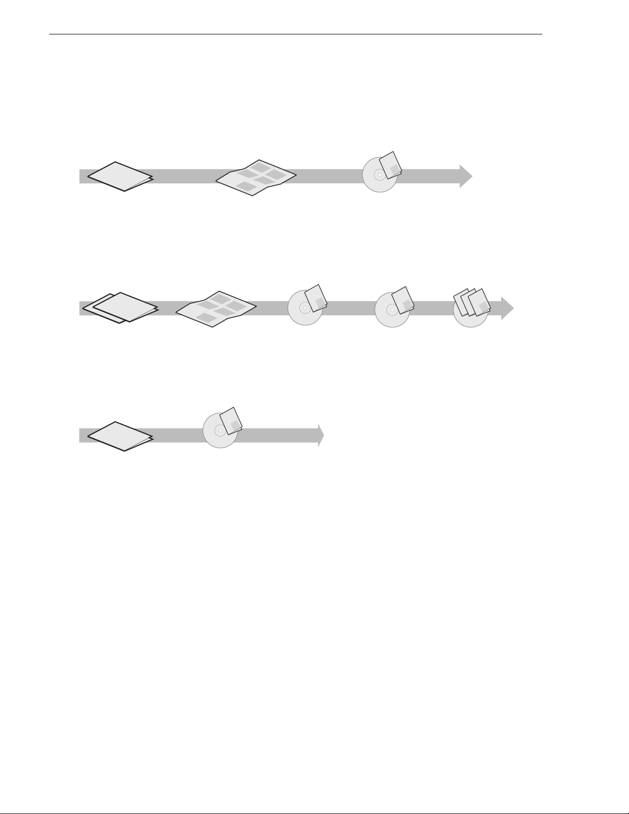
Getting more information
The following illustration shows the recommended order in which to reference the
documentation.
Path for the installer of K2 Media Client models with stand-alone storage
r
Se
es
s
i
P
r
e
Ser
X
i
P
s
Se
f
X
o
ie
Valley Group
s
f
XP
e
Ser
y
i
P
s
o
Ser
l
f
e
y
i
X
s
i
P
o
f
e
Ser
il
X
y
i
Grass
P
m
Fam
o
a
f
il
y
X
F
o
f
am
il
o
y
F
m
l
a
y
i
F
l
i
am
m
F
Fa
K2 Media Client
Release Notes
The latest information about the
hardware and software shipped
with the system. Packaged with
K2 Media Client.
t
r
ta
nt
S
k
ume
c
Qui
is doc
you
K2
Th
ps
you
el
h
ps
you
el
h
ps
el
h
Quick Start Guide
The essential steps for installing
the K2 Media Client. Different
models each have their own
version, packaged with the K2
Media Client.
Grass Valley
K2 Manual
Documentation
CD
K2 Media Client
System Guide*
Specifications and
instructions for
system settings.
Path for the installer of the K2 Storage System with connected K2 Media Clients
ley
Val
Grass
K2 Manual
s
S
e
s
S
e
ri
XP
i
e
s
s
lley Group
r
S
S
e
e
XP
f
e
s
s
S
o
e
ri
ri
S
e
f
XP
XP
i
e
e
s
i
o
y
s
r
S
e
r
S
XP
l
e
f
f
e
XP
i
y
e
s
s
i
i
o
o
r
S
S
l
Valley Group
e
e
f
m
r
XP
f
e
i
XP
o
a
y
e
y
s
o
Grass Va
m
ri
ri
S
F
l
l
e
f
XP
XP
a
f
e
e
y
s
i
i
i
o
y
S
F
o
l
e
m
r
l
f
f
i
XP
am
y
e
i
o
o
Grass
y
m
ri
Fa
F
l
m
XP
l
a
f
e
i
a
y
y
i
F
o
m
F
l
l
f
i
i
o
am
y
Fa
m
m
F
l
a
a
y
F
F
l
mi
i
m
Fa
a
F
rt
t
a
t
n
e
S
k
c
Qui
u
docum
is
u
K2
Th
ps yo
yo
u
hel
ps
hel
ps yo
hel
Documentation
CD
ley
Grass Val
K2 Manual
Documentation
CD
K2 Media Client and
K2 Storage System**
Release Notes
The latest information
about the hardware and
software shipped with
the system.
Path for the operator
s
S
e
s
S
e
ri
XP
e
s
ri
S
e
XP
f
e
s
o
Valley Group
ri
S
e
f
XP
e
o
y
s
ri
S
l
e
f
XP
e
y
s
i
o
S
l
e
ri
f
i
XP
am
e
y
o
Grass
ri
F
l
XP
am
f
e
i
y
F
o
l
f
am
i
o
y
F
l
am
y
i
F
l
i
am
F
am
F
K2 Media Client
Release Notes
The latest information
about the hardware and
software shipped with
the system.
K2 Storage System
Cabling Guide**
Diagrams for
cabling K2 Storage
System devices.
Grass Valley
K2 Manual
Documentation
CD
K2 Media Client
User Manual*
Information for using the user
interface to record, play and
manage clips and to configure
channels.
K2 Storage System
Instruction Manual*
Instructions to
install/configure K2
Storage (SAN), with
K2 Media Client, K2
Media Server.
Find the K2 Documentation CD packaged with K2 Media
*
Clients and with K2 RAID Storage devices, primary chassis.
Find the Storage Release Notes and Cabling Guide
**
packaged with K2 RAID Storage devices, primary chassis.
K2 Media Client
System Guide*
Specifications and
instructions for
system settings.
Other Manuals*
Including:
Quick Start Guide
-
-
User Manual
- Service Manual
- RAID manuals
Quick Start Guide
You receive this guide in the product packaging with your K2 Media Client. The
Quick Start Guide provides step-by-step installation instructions for basic installation
and operation of your K2 Media Client, including recording and playing clips.
ley
Grass Val
Grass Valley
Grass Valley
K2 Manual
K2 Manual
K2 Manual
Documentation
CD
Release Notes
The release notes contain the latest information about the K2 Media Client software
shipped on your system. There are K2 Storage System release notes and K2 Media
Client release notes. The information in this document includes software upgrade
instructions, software specifications and requirements, feature changes from the
previous releases, and any known problems. Because rele ase notes contain the late st
information, they are printed out rather than included in the Documentation
CD-ROM.
14 K2 Media Client Service Manual July 28, 2008
Page 15

K2 Documentation CD
Except for the release notes, the full set of support documentation, including this
manual, is availabl e on the Documentati on CD-ROM that you rece ived with your K2
Media Client.
The K2 Documentation CD includes the following documents:
•
K2 Storage System Instruction Manual — Contains installation, configuration, and
maintenance procedures for shared storage options.
•
K2 Storage System Cabling Guide — Contains diagrams for cabling th e devi ce s of
the K2 Storage System.
•
RAID Instruction Manuals — There is an Instruc tion Manual for each typ e of RAI D
storage device that can be a part of a K2 Media Client. These manuals contain
procedures for configuring and servicing the device.
•
K2 Media Client System Guide — Contains the product specifications and
step-by-step instructions for modifying system settings. Includ es instruc tions for
adding a K2 Media Client to the K2 Storage System.
•
K2 Media Client Quick Start Guides — The Quick Start Gui des provides step-by-ste p
installation inst ructions for basic installation and oper ation of the K2 Media Clien t,
including recording and playing clips.
•
K2 Media Client User Manual — Describes the K2 Media Client and provides
instructions for configuring and operating the product.
•
K2 Media Client Service Manual — Contains information on servicing and
maintenance.
NetCentral documentation
The NetCentral product has its own documentation set, described as follows:
•
NetCentral User Guide — This is a printed manual. It provides instructions for
installing, using, and administering the NetCentral monitoring system.
•
NetCentral Help — From the N etCentral interface access on-line help as follow s:
• For general help with NetCe ntral manag er, sel ect
This content is identical to that in the NetCentral User Guide.
• For help specific to monitoring K2 Media Client system devices, select
Device Providers
and then select the monitored device.
Thomson Grass Valley Web Site
This public Web site contains all the latest manuals and documentation, and
additional support information. Use the following URL.
http://www.thomsongrassvalley.com.
Help | NetCentral Help Topics.
Help |
July 28, 2008 K2 Media Client Service Manual 15
Page 16

Finding Information
Grass Valley Product Support
T o get technica l assistance, che ck on the status of a ques tion, or to report new issue, contact
Grass Valley Product Support via e-mail, the Web, or by phone or fax.
Web Technical Support
To access support infor mation on the Web, v isit the pr oduct support Web page on the
Grass Valley Web site. Yo u ca n do wn loa d s oft war e or f ind sol utions to problems by
searching our Frequently Asked Questions (FAQ) database.
World Wide Web: http://www.thomsongrassvalley.com/support/
Technical Support E-mail Address: gvgtechsupport@thomson.net.
Phone Support
Use the following information to contact product support by phone during business
hours. Afterhours phone support is available for warranty and contract customers.
International
(France)
International
(United States,
Canada)
Hong Kong,
Taiwan, Korea,
Macau
Australia, New
Zealand
Central, South
America
China +861 066 0159 450 Netherlands +31 (0) 35 62 38 421
Belgium +32 (0) 2 334 90 30 Northern Europe +45 45 96 88 70
Japan +81 3 5484 6868 Singapore +65 6379 1313
Malaysia +603 7805 3884 Spain +41 487 80 02
Middle East +971 4 299 64 40 UK, Ireland, Israel +44 118 923 0499
+800 80 80 20 20
+33 1 48 25 20 20
+1 800 547 8949
+1 530 478 4148
+852 2531 3058 Indian
+61 1300 721 495 Germany, Austria,
+55 11 5509 3440 Near East, Africa +33 1 48 25 20 20
Authorized Support Representative
Italy +39 02 24 13 16 01
+39 06 87 20 35 42
Belarus, Russia,
Tadzikistan,
Ukraine,
Uzbekistan
Subcontinent
Eastern Europe
+7 095 258 09 20
+33 (0) 2 334 90 30
+91 11 515 282 502
+91 11 515 282 504
+49 6150 104 444
A local authoriz ed support repres entative may be av ailable in you r country. To locat e the
support represent ative for your c ountry, visit the product support Web p age on the Grass
Valley Web site.
16 K2 Media Client Service Manual July 28, 2008
Page 17

Grass Valley Product Support
July 28, 2008 K2 Media Client Service Manual 17
Page 18

Finding Information
18 K2 Media Client Service Manual July 28, 2008
Page 19

Chapter 1
Product Description
Topics in this section include the following:
•“Overview description” on page 20
•“K2 Media Client orientation” on page 20
•“FRU functional descriptions” on page 24
•“Status indicators” on page 28
July 28, 2008 K2 Media Client Service Manual 19
Page 20

Chapter 1 Product Description
Overview description
The K2 Media Client is a cost-effective media platform that incorporates IT and
storage technologies to deliver a networked solution to facilities for ingest, playout,
and media asset manag ement . I t i s a comprehensive plat for m th at provides a suite o f
user applications , system tools , and the larges t range of thi rd party intera ctivity in the
industry.
Refer to the K2 Media Client System Guide for other high-level descriptions of
features, controls, applications, and subsystems.
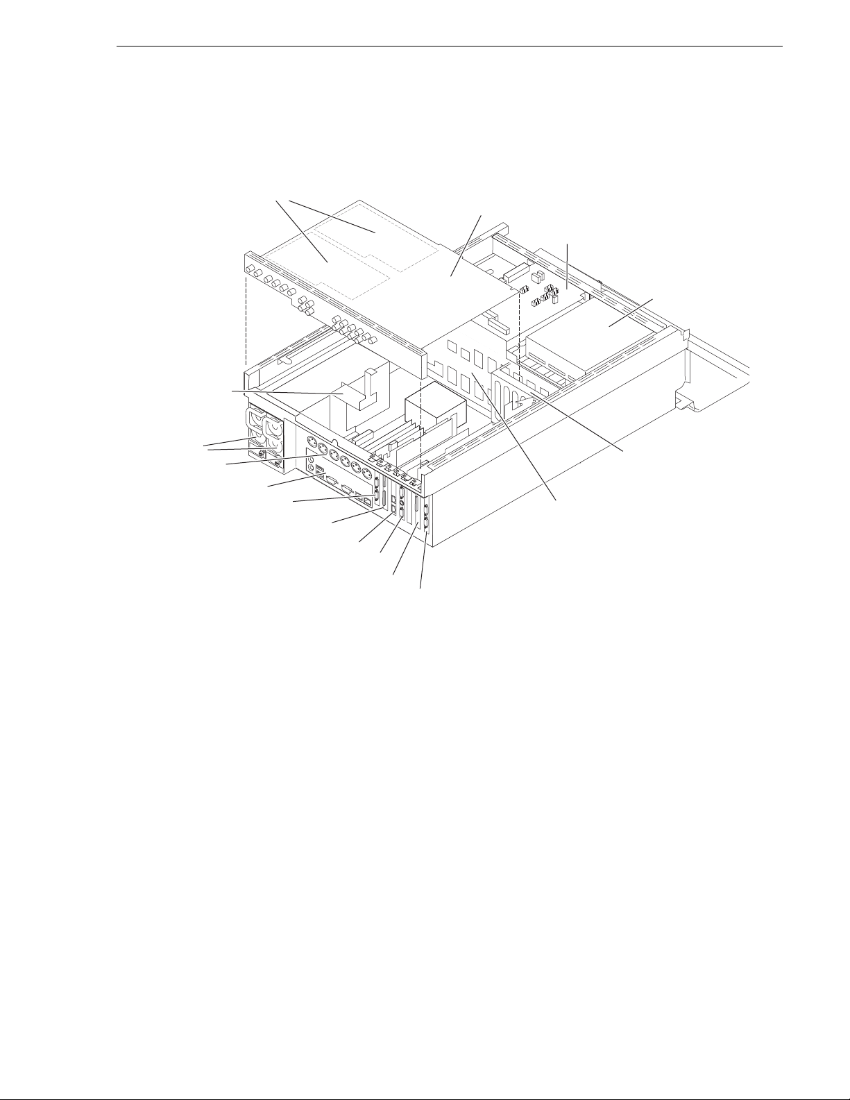
K2 Media Client orientation
The following illu strat ions s how the l ocati on of Fi eld Repl aceab le Un its (F RUs) and
other components in the K2 Media Client. For clarity, illustrations of internal
components are shown with the top cover removed and no cabling displayed. Note
that the RTP board and the Dual Ethernet adapter are in different lo cations in differe nt
models.
Front view components
DVD drive
Fan module
Front panel
RAID drives
Front bezel
20 K2 Media Client Service Manual July 28, 2008
Page 21
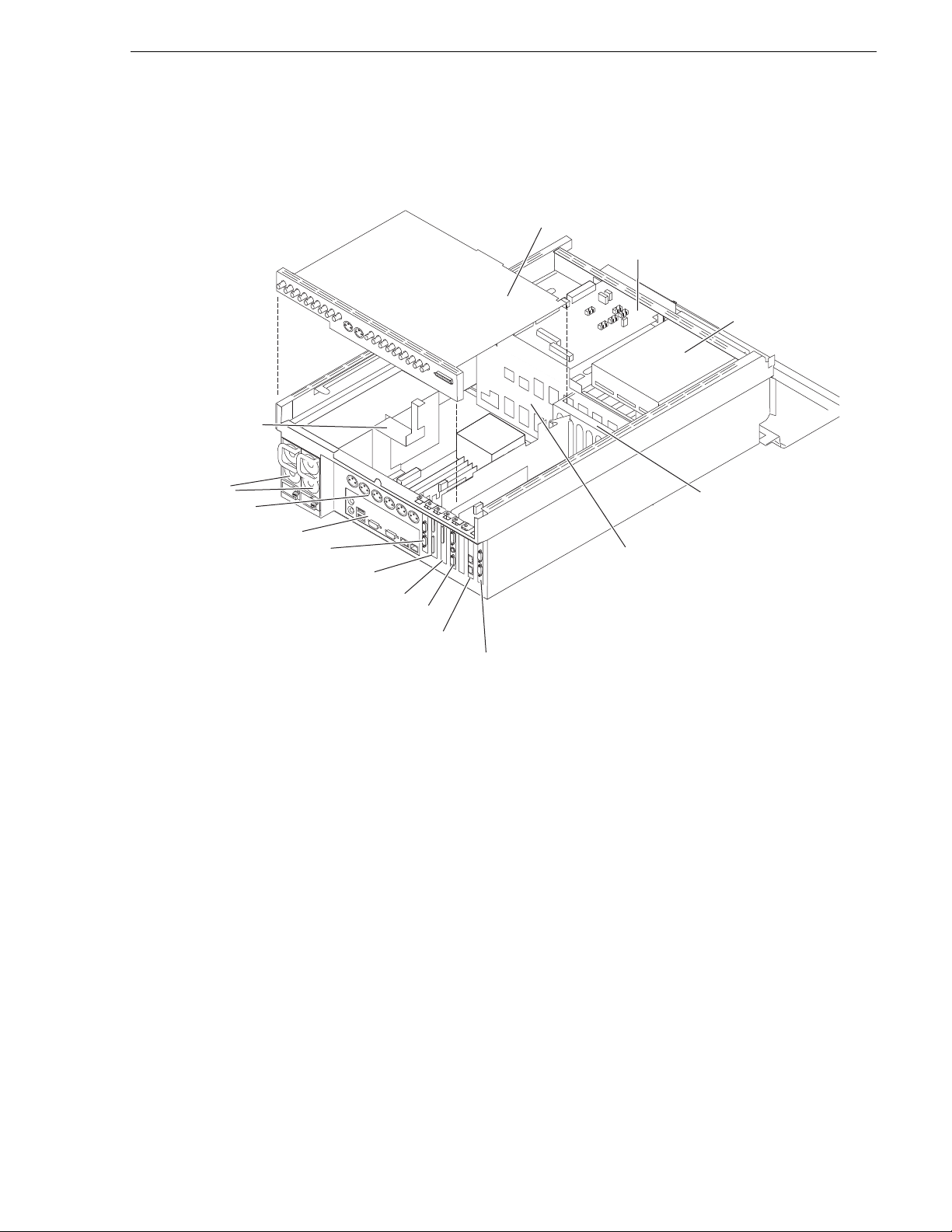
Rear view components SDA-00 model
Codec board
SCSI interface
board
DVD drive
Center support
RS-422 board*
RS-422 board*
RS-422 configuration varies.*
XLR board
Power supplies
Motherboard
Rear card guide
Dual Ethernet board
(optional)
SCSI controller adapter
RTP board
Graphics board
SCSI backplane
Rear view components SDA-00 model
July 28, 2008 K2 Media Client Service Manual 21
Page 22
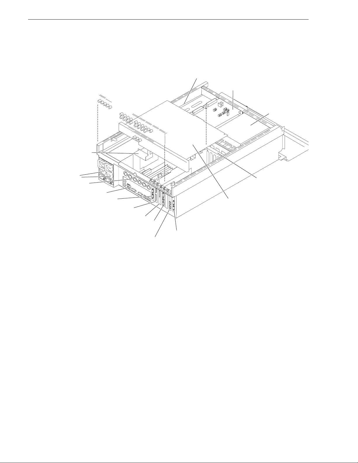
Chapter 1 Product Description
Codec board
SCSI interface
board
DVD drive
Center support
RS-422 board*
RS-422 board*
XLR board
Power supplies
Motherboard
Rear card guide
Dual Ethernet board
SCSI controller adapter
RTP board
Graphics board
SCSI backplane
RS-422 configuration varies.*
Rear view components SD-00 model
22 K2 Media Client Service Manual July 28, 2008
Page 23
Rear view components HD-00 model
Codec board
Mezzanine boards
(under codec board)
SCSI interface
board
DVD drive
Center support
RS-422 board*
RS-422 board*
XLR board
Power supplies
Motherboard
Rear card guide
RTP board
SCSI controller adapter
Dual Ethernet board
Graphics board
SCSI backplane
RS-422 configuration varies.*
Rear view components HD-00 model
July 28, 2008 K2 Media Client Service Manual 23
Page 24

Chapter 1 Product Description
FRU functional descriptions
The Field Replaceab le Units (FRU s) describ ed in this se ction are as follows:
• “Base chassis”
• “Fan module”
• “RAID drives”
• “Power supplies”
• “Removable media d r ives”
• “Codec board”
• “Mezzanine boards”
• “RTP board”
• “XLR board”
• “RS-422 adapters”
• “Dual Ethernet adapter”
• “Graphics board”
• “SCSI controller ada pter”
• “SCSI interface board”
• “SCSI backplane”
• “CPU motherboard”
For procedures, refer to Chapter 5, Removing and repl aci ng FRUs .
Base chassis
For some serious sys tem fault s or for mechani cal damage , the entire K2 Media Clien t
can be replaced as a base chassis FRU. Refer to “Replacing a K2 Media Client” on
page 80.
Fan module
The fan module has three fa ns and pr ovides cooli ng for t he K2 Media Client cha ssis.
Air intake is from the front of the K2 Media Client and outflow is through the rear.
The fan module is accessed behind the front bezel.
Refer to “Fan module removal” on page 105 for procedures.
RAID drives
There are 12 slots for RAID drives in the K2 Media Client. They are located behind
the fan module in the front of the unit. Internal storage model s have two RAID drives
for system data and five or ten RAID drives for medi a storage. Ext ernal sto rage units
have only the two RAID drives for system data.
24 K2 Media Client Service Manual July 28, 2008
Page 25

The two RAID 1 drives for system dat a form one LUN and the RAID drives for medi a
storage are configured as RAID 1 or RAID 0. Each LUN appears to the operating
system as a single disk .
In internal storage models, media data is written or “striped” across the media disks
in a continuous fashion, which makes the disks a “stripe group”. This media stripe
group appears as the V: drive to the Windows operating system.
The system disk has a C: partition for application and operating system files, a D:
partition for th e media fil e system, databas e, and configur ation informat ion, and an E:
partition for recovery images.
When configured as RAID 1, yo u can remove and replace a RAI D drive while t he K2
Media Client is operational. Refer to “RAID disk removal” on page 107 for
procedures.
Power supplies
The K2 Media Client has red undant (two) po wer supplies. The power suppli es can be
accessed from the re ar of the un it. You can re move and re place a power supply while
the K2 Media Client is oper ational. Each power suppl y has a fan with automatic speed
control and statu s LEDs that i ndicate curre nt state and health. Refer to “Power supply
problems” on page 91 for LED descriptions. The power supply has protecti on for over
voltage, over current, and short circuits.
Power supplies
Refer to “Power supply removal” on page 107 for procedu res.
Removable media drives
The K2 Media Client uses a standard remova ble media drive similar to those fo und in
desktop PCs. The drive is accessed behind the front bezel. The drive uses standard
Windows drivers for e asy plug-and- play insta llation. K2 Media Client options for the
removable media drive is as follows:
• One standard CD drive.
Refer to “Removable media drive removal” on page 111 for procedures.
Codec board
The codec board is ori ented horiz ontally acr oss the rear of the K2 Media Client
chassis. It provides the majority of the K2 Media Client’s media-related input and
output connectors on the rear panel. This board hosts the circuits responsible for
encoding/decoding video and processing audio and timecode. It is connected to the
motherboard via the RTP board.
The SDA-00 model, the SD-00 model, and the HD-00 model each use a different
codec board. The codec board in the HD-00 model can also host the mezzanine
boards, as described below.
Refer to “Codec board removal” on page 112 for procedures.
July 28, 2008 K2 Media Client Service Manual 25
Page 26

Chapter 1 Product Description
Mezzanine boards
There are two types of mez zanine boards : an encoder mezzanine board a nd a decoder
mezzanine board. Th e codec board i n the HD-00 K2 Medi a Client can hos t one or two
mezzanine boards of either type, so the number and typ e of mezzanine boa rd s on the
codec board determines the fixed channel configuration of the HD-00 K2 Media
Client model. The encoder mezzanine board provides one record channel, while the
decoder mezzanine board provides one play channel.
Refer to “Codec board removal” on page 112 for procedures.
RTP board
This Real Time Processor (RTP) board pr ovi des a dedic ate d rea l ti me proc ess or and
connections for medi a access an d processing . It functi ons as a rise r board, conn ecting
to the PCI slot below and the Codec board above.
Refer to “RTP board removal” on page 115 for procedures.
XLR board
The XLR Board provides XLR connectors at the K2 Media Client rear panel. It is
primarily an exten sion o f the codec bo ard t o all ow the space an d orient ation re quire d
for XLR connections. On the SDA-00 model, the XLR connections are used for
analog audio and LTC. On other models, t he XLR connections are only used for LTC.
The XLR board is connected via cable to the codec board.
Refer to “XLR board removal” on page 124 for procedures.
RS-422 adapters
RS-422 configuration varies, as follows:
• A K2 Media Client with a Type III motherboa rd has RS- 422 adapte rs in rear panel
slots 1 and 7. A K2 Media Client with a Type I mot her board has RS-422 adapters
in rear panel slots 3 and 7. Each a dapter is connect ed vi a a n internal USB cable t o
the motherboard, so while a RS-422 adapter does occupy a rear panel slot, it does
not plug into a PCI bus. Each adapter provides two RS-422 ports for connecting
equipment for remote control of the K2 Media Client.
• A K2 Media Client with a Type II motherboard has one RS-422 adapter. The
adapter is connected via PCI slot to the motherboard. The adapter includes an
external interface with eight ports. On the external interface, ports 1–4 are active.
This provides the four ports for connecting equipmen t for remote control of the K2
Media Client.
Refer to “RS-422 adapter removal” on page 119 for procedures.
Dual Ethernet adapter
The dual Ethernet adapter provides two Gigabit Ethernet ports. The dual Ethernet
adapter plugs into one of the standard P CI slots on the motherboar d. On some models
the dual Ethernet adapter is optional.
Refer to “Dual Ethernet adapter removal” on page 122 for procedures.
26 K2 Media Client Service Manual July 28, 2008
Page 27

Graphics board
This board provides enhanced performance for screen graphics and a connection for
a VGA monitor. The graphics board plugs into one of the standard PCI slots on the
motherboard.
Refer to “Graphics board removal” on page 121 for procedures.
SCSI controller adapter
This board provides the SCSI c ontroller fu nctionalit y for the internal RAID disks. On
internal storage models, both system and media data require this RAID controller
functionality, as both are stored on the internal RAID disks. On external storage
models, only the system data requi res RAID contr ol ler func ti onality, as the media is
stored on the K2 Storage System or on direct-connect RAID storage. The SCSI
controller adapter plugs into one of the standard PCI slots on the motherboard.
Refer to “SCSI controller adapter removal” on page 123 for procedures.
SCSI interface board
This board provides the SCSI interface for the RAID drives. It monitors and reports
the status of the RAID drives , the chassis fans, and the power suppli es. It also controls
the individual RAID status LEDs and the front panel Power and Service LEDs. It is
mounted horizontally in the front of the unit, above the RAID drives. It provides a
front panel USB connection.
Graphics board
Refer to “SCSI interface board removal” on page 110 for procedures.
SCSI backplane
This board provides the connection for each RAID drive. It is mounted in the center
of the unit.
Refer to “SCSI backplane removal” on page 117 for procedures.
CPU motherboard
The K2 Media Client uses an extended ATX motherboard with an Intel Xeon
processor. The motherboard provides PCI board slots, built in Gigabit Ethernet, and
USB ports. The Type I motherboard provides USB 1.1 ports. The Type II and Type
III motherboard provides USB 2.0 ports. It is located in the bottom rear of the K2
Media Client chassis.
Refer to “CPU motherboard replacement” on page 126 for procedures.
July 28, 2008 K2 Media Client Service Manual 27
Page 28
Chapter 1 Product Description
!
Status indicators
The following sections describe the visual and audible indicators that communicate
the current operating status and system health of the K2 Media Client.
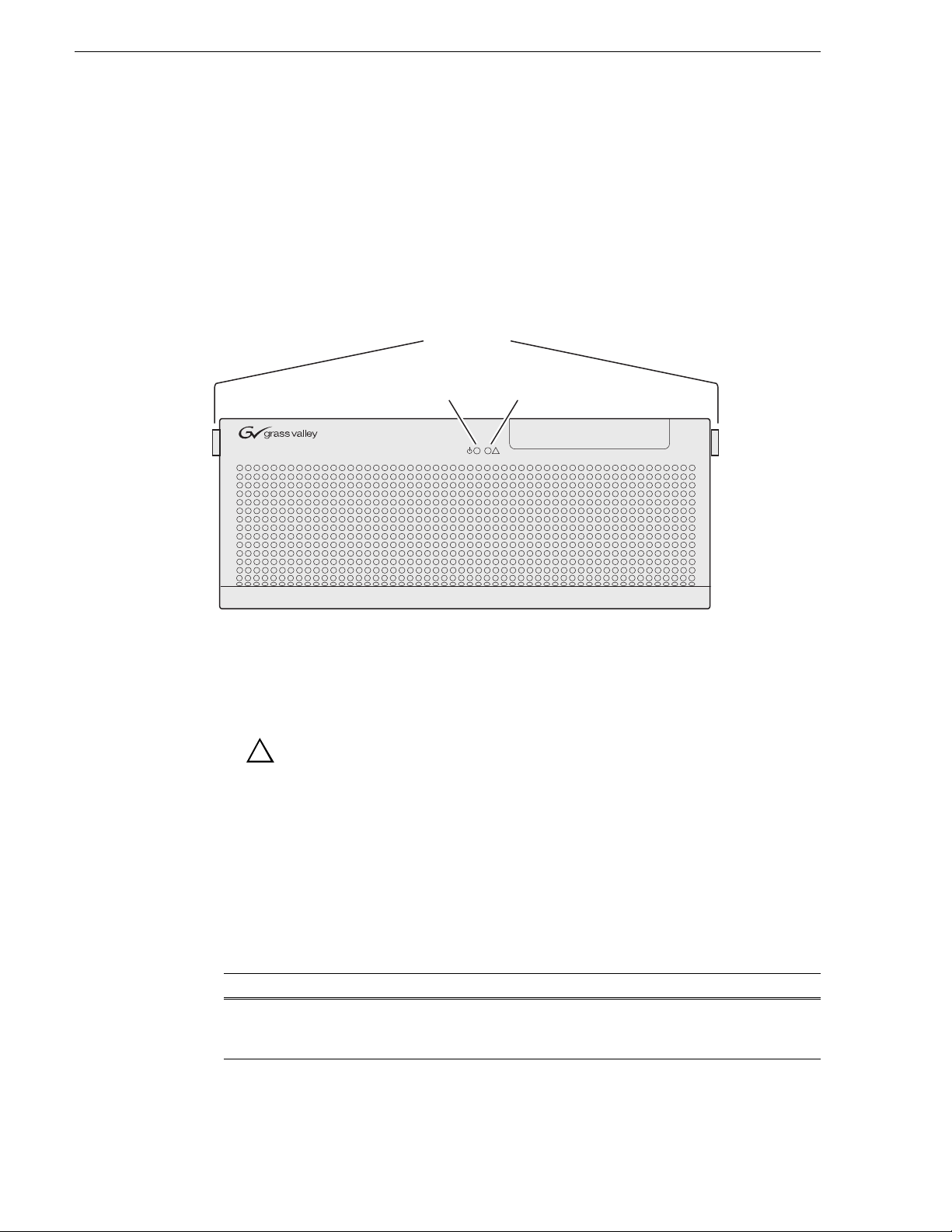
Front panel indicators
You can see the front panel LEDs while the front bezel is closed or open.
Bezel Release
Buttons
Power LED
This LED indicates st atus as foll ows:
Off: The standby switch is set to Off and the K2 Media Client is not operational.
Steady on (green): The standby switch is set to On a nd the K2 Medi a Clien t is ei ther
in the startup process or has competed the startup process and is operational.
Power
LED
Service
LED
!
WARNING: The power standby switch does not turn off power to the
system. To turn power off the syst em must be d i sconnected from the
power source.
Service LED
The following table explains the status conditions indicated by the different Service
LED behaviors. If two or more status conditions occur simultaneously, the L ED
displays the behavior for the highest priority condition.
LED behavior Status Condition Priority
Flashing pattern alternating
Yellow/Green/Red/Off twice a
second
28 K2 Media Client Service Manual July 28, 2008
Identify — The K2 Medi a Client is being dir ected to
identify itself by NetCentral or some other
application.
1
Page 29

Rear panel indicators
LED behavior Status Condition Priority
Solid Red Global failure — The K2 Media Client system
software has detected a critical error or failure that
impacts record/play operations.
2
Solid Yellow Warning — The K2 Media Client syste m software has
Flashing Yellow pattern three time
a second.
Flashing pattern alternating
Yellow/Green once a second.
Off Normal — The K2 Media Client is healthy and
RAID drive indicators
Each RAID drive has LEDs t hat indicate status. You must re move the fan module to
see these LEDs. The following table explains the status conditions indicated by the
different LED behaviors. If two or more status conditions occur simultaneously, the
LED displays the behavior for the highest priority condition.
LED behavior Status Condition Priority
Flashing pattern alternating
Yellow/Green/Red/Off twice a
second
Both Red and Green LED off Drive is not fully engaged in slot. 2
detected a problem that requires atte ntion but does n ot
immediately impact record/play operations. For
example, a fan or power supply has failed but its
redundant partner is maintaining functionality.
Drive failure — An internal RAID drive has failed. If
RAID 1, the failure does not immediately i mpact
record/play operations. The redundant partner RAID
drive is maintaining functionality.
Drive rebuild — If RAID 1, an internal RAID drive is
rebuilding.
operating normally.
Identify — The RAID drive is being directed to
identify itself by Storage Utility or some other
application.
3
4
5
5
1
Red LED is ON solid. Green LED
is off.
Flashing pattern alternating
Yellow/Green once a second
Red LED is off. Green LE D
displays pulsing patterns.
Fault — The SCSI controller has marked the drive as
faulty.
Rebuild — The SCSI controller has marke d the drive
as rebuilding.
Normal drive activity — The RAID drive is healthy
and disk access is underway. (Both LEDs are off when
there is no disk activity.)
3
4
5
Rear panel indicators
The following indicators are visible from the rear panel view.
July 28, 2008 K2 Media Client Service Manual 29
Page 30
Chapter 1 Product Description
Yellow LED
Green/Orange LED
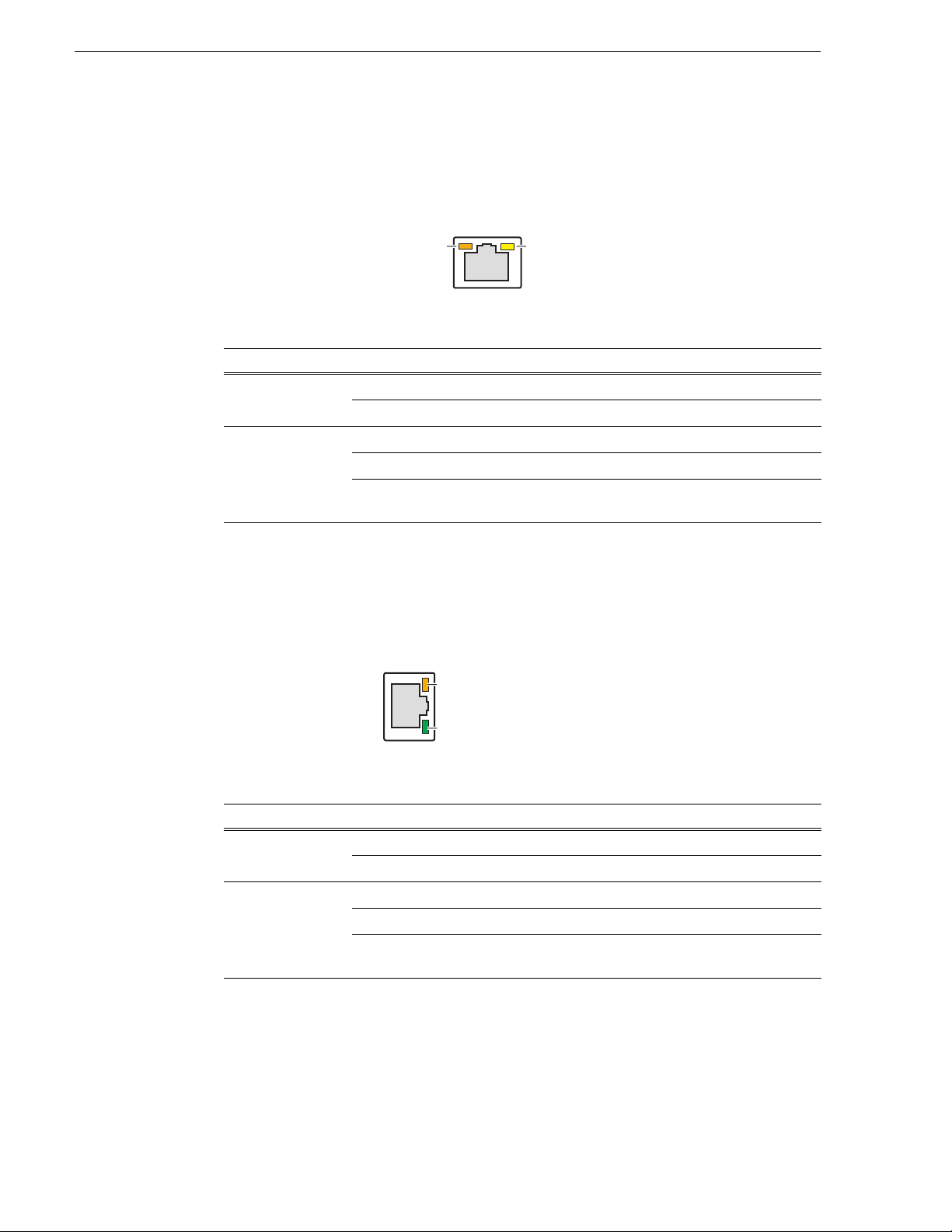
Motherboard LAN connector indicator codes
The motherboard has two RJ-45 LAN conne ctors that include integrat ed status LEDs .
The LEDs are oriented as follows:
The meanings of the LED states are described in the following table:
LED LED state Condition
Green/Orange Green On 100 MHz.
Yellow Off LAN link is not established
Orange On 1 GHz
On (steady state) LAN link is established
On (brighter and puls ing) The computer is communicating with anoth er
computer on the LAN.
If a LAN connector is faulty, you must replace the motherboard.
Dual Ethernet adapter LAN connector indicator codes
The dual Ethernet adapter has two RJ-45 LAN connectors that include integrated
status LEDs. The LEDs are oriented as follows:
Green/Orange LED
Green LED
The meanings of the LED states are described in the following table:
LED LED state Condition
Green/Orange Green On 100 MHz.
Orange On 1 GHz
Green Off LAN link is not established
On (steady state) LAN link is established
On (brighter and puls ing) The computer is communicating with anoth er
computer on the LAN.
30 K2 Media Client Service Manual July 28, 2008
If a LAN connector is faulty, you must replace the dual Ethernet adapter.
Page 31

Power supply indicators
Each power supply has a LED that indicates status.
Interpret the power supply LED as follows:
LED behavi or Power supply co ndition
Green ON Normal operation
OFF Power supply is defective or not fully connected.
System beep codes
Status LEDs
The Service LED on the front of the K2 Media Client also indicates power supply
status. Refe r to “Service LED” on page 28.
If the power source and the power cord are OK and the status lights on the power
supply indicate a problem, replace the power supply. Refer to “Power supply
removal” on page 107.
System beep codes
If there are no errors present the K2 Media Client does not emit any audible beeps
during startup process or otherwise. When a recoverable type of error occurs during
Power On Self Test (POST), the motherboard BIOS will display a POST code that
describes the problem. Ref er to “ BIOS POST message s” on page 34. The BIOS may
also issue one of the following beep codes:
Error Beep Code Description
One long and two short beeps Video configuration error
One continuous long beep No memory detected
These beep codes indicate a problem with the motherboard.
July 28, 2008 K2 Media Client Service Manual 31
Page 32

Chapter 1 Product Description
32 K2 Media Client Service Manual July 28, 2008
Page 33

Chapter 2
System Messages
Topics in this section include the following:
• “About system messages” on page 34
• “BIOS POST messages” on page 34
• “Critical system startup messages” on page 38
• “Viewing AppCenter system status messages” on page 38
July 28, 2008 K2 Media Client Service Manual 33
Page 34

Chapter 2 System Messages
About system me ss a ges
The following messages are displayed to indicate K2 Media Client status:
• Normal BIOS messages — During normal st artup processes these messa ges can be
observed on a locally connected VGA monitor. Refer to “Motherboard BIOS
startup information” on page 85, “SCSI controller adapter BIOS startup
information” on page 86, and “Motherboard BIOS startup summary screen” on
page 87.
• BIOS POST error messages — If there is a pr oblem these messages are di spl ayed
on a locally connected VGA monitor startup processes. Refer to “BIOS POST
messages” on page 34.
• K2 Media Client startup messages — As AppCenter opens the K2 Media Client
determines if system hea lt h is adequate by checking criti ca l sub sys te ms . A dialog
box is displayed that indicates progress and displays messages. Refer to “Critical
system startup messages” on page 38.
• Status bar and StatusPane messages — During normal operation AppCenter
displays system status mess ages on the status bar. From the stat us bar you can open
the StatusPane to see both current and previous messages. You can observe these
messages in AppCenter on a locally connected VGA monitor or on a network
connected control point PC. Refer to “Viewing AppCenter system status
messages” on page 38.
• Storage Utility mess age s — Whil e y ou a re usi ng Storage Utility, p op- up message
boxes inform you of the current status of the storage system.
• NetCentral messages — If you are monitoring the K2 Media Client with
NetCentral, the NetCent ral interface displa ys a variety of messages an d other status
indicators. Refer to the NetCentral Help menu for a complete list of all the
messages that a monitored device can send.
BIOS POST messages
During the Power On Self Test (POST), the motherboard BIOS checks for problems.
If a problem is found, the BIOS activ ate s an alar m or dis plays a messag e. For s tart up
troubleshooting ref er to “Step 4: Identify problems using the startup sequence” on
page 82.
The following is a list of BIOS POST messages.
BIOS Message Description
Failure Fixed Disk Fixed disk is not worki ng or not configur ed
Stuck key Stuck key on key board.
properly. Check to see if fixed disk is attached
properly. Run Setup. Fin d out if the fixed-disk type
is correctly identified.
Keyboard error Keyboard not working.
34 K2 Media Client Service Manual July 28, 2008
Page 35

BIOS POST messages
BIOS Message Description
Keyboard Controller Failed Keyboard controller failed test. May require
replacing keyboard controller.
Keyboard locked - Unlock key swit ch Unlock the system to proceed.
Monitor type does not match CMOS -
Run SETUP
Shadow Ram Failed at offset: nnnn Shadow RAM failed at offset nnnn of the 64k
System RAM Failed at offset: nnnn System RAM failed at offset nnnn of in the 64k
Extended RAM Failed at offset: nnnn Extended memory not working or not configured
System battery is dead - Replace and
run SETUP
System CMOS checksum bad Default configuration used
System timer error The timer test failed. Requires repair of system
Real time clock error Real-Time Clock fails BIOS hardware test. May
Check date and time settings BIOS found date or time out of range and reset the
Previous boot incomplete - Default
configuration used
Memory Size f ound b y POST dif fered
from CMOS
Monitor type not correctly identified in Setup
block at which the error was detected.
block at which the error was detected.
properly at offset n nnn.
The CMOS clock battery indicator shows the
battery is dead. Replace the batter y and run Setup
to reconfigure the system.
System CMOS has been corrupted or modified
incorrectly, perhaps by an application program
that changes data stored in CMOS. The BIOS
installed Default Setup Valu es. If y ou do no t wan t
these values, enter Setup and enter your own
values. If the error persists, check the system
battery or contac t your dealer.
board.
require bo ard repair.
Real-Time Clock. May require setting legal date
(1991-2099).
Previous POST did not complete successfully.
POST loads default values and offer s to run Setup.
If the failure was caused by incorrect values an d
they are not corrected, the next boot will likely fail.
On systems with control of wait states, improper
Setup settings can also terminate POST and cause
this error on the next boot. Run Setu p and verify
that the waitstate configuration is correct. This
error is cleared the next time the system is booted.
Memory size found by POST differed from
CMOS.
Diskette drive A error Drive A: or B: is present but fails the BIOS POST
Diskette drive B error
Incorrect Drive A type - run SETUP Type of floppy drive A: not correctly identified in
Incorrect Drive B type - run SETUP Type of floppy drive B: not correctly identified in
diskette tests. Check to see that the drive is defined
with the proper diskette ty pe in S et up and t ha t th e
diskette drive is attached correctly.
Setup.
Setup.
July 28, 2008 K2 Media Client Service Manual 35
Page 36

Chapter 2 System Messages
BIOS Message Description
System cache error - Cache disabled RAM cache failed and BIOS di sabled the cache.
CPU ID: CPU socket number for Multi-Processor error.
EISA CMOS not writeable ServerBIOS2 test error: Cannot write to EISA
DMA Test Failed ServerBIOS2 test error: Cannot write to extended
Software NMI Failed ServerBIOS2 test error: Cannot generate software
Fail-Safe Timer NMI Failed ServerBIOS2 test error: Fail-Safe Timer takes too
device Address Conflict Address conflict for specified device.
Allocation Error for: device Run ISA o r E ISA Configu ratio n Utility to resolv e
On older boards, check the cache jumpers. You
may have to replace the cache. See your dealer. A
disabled cache slows system performance
considerably.
CMOS.
DMA (Direct Memory Access) registers.
NMI (Non-Maskable Interrupt).
long.
resource conflict for the specified device.
CD ROM Drive CD ROM Drive identified.
Entering SETUP… Starting Setup program
Failing Bits: nnnn The hex number nnnn is a map of the bits at the
RAM address which failed th e mem ory te st. Ea ch
1 (one) in the map indicates a failed bit. See errors
230, 231, or 232 abov e for offset address of the
failure in System, Extended, or Shadow memory.
Fixed Disk n Fixed disk n (0-3) identified.
Invalid System Configuration Data Problem with NVRAM (CMOS) data.
I/O device IRQ conflict I/O device IRQ conflict error.
PS/2 Mouse Boot Summary Screen: PS/2 Mouse installed.
nnnn kB Extended R AM Passed Where nnnn is the am ount of RAM in kilo bytes
successfully tested.
nnnn Cache SRAM Passed Where nnnn is the amount of system cache in
kilobytes successfully tested.
nnnn kB Shadow RAM Passed Where nnnn is the amount of shadow RAM in
kilobytes successfully tested.
nnnn kB System RAM Passed Where nnnn is the amount of system RAM in
kilobytes successfully tested.
One or more I2O Block Storage
Devices were excluded from the Setup
Boot Menu
There was not enough room in the IPL table to
display all insta lled I2O blockstorage devices.
Operating system not found Operating system cannot be located on either drive
A: or drive C:. Enter Setup and see if fixed disk
and drive A: are properly identified.
36 K2 Media Client Service Manual July 28, 2008
Page 37

BIOS POST messages
BIOS Message Description
Parity Check 1 nnnn Parity error found in the system bus. BIOS
attempts to locate the address and display it on the
screen. If it cannot locate the address, it displays
????. Parity is a method for checking errors in
binary data. A parity error in dicates that some data
has been corrupted.
Parity Check 2 nnnn Parity error found in the I/O bus. BIOS attempts to
locate the address and display it on the screen. If it
cannot locate the address, it displays ????.
Press <F1> to resume, <F2> to Setup,
<F3> for previous
Press <F2> to enter Setup Optional message displaye d during POST . Can be
PS/2 Mouse: PS/2 mouse identified.
Run the I2O Configuration Utility One or more unclaimed block storage devices have
System BIOS shadowed System BIOS copied to shadow RAM.
UMB upper limit segment address:
nnnn
Video BIOS shad ow e d Video BIOS successfu lly co pied to shadow R AM.
Displayed after any recoverable error message.
Press <F1> to start th e boot process or <F2> to
enter Setup and change the se ttings. Press <F3 > to
display the previous screen (usually an
initialization error of an Option ROM, i.e., an
add-on card). Write down and follow the
information shown o n the screen.
turned off in Setup.
the Configuration Request b it set in the LCT. Run
an I2O Configuration Utility (e.g. the SAC ut ility).
Displays the address nnnn of the upper lim it of
Upper Memory Blocks, indicating released
segments of the BIOS which can be reclaimed by
a virtual memory manager.
July 28, 2008 K2 Media Client Service Manual 37
Page 38

Chapter 2 System Messages
Critical system startup messages
The following messages appear in the AppCenter system startup message box as
critical subsystems are checked during K2 Media Client startup processes. If one of
these critical subsystems fails, the K2 Media Client is rendered inoperable and the
failure me ssage appears.
Critical subsystem check messages Failure messages
System Startup Startup error
Checking hardware… Hardware fault
Checking media disks… One or more media disks failed to initiali ze
Checking file system… No file system is running
Checking database… Database fault
Missing or bad hardware
The real time processor is not functioning correctly
Missing or bad hardware
Missing or bad SQL database
Checking real-time system status… The real-time system failed to initialize
Updating configuration… Failed to synchron iz e config ura tio ns
Starting services… Unable to communicate with <service name>
Viewing AppCenter system status messages
System status mess ages are di splayed in the AppCenter status ba r. There ar e two type
of system status messages, as follows:
• Channel status mes sages — I n normal o peration, this type of message displays the
current operating status of the selected channel.
• System error messages — If a problem develops with the system software or a
hardware subsystem, this type of message is displayed for approximately 5
seconds. Afterward, the display returns to the channel status message and the error
message is written to t he status log file. Whe n a message is written to the status log,
a Status Icon indicates the severity of the message.
38 K2 Media Client Service Manual July 28, 2008
Page 39

Viewing system status messages
Status Messages
Protocol
Monitor
Button
Transfer
Monitor
Button
StatusPane
Button
Player 2: Playing 'List_10', 'Section 1', 'Clip_2'
System status messages appear in the AppCenter status bar, which is located across
the bottom of the AppCenter window, and consists of a message area, several tool
buttons, and a status icon. The button icons appear only when the related function is
active. In the position of the StatusPane button, status icons appear.
The status icon changes depending on the status of the current status message.
Icon Name Description
Information A recent information message is present.
Viewing system status messages
Warning There is at least one warning message, and no alert messages.
Alert There is at least one uncleared alert message.
Current and previous system status messages can be viewed in the StatusPane. To
open the StatusPane, click
Help | System Status.
July 28, 2008 K2 Media Client Service Manual 39
Page 40

Chapter 2 System Messages
Status icon
Date Time The machine that
reports this message
The subsystem that
reports this message
The StatusPane is used to view detailed system messages including status, warning,
and error messages. System stat us messages provid e status i cons and a d escri ption of
the status event reported by the message. If there is a problem, a corrective action is
indicated. Use these messages along with Chapter 4, Troubleshooting problems to
determine if a service procedure is necessary.
If you have a remote AppCenter Channel Suite with channels from multiple K2 Media
Clients, the messag es from the diff erent machines are combined in the St atusPane that
you view from the Cha nnel Suite. To help you determine which machin e is generating
a message, each message lists the machine name.
Copying StatusPane messages to the clip board
1. Select the message or messages in the StatusPane.
2. Click
Copy.
After copying the message, it can be pasted using standard Windows techniques.
Clearing messages
Clearing messages from the St atusPane removes them from t he loggin g databas e and
the StatusPane. This also clears the state of the subsystem i ndicators so they no longer
display the alert and warning symbols.
1. Open the StatusPane, then click
Clear.
2. When a message prompts you to confirm, click
Yes.
All messages are removed from the StatusPane and logging database.
40 K2 Media Client Service Manual July 28, 2008
Page 41

Chapter 3
Service Procedures
Topics in this section include the following:
•“Exporting log files” on page 41
•“Replacing a RAID 0 drive” on page 43
•“Replacing a RAID 1 drive” on page 43
•“Restoring network configuration” on page 44
•“Configuring Event Viewer” on page 57
•“Checking services” on page 58
•“Checking pre-installed software” on page 61
•“Configuring NVRAM” on page 62
•“Making motherboard CMOS settings” on page 65
•“Rescanning PCI slots” on page 67
•“Using recovery disk images” on page 67
•“Installing the Fibre Channel card driver” on page 78
•“Replacing a K2 Media Client” on page 80
Exporting log files
The procedures in this section describe how to export log files from the K2 Media
Client. The log files can include the following:
• All applications messages
• The Windows Event Log
• Logs from the media database.
• Dr. Watson messages.
The exported log files are combined in a ZIP file. The ZIP file can be sent to Grass
Valley product support whe re the y can analyze the logs to det ermi ne t he operational
status of your K2 Media Client.
NOTE: ExportLog does not export StatusPane messages. To capture StatusPane
messages, refer to the “Copying StatusPane messages to the clip bo ard” on page 40.
Use one of the following procedures to export the logs.
Exporting log files from AppCenter workstation
1. In AppCenter workstation click
opens.
2. Click the
July 28, 2008 K2 Media Client Service Manual 41
Logs tab.
System | Export Log. The Export Log dialog box
Page 42

Chapter 3 Service Procedures
3. Select the logs to export.
4. Click the
Destination tab.
5. Browse to a location for saving the log file.
6. Name the log file.
7. Click
8. When the export process is complete, and message confirms success. Click
Export. A progress bar appears.
OK and
close the Export Log dialog box to continue.
9. Find the log file at the specified location.
42 K2 Media Client Service Manual July 28, 2008
Page 43

Exporting log files using the Windows command line
This procedure allows you to export log files even if AppCenter does not start
properly. It uses the Windows command prompt.
1. If you have not already done so, connect a mouse and keyboard to the K2 client
system.
Replacing a RAID 0 drive
2. In the Windows task bar, select
3. Type the following in the Run dialog box, then click
c:\profile\exportlog
The ExportLog dialog box is displayed.
4. Continue with the procedure “Exp orting log fil es from AppCenter wo rkstation” on
page 41, starting with step 2.
Start | Run.
Replacing a RAID 0 drive
If configured as RAID 0 (media drives only), when one drive fails, all media is lost.
To replace a RAID 0 drive, do the following:
1. Unbind the LUN that has the failed drive. Do not unbind the system drive RAID 1
LUN.
2. Remove the failed drive from the K2 Media Client chassis.
3. Insert the replacement drive in the K2 Media Client chassis.
4. Restart the K2 Media Client.
5. Using Storage Utility on the K2 Media Client, bind disks as RAID 0.
6. Restart the K2 Media Client.
7. Using Storage Utility on the K2 Media Client, make a new file system.
OK.
8. Restart the K2 Media Client.
Always use the Storage Utility to physically identify the failed drive. Accidently
removing the wrong drive can destroy data. To identify a drive, in Storage Utility
right-click the drive and select
Refer to the K2 Media Client System Guide for Storage Utility procedures.
Refer to “RAID disk removal” on page 107 for the mechanical procedure for
removing and inserting a drive.
Identify. This causes the disk lights to flash.
Replacing a RAID 1 drive
If configured as RAID 1, you’ll repair the system by replacing the drive as soon as
possible. The two RAID drives that make the system drive are always RAID 1. You
can replace a single RAID 1 drive (either system or media) while continuing media
operations.
July 28, 2008 K2 Media Client Service Manual 43
Page 44

Chapter 3 Service Procedures
Always use the Storage Utility to physically identify the failed drive. Accidently
removing the wrong drive can destroy data. To identify a drive, in Storage Utility
right-click the drive and select
the K2 Media Client System Guide for Storage Utility procedures.
Before removing the dis k modul e, you shoul d use Stor age Uti lity to di sab le the di sk.
Refer to “RAID disk removal” on page 107 for the mechanical procedure for
removing and inserting a drive.
On inserting a RAID 1 replacement drive, if disk access (record/play operations) is
underway, the RAID controller automatically starts rebuilding the drive. You can
verify rebuild status by looking at the drive LED or by looking at the Service LED.
Refer to “Front panel indicators” on page 28. If there is no media access currently
underway, you can use Storage Utility to force-start the rebuild process.
You can also ch eck disk sta tus in the Storage Utili ty by select ing the disk module icon
in the device tree. Status is reported in the right-hand pane. On completion, the disk
drive status ch anges fr om Rebuildi ng to Onli ne. You ma y need to refres h the Stor age
Utility display. You can also open the Progress dialog box, by clicking
Report
.
Restoring networ k configuration
Identify. This causes the disk lights to flash. Refer to
View | Progress
When you receive an internal storage K2 Media Client from the factory, the four
Gigabit Ethernet ports are DHCP enabled and there is a loopback adapter installed.
There is no teaming on an internal storage K2 Media Client.
When you receive a di rect-connec t storage K2 Media Client from the f actory, the t wo
Gigabit Ethernet ports are DHCP enabled and there is a loopback adapter installed.
There is no teaming on a direct-connect storage K2 Media Client.
On stand-alone storage (either internal or direct-connect storage) K2 Media Clients,
do the following to restore the network configuration:
• Use standard Windows procedures to reset the ports to DHCP enabled.
• “Install the loop-back adapter”
• “Identify adapters”
• “Set Rx/Tx Descriptors Value”
• “Reorder adapters”
When you receive an shared storage K2 Media Client from the factory, it has
specialized network configuration, including a loopback adapter and two of the four
Gigabit Ethernet ports configured as a teamed pair.
On shared st orage K2 M edia Client s, do the following to re store the ne twork
configuration:
• “Install the loop-back adapter”
• “Identify adapters”
• “Set Rx/Tx Descriptors Value”
• “Create the Control Team”
44 K2 Media Client Service Manual July 28, 2008
Page 45

• “Name team”
• “Reorder adapters”
Install the loop-back adapter
When you receive a K2 Media Client from the factory, it has a loop-back adapter
installed. This i s tr ue for all s torage types . Use the fo ll owing pr ocedure to re st ore th e
loop-back adapter:
Install the loop-back adapter
1. In the Windows Control Panel, open
2. Click
Yes, I have already connected the hardware, and then click Next.
3. At the bottom of the list, click
4. Click
5. Click
Install the hardware that I manually select from a list, and then click Next.
Network adapters, and then click Next.
6. In the Manufacturer box, click
7. In the Network Adapter box, click
8. Click
9. In Control Panel, go to
Next, then Finish.
Network Connections.
Add Hardware and then click Next.
Add a new hardware device, and then click Next.
Microsoft.
Microsoft Loopback Adapter, and t hen click Next.
10.Find the connection that reports itself i n the Device Name column as the loopback
adapter. Right-click on this icon and rename the connection to
11.Right-click on the Loopback icon and select
12. Select
13.Click
Internet Protocol (TCP/IP) and click the Properties button.
Use the following IP address and set the add ress to 192.168.200.200 and
Properties.
Loopback.
set the subnet mask to 255.255.255.0.
NOTE: The Microsoft Loopback Adapter must have its IP address set to
192.168.200.200. If a di fferent IP addre ss is used the sta nd-alone storage K2 Media
Client can not access its own media file system.
14.Click
15.Return to
16.On the menu bar at the top of the window, select
OK and Close to exit.
Network Connections in Control Panel.
Advanced, then Advanced
Settings…
17.On the Adapters and Bindings tab move the Loop back connect ion to the en d of the
LAN adapters in the list (leaving it above Remote Access connections).
18.Click
OK to exit.
19.Continue with the next procedure “Identify adapters”.
Identify adapters
1. Open Device Manager as follows:
a. On the Windows desktop, right- click
July 28, 2008 K2 Media Client Service Manual 45
K2 Media Client (My Computer) and selec t
Page 46

Chapter 3 Service Procedures
Manage. The Computer Management window opens.
b. In the left pane select
Device Manager. Device Manag er o pens in the right pane.
2. In Device Manager, verify that adapter names are the correct default names as
follows:
a. Expand
Network Adapters.
b. If a Type I motherboard, verify that there are four adapters listed, na med as
follows:
- Intel® PRO/1000 MT Dual Port Server Adapter
- Intel® PRO/1000 MT Dual Port Server Adapter #2
- Intel® PRO/1000 MT Dual Port Server Adapter #3
- Intel® PRO/1000 MT Dual Port Server Adapter #4
c. If a Type II or Type III motherboard, verify th at there are four adapters listed,
named as follows:
- Intel® PRO/1000 EB Network Connection with I/O Acceleration
- Intel® PRO/1000 EB Network Connection with I/O Acceleration #2
- Intel® PRO/1000 MT Dual Port Server Adapter
- Intel® PRO/1000 MT Dual Port Server Adapter #2
Sometimes adapter names chan ge due t o PNP device removal and recr eation. I f
you are having this problem, remove all network devices, then reboot and let
Windows PNP enumerate netw ork adapter s. The def ault net work names s hould
reappear numbered correctly. If the numbering is still incorrect, shut down the
K2 Media Client, remove the dual Ethernet card, then start up the K2 Media
Client. This forces the system to scan the motherboard ports first and enumerate
properly. Then shutdown the K2 Media Client, replace the dual Ethernet card,
and start up the K2 Media Client. This time the dual Ethernet card is scanned
46 K2 Media Client Service Manual July 28, 2008
Page 47

Identify adapters
and enumerated after the motherboard ports.
External storage K2 Media Clients with the optional Fibre Channel card
installed have only two adapters.
3. For each adapter name sh own, veri fy tha t th e ada pter n ame i s mapp ed cor rectl y to
a physical port, as follows:
a. Under Network adapters, right-click an adapter and select
Properties dialog box opens.
Properties. The
4. Select the
Link tab and then click Identify Adapter. The Identi fy Adapter dia log box
opens.
5. Click
July 28, 2008 K2 Media Client Service Manual 47
Start.
Page 48

Chapter 3 Service Procedures
6. Verify that the LED is blinking ne xt to the physical network por t corresp onding to
that adapter software name, as follow s:
Software adapter name
Type I Mothe r b oa r d
…MT Dual Port Server Adapter …EB Network Connection… 1st (left) port on the motherboard
…MT Dual Port Server Adapter #2 …EB Network Connection…#2 2nd (right) port on the mother board
…MT Dual Port Server Adapter #3 …MT Dual Port Server Adapter 1st (upper) port on the dual Ethernet
…MT Dual Port Server Adapter #4 …MT Dual Port Server Adapter #2 2nd (lower) port on the dual
Software adapter name
Type II and Type III Motherboard
Physical port (as viewed facing
the rear panel)
adapter
Ethernet adapter
External storage K2 Media Clients with the optional Fibre Channel card installed
do not have the dual Ethernet adapters.
7. Continue with the next procedure “Set Rx/Tx Descriptors Value”.
Set Rx/Tx Descriptors Value
All K2 Media Clients, with all storage types, sh ould be configured as in structed in the
following procedure:
1. In Device Manager, highlight and right-click the
Server Adapter
Acceleration
2. Select
Properties. The Properties dialog box opens.
(Type I MB) or the Intel® PRO/1000 EB Network Connection with I/O
(Type II and Type III MB).
Intel® PRO/1000 MT Dual Port
3. Click
4. In the Settings list, select
Advanced tab.
Performance Options, then click the Properties button.
The Performance Options dialog box opens.
5. In the Property list, select
6. In the Values field, use the up/ down a rr ows t o set the value to
Receive Descriptors.
1024. If 1024 is not
available, select a different entry in the settings list, then select back to Receive
Descriptors. This resets the values available in the Values field.
7. In the Settings list, select
8. In the Values field, set the value to
9. Click
OK to close dialog boxes and save settings.
Transmit Descriptors.
1024.
10.Repeat this procedure on the remaining Ethernet adapters.
For stand-alone storage K2 Media Clients, continue with “Reorder adapters” on
page 56.
For shared storage K2 Media Clients, continue with the next procedure “Create the
Control Team”.
48 K2 Media Client Service Manual July 28, 2008
Page 49

Create the Control Team
Only shared storage K2 Media Clients are required to have a control team, as
instructed in the following procedure. Refer to the K2 Media Client System Guide if
you want to optionally team an internal storage K2 Media Client.
Teams are not supported on external storage stand-alone K2 Media Clients with
direct-connect RAID storage .
On shared sto rage K2 Medi a Clients, the goal of teaming is to creat e a team for th e
control network. There is no team for the media (iSCSI) network. The teaming should
be set up such that the first physica l port on the mothe rboard and the fir st physical port
on the dual Ethernet adapter are teamed for control.
Prior to K2 system software release 3.2.5x in the Fal l of 200 7, there was a bug i n the
teaming software for which the work around required creating a team named “DO
NOT USE”. With release 3.2.5x., driv ers were updated and the bug was fixed . The fix
is available on K2 Media Clients shipping after the release of 3.2.5x. Earlier K2
Media Clients retain the same drivers, even if the system software is updated, and so
must use continue to use the “DO NOT USE” work around if teaming must be
reconfigured. Use the procedure appropriate for your K2 Media Client.
Create the Control Team on systems shipping before 3.2.5x
Create the Control Team
Use this procedure if the K2 Media Client ship ped from Gra ss Valley pr ior to rel ease
3.2.5x in the Fall of 2007.
1. In Device Manager, right-click
Network Connection…
(Type II and Type III MB) and select Properties. The
…MT Dual Port Server Adapter (Type I MB) or …EB
Properties dialog box opens.
2. Select the
Teaming tab.
July 28, 2008 K2 Media Client Service Manual 49
Page 50

Chapter 3 Service Procedures
3. Select Team with other adapters, then click New Team. The New Team Wizard
opens.
4. Enter DO NOT USE.
You enter this name because there is a bug in the teaming software that creates a
“phantom” entry with this name, however that entry is not usable. Continue with
this procedure to work around the bug.
Click
Next.
50 K2 Media Client Service Manual July 28, 2008
Page 51

5. Select the check box for …Adapter and …Adapter #3. Click Next.
Create the Control Team
6. Select
7. Click
Switch Fault Tolerance. Click Next.
Finish and wait a few seconds for the adapters to be teamed.
8. Restart the K2 Media Client an d log in with a dministrator privileges.
9. Open the Modify Team dialog box as follows:
a. In Device Manager | Network Adapters, right-click
Services Virtual Adapters #2
adapter) and select
July 28, 2008 K2 Media Client Service Manual 51
Properties. The Properties dialog box opens.
(make sure it is the adapter identified as a Virtual
Intel® Advanced Network
Page 52

Chapter 3 Service Procedures
b. Select the Settings tab.
c. Click
10.On the
a. Select the top e ntry, which is
b. Select
11.Click
12.Click
Modify Team. A dialog box opens.
Adapters tab, do the following:
Intel® PRO/1000 MT Du al Port Server Adapter (Type
I MB) or
and Type III MB), and click
PRO/1000 MT Dual Port Server Adap ter
Secondary
Intel® PRO/1000 EB Network Connection with I/O Acce lerati on (Type II
Set Primary.
Intel® PRO/1000 MT Dual Port Server Adapter #3 (Type I MB) or Intel®
(Type II and Type III MB) and click Set
.
Name tab and rename to Control Team.
OK and OK and to close dialog boxes.
13.Do not create a media team for the media (iSCSI) network. The two remaining
connections remain as independent ports and are used as follows:
• Media Connection #1, which is GigE port 2 on th e K2 Media Client rear pan el,
is the connectio n for the me dia (iSCSI) ne twork on a non- redundant K2 Storage
System, or for the “A” media (iSCSI) network on a redundant K2 Storage
System.
• Media Connection #2, which is GigE port 4 on th e K2 Media Client rear pan el,
is not used on a non-redundant K2 Storage System. It is the connection for the
“B” media (iSCSI) network on a redundant K2 Storage System.
14.Restart the K2 Media Client.
Continue with the “Name team” on page 55.
Create the Control Team on systems shipping after 3.2.5x
Use this procedure if the K2 Media Client shipped from Grass Valley after release
3.2.5x in the Fall of 2007.
1. In Device Manager, right-click
Network Connection…
(Type II and Type III MB) and select Properties. The
…MT Dual Port Server Adapter (Type I MB) or …EB
Properties dialog box opens.
2. Select the
Teaming tab.
52 K2 Media Client Service Manual July 28, 2008
Page 53

Create the Control Team
3. Select Team with other adapters, then click New Team. The New Team Wizard
opens.
4. Enter Control Team.
Click
Next.
July 28, 2008 K2 Media Client Service Manual 53
Page 54

Chapter 3 Service Procedures
5. Select the check box for …Adapter and …Adapter #3. Click Next.
6. Select
7. Click
Switch Fault Tolerance. Click Next.
Finish and wait a few seconds for the adapters to be teamed.
8. Open the Modify Team dialog box as follows:
a. In Device Manager | Network Adapters, right-click
Services Virtual Adapters #2
adapter) and select
b. Select the
54 K2 Media Client Service Manual July 28, 2008
Settings tab.
Properties. The Properties dialog box opens.
(make sure it is the adapter identified as a Virtual
Intel® Advanced Network
Page 55

c. Click Modify Team. A dialog box opens.
Name team
9. On the
a. Select the top e ntry, which is
b. Select
10.Click
Adapters tab, do the following:
Intel® PRO/1000 MT Dual Port Server Adapter (Type
I MB) or
and Type III MB), and click
PRO/1000 MT Dual Port Server Adap ter
Secondary
Intel® PRO/1000 EB Network Co nnec tion w ith I/O Ac cel eratio n (Ty pe II
Set Primary.
Intel® PRO/1000 MT Dual Port Server Adapter #3 (Type I MB) or Intel®
.
OK and OK and to close dialog boxes.
(Type II and Type III MB) and click Set
11.Do not create a media team for the media (iSCSI) network. The two remaining
connections remain as independent ports and are used as follows:
• Media Connection #1, which is GigE port 2 on th e K2 Media Client rear panel,
is the connection fo r the media (i SCSI) network on a non-redunda nt K2 Storage
System, or for the “A” media (iSCSI) network on a redundant K2 Storage
System.
• Media Connection #2, which is GigE port 4 on th e K2 Media Client rear panel,
is not used on a non-redundant K2 Storage System. It is the connection for the
“B” media (iSCSI) network on a redundant K2 Storage System.
12.Restart the K2 Media Client.
Continue with the next procedure “Name team”.
Name team
The following procedure is intended for use on shared storage models only.
1. On the Windows desktop right- clic k
Network Connections window opens.
My Network Places and selec t Properties. The
July 28, 2008 K2 Media Client Service Manual 55
Page 56

Chapter 3 Service Procedures
2. Identify the adapter that in the “Device Name” column is labeled “TEAM : Control
Team”. Rename the adapter follows:
a. Click the Adapter Name.
b. Select
File | Rename to enter rename mode.
c. Type Control Team.
3. Ensure that eight entries are named as follows in Network Properties:
Name Device Name
…Connection #1 TEAM : Control Team - Intel® PRO/1000 MT Dual Port Server Adapter (Type 1 MB)
-orTEAM : Control Team - Intel® PRO/1000 EB Network Connection… (Type II and Type III MB)
…Connection #2 TEAM : Control Team - Intel® PRO/1000 MT Dual Po rt Server Adapter #3 ( Type 1 MB)
-or-
TEAM : Control Team - Intel® PRO/1000 MT Dual Port Server Adapter (Type II and Type III MB)
Control Team TEAM : Control Team
…Connection #3 Team : DO NOT USE
Loopback Microsoft Loopb ack Adapter
Media Connection #1 TEAM : Media Team - Intel® PRO/1000 MT Dual Port Server Adapter #2 (Type 1 MB)
-or-
TEAM : Media Team - Intel® PRO/1000 EB Network Connection…#2 (Type II and Type III MB)
Media Connection #2 TEAM : Media Team - Intel® PRO/1000 MT Dual Port Server Adapter #4 (Type 1 MB)
-or-
TEAM : Control Team - Intel® PRO/1000 MT Dual Port Server Adapter #2 (Type II and Type III
MB)
a
a.
This team only on K2 Media Clients shipping before system sof tware version 3.2. 5x.
4. Set an IP address for the Control Team. Use standard Windows procedures.
Do not set IP addresse s for the two Media Connect ions, as these must be co nfigured
only by the K2 System Configuration application as part of configuring the K2
Storage System.
Continue with the next procedure “Reorder adapters”.
Reorder adapters
1. On the Windows desktop right -cli ck My Ne twor k Places and selec t Properties. The
Network Connections window opens.
2. On the menu bar at the top of the window, select
Settings…
3. On the Adapters and Bindings tab, depending on the K2 Media Client’s storage,
Advanced, then Advanced
56 K2 Media Client Service Manual July 28, 2008
Page 57

order adapters as follows:
Configuring Event Viewer
Internal storage
unteamed
Loopback Loopback Loopback Control Team
Control Connectio n #1 Control Team Control Connection #1 Media Connecti on #1
Control Connection #2 FTP Team Media Connection #1 Media Connection #2
Media Connection #1 — — Loopback
Media Connection #2 — — —
4. Click
OK to close Advanced settings and accept the changes.
Internal storage
teamed
5. Close the Network Properties window.
The network configuration procedure is complete.
Configuring Event Viewer
If you have a problem with the Windows Eve nt Viewer logs getting too big, configure
as follows:
1. From the Windows taskbar click
Computer Management
.
Start | Control Panel. Open Administrative To ols |
Direct-connect
storage
Shared (SAN) storage
July 28, 2008 K2 Media Client Service Manual 57
Page 58

Chapter 3 Service Procedures
2. Under Event Viewer right-click the Application node and selec t Properties. The
System Properties dialog box opens.
3. If no t already s et, select
4. Under
5. If no t already s et, select
Event Viewer right-cl ick the System node and se lect Properties. The Sy stem
Properties dialog box opens.
Overwrite events as needed. Click OK to close.
Overwrite events as needed. Click OK to close.
Checking services
Depending on storage type (stand-alone or shared) of the K2 Media Client, various
services are turned off or on or set to different startup types. These services are
automatically set by the K2 Media Client software installation program and by the
Status Server service whenever the K2 Media Client starts up.
NOTE: Do not manually change the way services run on a K2 Media Client.
58 K2 Media Client Service Manual July 28, 2008
Page 59

Services on a stand-alone storage K2 Media Client
If you suspect that services have been tampered with or for any reason are not set
correctly, you can check their current settings in the Windows Services Control Panel.
The table below provid es the settings for the serv ices that are critical to a correctly
operating K2 Media Client.
Services on a stand-alone storage K2 Media Client
When a stand-alone storage K2 Media Client is operating in the online mode, in the
Services control panel services appear as follows:
Service Status Startup
Type
Grass Valley AppService Started Automatic Depends on St atus Server service
Grass Valley Catch Server Ingest
Engine
Grass Valley Catch Server Monitor
Host
Grass Valley File-Import Watcher
Service
Grass Valley FTP Daemon Started Manual Started by Status Server service on
Grass Valley K2 Config Started Automatic Not used on a stand-alone storage
Grass Valley MegaRaid Server Started Manual —
Grass Valley Pathfire Bin — Automatic Used with the K2 Pathfire Capture
Grass Valley RTS Service Started Automatic —
Grass Valley Storage Utility Host Started Automatic —
Grass Valley System Status Server Started Automatic At startup the Status Server service
Grass Valley Transfer Queue Service Started Automatic —
— Automatic Used with Capture Service features.
— Automatic Used with Capture Service features.
— Manual Used with the HotBin feature.
Comments
stand-alone storage models
K2 Media Client
Service feature.
makes sure the following services
are started:
-AMP TCP Service
-AppService
-FTP Daemon
Grass Valley XML Movie Importer — Manual Used with the K2 XML Import
Service feature.
Microsoft iSCSI Initiator Service Started Automatic Not used on a stand-alone storage
K2 Media Client
MSSQLSERVER Started Automatic The K2 software installation for
stand-alone storage clients sets
startup type to automatic.
MSSQLServerADHelper Manual —
July 28, 2008 K2 Media Client Service Manual 59
Page 60

Chapter 3 Service Procedures
Service Status Startup
SQLSERVERAGENT Manual Log On As:
StorNext File System File System Started Automatic —
StorNext File System RPC Port
Mapper
Started Automatic —
Type
Comments
<machine name>\Administrator
This service must log on with the
local machine’s administrator
account.
Services on an shared storage K2 Media Client
When a shared storage K2 Media Client is operating in the online mode, in the
Services control panel s ervices appe ar as follows:
Service Status Startup
Type
Grass Valley AppService Started A utomatic Depends on Status Server service
Grass Valley FTP Daemon Manual Intentionally not started by Status
Comments
Server service on shared storage
models. Transfers go to K2 Media
Server, not K2 Media Client.
Grass Valley K2 Config Started Automatic Needed on shared storage K2 Media
Client
Grass Valley MegaRaid Server Started Manual —
Grass Valley RTS Service Started Automatic —
Grass Valley Storage Utility Host Started Automatic —
Grass Valley System Status Server Started Automatic At startup the Status Server service
makes sure the following services
are started:
-AMP TCP Service
-AppService
Grass Valley Transfer Queue Service Started Automat ic Not used on an shared storage K2
Media Client. Transfers go to K2
Media Server, not K2 Media Client.
Microsoft iSCSI Initiator Service Started Automatic Needed on shared storage K2 Media
Client
MSSQLSERVER Manual Not used on an shared storage K2
Media Client. Th e K2 software
installation for shared storage
clients sets startup type to manual.
MSSQLServerADHelper Manual —
60 K2 Media Client Service Manual July 28, 2008
Page 61

Checking pre-installed software
Service Status Startup
SQLSERVERAGENT Manual Log On As:
StorNext File System File System Started Automatic —
StorNext File System RPC Port
Mapper
Started Automatic —
Type
Checking pre-installed software
Software is pre-installed on K2 products when you receive them from the factory.
This load of pre-installed software is referred to as the “golden drive”. The following
list is an example of the software pre-installed. Check K2 Media Client Release Notes
for the most up-to-date list with version information.
If you suspect t hat pr e-in stall ed sof twa re is not c orrec t, use th e disk image p roc ess t o
re-load the software. Do not attempt to un-install, install, or repair pre-installed
software without guidance from your Grass Valley Support representative.
K2 Media Client pre-installed software
Comments
<machine name>\Administrator
This service must log on with the
local machine’s administrator
account.
• Adobe Acrobat Reader
• ATI video driver for Radeon 9250
• Intel Pro Software
•QuickTime
• Microsoft iSCSI Initiator
•MS XML
• .NET Framework
• MS-SQL Desktop Engine
• Power Console Plus — Do not use this utili ty on a K2 Media Client. Thi s utilit y is
for use by qualified Grass Valley Service personnel only. When this utility is
opened it scans the SCSI bus and interferes with record and play operations.
• J2SE Runtime Environment
• StorNext software
• Supero Doctor
• Texas Instruments VCP — For USB RS422 ports
• Windows PowerShell
• Windows XP Professional
July 28, 2008 K2 Media Client Service Manual 61
Page 62

Chapter 3 Service Procedures
Grass Valley Control Point PC pre-installed software
• Broadcom Gigabit Integrated Controller
• Conexant D850 V.9x DFVc Modem
•QuickTime
• Dell Resource CD
• HighMAT Extension to WinXP CD Writing Wizard
• .NET Framework
•MS XML
• Windows Installer
• Windows Media Connect
Configuring NVRAM
NOTE: This procedure is intended for use by Grass Valley Service personnel or
under the direct supervision of Grass Valley Service personnel.
It is necessary to reconfigure the LSI RAID BIOS settings in the following cases:
• After replacing a SCSI controller adapter as in “SCSI controller adapter removal”
on page 123, the NVRAM configuration will not match the disk configuration.
• You start up the K2 Media Client with a SCSI cable disconnected.
• You remove both of the system RAID drives from the chassis at the same time.
In these instances, eve n if you restart the machine with the pr oblem corrected , the K2
Media Client does not recognize the system drive. Startup process do not complete.
and the K2 Media Client is inoperable.
To recover from this condition, do the following:
1. Connect keyboard, monitor, and mouse to the K2 Media Client.
2. Restart the K2 Media Client.
3. During startup processes, at the LSI MegaRAID BIOS screen, press
go into the LSI BIOS.
4. Navigate through the menu system as follows:
Management Menu | Configuration | Clear Configuration
5. When prompted “Clear Configuration?” select YES.
6. When the message “Existing Confi guration is Cleared” is displayed, pres s any key
to continue.
Ctrl + M and
7. On the Configuration Menu, select
62 K2 Media Client Service Manual July 28, 2008
Easy Configuration.
Page 63

Configuring NVRAM
The Easy Configuration - ARRAY SELECTION MENU screen is displayed.
ID CHANNEL - 1 ID CHANNEL - 2
0FAILED 0FAILED
1 READY 1 READY
2 READY 2 READY
3 READY 3 READY
4 READY 4 READY
5 READY 5 READY
6PROC 6PROC
8. For CHANNEL - 1, select the cell for ID 0.
9. Press the
SPACE bar.
In the cell for CHANNEL - 1 ID 0, flashing text “ONLIN A01-01” is displayed.
10.For CHANNEL -2, select the cell for ID 0.
11. Press the
SPACE bar.
In the cell for CHANNEL - 2 ID 0, flashing text is displayed.
12.Press
Enter.
The Select Configurable Array(s) menu area is displayed.
Select Configurable Array(s)
A-01
SPAN-1
13. Press the
Space bar.
In the A-01 box, the text SPAN-1 appears.
14.Press
F10.
The Logical Drives 01 menu is displayed.
15.On the Logical Drives 01 menu, select
Advanced Menu.
The Advanced menu is displayed.
16.On the Advanced menu, select
July 28, 2008 K2 Media Client Service Manual 63
Stripe Size and press Enter.
Page 64

Chapter 3 Service Procedures
17.Type 128 and press Enter.
18.Press
19.On the Logical Drive 01 menu, select
Escape.
Accept and press Enter.
The Easy Configuration - ARRAY SELECTION MENU screen is displayed.
20.For CHANNEL - 1, select the cell for ID 1.
21. Press the
SPACE bar.
In the cell for CHANNEL - 1 ID 0, flashing text is displayed.
22.For CHANNEL -2, select the cell for ID 1.
23. Press the
SPACE bar.
In the cell for CHANNEL - 2 ID 0, flashing text is displayed.
24.Press
Enter.
The Select Configurable Array(s) menu area is displayed.
25. Press the
Space bar.
The text SPAN-1 appears.
26.Press
F10.
The Logical Drives 01 menu is displayed.
27.On the Logical Drive 01 menu, select
Accept and press Enter.
28.Repeat step 20 to step 27 for ID 2 through ID 5.
29.On the Logical Drives Configured screen, verify that all six Logical Drives (LD)
are set to stripe size 128KB.
30.At the Save Configuration prompt, select
YES.
31.Press any key to continue.
32.Press
33.At the Exit? prompt, select
34.Press
Escape two times.
YES.
Ctrl + Alt + Delete to reboot.
The K2 Media Client restarts, system drives are recognized, and startup processes
complete.
If you replaced the SCSI controller adapter, on restart check the SCSI controller
adapter BIOS startup screen. Make sure the firmware is the correct version. The
firmware version reports on the following line:
Standard FW 413Z DRAM = 128 MB (SDRAM)
Version 413Z is the correct versi on at the time of this writi ng. Check release notes to
verify the version.
64 K2 Media Client Service Manual July 28, 2008
Page 65

Making motherboard CMOS settings
Making motherboard CMOS settings
NOTE: This procedure is intended for use by Grass Valley Service personnel or
under the direct supervision of Grass Valley Service personnel.
When configuring mo therboard CMOS setti ngs, it is no longer necessa ry to configu re
Option ROM Scan settings. Version 3.2 and higher K2 System Software on SDA-00 ,
SD-00, and HD-00 models supports Option ROM Scan set to either Enable and
Disable with no operational difference.
After you remove and replace the motherboard you must make CMOS settings.
Replacement motherboards are Type III motherboards.
Type I motherboard CMOS settings
To make CMOS settings for the Type I motherboard, do the following:
1. Connect keyboard, monitor, and mouse to the K2 Media Client.
2. Restart the K2 Media Client.
3. During the motherboard BIOS startup scre en, press
SCSI controller adapter BIOS scre en is displayed, the motherboard BIOS Setup
Utility screen opens.
4. Make the following setting:
Legacy disc A, set to Disabled
5. In the BIOS Setup Utility menu, navigate through the menu system as follows:
Advanced | PCI/PnP Configuration | PCI Slot Configuration | PCI/ PICX Frequency (Slot
4)
.
6. Set the
7. Select
PCI/PCIX Frequency to [PCI 33MHz].
Advanced Chipset Control | Clock Spectrum Feature, set to Enabled
8. Press F10 and select Yes to save the configuration and restart.
9. Depending on the changes you made, you might need to rescan PCI slots, as
instructed in the next procedure.
Type II motherboard CMOS settings
To make CMOS settings for the Type II motherboard, do the following:
1. Connect keyboard, monitor, and mouse to the K2 Media Client.
2. Restart the K2 Media Client.
Delete to enter Setup. Af ter the
3. During the motherboard BIOS sta rtup screen, watc h the keyboard lig hts (capslock,
numlock, etc.). When the lights flash, press
4. Press
5. On the
F9 and then press Enter to load BIOS defaults.
Main page, set Legacy Diskette A to Disabled
Delete to enter Setup.
6. On the Advanced page, select PCI Configuration and then press Enter.
7. Select
July 28, 2008 K2 Media Client Service Manual 65
Frequency for PCIX#4-#5 and then press Enter.
Page 66

Chapter 3 Service Procedures
8. Select PCI 33MHz and then press Enter.
9. Press
10.On the
11. Select
12. Select
13.Press
ESC to go back to the Advanced page.
Advanced page, select I/O Device Configuration and then press Enter.
Floppy disk controller and then press Enter.
Disabled and then press Enter.
F10 and then press Enter to save settings and restart.
14.Depending on the changes you made, you might need to rescan PCI slots, as
instructed in the next procedure.
Type III motherboard CMOS settings
To make CMOS settings for the Type III motherboard, do the following:
1. Connect keyboard, monitor, and mouse to the K2 Media Client.
2. Restart the K2 Media Client.
3. During the motherboard BIOS start up screen, watch t he keyboard lights ( capslock,
numlock, etc.). When the lights flash, press
4. Press
5. On the
6. On the
F9 and then press Enter to load BIOS defaults.
Main page, set Legacy Diskette A to Disabled.
Advanced page, do the following:
Delete to enter Setup.
a. Set
b. Set
c. Set
7. On the
8. Select
9. Select
10.Press
11.On the
12. Select
13. Select
14.Press
15.On the
16. Select
17. Select
18.On the
a. Select
list.
QuickBoot Mode to Disabled.
QuietBoot Mode to Disabled.
POST Errors to Disabled.
Advanced page, select PCI Configuration and then press Enter.
Frequency for PCIX#4-#5 and then press Enter.
PCI 33MHz and then press Enter.
ESC to go back to the Advanced page.
Advanced page, select Advanced Chipset Control and then press Enter.
Clock Spectrum Feature and then press Enter.
Enabled and then press Enter.
ESC to go back to the Advanced page.
Advanced page, select I/O Device Configuration and then press Enter.
Floppy disk controller and then press Enter.
Disabled and then press Enter.
Boot page, do the following:
USB FDC and then press x to move it down and exclude if from the boot
66 K2 Media Client Service Manual July 28, 2008
Page 67

Rescanning PCI slots
b. Select USB KEY and then press x to move it down and exclude if from the boot
list.
c. Select
19.Press
20.Depending on the changes you made, you might need to rescan PCI slots, as
instructed in the next procedure.
USB HDD and then press + to move i t up to the seco nd position i n the boot
list.
F10 and then press Enter to save settings and restart.
Rescanning PCI slots
If a board in a PCI slot is not detected, do the following . This resets (clears ) PCI config
data, then rescans the bus for each slot the next time the K2 Media Client starts.
1. Connect keyboard, monitor, and mouse to the K2 Media Client.
2. Restart the K2 Media Client.
3. During the motherboard BIOS startup scre en, press
SCSI controller adapter BIOS scre en is displayed, the motherboard BIOS Setup
Utility screen opens.
4. In the BIOS Setup Utility menu, navigate through the menu system as follows:
Advanced | PCI/PnP Configuration | Reset Config Data. Set to YES.
When set to YES, it is enabled for the next startup and then set back to NO
afterwards.
5. Press
F10 and select Yes to save the configuration and restart.
Delete to enter Setup. Af ter the
Using recovery disk images
Procedures in this section are as follows:
• “About the recovery disk image process” on page 67
• “Creating a recovery disk image for storing on E:” on page 69
• “Creating a recovery disk image CD set” on page 71
• “Restoring from a system-specific recovery disk image on E:” on page 72
• “Restoring from the generic recovery disk image on E:” on page 73
• “Restoring from a recovery disk image CD set” on page 76
About the recovery disk image process
You can create a disk image of the K2 Media Client system drive and restore from the
image. This simplifies the process of rebuilding a syst em in a disaster-recovery
scenario.
NOTE: This process is not intended as a means to backup and restore media.
You can also create a disk image of the Control Point PC system drive and restore
from the image.
July 28, 2008 K2 Media Client Service Manual 67
Page 68

Chapter 3 Service Procedures
The system drive of the K2 Media Client is actual ly a logical drive made up of a RAID
1 pair of disks. The system drive is divided into three partitions, as follows:
• The C: partition — This is the normal PC syst em drive, which hos ts the Wi ndows
operating system and most software components.
• The D: partition — This drive contains the media file sy stem software, including
the media fi le system metadata files and journal files. The drive also contains the
media database application (SQL) and data files. By storing the media file system
metadata and the medi a dat abase —both of wh ic h c ont ai n r eferences to th e me dia
files—on a separate dri ve, you can re- image the C: syst em drive while savi ng your
media.
• The E: partition — This is where recovery disk images are stored.
When you receive your K2 Media Client new from the factory, a default disk image
is stored on th e E: partiti on. This image is generic fo r all K2 Media Clients, r egardless
of the storage type.
You receive a recovery CD with your K2 Media Client. This recovery CD does not
contain a disk image. Rather, the recovery CD is bootable and contains the Acronis
True Image software necessary to create and restore a disk image. You can use the
recovery CD to create and restore disk images for the K2 Media Client and for the
control point PC. Refe r to K2 Media Cl ient Release No tes f or comp ati ble ve rsion s of
the recovery CD.
After your K2 Media Client is installed, configured, and running in your system
environment, you shoul d create new recovery disk images to capt ure settings chang ed
from default. These “ first birthday” imag es are the base line recovery image for the K2
Media Client in its life in your facility. You should likewise create a new recovery
disk image after completing any process that changes system software or data, such
as a software upgrade. In this way you retain the ability to restore your K2 Media
Client to a recent “last known good” state.
For the highest degre e of s afety , you shou ld creat e a set of disk image recov ery CDs,
in addition to storing disk image s on the E: partition. Sin ce the system driv e is RAID
protected, in most ca ses the disk images on the E: partition wil l b e a cce ssi ble. But in
the unlikely even of a catastrophic failure whereby you lose the entire system drive
RAID 1 LUN, you can use your disk image recove ry CDs to re store the syst em. You
should also create a set of disk image recovery CDs for the Control Point PC.
NOTE: The recovery disk image process is an “off-line” process. Do not attempt
this process while media access is underway.
68 K2 Media Client Service Manual July 28, 2008
Page 69

Creating a recovery disk image for storing on E:
The recovery disk image process that you should follow is summarized in the
following steps.
At the K2 Media Client first birthday…
1. Boot from the Re covery CD.
2. Create a set of disk image recovery CDs for the K2 Media Client. These CDs
contain the C:, D:, and E: partitions.
3. Create a set of disk image recovery CDs for the Control Point PC.
4. On the K2 Media Client, create a disk image, writing the disk image to the E:
partition. This disk image contains the C: and D: partitions.
5. Copy the disk image from the E: partition to another location, such as a network
drive.
At milestones, such as software upgrades…
1. Boot from the Re covery CD.
2. Create a disk image, writing the disk image to the E: partition. This disk image
contains the C: and D: partitions.
3. Copy the disk image from the E: partition to another location, such as a network
drive.
If you need to restore the K2 Media Client…
1. Boot from the Re covery CD.
2. If the E: partition is accessible , read the image from the E: partition to restore the
C: partition, restore the D: partition, or restore both partitions.
3. If the E: partition is not accessible, do the following:
a. Read the disk image from your se t of CDs and restore all three partitions.
b. Restart into Windows.
c. Copy your most recent disk image to the E: partition.
d. Boot from the Recovery CD.
e. Read the image from the E: partition to restore the C: partition, restore the D :
partition, or restore both partitions.
If you need to restore the Control Point PC…
1. Boot from the Re covery CD.
2. Read the disk image from your set of CDs and restore the system drive.
Use the following procedures to implement the recovery disk image process as
necessary.
Creating a recovery disk image for storing on E:
Do the following at the local K2 Media Client to create a disk image of t he C: partitio n
and the D: pa rtition and store the image file on the E: partition:
1. Make sure that media access is stopped and that the K2 Media Client on which you
are working is not being used.
July 28, 2008 K2 Media Client Service Manual 69
Page 70

Chapter 3 Service Procedures
2. If you have not already done so, connec t ke yboa rd, monitor, and mouse to the K2
Media Client.
3. Insert the Recovery CD and restart the machine.
The machine boots from the disc. The Acronis True Image program loads.
4. At the startup screen, select
True Image (Full Version).
The Acronis True Image program loads.
The Acronis True Image main window appears.
5. In the Acronis True Image main window, click
Backup.
The Create Backup Wizard opens.
6. On the Welcom e page, click
Next.
The Select Backup Type page opens.
7. Select
The entire disk contents or individual partition and then click Next.
The Partitions Selection page opens.
8. Select the
System (C:) and the Database (D:) partitions and then click Next.
The Backup Archive Location page opens.
9. In the tree view select the
Backup (E:) partition and then e nter the name of the image
file you are creating. Create t he file name using the K2 Media Client hostname and
the date. Name the file with the .tib extension. For example, if the hostname is
K2Client1, in the File name field you would have
E:\K2Client1_20051027.tib. Click
Next.
The Backup Creation Options page opens.
10.Do not change any settings on this page. Click
Next.
The Archive Comment page opens.
11.If desired, enter image comments, such as the date, time, and software versions
contained on the image you are creating. Click
Next.
The “…ready to proceed…” page opens.
12.Verify that you are creating images from the C: and D: partition s and writing to the
E: partition. Click
Proceed.
The Operation Progress page opens and displays progress.
13.When a “Backup archive creation has been successfully completed” message
appears, cl ick
14.Click
Operations | Exit to exit the Acronis True Image progra m.
OK.
The K2 Media Client restarts automatically.
15.Remove the Recovery CD while the K2 Media Client is shutting down.
16.Upon restart, log on to Windows. When the AppCenter log on appears, you can
cancel.
17.Open Windows Explorer and find the image file on the E: partition.
70 K2 Media Client Service Manual July 28, 2008
Page 71

Creating a recovery disk image CD set
Do the following at the local K2 Media Client or the Control Point PC to c reate a dis k
image of the en ti re system drive and st or e the disk image on a set of CDs. On the K2
Media Client, the disk image includes the C:, D:, and E: partitions:
1. Make sure that media access is stopped and that the K2 Media Client on which you
are working is not being used.
2. If you have not already done so, connec t ke yboa rd, monitor, and mouse to the K2
Media Client or the control point PC.
3. Insert the Recovery CD and restart the machine.
The machine boots from the disc. The Acronis True Image program loads.
Creating a recovery disk image CD set
4. At the startup screen, select
True Image (Full Version).
The Acronis True Image program loads.
The Acronis True Image main window appears.
5. In the Acronis True Image main window, click
Backup.
The Create Backup Wizard opens.
6. On the Welcom e page, click
Next.
The Select Backup Type page opens.
7. Select
The entire disk contents or individual partition and then click Next.
The Partitions Selection page opens.
8. Select
Disk 1. On the K2 Med ia Client, this selects the System (C:), the Database
(D:), and the Backup (E:) partitions. Click
Next.
The Backup Archive Location page opens.
9. In the tree view select
CD-RW Drive (F:) and then enter the name of the image file
you are creating. To creat e the fi le name fo r a K2 Media Cli ent, use the K2 Media
Client hostname and the date. Name the file with the .tib extension. For example,
if the hostname is K2Client1, in the File name field you would have
F:\K2Client1_20051027.tib. Click
Next.
The Backup Creation Options page opens.
10.Do not change any settings on this page. Click
Next.
The Archive Comment page opens.
11.If desired, enter image comments, such as the date, time, and software versions
contained on the image you are creating. Click
Next.
The “…ready to proceed…” page opens.
12.Remove the Recovery CD and insert a blank CD.
13.Verify that you are creating an imag e from Disk 1 and writing to the CD-RW Drive
(F:). Click
Proceed.
The Operation Progress page opens and displays progress.
14.Remove and insert CDs as prompted. As you remove each burned CD make sure
you label it correctly to show the sequence of CDs.
July 28, 2008 K2 Media Client Service Manual 71
Page 72

Chapter 3 Service Procedures
15.When a “Backup archive creation has been successfully completed” message
appears, cl ick
OK.
16.Click
Operations | Exit to exit the Acronis True Image progra m.
The machine restarts automatically.
17.Remove any CD that is still in the CD drive while the machine is shutting down.
Restoring from a system-specific recovery disk image on E:
The following procedure can be used on a K2 Media Client that needs its image
restored, if the image was made from that specific K2 Media Client. If the image is
the generic factory-default image, refer to “Restoring from the generic recovery disk
image on E:”.
1. Make sure that media access is stopped and t hat the K2 Media Client on which you
are working is not being used.
2. If you have not already done so, connec t ke yboa rd, monitor, and mouse to the K2
Media Client.
3. Insert the Recov ery CD and restart the mac hine. If there is a problem restartin g,
hold the standby button down for f ive seconds to force a hard shutdown. Then pr ess
the standby button again to startup.
The machine boots from the disc. The Acronis True Image program loads.
4. At the startup screen, select
The Acronis True Image program loads.
True Image (Full Version).
The Acronis True Image main window appears.
5. In the Acronis True Image main window, click
Recovery.
The Restore Data Wizard opens.
6. On the Welcom e page, click
Next.
The Archive Selection page opens.
7. In the tree view expand the node f or the E: par tit ion and se lect the im age f ile, then
click
Next:
The Verify Archive Before the Restoring page opens.
8. Leave the sele ction at
No, I don’t want to verify and then click Next.
The Partition or Disk to Restore page opens.
9. Select
System (C:) and then click Next.
The Restored Partition Location page opens.
10. Select
System (C:) and then click Next.
The Restored Partition Type page opens.
11. Leave the selection at
Active and then click Next.
The Restored Partition Size page opens.
12.Leave settings at their defaults. The size reported in the upper pane is the size
detected of the actual C: partition. This should be the same as that reported in the
72 K2 Media Client Service Manual July 28, 2008
Page 73

Restoring from the generic recovery disk image on E:
Partition size f ield in the middl e of the page. Free space before and Free space after
should both be reported at 0 bytes. Click
The Next Selection page opens.
13.Depending on the partitions you are restoring, do one of the following:
Next.
• If you are restoring only the C: partition, select
No, I do not and then click Next.
The “…ready to proceed…” page opens.
Skip ahead to step 20.
• If you are also restoring the D: partition, select
partition or hard disk drive
and then click Next.
Yes, I want to restore another
The Partition or Disk to Rest ore pag e opens. Continue with t he next step i n thi s
procedure.
14. Select
Database (D:) and then click Next.
The Restored Partition Location page opens.
15. Select
Database (D:) and then click Next.
The Restored Partition Type page opens.
16. Leave the selection at
Primary and then click Next.
The Restored Partition Size page opens.
17.Leave settings at their defaults. The size reported in the upper pane is the size
detected of the actual D: partition. This should be the same as that reported in the
Partition size f ield in the middl e of the page. Free space before and Free space after
should both be reported at 0 bytes. Click
Next.
The Next Selection page opens.
18. Select
No, I do not and then click Next.
The Restore Operation option page opens.
19.Do not make any selections. Click
Next.
The “…ready to proceed…” page opens.
20.Verify that you are restoring the correct partition or partitions. Click
The Operation Progress page opens and displays progress.
21.When a “The data was successfully restored” message appears, click
22.Click
Operations | Exit to exit the Acronis True Image progra m.
The K2 Media Client restarts automatically.
23.Remove any CD currently in the CD drive while the K2 Media Client is shutting
down.
Restoring from the generic recovery disk image on E:
There can be multiple versions of the generic recovery disk image on the K2 Media
Client’s E: partition . Use the mos t rec ent (hi ghest number) v ersion, un les s instru cted
otherwise by Grass Valley Support.
Proceed.
OK.
July 28, 2008 K2 Media Client Service Manual 73
Page 74

Chapter 3 Service Procedures
This procedure can be used on a K2 Media Client that needs to be restored to its
factory default stat e. For example, if you neglected to make a f irst birthday image, you
might need to use this procedure. If the image from which you are restoring was ma de
from the specific K2 Media Cli ent, refe r to the pr evious pro cedure “Restoring fr om a
system-sp ecific recovery disk image on E:”.
NOTE: This procedure res tores the K2 Medi a Clie nt (bot h C: and D: par titi ons) t o
its factory default condition. Passwords and other site-specific configurations are
reset to factory defaults and all media is lost.
1. Make sure that media access is stopped and t hat the K2 Media Client on which you
are working is not being used.
2. If you have not already done so, connec t ke yboa rd, monitor, and mouse to the K2
Media Client.
3. Insert the Recov ery CD and restart the mac hine. If there is a problem restartin g,
hold the standby button down for f ive seconds to force a hard shutdown. Then pr ess
the standby button again to startup.
The machine boots from the disc. The Acronis True Image program loads.
4. At the startup screen, select
True Image (Full Version).
The Acronis True Image program loads.
The Acronis True Image main window appears.
5. In the Acronis True Image main window, click
Recovery.
The Restore Data Wizard opens.
6. On the Welcom e page, click
Next.
The Archive Selection page opens.
7. In the tree view expand the node f or the E: par tit ion and se lect the im age f ile, then
click
Next:
The Verify Archive Before the Restoring page opens.
8. Leave the sele ction at
No, I don’t want to verify and then click Next.
The Partition or Disk to Restore page opens.
9. Select
System (C:) and then click Next.
The Restored Partition Location page opens.
10. Select
System (C:) and then click Next.
The Restored Partition Type page opens.
11. Leave the selection at
Active and then click Next.
The Restored Partition Size page opens.
12.Leave settings at their defaults. The size reported in the upper pane is the size
detected of the actual C: partition. This should be the same as that reported in the
Partition size field in the midd le of the page . Free space befor e and Free spac e after
should both be reported at 0 bytes. Click
Next.
The Next Selection page opens.
74 K2 Media Client Service Manual July 28, 2008
Page 75

Restoring from the generic recovery disk image on E:
13.You are restoring both the C: partition and the D: partiti on, so selec t Yes , I want to
restore another partition or hard disk drive
The Partition or Disk to Restore page opens. Continue with the next step in this
procedure.
and then click Next.
14. Select
Database (D:) and then click Next.
The Restored Partition Location page opens.
15. Select
Database (D:) and then click Next.
The Restored Partition Type page opens.
16. Leave the selection at
Primary and then click Next.
The Restored Partition Size page opens.
17.Leave settings at their defaults. The size reported in the upper pane is the size
detected of the actual D: partition. This should be the same as that reported in the
Partition size f ield in the middl e of the page. Free space before and Free space after
should both be reported at 0 bytes. Click
Next.
The Next Selection page opens.
18. Select
No, I do not and then click Next.
The Restore Operation option page opens.
19.Do not make any selections. Click
Next.
The “…ready to proceed…” page opens.
20.Verify that you are restoring the correct partition or partitions. Click
Proceed.
The Operation Progress page opens and displays progress.
21.When a “The data was successfully restored” message appears, click
OK.
22.Click
Operations | Exit to exit the Acronis True Image progra m.
The K2 Media Client restarts automatically.
23.Remove any CD currently in the CD drive while the K2 Media Client is shutting
down.
24.Upon restart the Wi ndows Se tup Wizard automati ca ll y opens. Do Windows setup
as follows:
a. Enter in Windows Product Key and click
Next.
The Product Key is on a sticker o n the right side of the K2 Media Client Chassis.
b. Enter the name of the K2 Media Client.
The factory default name is on a la bel near the power button.
The password is pre-set to the factory default. Leave the password as is.
c. Click
Next
d. Set Time and click Next.
Windows loads network components and restarts the K2 Media Client.
Upon restart, a Found New Hardware wizard and/or messages about services/
drivers can be displayed.
July 28, 2008 K2 Media Client Service Manual 75
Page 76

Chapter 3 Service Procedures
25.Do one of the following:
• If the K2 Media Client has the Fibre Chan nel opti on, you must inst all the Fibre
Channel card driver. Follow the procedure at “Installing the Fibre Channel card
driver” on page 78, and then complete the remainder of this procedure.
• If the K2 Media Client has does not have the Fibre Channel option, dismiss all
wizards and messages. Do not install dri ver s. Support for hardware i s p rov ided
when you install K2 system softwa re.
26.Restore networking on the K2 Media Client. Refer to “Restoring network
configuration” on page 44.
27.You must now activate the Windows operating system. You must do this before
installing drivers or installing software. Refer to “Activating the Windows
operating system” on page 78.
28. Shut down the K2 Media Client.
29. Power up the K 2 Media Client.
30.Install K2 Media Client so ftware, making the appropr iate selecti on for stan d-alone
storage or shared storage. Also install related software, such as SNFS, if required
for the latest upgrade. Refer to your latest K2 Media Client Release Notes for
detailed instructions.
Upon restart, a Found New Hardware wizard and/or messages about services/
drivers can be displayed.
31. Dismiss all wizards and messages. Do not install drivers.
32.Cancel AppCenter startup as follows:
a. Click
b. Click
c. Click
Cancel on the log in dialog box.
Cancel on the AppCenter Startup check.
Abort when AppCenter tries to log in again.
33.If the K2 Media Client is an shared storage model, you can now configure the
shared storage by addin g the K2 Media Client to a K2 Stor age System. To do this
you use the K2 System Confi gurati on appl icat ion. Ref er to the K2 Stora ge Syst em
Instruction Manual and t he K2 Media Client System Guide fo r detailed procedures.
34.If the K2 Media Client is a stand-alone storage model, configure the storage by
creating a new media file system. To do this you use Storage Utility. Refer to the
“Managing Internal Storage” chapter or the “Direct Connect Storage” chapter in
the K2 Media Client System Guide as appropriate for detailed procedures.
The K2 Media Client is now restored to its factory default state.
Restoring from a recovery disk image CD set
The following procedure can be used on a K2 Media Client or a Control Point PC that
needs its system drive restored. On the K2 Media Client, this includes all three
partitions on the system drive.
This procedure assume s that the imag e on the CD set i s the system-s pecific image, for
the particular machin e that you ar e restoring .
76 K2 Media Client Service Manual July 28, 2008
Page 77

Restoring from a recovery disk image CD set
NOTE: At any step in this procedur e if a message appears asking for di sc/volume,
insert CDs as prompted until you can proceed to the next step.
1. Make sure that media access is stopped and that the K2 Media Client on which you
are working is not being used.
2. If you have not already done so, connec t ke yboa rd, monitor, and mouse to the K2
Media Client.
3. Insert the Recov ery CD and restart the mac hine. If there is a problem restartin g,
hold the standby button down for five seconds to force a har d shutdown. Then press
the standby button again to startup.
The machine boots from the disc. The Acronis True Image program loads.
4. At the startup screen, select
True Image (Full Version).
The Acronis True Image program loads.
The Acronis True Image main window appears.
5. Insert the last CD (volume) in your recovery disk image CD set. For example, if
there are th ree CDs that make up the di sk image, insert the third CD.
6. In the Acronis True Image main window, click
Recovery.
The Restore Data Wizard opens.
7. On the Welcom e page, click
Next.
The Archive Selection page opens.
8. In the tree view expand the node for the CD ROM drive and select the image file,
then click
Next:
The Verify A rchive Before The Restoring page opens.
9. Leave t he selectio n at
No, I don’t want to verify and then click Next.
The Partition or Disk to Restore page opens.
10. Select
Disk 1. This selects all three partitions to be restored.
If you do not want to restore all three partitions, refer to similar steps in “Restoring
from a system-specific recovery disk image on E:” on page 72.
Click
Next.
The Restored Partition Sizing page opens.
11. Select
No, I don’t want to resize source partitions and then click Next.
The Restored Hard Disk Drive Location page opens.
12. Select
Disk 1 and then click Next.
The Non-Empty Destination Hard Disk Drive page opens.
13. Select
Yes…delete all partitions… and then clic k Next.
If messages appear asking for disks, insert CDs sequentially and click
Retry until
you can proceed to the next step.
The Next Selection page opens.
14. Select
July 28, 2008 K2 Media Client Service Manual 77
No, I do not and then click Next.
Page 78

Chapter 3 Service Procedures
The Restore Operation option page opens.
15.Do not make any selections. Click
Next.
The “…ready to proceed…” page opens.
16.Verify that you are restoring partitions. Click
Proceed.
The Operation Progress page opens and displays progress.
17.Insert CDs as prompted. As messages appear asking for disks, insert CDs
sequentially and click
Retry.
18.When a “The data was successfully restored” message appears, click
19.Click
Operations | Exit to exit the Acronis True Image progra m.
The machine restarts automatically.
20.Remove the Recovery CD while the machine is shutting down.
Activating the Windows operating system
If a K2 Media Client is restored to its factory default state or otherwise has the
Windows operating system re-applied, you might need to activate the operating
system. This procedure provides instructions for doing this while the machine is
connected to the Internet. The Activation wizard provides other options, which you
can also choose if desired.
To activate the Windows operating system on a K2 device, do the following:
1. Make sure the machine is connected to the Internet.
OK.
2. From the Windows desktop, in the system tray double-click on the key symbol
icon. The Activate window opens.
3. Select
Yes, let's activate Windows over the Internet now and click Next.
4. When prompted, “If you want to register with Microsoft right now.”, select
5. Wait for the connection. If the system times out, you are prompted for entering
information in the Internet Protocol Connection dialog. Enter the proxy address
and port number as appropriate for your facility’s connections.
6. Ensure that “You have successfully activated your copy of Windows” message
appears in Activate Windows.
7. Click
OK to close the Activate Windows.
Installing the Fibre Channel card driver
If the K2 Media Cl ient has the Fib re Chan nel opti on and you restor e from th e generic
disk image, the Fibre Cha nnel card dri ver is not on the disk image. After res toring the
disk image, you must install the Fibre Channel card driver as instructed in this
procedure.
1. Make sure that you have access to t he Fi br e Chan nel car d dr iver file. On the local
K2 Media Client, look for C:\profile\drivers\LSI_SCSIPORT_1.21.25.00, t hen do
one of the following:
No.
• If the file is present, continue with the next step in this procedure.
78 K2 Media Client Service Manual July 28, 2008
Page 79

Installing the Fibre Channel card driver
• If the file is not prese nt, procure the file from ftp://ftp.thomsongrassvalley.com/
pub/K2/Microcode_and _Drivers/LSI_SCSIPORT. The filename is
LSI_SCSIPORT_1.21.25.00.zip. Then continue with this procedure
2. After restoring the disk image and restarting the K2 Media Client, a Found New
Hardware wizard opens for the Fibre Channel controller. Install the driver on the
first FC port as follows:
a. Select
b. Select
c. Select
d. Browse to C:\profile\drivers\LSI_SCSIPORT_1.21.25.00. Click
e. Start the driver install by selecting
f. On the Hardware Installation page, click
g. Click
Install from a list or specific location. Click Next.
Don’t search. I will choose the driver to install. Click Next.
SCSI and Raid Controllers and Have Disk.
Open and OK.
Next.
Continue Anyway.
Finish.
3. If the K2 Media Client has a dual port Fibre Channel card, on the Found New
Hardware wizard, install the driver on the second FC port as f ollows:
a. Select
b. Select
c. Select
d. Browse to C:\profile\drivers\LSI_SCSIPORT_1.21.25.00. Click
e. Start the driver install by selecting
f. On the Hardware Installation page, click
g. Click
Install from a list or specific location. Click Next.
Don’t search. I will choose the driver to install. Click Next.
Have Disk.
Open and OK.
Next.
Continue Anyway.
Finish.
4. On the Found New Hardware wizard, install the first LSI Pseudo Device as
follows:
a. Select
b. Select
c. Select
d. Browse to C:\profile\drivers\LSI_SCSIPORT_1.21.25.00. Click
e. Start the driver install by selecting
f. On the Hardware Installation page, click
g. Click
Install from a list or specific location. Click Next.
Don’t search. I will choose the driver to install. Click Next.
Have Disk.
Open and OK.
Next.
Continue Anyway.
Finish.
5. If the K2 Media Client has a dual port Fibre Channel card, on the Found New
Hardware wizard, install the driver on the second LSI Pseudo Device port as
follows:
a. Select
b. Select
July 28, 2008 K2 Media Client Service Manual 79
Install from a list or specific location. Click Next.
Don’t search. I will choose the driver to install. Click Next.
Page 80

Chapter 3 Service Procedures
c. Select Have Disk.
d. Browse to C:\profile\drivers\LSI_SCSIPORT_1.21.25.00. Click
e. Start the driver install by selecting
Next.
f. On the Hardware Installation page, click
g. Click
Finish.
6. If the K2 Media Client is on a redundant K2 Storage System, do the following:
a. Install MPIO as instructed in the K2 Media Client System Guide.
b. Make the following registry settings:
[HKEY_LOCAL_MACHINE\SYSTEM\CurrentControlSet\Service
s\Symmpi\Parameters\Device]
"DriverParameter"="EnablePseudoDevice=1;MPIOMode=2"
"MaximumSGList"=dword:000000ff
"NumberOfRequests"=dword:00000020
Replacing a K2 Media Client
To correct some system faults Grass Valley Support sends you a replacement K2
Media Client. Contact Grass Valley Supp ort if you think you nee d a replac ement K2
Media Client.
Open and OK.
Continue Anyway.
80 K2 Media Client Service Manual July 28, 2008
Page 81

Chapter 4
Troubleshooting problems
If you think there is something wrong (broken) with your K2 client system, go
through the following preliminary steps:
• “Step 1: Check configurations” on page 82
• “Step 2: Check connections and external equipment” on page 82
• “Step 3: Check system status messages” on page 82
• “Step 4: Identify problems using the startup sequence” on page 82
Then use the following topics to troubleshoot specific problem areas:
• “Shutdown/restart problems” on page 87
• “Checking external equipment” on page 88
• “Power connection sequence” on page 89
• “Motherboard/BIOS startup” on page 89
• “Windows startup” on page 89
• “K2 Media Client system startup” on page 90
• “Thermal problems” on page 91
• “Codec board problems” on page 91
• “Power s upply problems” on page 91
• “CD drive problems” on page 92
• “Video problems” on page 93
• “Audio problems” on page 94
• “Timecode problems” on page 95
• “Operational problems” on page 96
• “System problems” on page 97
• “Storage problems” on page 98
• “Network, transfer, and streaming problems” on page 101
July 28, 2008 K2 Media Client Service Manual 81
Page 82

Chapter 4 Troubleshooting problems
Step 1: Check configurations
Many times what appears to be a K2 Media Client fault is actually an easy-to-fix
configuration problem. Check settings in Configuration Manager and verify that the
system is configure d as you ex pect. Refe r to the K2 Media Client User Guide and the
K2 Media Client System Guide.
Step 2: Check connections and external equipment
Loose or improperly connected cables a re the mo st li kel y so urc e of problems for the
system. A quick check of all the cable connections can easily solve these problems.
Refer to the K2 Media Client System Guide for help with making connections. Refer
to the troubleshooti ng topic “Checking ext ernal equipment” on pa ge 88 if you suspect
a failure in a device connected to the K2 Media Client.
Step 3: Check system status messages
While the K2 Media Client is in operation, some problems ar e de tected and reported
in system status mess ages. To view s ystem status mess ages, in AppCent er select
| System Status
page 38.
. Also refer to “Viewing AppCenter system status messages” on
Help
When connecting to a K2 Media Client from a control point PC using remote
AppCenter, if there is an AppCenter system startup error, the error is reported during
the connection attempt.
If the system status message ind ica te s a problem, refer t o the related troubl es hoot ing
topic later in this chapte r.
NOTE: Do not use the “Power Console Plus” (PCP) utility on a K2 Media Client.
This utility is for use by qualified Grass Valley Service personnel only. When this
utility is opened it scans the SCSI bus and interferes with record and play
operations.
Step 4: Identify problems using the startup sequence
The startup sequence i s your primar y tool for identifyi ng a K2 Media Client fault . As
the different levels of the K2 Media Clien t system become operational in the startup
process, the primary components of the system are checked. You can identify most
problems by evaluatin g the messages and other i ndicators that occur duri ng the startup
sequence.
NOTE: This procedure assumes that the K2 Media Clie nt is in the normal (o nline)
mode, not the offline mode.
To identify problems using the startup sequence, do the following:
1. Connect mouse, keyboard, and monitor. You must observe the VGA screen and be
able to intera ct with t he sys tem via ke yboard and mouse to fully i dentify problems.
2. Restart the K2 Media Client. If you have problems, refer to “Shutdown/restart
problems” on page 87.
82 K2 Media Client Service Manual July 28, 2008
Page 83

Step 4: Identify problems using the startup sequence
3. Once the startup sequence begi ns, observe t he progressio n of behaviors as listed i n
the following table. These are the behaviors you should expect to see and/or hear
for a normally operating K2 Media Client. If you observe behaviors other than
those listed, refer to the indicated troubleshooting topics to identify problems.
NOTE: You can press the Pause/Break key on the keyboard to keep BIOS text on
the screen for longer viewing.
At about
this time… This behavior should occur… If not, refer to the foll owing:
— Pressing the st an db y button starts the K2 Med i a Cli en t “Shutdown/restart problems” on page 87
0 seconds Power on LED goes on and stays on. “Power supply problems” on page 91
Service LED stays off.
Power supply LEDs go on (green) and stay on.
Chassis fan module and processor fan start “Thermal problems” on page 91
2 seconds CD LED flashes intermittently. This lasts for 5 - 10 seconds. “CD drive problems” on page 92
3 seconds On motherboard GigE ports, green LE D s go on , the n off, then
on and stay on. This sequence lasts about 3 seconds.
18 seconds On NIC GigE ports, green and orange LEDs go on.
22 seconds Motherboard BIOS startup information appears, as
documented page 85.
25 seconds On NIC GigE board ports, orange LEDs go off . Green LEDs
stay on.
SCSI controller adapter startup information appears, as
documented page 86.
62 seconds Motherboard BIOS startup summary screen appears, as
documented page 87.
66 seconds Black screen appears. “Motherboard/BI O S startup” on page 89
71 seconds Windows starting up screen app ears “Windows startup” on page89
93 seconds Keyboard lights flash “Checking external equipment” on page 88
On all GigE ports, LEDs go off, then orange LEDs go on and
stay on while link activity LEDs begin pulsing, indicating
network traffic
94 seconds Black screen appears “Motherboard/BI O S startup” on page 89
109 seconds Blue screen appears “Windows startup” on page89
113 seconds Windows logon scr e en appears. “Windows startup” on page89
“Network, transfer, and streaming
problems” on page 101
“Motherboard/BI O S startup” on page 89
“Network, transfer, and streaming
problems” on page 101
“System problems” on page 97
“Motherboard/BI O S startup” on page 89
“Network, transfer, and streaming
problems” on page 101
Logon to Windows to continue the startup s e quence.
After Windows logon:
July 28, 2008 K2 Media Client Service Manual 83
Page 84

Chapter 4 Troubleshooting problems
At about
this time… This behavior should occur… If not, refer to the foll owing:
0 seconds Grass Valley logo desktop appears “K2 Media Client syste m sta rtu p” on
9 seconds Desktop icons and startbar appear “Windows startup” on page 89
12 seconds AppCenter logon bo x ap pe a rs . “K2 Media Client syste m sta rtup” on
Logon to AppCenter to continue the startup sequence.
After AppCenter logon:
0 seconds System Startup messages appear “ K2 Me dia Client system startu p” on
page 90
page 90
page 90
Time
varies.
Between 30
seconds and
2 minutes.
All system components check out as OK and AppCenter
workstation opens. Media operations are functio n a l .
“Operational problems” on page 96
84 K2 Media Client Service Manual July 28, 2008
Page 85

Motherboard BIOS startup information
Motherboard BIOS startup information
The following information appears on the locally connected VGA monitor during a
normal startup of t he K2 Media Client. This is a par t of the BIOS Power On Sel f Test
(POST) generated by the motherboard.
Information Explanation
Phoenix BIOS XX… Motherboard BIOS and firmware version
information
Copyright… Copyright information for the manufacturer of the
motherboard.
Supermicro X5DP8-G2/X5DPE-G2/X5DP6… Motherboard model information
CPU = 2 Intel (R) Xeon (TM) CPU 2.66 GHz Report of processor(s) currently installed on
motherboard
System Bus at 533MHz
Hyper-Threading Enabled
1023M System RAM Passed Results of test of memory currently installed
512K L2 Cache SRAM Passed Results of test of memory currently installed
System BIOS shadowed
Video BIOS shadowed
ATAPI CD-ROM: TEAC CD-W5526 Report of removable m edia driv e c u rrently installed
Mouse Initialized Report of mouse detected
July 28, 2008 K2 Media Client Service Manual 85
Page 86

Chapter 4 Troubleshooting problems
SCSI controller adapter BIOS startup information
The following information appears on the locally connected VGA monitor during a
normal startup of t he K2 Media Client. This is a par t of the BIOS Power On Sel f Test
(POST) generated by the SCSI controller adapter.
Information Explanation
LSI MegaRAID BIOS Version… SCSI controller adapter BIOS and firmware
Copyright… Copyright information for the manufacturer of the
Initializing SCSI controllers
Scanning…
Checking…
Spinning…
Reading…
HA-1 (Bus 3 Dev 0) MegaRAID SCSI 320-2X Report of the SCSI controller adapter
Standard FW 413Z DRAM = 128 MB (SDRAM) Report of firmware and memory installed on the
version information
SCSI controller adapter.
This list of flashing messages refer to the startup of
the internal RAID drives and their supporting
components.
SCSI controller adapter.
6 Logical drives fo und… A report of the LUNs (gr oups of RAID drives)
6 Logical drives handled…
Press <Ctrl> <M> to run Configuration Utility This is the SCSI controller adapter configuration.
Press <Ctrl> <H> for WebBIOS
currently installed. Internal storag e models ha ve
multiple LUNs. External storage models have one
LUN.
Do not press these keys. All settin gs should be left
at their default values.
86 K2 Media Client Service Manual July 28, 2008
Page 87

Motherboard BIOS startup summary screen
Motherboard BIOS startup summary screen
The following information appears on the locally connected VGA monitor during a
normal startup of the K2 Media Client. This is a summary of the current settings for
the motherb oard BIOS.
Phoenix BIOS Setup Utility
CPU Type: Intel (R) Xeon (TM) CPU 2.66 GHz
CPU Speed: 2.66 GHz System ROM: E5B7-FFF
System Memory: 640 KB BIOS Date: 10/28/04
Extended Memory: 1047040 KB COM Ports: 03F8 02F8
Shadow RAM: 384 KB LPT Ports: 0378
L2 Cache: 512 MB Display Type: EGA/VGA
PS/2 Mouse: Installed
Hard Disk 0: CD-ROM Diskette A: Disabled
Hard Disk 1: None Diskette B: Disabled
Hard Disk 2: None
Hard Disk 3: None
PCIX Slot 1/2/3: 66 MHz PCIX Slot 4: 33 MHz
a
PCIX Slot 5: XX
a.
PCIX Slot 5 is 66 MHz on SD-00 and on SDA-00 models, 133MHz on HD-00 models.
MHz
Shutdown/restart problems
If the K2 Media Client is ino perable due to a sof tware error it can effect the operation
of the standby button. If pressing the standby bu tton does not shut down the K2 Media
Client, press and hold the button f or five sec onds. This force s the K2 Media Client to
execute a hard power down. If that doesn’t work, disconnect the power cable.
PCIX Slot 6: 133 MHz
July 28, 2008 K2 Media Client Service Manual 87
Page 88

Chapter 4 Troubleshooting problems
Checking external equipment
This section provides tr oubleshootin g procedures for ext ernal devices tha t connect to
the K2 Media Client. Before using these procedures, first check connections, as in
“Step 2: Check connections and external equipment” on page 82.
VGA display problems
Problem Possi ble Causes Corrective Actions
Screen turns on, but nothing
from K2 Media Client is
displayed
Keyboard problems
The keyboard is det ec ted during BIOS startup. There shoul d b e a very brief mess age
displayed indicating detection of input devices connected to USB or PS2 ports
VGA connector or cable is
faulty.
K2 Media Client system settings
have been tampered with.
Replace VGA monitor.
Restore default settings by
restoring the system drive image
from a recent backup image.
Problem Possi ble Causes Corrective Actions
The K2 Media Client does not
respond correctly when one or
more of the keys on the
keyboard are pressed.
Mouse problems
The mouse is detected during BIOS startup. There should be a very brief message
displayed indicating detection of input devices connected to USB or PS2 ports.
Problem Possi ble Causes Corrective Actions
The K2 Media Client does not
respond correctly when one or
more of the buttons on the
mouse are clicked.
The keyboard is faulty. Replace the keyboard.
K2 Media Client system settings
have been tampered with.
The mouse is faulty. R eplace the mouse.
K2 Media Client system settings
have been tampered with.
Restore default settings by
restoring the system drive image
from a recent backup image.
Restore default settings by
restoring the system drive image
from a recent backup image.
88 K2 Media Client Service Manual July 28, 2008
Page 89

Power connection sequence
The following table lists the sequence of behaviors you should expect to see and/or
hear as you connect t he powe r cabl e to a normal ly ope ra ting K2 Media Cl ient. If yo u
observe behaviors other than those listed, refer to other sections of this manual to
investigate potentia l problems.
Power connection sequence
In this
time…
0 seconds The CD light flashes on and off quickly. “CD drive problems” on page 92
3 seconds If there is a LAN connection, the green LED on the
On the K2 Media Client front panel or chassis,
look/list e n for the follow i ng…
Power on LED goes on and stays on. “Power supply problem s” on page 91
Drive busy LED goes on then of f .
NIC adapter (rear panel) goes on and stays on.
If not, refer to the following.
“Media disk prob lems” on page 98
“Dual Ethernet adapter LAN connector indicator
codes” on page 30
This power connection sequence assumes that before the power cord was removed,
the K2 Media Client was properly shut down from AppCenter, from the Windows
operating system, or from the s tandby button. I f the power c ord was removed without
a proper shutdown, when the power c ord i s connected the K2 Me dia Cl ie nt might go
directly to the startup sequence. Refer to “Shutdown/restart problems” on page 87.
Motherboard/BIOS startup
A few seconds after startup, on the VGA monitor a black screen is displayed with
system information messages. This is the BIOS Power On Self Test (POST). Press
Delete on the keyboard during this time to enter the BIOS settings pages. When the
BIOS POST completes the Windows operating system begins to load.
If during the BIOS POST t ime a message a ppears that requires your input or if the K2
Media Client does not progress to Windows startup, it indicates a problem at the
motherboard level. To co rr ect pro blems of this nature, cont ac t Grass Valley Support.
Windows startup
After the motherboard startup processes complete the Windows operating system
starts up. Normally the Windows operating system completes its processes
automatically without the need to press keys or respond to messages. When the
Windows startup is complete the Windows logon dialog box is displayed.
If the Windows startup scr een does not proceed aut omatically or if a me ssage appears
that requires your input, it indicates a problem at the operating system level. If the
problem cannot be corrected with a supported procedure (such as networking), the
Windows operating system is not operating as it should. To correct problems of this
nature, restore the syste m dri ve image. Refer to “Using recovery disk images” on
page 67.
July 28, 2008 K2 Media Client Service Manual 89
Page 90

Chapter 4 Troubleshooting problems
K2 Media Client system startup
After the Windows operating system startup processes complete, you must log in to
AppCenter to trigger K2 Media Client system startup processes to begin. The K2
Media Client determines that system health is adequate by checking critical
subsystems. Critical subsystems are those upon which the K2 Media Client depends
for core functi ona lity. Critical sub sys tem checks are dis played in the Syst em Startup
message box.
When all critical subsystem checks are successful, AppCenter workstation opens. If
one of the system checks fails, a message appears and AppCenter does not open, so
the K2 Media Client is una ble to accomplish media operations. Refer to “Critical
system startup messages” on page 38 for a list of the messages that can appear.
To correct problems revealed at system startup, use the indicated troubleshooting
information from the following sections.
90 K2 Media Client Service Manual July 28, 2008
Page 91

Thermal problems
Problem Possi b le Causes Corrective Actions
The fans are noisy or otherwise
run erratically. The K2 Media
Client overheats. This can be
accompanied by a StatusPane
message indicating a
temperature or fan problem.
Airflow is blocked.
The fan module is not operating
correctly.
Codec board problems
Investigate the problem further as described in the following table. If the problem
persists, contact Grass Valley Support.
Problem Possi b le Causes Corrective Actions
A system status message
indicates a problem with the
codec board.
The codec board and/or r iser
board are not connected properly
or are faulty.
Thermal problems
Ensure adequate airflow around
the K2 Media Client.
Inspect the fan module and its
connections for proper
operation. If the fans are not
operating correctly, replace the
fan module as explained in “Fan
module removal” on page 105.
Visually inspect the RTP board
and codec board. Make sure they
are connected properly and there
is no sign of physical damage.
Restart the K2 Media Client. If
the problem persists, replace the
codec board. Refer to “Codec
board removal” on page 112.
Power supply problems
Problem Possi b le Causes Corrective Actions
The K2 Media Client will not
power on or power fails while
the K2 Media Client is in
operation. This can be
accompanied by a StatusPane
message indicating a pow er
supply problem prior to the
failure.
If the power source and the power cord are OK, replace the power supply. Refer to
“Power supply removal” on page 107.
The power source is faulty. Make sure your power source is
The power cord is faulty. Try another power cord.
The K2 Media Client is too hot.
The built-in overtemperature
protection can shut down the
power supply.i
The power supply is faulty. T his
is indicated if the front panel
power indicator does no t come
on.
reliable.
Check for thermal problems.
Cool the K2 Media Client.
Replace the power supply
July 28, 2008 K2 Media Client Service Manual 91
Page 92

Chapter 4 Troubleshooting problems
CD drive problems
Problem Possi ble Causes Corrective Actions
There is no access to a disk in
the CD drive. This can be
accompanied by an err or
message from the Windows
operating system.
There is a problem with the disk
currently inserted in the drive,
the Windows operating system is
not recognizing the drive, or the
drive itself is dirty or faulty.
1. Make sure a correctly
formatted disk is inserted
correctly. Try another disk if
necessary. If the problem
persists with a correctly
formatted and inserted disk,
proceed with the next st ep.
2. Watch the disk drive access
lights while you attempt access
to the disk. If the lights do not
flash correctly, restart the K2
Media Client an d try di sk acc ess
again. If the problem persists,
proceed with the next st ep.
3. Clean the drive with a
cleaning kit (available in
computer st o r es ) and try disk
access again. If this does not fix
the problem, replace the drive as
explained i n “Removable media
drive removal” on page 111.
When attempting to bur n a CD,
a “F:\ is not accessible.
Incorrect function” message is
displayed.
The K2 Media Client does not
support burning CDs under the
Windows operating system.
None. The only supported
process for burning CDs is the
recovery disk image process,
which occurs while the K2
Media Client is booted from the
Recovery CD, not Wi ndows.
92 K2 Media Client Service Manual July 28, 2008
Page 93

Video problems
For the correctiv e actions in this se ction, refer to the K2 Media Cli ent User Guid e for
detailed instructions.
Problem Possi b le Causes Corrective Actions
The picture level modulates at a
particular frequency.
There is excessive hum riding on
the video input signa l .
Video problems
Check the video input signal for
excessive hum.
In stop mode the still-play
video shows some motion jitter.
On HD-00 models, the
loopback video displays
erratically moving green lines.
Two fields are displayed in still
play mode.
K2 Media Client is not locked to
a video reference. It must be
locked to a video reference and
loop-back videos must be
synchronous to the video
reference for the loop-back
feature to work properly.
Switch the still-play mode
setting to Field.
Lock the K2 Media Client to a
video reference.
July 28, 2008 K2 Media Client Service Manual 93
Page 94

Chapter 4 Troubleshooting problems
Audio problems
For the correctiv e actions in this se ction , refer to the K2 Media Cli ent User Gui de for
detailed instructions.
Problem Possi ble Causes Corrective Actions
No audio Wrong audio input selected Select the correct audio input.
No embedded audio Wrong embedded audi o input
group selected.
Ensure the correct embedded
audio input group is selected.
Wrong embedded audio output
group selected.
Playback audio outp ut is
distorted.
Audio level is too low. Audio level needs to be adjusted. Adjust the Player or Recorder
The audio level is not correct
only when playing a particular
clip.
Audio level meters do not
display the correct reference
level used in my system.
Audio meters do not appear in
the AppCenter Monitor Pane.
Audio input signal clipping
caused by excessive audio i nput
level.
The clip’s audio level is out of
adjustment.
Incorrect audio reference level Select the correct audio
The Monitor Pane configured to
not display audio meters.
Ensure the correct embedded
audio output group is selected.
Check for input audio clipping.
Adjust the audio input trim.
Adjust the Player audio level.
Reduce the source audio input
level.
audio level. Increase the source
audio input level.
Load the clip in Player and adjust
its playback audio level.
reference level.
Configure the Channel
Monitoring setting to display
audio meters.
94 K2 Media Client Service Manual July 28, 2008
Page 95

Timecode problems
For the correctiv e actions in this se ction, refer to the K2 Media Cli ent User Guide for
detailed instructions
Problem Possi b le Causes Corrective Actions
Recorded timecode reads
xx.xx.xx.xx.
No timecode source for the
channel.
Timecode problems
Set the timecode source.
A clip shows no mark-in/
mark-out timecode, the current
timecode display shows
XX:XX:XX:XX, or the last
valid timecode is displaye d .
The selected timecode s ource
was missing or intermittent
during recording.
Check that you have the right
record channel timecode source
selected, verify that timeco de is
present in the source, and record
the clip again. You can al so
stripe the timecode on an
existing clip.
July 28, 2008 K2 Media Client Service Manual 95
Page 96

Chapter 4 Troubleshooting problems
Operational problems
For the correctiv e actions in this se ction , refer to the K2 Media Cli ent User Gui de for
detailed instructions.
Problem Possi ble Causes Corrective Actions
The K2 Media Client is not
operating as expected in
relation to a setting displayed in
Configurati on Manager.
The setting was changed in
Configuration Manager but not
saved to the database.
Verify the setting you want in
Configuration Ma nager and the n
select OK. When prompted to
change the system settings,
select Yes.
AppCenter displays different
buttons than those expected.
A clip does not play, even
though other clips pl ay on the
same channel.
A clip can not be edited. The clip is locked. Unlock the clip.
Can’t rename a clip or modify
mark-in/mark-out points
Cannot load and play a list. The application currently
On setting mark-out, the
subclip is automatically
generated and ejected, an d a
new subclip name is loaded in
the subclip pane.
Can’t change what information
is displayed in the Monitor
Pane for Playlist.
Assignable buttons ha ve been
changed.
The clip does not match current
K2 Media Client settings or the
clip is corrupt.
The clip loaded or p laying is still
being recorded. In this case,
“Read-Only” is displayed in the
StatusBar.
selected for the channel is not
Playlist.
Auto Subclip mode is enabled. Disa ble Auto Subclip mode.
You are attempting to use
Configuration Manager to
change what information is
displayed in Monitor Pane for
Playlist.
Assign buttons to the interface as
desired.
If the clip appears gr ayed-out it
means it doesn’t match cu rrent
settings. Check the clip’s
properties and verify they are
correct for the video standard,
compression, and other current
settings. Compare properties
with those of a clip that plays
correctly. If properties are
correct the clip is corrupt . Delete
and re-record the clip.
Wait until recording is complete.
Select Playlist as the channel
application. Lists load and play
in the Playlist application only.
Use the Playlist Options dialog
instead.
Can’t eject a list. There is no eject operat i on in
Playlist, as a list must always be
loaded.
Can’t control a channel from
the AppCenter. Controls are
disabled.
96 K2 Media Client Service Manual July 28, 2008
The channel is configured for
control by a remote control
protocol.
Remove the list from the Playlist
application by cr eating a new l ist
or by opening an existing list.
Set the control mode for limited
local control.
Page 97

System problems
For the correctiv e actions in this se ction, refer to the K2 Media Cli ent User Guide for
detailed instructions.
Problem Possi b le Causes Corrective Actions
One of the record channels does
not record or video is jump y.
A scheduled event, such as an
automatic play or record event,
does not occur at the proper
time.
The K2 Media Client is
configured for PAL, yet the
video input is NTSC
The time-of-day source for event
scheduling is not accurate.
System problems
Check the current setting for
video standard. Verify that the
video input signal is the correct
standard.
Verify the time-of-day source.
Verify the source’s time
accuracy.
July 28, 2008 K2 Media Client Service Manual 97
Page 98

Chapter 4 Troubleshooting problems
Storage problems
Use the following sections if you suspect problems with your K2 Media Client’s
storage system. Refer t o the K2 Media Client System Guide for Storage Utility
procedures.
Media File System problems
Problem Possi ble Causes Corrective Actions
One or more clips do not pla y
or record correctly. This can be
accompanied by a StatusPane
message indicating a fault in
the media file system.
The media databas e is out of
sync with the media files or there
is a corrupt media file. Also see
“Checking the storage system”
on page 100 for causes related to
certain usage patterns.
1. If the problem is only
associated with a specific clip or
clips, delete the problem c lips. If
the problem pers ists, proceed
with the next step.
2. Work through “Checking and
repairing media” on page 39. If
the file system fails the check
process you must make a n e w
file system. When you do so you
lose all media.
During K2 Media Client star tup
a “…no file system running…”
message appears.
Media disk problems
On the Windows desktop open K2 Media Client (My Computer) for a quick check of
the drives. You should see C:, D:, E:, and V: drives.
Problem Possible Causes Corrective Actions
No clips appear in the C lips
pane. This may be
accompanied by a startup
message or a St a t u sP ane
message regarding media
disks being unavailable.
On startup the VGA startup
sequence stalls at the black
screen with a “…operating
system not found…”
message.
The file system is corrupt or
disks are faulty/missing such
that they are not part of a stripe
group.
A media disk is bad or
there has been a
hardware failure.
There is a problem
with the RAID 1
(pair) system drive.
Open Storage Utility and identify faulty disks.
Replace faulty disks. Refer to “Replacin g a
RAID 0 drive” on page 43.
Check the RAID system disks. If status lights
indicate problems on both drives, replace the
drives. Refer to “Configuring NVRAM” on
page 62.
Work through “Checking and
repairing media” on page 39. If
the file system fails the check
process you must make a n e w
file system. When you do so you
lose all media.
98 K2 Media Client Service Manual July 28, 2008
Page 99

Problem Possible Causes Corrective Actions
The StatusPane message
“Media disks getting full…”
appears or a “FSS
‘default(0)’” message
appears.
The media disks are
reaching maximum
capacity.
In Recorder, select the Time Dome and choose
Available Storage. If the Time Dome is fille d
it confirms that your K2 Media Clien t is out of
space. Make space on the media drives by
doing the following:
- Delete unused clips and empty the Recycled
Bin.
When streaming to another
K2 Media Client the
operation fails. In Transfer
Monitor the streaming
operation shows
“Status:Error”.
There is a network
connection error or
the media disks at the
destination are
reaching maximum
capacity.
Check network co nn e ctions and
configuration. Check available storage on the
destination K2 Media Client. In Recorder,
select the Time Dome and choose
. If the Time Dome is filled it
Storage
confirms that the destinatio n K2 Me dia Client
is out of space. Make space on the media
drives by deleting unused clips and empty ing
the Recycl e B in.
Playback flashes. After this
occurs for several seconds a
decoder error occurs and the
play channel hangs.
One of the dis ks is not
part of the stripe
group because there is
a disk error or because
disks have been
If you have recentl y removed and replaced
RAID drives, make s ure that you have
returned them to their correct position. If this
solves the problem, use the Storage Utility to
check the file system.
re-arranged.
System status message “File
system…is fragmented”.
Extended record/play
activity has
Use the Storage Utility to check the file
system.
fragmented the disks.
Continual and not iceable
black frames or freeze
frames in video.
Drives are aging. Look in the Windows system log. Aging
drives are indicated if you see a large quantity
of the following types of errors:
Media disk problems
Available
dmio: Harddisk0 write error at block…
Replace aging drives.
July 28, 2008 K2 Media Client Service Manual 99
Page 100

Chapter 4 Troubleshooting problems
Checking the storage system
The following section provides guideline for investigating problem areas related to
the storage system. Use this section if you have problems with media input and/or
output that are intermittent or seem to be related to certain usage pattern s.
Problem Possible Causes Corrective Actions
Symptoms can include
black video recorded or at
playout, frozen video, slow
performance, or
inconsistent media access.
These symptoms can be
accompanied by
StatusPane messages
regarding disk problems or
overrun/underrun
conditions for encoders,
decoders, or tim eco de .
The following causes can occur on
their own or in combination to
produce the problem:
Disk oversubscription — This
occurs when requests to the media
disk exceed the disk’s bandwidth
capabilities. This generally occur in
extreme cases when a combinati on
of high-bandwidth operations are
taking place, such as jog/shuttle,
record/play on multiple c han ne ls, o r
streaming multiple clips.
High CPU activity in Windows —
This occurs when activities on the
Windows opera tin g s y s tem o ve r -ta x
the capabilities of the motherboard
processor. This commonly happens
when unsupported software has been
installed that competes with K2
Media Client applications. Virus
scanners and screen savers can cause
this type of problem, since they can
start automatically and consume
system resources.
Encoder overrun — This occurs
when an encoder is flooded with
more data than it can process within
its real-time requirements for
recording.
Decoder underrun — This occurs
when a decoder is starved for data
and cannot deliver enough to satisfy
real-time requirements for playout.
Disk faults — This occurs when a
media disk is se verely fr agmented or
has a bad blocks that inte rf er e with
some, but not all, media operations .
For example, a particular clip can be
written on a bad block, so the
problem occurs only on that clip.
Try to re-create the problem.
Identify all the interactions that
affected the system and run all
the same operations as when the
error occurred. Record/play/
stream the same clips.
Investigate the functions that
seem to push the system into the
error state. If you determine that
certain simultaneous operations
cause the p roble m, re-or der yo ur
workflow to avoid those
situations. If you determine that
the problem is only on certain
clips, investigate disk faults.
100 K2 Media Client Service Manual July 28, 2008
 Loading...