

Page 1

K2
Media Client
Service Manual
071-8468-07
June 2009
Page 2

Affiliate with the N.V. KEMA in The Netherlands
CERTIFICATE
Certificate Number: 510040.001
The Quality System of:
Grass Valley, Inc.
400 Providence Mine Road
Nevada City, CA 95945
United States
15655 SW Greystone Ct.
Beaverton, OR 97006
United States
10 Presidential Way
3
rd
Floor, Suite 300
Woburn, MA 01801
United States
Nederland B.V.
4800 RP BREDA
The Netherlands
Weiterstadt, Germany
Brunnenweg 9
D-64331 Weiterstadt
Germany
Rennes, France
Rue du Clos Courtel
Cesson-Sevigne, Cedex
France
Technopole Brest Iroise
CS 73808
29238 Brest Cedex 3
France
17 rue du Petit Albi-BP 8244
95801 Cergy Pontoise
Cergy, France
2300 South Decker Lake Blvd.
Salt Lake City, UT 84119
United States
7140 Baymeadows Way
Suite 101
Jacksonville, FL 32256
United States
Including its implementation, meets the requirements of the standard:
ISO 9001:2000
Scope:
The design, manufacture and support of video hardware and software products and
related systems.
This Certificate is valid until: June 14, 2009
This Certificate is valid as of: August 30, 2006
Certified for the first time: June 14, 2000
H. Pierre Sallé
President
KEMA-Registered Quality
The method of operation for quality certification is defined in the KEMA General Terms
And Conditions For Quality And Environmental Management Systems Certifications.
Integral publication of this certificate is allowed.
KEMA-Registered Quality, Inc.
4377 County Line Road
Chalfont, PA 18914
Ph: (215)997-4519
Fax: (215)997-3809
CRT 001 073004
ccredited By:
ANAB
A
Page 3
K2
MEDIA CLIENT
Service Manual
071-8468-07
JUNE 2009
Page 4

Copyright Copyright © Thomson, Inc. All rights reserved. Printed in the United States of America. Portions
of software © 2000 – 2009, Microsoft Corporation. All rights reserved. This document may not
be copied in whole or in part, or otherwise reproduced except as specifically permitted under
U.S. copyright law, without the prior written consent of Grass Valley, Inc., P .O. Box 59900,
Nevada City, California 95959-7900. This product may be covered by one or more U.S. and
foreign patents.
Disclaimer Product options and specifications subject to change without notice. The information in this
manual is furnished for informational use only, is subject to change without notice, and should
not be construed as a commitment by Grass Valley, Inc. Grass Valley, Inc. assumes no
responsibility or liability for any errors or inacc uracies that may appear in this publication.
U.S. Government
Restricted Rights
Legend
Trademarks and
Logos
Revision Status
Use, duplication, or disclosure by the United States Government is subject to restrictions as set
forth in subparagraph (c)(1)(ii) of the Rights in Technical Data and Computer Software clause
at DFARS 252.277-7013 or in subparagraph c(1) and (2) of the Commercial Computer
Software Restricted Rights clause at FAR 52.227-19, as applicable. Manufacturer is Grass
Valley, Inc., P.O. Box 59900, Nevada City, California 95959-7900 U.S.A.
Grass Valley, K2, Aurora, Summit, Dyno, Infinity, Turbo, M-Series, Profile, Profile XP,
NetCentral, NewsBrowse, NewsEdit, NewsQ, NewsShare, NewsQ P ro, and Media Manager
are either registered trademarks or trademarks of Grass Valley, Inc . in the United State s and/
or other countries. Grass Valley, Inc. products are covered by U.S. and foreign patents, issued
and pending. Additional information regarding Grass Valley, Inc. trademarks and other
proprietary rights may be found at www.thomsongrassvalley.com.
m
Other trademarks and logos used in this docu
trademarks of the manufacturers or vendors of the associated products, such as Microsoft®
Windows® operating system, Windows Media® play er, Internet Explorer® internet browser,
and SQL Server™. QuickTime and the QuickTime logo are trademarks or registered
trademarks of Apple Computer, Inc., used under license therefrom.
Rev Date Description
November 23,
2005
Initial release of the K2 Media Client Service Manual— 071-8468-00
ent are either registered trademarks or
September 6,
2006
July 3, 2007 Added information for new K2 Media Client models — 071-8468-02
September 7,
2007
January 11, 2008 Revised information for Type II motherboard — 071-8468-04
March 28, 2008 Revised information for Type III motherboard — 071-8468-05
July 28, 2008 Updates to information for services, FC card, motherboard, SCSI
June 25, 2009 Updates for SAN K2 Media Client with no backplane, no SCSI
Changes to recovery and networking proce
Revised information for direct-connect storage, teaming —
071-8468-03
interface board — 071-8468-06
controller adapter — 071-8468-07
dures — 071-8468-
01
4 K2 Media Client Service Manual June 25, 2009
Page 5

Contents
Safety Summaries..............................................................................................9
Finding Information...........................................................................................23
Grass Valley Product Support.................................................................................26
Telephone Support.............................................................................................26
Chapter 1 Product Description
Overview description...............................................................................................30
K2 Media Client orientation.....................................................................................30
Front view components........................................................................ ...... ........30
Rear view components SDA-00 model...............................................................31
Rear view components SD-00 model.................................................................32
Rear view components HD-00 model.................................................................33
FRU functional descriptions ....................................................................................34
Base chassis ................................................. ................................. ...... ..............34
Fan module.........................................................................................................34
RAID drives ........................................................................................................34
Power supplies...................................................................................................35
Removable media drives.......................................... ...... ..... ...... .........................35
Codec board.......................................................................................................35
Mezzanine boards..............................................................................................36
RTP board.......................................... ................................. ...... ..... ...... ...... ..... ...36
XLR board ..........................................................................................................36
RS-422 adapters ................................................................................................36
Dual Ethernet adapter ........................................................................................36
Graphics board...................................................................................................37
SCSI controller adapter........................... ...... ..... ...... ...... ................................. ...37
SATA drive connector board ..............................................................................37
SCSI interface board............................... ...... ..... ...... ...... ..... ...............................37
SCSI backplane.................................. ..... ...... ..... ...... ...... ..... ...............................38
CPU motherboard...............................................................................................38
Status indicators......................................................................................................39
Front panel indicators............................................... ...... ..... ...... ..... ...... ..............39
Rear panel indicators..........................................................................................40
System beep codes............................................ ...... ...... ..... ...............................42
Chapter 2 System Messages
About system messages................... .................................. ..... ...............................44
BIOS POST messages............................................................................................44
Critical system startup messag es........................................................ ...... ..............48
Viewing AppCenter system status messages.........................................................48
Viewing system status messages.......................................................................49
Copying StatusPane messages to the clip board...............................................50
Clearing messages.............................................................. ...... ..... ....................50
Chapter 3 Service Procedures
Exporting log files....................................................................................................51
Replacing a RAID 0 drive........................................................................................53
Replacing a RAID 1 drive........................................................................................53
Using the Adaptec Storage Manager to identify a failed drive ................................54
Restoring network configuration..............................................................................55
Install the loop-back adapter ..............................................................................56
Identify adapters.................................................................................................56
Set Rx/Tx Descriptors Value ..............................................................................59
Create the Control Team..................................................... ...... ..... ...... ...... ..... ...60
Name team............................................................... ...... ................................. ...66
Reorder adapters................................................................................................67
June 25, 2009 K2 Media Client Service Manual 5
Page 6

Contents
Set power management settings........................................................................ 68
Configuring Event Viewer........................................................................................ 68
Checking services................................................................................................... 69
Services on a stand-alone storage K2 Media Client .......................................... 70
Services on an shared storage K2 Media Client................................................71
Checking pre-installed software..............................................................................72
K2 Media Client pre-installed software............................................................... 72
Grass Valley Control Point PC pre-installed software........................................ 73
Configuring NVRAM................................................................................................ 73
Making motherboard CMOS settings......................................................................76
Type I motherboard CMOS settings................................................................... 76
Type II motherboard CMOS settings..................................................................76
Type III motherboard CMOS settings for systems with SCSI controller adapter 77
Type III motherboard CMOS settings for systems without SCSI controller adapter78
Rescanning PCI slots.............................................................................................. 79
Using recovery disk images.................................................................................... 79
About the recovery disk image process ............................................................. 80
Creating a recovery disk image for storing on E:............................................... 81
Creating a recovery disk image CD set..............................................................83
Restoring from a system-specific recovery disk image on E:............................. 84
Restoring from the generic recovery disk image on E:.......................................85
Restoring from a recovery disk image CD set....................................................88
Activating the Windows operating system.......................................................... 90
Installing the Fibre Channel card driver ..................................................................90
Replacing a K2 Media Client................................................................................... 92
Chapter 4 Troubleshooting problems
Step 1: Check configurations.................................................................................. 94
Step 2: Check connections and external equipment............................................... 94
Step 3: Check system status messages................................................................. 94
Step 4: Identify problems using the startup sequence............................................ 94
Motherboard BIOS startup information ...................................................................97
RAID controller BIOS startup information ............................................................... 98
Startup screen for systems with SCSI controller adapter...................................98
Startup screen for systems without SCSI controller adapter.............................. 98
Motherboard BIOS startup summary screen...........................................................99
Shutdown/restart problems.....................................................................................99
Checking external equipment.................................................................................. 100
VGA display problems........................................................................................ 100
Keyboard problems............................................................................................ 100
Mouse problems............................................................ ...... ..... ...... ..... ...... ......... 100
Power connection sequence................................................................................... 101
Motherboard/BIOS startup...................................................................................... 101
Windows startup............................... ...... ...... ................................. ...... .................... 101
K2 Media Client system startup ..............................................................................102
Thermal problems...................................................................................................103
Codec board problems............................................................................................ 103
Power supply problems........................................................................................... 103
CD drive problems .................................................................................................. 104
Video problems.......................................................................................................105
Audio problems.......................................................................................................106
Timecode problems.......................... ...... .................................. ..... ..........................107
Operational problems..............................................................................................108
System problems .......................................................................... ...... .................... 109
Storage problems.................................................................................................... 110
Media File System problems..............................................................................110
Media disk problems .......................................................................................... 110
6 K2 Media Client Service Manual June 25, 2009
Page 7

Checking the storage system.............................................................................112
Network, transfer, and streaming problems............................................................113
Chapter 5 Removing and replacing FRUs
External Parts Removal...................................... ..... ...... ...... ..... ...............................116
Opening the front bezel......................................................................................116
Fan module removal...........................................................................................117
Front panel removal................................. .................................. ..... ....................118
RAID disk removal..............................................................................................119
Power supply removal........................................................................................119
Internal Parts Removal............................................................. ...... ..... ...... ...... ........120
Top cover removal..............................................................................................121
SCSI interface board removal ............................................................................122
Removable media drive removal........................................................................123
Codec board removal.........................................................................................124
Mezzanine board removal..................................................................................126
RTP board removal ........................................................ ..... ...... ..... ...... ...... ........127
Rear card guide removal......................... ...... ..... ...... .................................. ..... ...128
SCSI backplane removal.......................................... ...... ..... ...............................129
SATA drive connector board removal.................................................................131
RS-422 adapter removal ....................................................................................133
Graphics board removal.....................................................................................135
Dual Ethernet adapter removal...........................................................................136
SCSI controller adapter removal ........................................................................137
XLR board removal.............................................................................................138
Center support bracket removal......................... ...... ...... ..... ...............................139
CPU motherboard replacement..........................................................................140
Index......................................................................................................................153
June 25, 2009 K2 Media Client Service Manual 7
Page 8

Contents
8 K2 Media Client Service Manual June 25, 2009
Page 9

Safety Summaries
Read the following sections for important safety information.
• Safety Summary
• Sicherheit – Überblick
• Consignes desécurité
• Certificat ions and compliances
June 25, 2009 K2 Media Client Service Manual 9
Page 10

Safety Summaries
Safety Summary
Read and follow the important safety information below, noting especially those
instructions related to risk of fire, electr ic shock or i njury to persons. Additional
specific warnings not listed here may be found throughout the manual.
Safety terms and symbols
Terms in this manual
Safety-rel ated statements may appear in this manual in the following fo rm:
WARNING: Any instructions i n this manual that re quire opening
the equipment cover or enclosure are for use by qualified service
personnel only. To reduce the risk of electric shock, do not
perform any servicing other than that contained in the operating
instructions unless you are qualified to do so.
WARNING: Warning statements identi fy conditi ons or practices
that may result in personal injury or loss of life.
CAUTION: Caution statements identify conditions or practices
that may result in damage to equipment or other property, or
which may cause equipment crucial to your business
environment to become temporarily non-operational.
Terms on the product
These terms may appear on the product:
DANGER — A personal injury hazard is immediately accessible as you read the
marking.
WARNING — A personal injury hazar d exists but is not immediat ely accessible as you
read the marking.
CAUTION — A hazard to property, product, and other equipment is present.
Symbols on the product
The following symbols may appear on the product:
Indicates that dangerous high voltage is present within the
equipment enclosure that may be of sufficient magnitude to
constitute a risk of electric shock .
Indicates that user, operator or service technician should refer to
product manual(s) for important operating, maintenance, or service
instructions.
This is a prompt to n ote fuse rating when rep lacing fuse(s). The fuse
referenced in the text must be replaced with one having the ratings
indicated.
10 K2 Media Client Service Manual June 25, 2009
Page 11

Warnings
The following warning statements identify conditions or practices that can result in
personal injury or loss of life.
Dangerous voltage or current may b e present — Disconnec t power and remove battery
(if applicable) before removing protective panels, soldering, or replacing
components.
Do not service alone — Do not internally service this product unless another person
capable of rendering first aid and resuscitation is present.
Remove jewelry — Prior to servicing, remove jewelry such as rings, watches, and
other metallic objects.
Identifies a prote ctive grounding terminal wh ich must be connected
to earth ground prior to making any other equipment connections.
Identifies an external protec tive gro unding te rminal whi ch may be
connected to earth ground as a supple ment to an internal grounding
terminal.
Indicates that static sensitiv e components are pres ent which may be
damaged by electrostatic discharge. Use anti-static procedures,
equipment and surfaces during servicing.
Avoid exposed circuitry — Do not touch exposed connections, components or
circuitry when power is present.
Use proper power cord — Use only the power cord supplied or specified for this
product.
Ground product — Connect the grounding conductor of the power cord to earth
ground.
Operate only with covers and enclo sure panels in plac e — Do not opera te this pr oduct
when covers or enclosure panels are removed.
Use correct fuse — Use only the fuse type and rating specified for this product.
Use only in dry environment — Do not operate in wet or damp conditions.
Use only in non-explosive environment — Do no t ope rate th is pr oduct in a n explos ive
atmosphere.
High leakage current may be present — Earth connect ion of product is essenti al before
connecting power.
Dual power supplies ma y be present — Be ce rtain to plug each power s upply cord into
a separate bra nch circuit employ ing a separate service ground. Disconnect both power
supply cords prior to servicing.
Double pole neutral fusing — Disconnect mains power prior to servicing.
Use proper lift points — Do not use door latches to lift or move equipment.
Avoid mechanical hazards — Allow all rotating devices to come to a stop before
servicing.
June 25, 2009 K2 Media Client Service Manual 11
Page 12

Safety Summaries
Cautions
The following caution statements identify conditions or practices that can result in
damage to equipment or other property
Use correct power source — Do not operate this product from a power source that
applies more than the voltage specified for the product.
Use correct voltage setting — If this product lacks auto-ranging power supplies,
before applying power ensure that the each power supply is set to match the power
source.
Provide proper ventilation — To prevent product overheating, provide equipment
ventilation in accordance with installation instructions.
Use anti-static procedures — Static sensitive components are present which may be
damaged by electrostatic discharge. Use anti-static procedures, equipment and
surfaces during servicing.
Do not operate with suspected equipment failure — If you suspec t pro duct damage or
equipment failure, have the equipment inspected by qualified service personnel.
Ensure mains disconnect — If mains switch is not provided, the power cord(s) of this
equipment provide the means of disconnection. The socket outlet must be installed
near the equipment and must be easily accessible. Verify that all mains power is
disconnected before installing or removing power supplies and/or options.
Route cable properly — Route powe r cords and other cabl es so tha t they ar not likel y
to be damaged. Properly support heavy cable bundles to avoid connector damage.
Use correct power supply co rds — P ower cord s fo r this equipmen t, i f provi ded, me et
all North American electrical codes. Operation of this equipment at voltages
exceeding 130 VAC requires power supply cords which comply with NEMA
configurations. International power cords, if provided, have the approval of the
country of use.
Use correct replacemen t batter y — This pr oduct may conta in bat teri es. To r educe t he
risk of explosion, check polarity and replace only with the same or equivalent type
recommended by manufacturer. Dispose of used batteries according to the
manufacturer’s instr uctions.
Troubleshoot only to board level — Circuit boards in this product are densely
populated with surfac e mount technology (SMT) components and application specific
integrated circuits (ASICS). As a result, circuit board repair at the component level is
very difficult in the field, if not impossible. For warranty compliance, do not
troubleshoot systems beyond the board level.
12 K2 Media Client Service Manual June 25, 2009
Page 13

Sicherheit – Über bl ick
Lesen und befolgen Sie die wichtigen Sicherheitsinformationen dieses Abschnitts.
Beachten Sie insbesondere die Anweisungen bezüglich
Brand-, Stromschlag- und Verletzungsgefahren. Weitere spezifische, hier nicht
aufg
eführte Warnungen finden Sie im gesamten Handbuch.
WARNUNG: Alle Anweisungen in diesem Handbuch, die das
Abnehmen der Geräteabdeckung oder des Gerätegehäuses
erfordern, dürfen nur von qualifizierte m Servicepersonal
ausgeführt werden. Um die Stromschlaggefahr zu verringern,
führen Sie keine Wartungsarbeiten außer den in den
Bedienungsanleitungen genann ten Arbeiten aus, es se i denn, Sie
besitzen d ie entspre chende Qua l ifikation en für dies e Arbeiten.
Sicherheit – Begriffe und Symbole
In diesem Handbuch verwendete Begriffe
Sicherheitsrelevante Hinweise können in diesem Handbuch in der folgenden Form
auf
tauchen:
WARNUNG: Warnungen weisen auf Situationen oder
Vorgehensweisen hin, die Verletzungs- oder Lebensgefahr
bergen.
VORSICHT: Vorsichtshinweise weisen auf Situationen oder
Vorgehensweisen hin, die zu Schäden an
Ausrüstungskomponenten oder an deren Gegenständen oder zum
zeitweisen Ausfall wichtiger Komponenten in der
Arbeitsumgebung führen können.
Hinweise am Produkt
Die folgenden Hinweise können sich am Produkt befinden:
GEFAHR – Wenn Sie diesen Begriff lesen, besteht ein unmittelbares
Verletzungsrisiko.
WARNUNG – Wenn Sie diesen Begriff lesen, besteht ein mittelbares
Verletzungsrisiko.
VORSICHT – Es besteht ein Risiko für Objekte in der Umgebung, den Mixer selbst
oder andere Ausrüstungskomponenten.
Symbole am Produkt
Die folgenden Symbole können sich am Produkt befinden:
Weist auf eine gefährliche Hochspannung im Gerätegehäuse hin,
die stark genug sein kann, um eine Stromsch laggefahr darzustel len.
June 25, 2009 K2 Media Client Service Manual 13
Page 14

Safety Summaries
Weist darauf hin, dass der Benutzer, Bediener oder
Servicetechniker wichtige Bedienungs-, Wartungs- oder
Serviceanweisungen in den Produkthandbüchern lesen sollte.
Dies ist eine Aufforderung, beim Wechsel von Sicherungen auf
deren Nennwert zu achten. Die im Text angegebene Sicherung
muss durch eine Sicherung ersetzt werden, die die angegebenen
Nennwerte besitzt.
Weist auf eine Schutzerdungsklemme hin, die mit dem
Erdungskontakt verbunden werden muss, bevor weitere
Ausrüstungskomponenten angeschlossen werden.
Weist auf eine externe Schutzerdungsklemme hin, die als
Ergänzung zu einem internen Erdungskontakt an die Erde
angeschlossen werden kann.
Weist darauf hin, dass es stati sch empfindlic he Komponenten gibt,
die durch eine elektrostatische Entladung beschädigt werden
können. Verwenden Sie ant i sta ti sc he Pr ozeduren, Ausrüstung und
Oberflächen während der Wartung.
Warnungen
Die folgenden Warnungen weisen auf Bedingungen oder Vorgehensweisen hin, die
Verletzungs- oder Lebensgefahr bergen:
Gefährliche Spannungen oder Ströme – Schal ten Sie de n Strom ab, un d entfe rnen Sie
ggf. die Batterie, bevor si e Schut za bdeckungen abnehmen, löten oder Kompone nte n
austauschen.
Servicearbeiten nicht alleine ausführen – Führen Sie interne Servicearbeiten nur aus,
wenn eine weitere Person anwesend ist, die erste Hilfe leisten und
Wiederbelebungsmaßnahmen einleiten kann.
Schmuck abnehmen – Legen Sie vor Servicearbe iten Schmuck wie Ring e, Uhren und
andere metallische Obj ekte ab.
Keine offen liegenden Leiter berühren – Berühre n Sie bei eingesc haltete r Stromzuf uhr
keine offen liegenden Leitungen, Komponenten oder Schaltungen.
Richtiges Netzkabel verwenden – Verwenden Sie nur das mitgeliefert e Netzkabel ode r
ein Netzkabel, das den Spezifikationen für dieses Produkt entspricht.
Gerät erden – Schließen Sie den Erdleiter des Netzkabels an den Erdungskontakt an.
Gerät nur mit angebrachten Abdeckungen und Gehä useseiten betreiben – Sc halten Sie
dieses Gerät nicht ein, wenn die Abdeckungen oder Gehäuseseiten entfernt wurden.
Richtige Sicherung verwenden – Verwenden Sie nur Sicherungen, deren Typ und
Nennwert den Spezifikationen für dieses Produkt entsprechen.
Gerät nur in trockener Umgebung verwen den – Betreiben Si e das Gerät nicht in nassen
oder feuchten Umgebungen.
Gerät nur verwenden, wenn keine Explosionsgefahr besteht – Verwenden Sie dieses
Produkt nur in Umgebungen, in denen keinerlei Explosionsgefahr besteht.
14 K2 Media Client Service Manual June 25, 2009
Page 15

Hohe Kriechströme – Das Gerät muss vor dem Ein schalten unbe dingt gee rdet werd en.
Doppelte Spannungsversorgung kann vorhanden sein – Schließen Sie die beide n
Anschlußkabel an getrennte Stromkreise an. Vor Servicearbeiten sind beide
Anschlußkabel vom Netz zu trennen.
Zweipolige, neutrale Sicherung – Schalten Sie den Netzstrom ab, bevor Sie mit den
Servicearbeiten beginnen.
Fassen Sie das Gerät beim Transport richtig an – Halten Sie das Ger ät beim Transpo rt
nicht an Türen oder anderen beweglichen Teilen fest.
Gefahr durch mechanische Teile – Warten Sie, bis der Lüfter vollständig zum Halt
gekommen ist, bevor Sie mit den Servicearbeiten beginnen.
Vorsicht
Die folgenden Vorsichtshinweise weisen auf Bedingungen oder Vorgehensweisen
hin, die zu Schäden an Ausr üstungsko mponente n oder anderen Gegenstände n führen
können:
Gerät nicht öffnen – Durch das unbefugte Öffnen wird die Garantie ungültig.
Richtige Spannungsquelle verwenden – Betreiben Sie das Gerät nicht an einer
Spannungsquelle, die eine höhere Spannung liefert als in den Spezifikationen für
dieses Produkt angegeben.
Gerät ausreichend belüften – Um eine Überhitzung des Geräts zu ve rmeiden , müssen
die Ausrüstungskomponenten entsprechend den Installationsanweisungen belüftet
werden. Legen Sie kein Papier unter das Gerät. Es könnte die Belüftung behindern.
Platzieren Sie das Gerät auf einer ebenen Oberfläche.
Antistatische Vorkehrungen treffen – Es gi bt stati sch empfindl iche Komponenten, d ie
durch eine elektrostatische Entladung beschädigt werden können. Verwenden Sie
antistatische Prozeduren, Ausrüstung und Oberflächen während der Wartung.
CF-Karte nicht mit einem PC verwenden – Die CF-Karte ist speziell formatiert. Die auf
der CF-Karte gespeicherte Software könnte gelöscht werden.
Gerät nicht bei eventuellem Ausrüstungsfehler betreiben – Wenn Sie einen
Produktschaden oder Ausrüstungsfehler vermuten, lassen Sie die Komponente von
einem qualifizierten Servicetechniker untersuchen.
Kabel richtig verlegen – Verlegen Sie Netzkabel und andere Kabel so, dass Sie nicht
beschädigt werden. Stützen Sie schwere Kabelbündel ordnungsgemäß ab, damit die
Anschlüsse nicht beschädigt werden.
Richtige Netzkabel verwenden – Wenn Netzkabel mitgelief ert wurden, erfüllen diese
alle nationalen elektri schen Normen. Der Betri eb dieses Geräts mit Spann ungen über
130 V AC erfordert Netzkabel, die NEMA-Konfigurationen entsprechen. Wenn
internationale Netzkabel mitgeliefert wurden, sind diese für das Verwendungsland
zugelassen.
Richtige Ersatzbatterie verwenden – Dieses Gerät enthä lt eine Batterie. Um die
Explosionsgefahr zu verringern, prüfen Sie di e Polarität und taus chen die Batterie nur
gegen eine Batterie desselben Typs oder eines gleichwertigen, vom Hersteller
empfohlenen Typs aus. Entsorgen Sie gebrauchte Batterien entsprechend den
Anweisungen des Batterieherstellers.
June 25, 2009 K2 Media Client Service Manual 15
Page 16

Safety Summaries
Das Gerät enthält keine Teile, die vom Benutzer gewartet werden können. Wenden
Sie sich bei Problemen bitte an den nächsten Händler.
16 K2 Media Client Service Manual June 25, 2009
Page 17

Consignes desécurité
Il est recommandé de lire, de bi en comprendre et s urtout de respe cter les in formations
relatives à la sécurité qui sont exposées ci-après, notamment les consignes destinées
à prévenir les risques d’incendie, les décharges électriques et les blessures aux
personnes. Les avertissements complémentaires, qui ne sont pas nécessairement
repris ci-dessous, mais pré sents da ns toute s les se ctions du manue l, sont éga leme nt à
prendre en considération.
AVERTISSEMENT: Toutes les instructions présentes dans ce
manuel qui concernent l’ouverture des capots ou des logements
de cet équipement sont destinées exclusivement à des membres
qualifiés du personnel de maintenance. Afin de diminuer les
risques de décharges électriques, ne procédez à aucune
intervention d’entretien autre q ue celles contenues dans le
manuel de l’utilisateur, à moins que vous ne soyez habilité pour
le faire.
Consignes et symboles de sécurité
Termes utilisés dans ce manuel
Les consignes de sécurité présentées dans ce manuel peuvent apparaître sous les
fo
rmes suivantes :
AVERTISSEMENT: Les avertissements signalent des conditions
ou des pratiques suscepti bles d’occas ionner des bles sures graves,
voire même fatales.
MISE EN GARDE: Les mises en garde signalent des co nditions
ou des pratiques suscept ibles d’ occasionner un endommagement
à l’équipement ou aux installations, ou de rendre l’équipement
temporairement non opérationnel, ce qui peut porter préjudice à
vos activi tés.
Signalétique apposée sur le produit
La signalétique suivante peut être apposée sur le produit :
DANGER — risque de danger imminent pour l’utilisateur.
AVERTISSEMENT — Risque de danger non imminent pour l’utilisateur.
MISE EN GARDE — Risque d’endommagement du produit, des installations ou des
autres équipements.
Symboles apposés sur le produit
Les symboles suivants peut être apposés sur le produit :
Signale la présence d’une tension élevée et dangereuse dans le
boîtier de l’équipement ; cette tension peut être suffisante pour
constituer un risque de décharge électrique.
June 25, 2009 K2 Media Client Service Manual 17
Page 18

Safety Summaries
Signale que l’utilisateur, l’ opérateur ou le technicien de
maintenance doit faire référence au(x) manuel(s) pour prendre
connaissance des instructions d’utilisation, de maintenance ou
d’entretien.
Il s’agit d’une invite à prendre note du calibre du fusible lors du
remplacement de ce dernier. Le fusible auquel il est fait référence
dans le texte doit être remplacé par un fusible du même calibre.
Identifie une borne de protection de mise à la masse qui doit être
raccordée correctement avant de procéder au raccordement des
autres équipements.
I dentifie une borne de protection de mise à la masse qui peut être
connectée en tant que borne de mise à la masse supplémentaire.
Signale la présence de compo sants sensi bles à l’él ectrici té stati que
et qui sont susceptibles d’être endommagés par une décharge
électrostatique. Utilisez des procédures, des équipements et des
surfaces antistatiques durant les interventions d’entretien.
Avertissements
Les avertissements suivants signalent des conditions ou des pratiques susceptibles
d’occasionner des blessures graves, voire même fatales :
Présence possible de tensions ou de courants dangereux — Mettez hors tension,
débranchez et retirez la pile (le cas échéant) avant de déposer les couvercles de
protection, de défaire une soudure ou de remplacer des composants.
Ne procédez pas seul à un e intervention d’entre tien — Ne réalisez pas une intervention
d’entretien interne sur ce produit si une personne n’est pas présente pour fournir les
premiers soins en cas d’accident.
Retirez tous vos bijoux — Avant de procéder à une interventi on d’entretien, retirez
tous vos bijoux, notamment les bagues, la montre ou tout autre objet métallique.
Évitez tout contact avec les circuits exposés — Évitez tout contact avec les
connexions, les composants ou les circuits exposés s’ils sont sous tension.
Utilisez le cordon d’alimentation approprié — Utilisez exclusivement le cordon
d’alimentation fourni avec ce produit ou spécifié pour ce produit.
Raccordez le produit à la masse — Raccordez le conducteur de masse du cordon
d’alimentation à la borne de masse de la prise secteur.
Utilisez le produit lorsque les couvercles et les capots sont en place — N’utilisez pas
ce produit si les couvercles et les capots sont déposés.
Utilisez le bon fusible — Utilisez exclusivement un fusible du type et du calibre
spécifiés pour ce produit.
Utilisez ce produit exclusivement dans un environnement sec — N’utilisez pas ce
produit dans un environnement humide.
Utilisez ce produit exclu siv eme nt dans un environnement non explosible — N’utilisez
pas ce produit dans un environnement dont l’atmosphère est explosible.
18 K2 Media Client Service Manual June 25, 2009
Page 19

Présence possible de courants de fuite — Un raccordement à la masse est
indispensable avant la mise sous tension.
Deux alimentations peuvent être présentes dans l’équipement — Assurez vous que
chaque cordon d’alimen tation est raccordé à des circuits de ter re séparés. Débranc hez
les deux cordons d’alimentation avant toute intervention.
Fusion neutre bipolaire — Débranchez l’alimentation principale avant de procéder à
une intervention d’entr etien.
Utilisez les points de levage appro priés — Ne p as u ti li ser les verrous de la po rt e po ur
lever ou déplacer l’équipement.
Évitez les dangers méca nique s — Laissez le ventilateur s’arrêter av ant de procéder à
une intervention d’entr etien.
Mises en garde
Les mises en garde suivantes signalent les conditions et les pratiques susceptibles
d’occasionner des endommagements à l’équipement et aux installations :
N’ouvrez pas l’appareil — Toute ouverture prohibée de l’appareil aura pour effet
d’annuler la garantie.
Utilisez la source d’alimenta tion adéqu ate — Ne bra nchez pa s ce pr oduit à une so urce
d’alimentation qui utilis e une tensi on supérieu re à la tens ion nomin ale spéci fiée pour
ce produit.
Assurez une ventilation adéquate — Pour éviter toute surchauffe du produit, assurez
une ventilation de l’équipement conformément aux instructions d’installation. Ne
déposez aucun document sous l’appareil – ils peuvent gêner la ventilation. Placez
l’appareil sur une surface plane.
Utilisez des procédures antis tatiques - Les composants sensi bles à l’électrici té statique
présents dans l’équipement sont susceptibles d’être endommagés par une décharge
électrostatiq ue. Utilisez des pr océdures, des équi pements et des surf aces antistat iques
durant les interventions d’entretien.
N’utilisez pas la carte CF avec un PC — La carte CF a été spécialement formatée. Le
logiciel enregistré sur la carte CF risque d’être effacé.
N’utilisez pas l’équipemen t si un dysfonction nement est susp ecté — Si vo us suspectez
un dysfonctionnement du pr oduit, fai tes inspec ter cel ui-ci par un membre qualif ié du
personnel d’entretien.
Acheminez les câbles correctement — Acheminez les câbles d’alimentation et les
autres câbles de manière à ce qu’ils ne risquent pas d’être endommagés. Supportez
correctement les enroul ements de câbles afin de ne pas endomma ger les connecteur s.
Utilisez les cordons d’alimentation adéquats — Les cordons d’alimentation de cet
équipement, s’ils sont fournis, satisfont aux exigences de toutes les réglementations
régionales. L’util isat ion de cet é quipement à des tens ions dé passa nt les 130 V e n c. a.
requiert des cordons d’alimentation qui satisfont aux exigences des configurations
NEMA. Les cordons internationa ux, s’ils sont four nis, ont reçu l’approba tion du pays
dans lequel l’équipement est utilisé.
June 25, 2009 K2 Media Client Service Manual 19
Page 20

Safety Summaries
Utilisez une pile de remplacement adéquate — Ce produit renferme une pile. Pour
réduire le risque d’explosion, vérifiez la polarité et ne remplacez la pile que par une
pile du même type, recommandée par le fabricant. Mettez les piles usagées au rebut
conformément aux instructions du fabricant des piles.
Cette unité ne contien t aucune partie qui peut faire l’ob jet d’un entretien par
utilisateur. Si un problème survient, veuillez contacter votre distributeur local.
l’
20 K2 Media Client Service Manual June 25, 2009
Page 21

Certifications and compliances
Canadian certified power cords
Canadian approval includes the products and power cords appropriate for use in the
North America power network. All other power cords supplied are approved for the
country of use.
FCC emission control
This equipment has been tested and found to comply with the limits for a Class A
digital device, pursuant to Part 15 of the FCC Rules. These limits are designed to
provide reasonable protection against harmful interference when the equipment is
operated in a commercial environment. This equipment generates, uses, and can
radiate radio frequency energy and, if not installed and used in accordance with the
instruction manual, may cause harmful interference to radio communications.
Operation of this equipment in a residential area is likely to cause harmful
interference in which case the user will be required to correct the interference at his
own expense. Changes or modifica tions not expr essly a pproved by Grass Val ley can
affect emission compliance and could void the user’s authority to operate this
equipment.
Canadian EMC Notice of Compliance
This digital apparatus does not exceed the Class A limits for radio noise emissions
from digital apparatus set out in the Radio Interference Regulations of the Canadian
Department of Communications.
Le présent appareil numérique n’émet pas de bruits radioélectriques dépassant les
li
mites applicables aux appareils numériques de la classe A préscrites dans le
Règlement sur le brouillage radioélectrique édicté par le ministère des
Communications du Canada.
EN55103 1/2 Class A warning
This product has been evaluated for Electromagnetic Compatibility under the EN
55103-1/2 standards f or Emissions and Immuni ty and meets the r equi re me nt s for E4
environment.
This product complies wit h Class A (E4 environment). In a do mestic environment this
produ
ct may cause radio interference in which case the user may be required to take
adequate measures.
FCC emission limits
This device complies with Part 15 of the FCC Rules. Operation is subject to the
following two conditions : (1) This device may not cau se harmful interference , and (2)
this device must accep t any interf erence received, including interference t hat may
cause undesirable operation.
June 25, 2009 K2 Media Client Service Manual 21
Page 22

Safety Summaries
Laser compliance
Laser safety requirements
Laser safety
This product may contain a Class 1 certified laser device. Operating this product
outs
ide specificati ons or al tering i ts ori ginal des ign may result i n hazard ous radia tion
exposure, and may be cons idered an act of mod ifying or new manufact uring of a laser
product under U.S. regulations contained in 21CFR Chapter 1, subchapter J or
CENELEC regulations in HD 482 S1. People perfo rming s uch an a ct ar e req uired by
law to recertify and reidentify this product in accordance with provisions of 21CFR
subchapter J for distribution within the U.S.A., and in accordance with CENELEC
HD 482 S1 for distribution within countries using the IEC 825 standard.
Laser safety in the United States is regulated by the Center for Devices and
i
ological Health (CDRH). The laser safet y regulations are published in t he “Laser
Rad
Product Performance Standard,” Code of Federal Regulation (CFR), Title 21,
Subchapter J.
The International Electrotechnical Commission (IEC) Standard 825, “Radiation of
Products, Equipment Cla ssificati on, Requirement s and User’s Guide,” gover ns
Laser
laser products o utside the United States . Europe and member nations of the European
Free Trade Association fall under the jurisdiction of the Comité Européen de
Normalization Electrotechnique (CENELEC).
Safety certification
This product has been evaluated and meets the following Safety Certification
Standards:
Standard Designed/tested for compliance with:
UL1950 Safety of Informatio n Technology Equipment,
IEC 950 Safety of Informat ion Technology Equipme nt,
CAN/CSA C22.2, No.
950-95
EN60950 Safety of Informatio n Technology Equipment,
including Electrical Business Equipment
(Third edition).
including Electrical Business Equipment
(Second edition, 1991).
Safety of Information Technology Equipment,
including Electrical Business Equipment.
including Electrical Business Equipment
1992.
22 K2 Media Client Service Manual June 25, 2009
Page 23

Finding Information
This service manual provides proce dures for servicing the K2 Media Clien t to the
field-replaceabl e unit level. Use thi s manual to isolate pr oblems to a board or module,
such as the Power Supply, and to make repairs through module exchange.
How this manual is org anized
This manual is organized around the tasks required to service the K2 Media Client.
The following describes the chapters included in this manual:
Chapter 1, Product
and status indicators of the K2 Media Client.
Chapter 2, Syst
might encounter as you use the K2 Media Client.
Chapter 3, Servi
repair.
Chapter 4, Troubl
diagnosing and correcting the cause of the problem. Use this information if you are
ng trouble with your K2 Media Client.
havi
Chapter 5, Removing a
replacing field replaceable hardware components.
Description — Describes the key features, system components,
em Messages — Lists t he various mes sages and s ystem codes tha t you
ce Procedures — Contains proced ures f or per iodic mainte nanc e and
eshooting problems — Contai ns problem descriptions with s teps for
nd replacing FRUs — Contain s pr oce dures for removing and
June 25, 2009 K2 Media Client Service Manual 23
Page 24
Finding Information
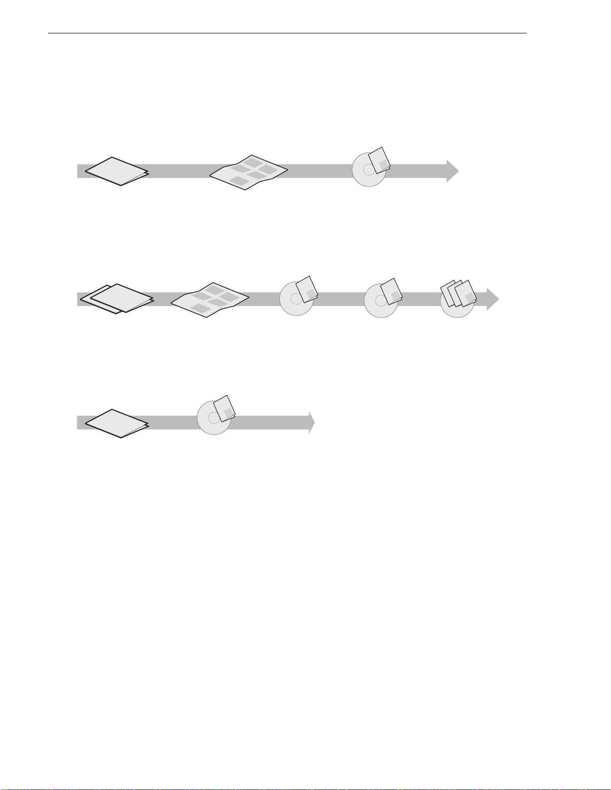
Getting more information
The following illustration shows the recommended order in which to reference the
documentation.
Path for the installer of K2 Media Client models with stand-alone storage
t
r
ta
nt
S
FFFFF FFFFFF FFFFF
FFFFFF FF FF FFFFFF
FFFFFF FF FF FFFFFF
FFFFFF FF FF FFFFFF
FFFFFF FF FF FFFFFF
FFFFFF FF FF FFFFFF
FFFFFF FF FF FFFFFF
K2 Media Client
Release Notes
The latest information about the
hardware and software shipped
with the system. Packaged with
K2 Media Client.
k
ume
c
Qui
is doc
you
K2
Th
ps
you
el
h
ps
you
el
h
ps
el
h
Quick Start Guide
The essential steps for installing
the K2 Media Client. Different
models each have their own
version, packaged with the K2
Media Client.
Grass Valley
K2 Manual
Documentation
CD
K2 Media Client
System Guide*
Specifications and
instructions for
system settings.
Path for the installer of the K2 Storage System with connected K2 Media Clients
ley
Val
FFFFF FFFFFF FFFFF
FFFFFF FF FF F
FFFFFF FF FF FFFFFF
FFFFFF FF FF FFFFFF
FFFFF
FFFFFF FF FF F
Grass
K2 Manual
FFFFF
FFFF FFFFF
FFFFF
FF
FFFFF
FFFFF
FFFFF
FFFFF
FFFFFF FF FF F
FFFFF
FFFFF
FFFFFF FF FF F
FFFFF
FFFFFF FF FF F
FFFFF
FFFFFF FF FF F
FFFFFF FF FF F
FFF FF FF F
FFFFFF FF FF F
FFF
FFFFFF FF FF F
rt
t
a
t
n
e
S
k
c
Qui
u
docum
is
u
K2
Th
ps yo
yo
u
hel
ps
hel
ps yo
hel
Documentation
CD
ley
Grass Val
K2 Manual
Documentation
CD
K2 Media Client and
K2 Storage System**
Release Notes
The latest information
about the hardware and
software shipped with
the system.
Path for the operator
FFFFFF FFFFF
FFFFF
FFFFFF FF FF FFFFFF
FFFFFF FF FF FFFFFF
FFFFFF FF FF FFFFFF
FFFFFF FF FF FFFFFF
FFFFFF FF FF FFFFFF
FFFFFF FF FF FFFFFF
K2 Media Client
Release Notes
The latest information
about the hardware and
software shipped with
the system.
K2 Storage System
Cabling Guide**
Diagrams for
cabling K2 Storage
System devices.
Grass Valley
K2 Manual
Documentation
CD
K2 Media Client
User Manual*
Information for using the user
interface to record, play and
manage clips and to configure
channels.
K2 Storage System
Instruction Manual*
Instructions to
install/configure K2
Storage (SAN), with
K2 Media Client, K2
Media Server.
Find the K2 Documentation CD packaged with K2 Media
*
Clients and with K2 RAID Storage devices, primary chassis.
Find the Storage Release Notes and Cabling Guide
**
packaged with K2 RAID Storage devices, primary chassis.
K2 Media Client
System Guide*
Specifications and
instructions for
system settings.
Other Manuals*
Including:
Quick Start Guide
-
-
User Manual
- Service Manual
- RAID manuals
Quick Start Guide
You receive this guide in the product packaging with your K2 Media Client. The
Quick Start Guide provides step-by-step installation instructions for basic installation
and operation of your K2 Media Client, including recording and playing clips.
ley
Grass Val
Grass Valley
Grass Valley
K2 Manual
K2 Manual
K2 Manual
Documentation
CD
Release Notes
The release notes contain the latest information about the K2 software shipped on
your system. The information in this document includes software upgrade
instructions, software specifications and requirements, feature changes from the
previous releases, and any known problems. Because rele ase n ote s con ta in t he latest
information, they are printed out rather than included in the Documentation
CD-ROM.
24 K2 Media Client Service Manual June 25, 2009
Page 25

K2 Documentation CD
Except for the release notes, the full set of support documentation, including this
manual, is availabl e on the Documentati on CD-ROM that you rece ived with your K2
Media Client.
The K2 Documentation CD includes the following documents:
•
K2 Storage System Instruction Manual — Contains installation, configuration, and
maintenance procedures for shared storage options.
•
K2 Storage System Cabling Guide — Contains diagrams for cabling th e devi ce s of
the K2 Storage System.
•
RAID Instruction Manuals — There is an Instruc tion Manual for each typ e of RAI D
storage device that can be a part of a K2 Media Client. These manuals contain
procedures for configuring and servicing the device.
•
K2 Media Client System Guide — Contains the product specifications and
step-by-step instructions for modifying system settings. Includes instru ctions for
adding a K2 Media Client to the K2 Storage System.
•
K2 Media Client Quick Start Guides — The Quick Start Gui des provides step-by-ste p
installation inst ructions for basic installation and oper ation of the K2 Media Clien t,
including recording and playing clips.
•
K2 Media Client User Manual — Describes the K2 Media Client and provides
instructions for configuring and operating the product.
•
K2 Media Client Service Manual — Contains information on servicing and
maintenance.
NetCentral documentation
The NetCentral product has its own documentation set, described as follows:
•
NetCentral User Guide — This is a printed manual. It provides instructions for
installing, using, and administering the NetCentral monitoring system.
•
NetCentral Help — From the N etCentral interface access on-line help as follows:
• For general help with Ne tCentr al ma nager, select
This content is identica l to that in the NetCentral User Guide.
• For help specific to monitoring K2 Media Client system devices, select
Device Providers
and then select the monitored device.
Thomson Grass Valley Web Site
This public Web site contains all the latest manuals and documentation, and
additional support information. Use the following URL.
http://www.thomsongrassvalley.com.
Help | NetCentral Help Topics.
Help |
June 25, 2009 K2 Media Client Service Manual 25
Page 26

Finding Information
Grass Valley Product Support
For technical assi stance, to check on the status of a qu estion, or t o report ne w issue, cont act
Grass Valley Product Support via e-mail, the Web, or by phone or fax.
Web Technical Support
To access support infor mation on the Web, v isit the pr oduct support Web page on the
Grass Valley Web site. You can download software or find solutions to problems.
World Wide Web: http://www.grassvalley.com/support/
Technical Support E-mail Address: gvgtechsupport@grassvalley.com.
Telephone Support
Use the following information to contact Product Support by phone.
International Support Centers
Our international support centers are available 24 hours a day, 7 days a week.
Support Center Toll free In country
France +800 80 80 20 20 +33 1 48 25 20 20
United States +1 800 547 8949 +1 530 478 4148
Authorized Local Support Representative
A local support represen ta ti ve ma y be avai l abl e in your count ry. To locate a support
ce
ter during normal local business hours, refer t o the following list. Th is list is
n
regularly updated on the website for Thomson Grass Valley Product Support
(http://www.grassvalley.com/support/contact/phone/).
After–hours local phone support is also available for warranty and contract
omers.
cust
Region Country Telephone
Asia
Pacific
Central America,
South America
North America
China +86 10 5883 7575
Hong Kong, Taiwan, Korea, Macau +852 2531 3058
Japan +81 3 6848 5561
Southeast Asia - Malaysia +603 7492 3303
Southeast Asia - Singapore +65 6379 1769
Indian Subcontinent +91 11 515 282 502
Australia, New Zealand +61 1300 721 495
All +55 11 5509 3440
North America, Mex ico, Caribbean +1 800 547 8949
+91 11 515 282 504
+1 530 478 4148
26 K2 Media Client Service Manual June 25, 2009
Page 27

Telephone Support
Region Country Telephone
Europe
UK, Ireland, Israel +44 118 923 0499
Benelux – Netherlands +31 (0) 35 62 38 421
Benelux – Belgium +32 (0) 2 334 90 30
France +800 80 80 20 20
+33 1 48 25 20 20
Germany, Austria, Eastern Europe +49 6150 104 444
Middle East,
Near East, Africa
Belarus, Russia, Tadzhikistan
Ukraine, Uzbekistan +7 095 258 09 20
,
+33 (0) 2 334 90 30
Nordics (Norway, Sweden, Finland, Denmark, Iceland) +45 40 47 22 37
Southern Europe – Italy +39 02 24 13 16 01
+39 06 87 20 35 42
Southern Europe – Spain +34 91 512 03 50
Middle East +971 4 299 64 40
Near East and Africa +800 80 80 20 20
+33 1 48 25 20 20
June 25, 2009 K2 Media Client Service Manual 27
Page 28

Finding Information
28 K2 Media Client Service Manual June 25, 2009
Page 29

Chapter 1
Product Description
Topics in this section in clude the following:
•“Overview description” on page 30
•“K2 Media Client orientation” on page 30
•“FRU functional descriptions” on page 34
•“Status indicators” on page 39
June 25, 2009 K2 Media Client Service Manual 29
Page 30

Chapter 1 Product Description
Overview description
The K2 Media Client is a cost-effective media platform that incorporates IT and
storage technologies to deliver a networked solution to facilities for ingest, playout,
and media asset manag ement . I t i s a comprehensive plat for m th at provides a suite o f
user applications , system tools , and the larges t range of thi rd party intera ctivity in the
industry.
Refer to the K2 Medi
features, controls, applications, and subsystems.
a Client System Guide for other high-level descriptions of
K2 Media Client orientation
The following illu strat ions s how the l ocati on of Fi eld Repl aceab le Un its (F RUs) and
other components in the K2 Media Client. For clarity, illustrations of internal
components are shown with the top cover removed and no cabling displayed. Note
that the RTP board and the Dual Ethernet adapter are in different lo cations in differe nt
models. Also, some SAN K2 Media Client have different units that provide disk
backplane functionality.
Front view components
Front panel
DVD drive
RAID drives
Front bezel
Fan module
30 K2 Media Client Service Manual June 25, 2009
Page 31

Rear view components SDA-00 model
Codec board
SCSI interface
board
DVD drive
Center support
RS-422 board*
RS-422 board*
RS-422 configuration varies.*
SCSI controller adapter
configuration varies.
**
Some external storage
K2 Media Clients have a
bracket and two SATA drive
connector boards rather than
a backplane.
XLR board
Power supplies
Motherboard
Rear card guide
Dual Ethernet board
(optional)
SCSI controller adapter**
RTP board
Graphics board
SCSI backplane
Rear view components SDA-00 model
June 25, 2009 K2 Media Client Service Manual 31
Page 32

Chapter 1 Product Description
Codec board
SCSI interface
board
DVD drive
Center support
RS-422 board*
RS-422 board*
XLR board
Power supplies
Motherboard
Rear card guide
Dual Ethernet board
SCSI controller adapter**
RTP board
Graphics board
SCSI backplane
Some external storage
K2 Media Clients have a
bracket and two SATA drive
connector boards rather than
a backplane.
RS-422 configuration varies.
SCSI controller adapter
configuration varies.
**
*
Rear view components SD-00 model
32 K2 Media Client Service Manual June 25, 2009
Page 33

Rear view components HD-00 model
Codec board
Mezzanine boards
(under codec board)
SCSI interface
board
DVD drive
Center support
RS-422 board*
RS-422 board*
XLR board
Power supplies
Motherboard
Rear card guide
RTP board
SCSI controller adapter**
Dual Ethernet board
Graphics board
SCSI backplane
Some external storage
K2 Media Clients have a
bracket and two SATA drive
connector boards rather than
a backplane.
RS-422 configuration varies.
SCSI controller adapter
configuration varies.
**
*
Rear view components HD-00 model
June 25, 2009 K2 Media Client Service Manual 33
Page 34

Chapter 1 Product Description
FRU functional descriptions
The Field Replaceab le Units (FRUs) described in this section are as follows:
• “Base chassis”
• “F
an module ”
• “RAID drives”
• “Power supplies”
• “Removable media drives”
• “Codec board”
• “Mezzanine boards”
• “RTP board”
• “XLR board”
• “RS-422 adapters”
• “Dual Ethernet adapter”
• “Graphics board”
• “SCSI contr oller adapter”
• “SCSI interface board”
• “SCSI backplane”
• “CPU motherboard”
For procedures, refer to Chapter 5, Removi
Base chassis
For some serious sys tem fault s or for mechani cal damage , the entire K2 Media Clien t
can be replaced as a base chassis FRU. Refer to “Replacing a K2 Media Client” on
page 92.
Fan module
The fan module has three fa ns and pr ovides cooli ng for t he K2 Media Client cha ssis.
Air intake is from the front of the K2 Media Client and outflow is through the rear.
The fan module is accessed behind the front bezel.
Refer to “Fan module removal” on page 117 for procedures.
RAID drives
ng and
replacing FRUs.
There are 12 slots for RAID drives in the K2 Media Client. They are located behind
the fan module in the front of the unit. Internal storage model s have two RAID drives
for system data and five or ten RAID drives for medi a storage. Ext ernal sto rage units
have only the two RAID drives for system data.
34 K2 Media Client Service Manual June 25, 2009
Page 35

The two RAID 1 drives for system dat a form one LUN and the RAID drives for medi a
storage are configured as RAID 1 or RAID 0. Each LUN appears to the operating
system as a single disk .
In internal storage models, media data is written or “striped” across the media disks
in a
continuous fashion, which makes the disks a “stripe group”. This media stripe
group appears as the V: drive to the Windows operating system.
The system disk has a C: partition for application and operating system files, a D:
part
ition for the med ia file syst em, database, and configuration information, and an E:
partition for recovery images.
When configured as RAID 1, yo u can remove and replace a RAI D drive while t he K2
Med
ia Client is operational. Re fer to “RAID disk removal” on page 119 for
procedures.
Power supplies
The K2 Media Client has red undant (two) po wer supplies. The power suppli es can be
accessed from the re ar of the un it. You can re move and re place a power supply while
the K2 Media Client is oper ational. Each power suppl y has a fan with automatic speed
control and statu s LEDs that i ndicate curre nt state and health. Refer to “Power supply
problems” on page 103 for LED descriptions. The power supply has protection for
over voltage, over current, and short circuits.
Power supplies
Refer to “Power supply removal” on page 119 for procedures.
Removable media drives
The K2 Media Client uses a standard remova ble media drive similar to those fo und in
desktop PCs. The drive is accessed behind the front bezel. The drive uses standard
Windows drivers for e asy plug-and- play insta llation. K2 Media Client options for the
removable media drive is as follows:
• One standard CD drive.
Refer to “Removable media drive removal” on page 123 for procedures.
Codec board
The codec board is ori ented horizontally across the rear of the K2 M edia Client
chassis. It provides the majority of the K2 Media Client’s media-related input and
output connectors on the rear panel. This board hosts the circuits responsible for
encoding/decoding video and processing audio and timecode. It is connected to the
motherboard via the RTP board.
The SDA-00 model, the SD-00 model, and the HD-00 model each use a different
board. The codec board in the HD-00 model can also host the mezzanine
codec
boards, as described below.
Refer to “Codec board removal” on page 124 for procedures.
June 25, 2009 K2 Media Client Service Manual 35
Page 36

Chapter 1 Product Description
Mezzanine boards
There are two types of mez zanine boards : an encoder mezzanine board a nd a decoder
mezzanine board. Th e codec board i n the HD-00 K2 Medi a Client can hos t one or two
mezzanine boards of either type, so the number and typ e of mezzanine boa rd s on the
codec board determines the fixed channel configuration of the HD-00 K2 Media
Client model. The encoder mezzanine board provides one record channel, while the
decoder mezzanine board provides one play channel.
Refer to “Codec board removal” on page 124 for procedures.
RTP board
This Real Time Processor (RTP) board pr ovi des a dedic ate d rea l ti me proc ess or and
connections for medi a access an d processing . It functi ons as a rise r board, conn ecting
to the PCI slot below and the Codec board above.
Refer to “RTP board removal” on page 127 for procedures.
XLR board
The XLR Board provides XLR connectors at the K2 Media Client rear panel. It is
primarily an exten sion o f the codec bo ard t o all ow the space an d orient ation re quire d
for XLR connections. On the SDA-00 model, the XLR connections are used for
analog audio and LTC. On other models, t he XLR connections are only used for LTC.
The XLR board is connected via cable to the codec board.
Refer to “XLR board removal” on page 138 for procedures.
RS-422 adapters
RS-422 configuration varies, as follows:
• A K2 Media Client wit h a Type I II mother board has RS-422 ada pters i n rear panel
sl
ots 1 and 7. A K2 Media Client with a Type I mot her board has RS-422 adapters
in rear panel slots 3 and 7. Each a dapter is connected via an intern al USB ca ble to
the motherboard, so while a RS-422 adapter does occupy a rear panel slot, it does
not plug into a PCI bus. Each adapter provides two RS-422 ports for connecting
equipment for remote control of the K2 Media Client.
• A K2 Media Client with a Type II motherboard has one RS-422 adapter. The
adapter is connected via PCI slot to the motherboard. T he adapter includes an
external interface with eight ports. On the external interface, ports 1–4 are active.
This provides the four ports for connecting equipmen t for remote control of the K2
Media Client.
Refer to “RS-422 adapter removal” on page 133 for procedures.
Dual Ethernet adapter
The dual Ethernet adapter provides two Gigabit Ethernet ports. The dual Ethernet
adapter plugs into one of the standard P CI slots on the motherboar d. On some models
the dual Ethernet adapter is optional.
Refer to “Dual Ethernet adapter removal” on page 136 for procedures.
36 K2 Media Client Service Manual June 25, 2009
Page 37

Graphics board
This board provides enhanced performance for screen graphics and a connection for
a VGA monitor. The graphics board plugs into one of the standard PCI slots on the
motherboard.
Refer to “Graphics board removal” on page 135 for procedures.
SCSI controller adapter
A K2 Media Client must provide RAID cont roller functional ity for the interna l RAID
disks. On internal storage models, both system and media da ta require this RAID
controller functionality, as both are stored on the internal RAID disks. On external
storage models, only the system data requires RAID controller functionality, as the
media is stored on the K2 Storage System or on direct-connect RAID storage.
Therefore, RAID cont roller adapter configuration varies, as fol lows:
• Some external st orage K2 Media Clients h ave no RAID controller adapter. Instead,
e RAID controller functi onality is provid ed by the motherboard. Also, t hes e K2
th
Media Clients have SATA drive connector boards rather than a SCSI backplane.
• Other K2 Media Clients have a SCSI controller adapter and a SCSI backplane.
These K2 Media Clie nt can be eit her i ntern al stor age or exte rnal st orage . On th ese
K2 Media Clients the SCSI controller adapter provides the SCSI controller
functionality for the internal RAID disks. The SCSI controller adapter plugs into
one of the standard PCI slots on the motherboard.
Graphics board
Refer to “SCSI controller adapter removal” on page 137 for procedures.
SATA drive connector board
A K2 Media Client must provide connections for RAID drives to support hot-swap
functionality. On internal storage models, both system and media drives require
connections. On external storage models, only the two system drives require
connections. Therefore, backplane configuration varies, as follows:
• Some external storage K2 Media Client have no SCSI backplane. Instead, RAID
e connections are pro vided by two SATA dri ve connector boards , supported by
driv
a bracket, which is mounted in the center of the unit. On these K2 Media Clients
there is also no SCSI co ntroller adapter.
• Other K2 Media Clients have a SCSI backplane and a SCSI controller adapter.
These K2 Media Client can be either internal storage or external storage.
Refer to “SATA drive connector board removal” on page 131 for procedures.
SCSI interface board
This board provides the SCSI interface for the RAID drives. It monitors and reports
the status of the RAID drives , the chassis fans, and the power suppli es. It also controls
the individual RAID status LEDs and the front panel Power and Service LEDs. It is
mounted horizontally in the front of the unit, above the RAID drives. It provides a
front panel USB connection.
Refer to “SCSI interface board removal” on page 122 for procedures.
June 25, 2009 K2 Media Client Service Manual 37
Page 38

Chapter 1 Product Description
SCSI backplane
A K2 Media Client must provide connections for RAID drives to support hot-swap
functionality. On internal storage models, both system and media drives require
connections. On external storage models, only the two system drives require
connections. Therefore, backplane configuration varies, as follows:
• Some external storage K2 Media Client have no SCSI backplane. Instead, RAID
e connections are provided by two SATA drive connector boards.
driv
• Other K2 Media Clients have a SCSI backplane and a SCSI controller adapter.
These K2 Media Client can be either internal storage or external storage. On these
K2 Media Clients the SCSI backplane provides the connection for each RAID
drive. It is mounted in the center of the unit.
Refer to “SCSI backplane removal” on page 129 for procedures.
CPU motherboard
The K2 Media Client uses an extended ATX motherboard with an Intel Xeon
processor. The motherboard provides PCI board slots, built in Gigabit Ethernet, and
USB ports. The Type I motherboard provides USB 1.1 ports. The Type II and Type
III motherboard provides USB 2.0 ports. It is located in the bottom rear of the K2
Media Client chassis.
Refer to “CPU motherboard replacement” on page 140 for procedures.
38 K2 Media Client Service Manual June 25, 2009
Page 39

Status indicators
!
The following sections describe the visual and audible indicators that communicate
the current operating status and system health of the K2 Media Client.
Front panel indicators
You can see the front panel LEDs while the front bezel is closed or open.
Bezel Release
Buttons
Status indicators
Power LED
This LED indicates st atus as follows:
Off: The standby switch is set to Off and the K2 Media Client is not operational.
Steady on (green): The
in the startup process or has competed the startup process and is operational.
Power
LED
WARNING: The
tem. To turn power off the system must be disconnecte d from the
sys
power standby switch does not turn off power to the
Service
LED
!
power source.
standby switch is set to On an d the K2 Medi a Client is ei ther
Service LED
The following table explains the status conditions indicated by the different Service
LED be
haviors. If two or more status conditions occur simultaneously, the LED
displays the behavior for the highest priority condition.
LED behavi or Status Condition Priority
Flashing pattern alternating
Yellow/Green/Red/Off twice a
second
Identify — The K2 Media Client is being directed to
entify itself by NetCentral or some other
id
application.
1
June 25, 2009 K2 Media Client Service Manual 39
Page 40

Chapter 1 Product Description
LED behavior Status Condition Priority
Solid Red Global failure — The K2 Media Cli ent system
2
software has detected a critical error or failure that
impacts record/play operations.
Solid Yellow Warning — The K2 Media Client system software has
Flashing Yellow pattern three time
a second
Flashing pattern alternating
Yellow/Green once a second.
Off Normal — The K2 Media Client is healthy and
.
RAID drive indicators
On a K2 Media Client with a SCSI backplane, each RAID drive has LEDs that
indi
cate status. You must remove the fan module to see these LEDs. The following
table explains the status conditions indicated by the different LED behaviors. If two
or more status condition s occur simultaneously, the LED displays the behavior for the
highest priority condition.
LED behavi or Status Condition Priority
Flashing pattern alternating
Yellow/Green/Red/Off twice a
second
Both Red and Green LED off Drive is not fully engaged in slot. 2
de
tected a problem that requires attentio n but does n ot
immediately impact record/play operations. For
example, a fan or power supply has failed but its
redundant partner is maintaining functionality.
Drive failure — An internal RAID drive has failed. If
RAID 1, the failure does not immediately impact
record/play operations. The redu ndant partner RAID
drive is maintaining functionality.
Drive rebuild — If RAID 1, an internal RAID drive is
rebuilding.
erating normally.
op
Identify — The RAID drive is being directed to
entify itself by Storage Utility or some other
id
application.
3
4
5
5
1
Red LED is ON solid. Green LED
is off.
Flashing pattern alternating
ow/Green once a second
Yell
Red LED is off. Green LE D
displ
ays pulsing patterns.
ault — The SCSI controller has marked the drive as
F
faulty.
Rebuild — The SCSI controller has marke d the drive
as rebuilding.
Normal drive activity — The RAID drive is healthy
and disk access is underway. (Both LEDs are off when
there is no disk activity.)
3
4
5
On a K2 Media Client without a SCSI backplane, ref er to “Using th e Adaptec Storage
Manager to identify a failed drive” on page 54.
Rear panel indicators
The following indicators are visible from the rear panel view.
40 K2 Media Client Service Manual June 25, 2009
Page 41

Motherboard LAN connector indicator codes
Yellow LED
Green/Orange LED
The motherboard has two RJ-45 LAN connect ors that include integrated st atus LEDs.
Th
e LEDs are oriented as follows:
The meanings of the LED states are described in the following table:
LED LED state Condition
Green/Orange Green On 100 MHz.
Orange On 1 GHz
Yellow Off LAN link is not established
On (steady state) LAN link is established
On (brighter and pul s ing) The computer is communicating with another
c
omputer on the LAN.
Rear panel indicators
If a LAN connector is faulty, you must replace the motherboard.
Dual Ethernet adapter LAN connector indicator codes
The dual Ethernet adapter has two RJ-45 LAN connectors that include integrated
atus LEDs. The LEDs are oriented as follows:
st
Green/Orange LED
Green LED
The meanings of the LED states are described in the following table:
LED LED state Condition
Green/Orange Green On 100 MHz.
Orange On 1 GHz
Green Off LAN link is not established
On (steady state) LAN link is established
On (brighter and pul s ing) The computer is communicating with another
c
omputer on the LAN.
If a LAN connector is faulty, you must replace the dual Ethernet adapter.
June 25, 2009 K2 Media Client Service Manual 41
Page 42

Chapter 1 Product Description
Power supply indicators
Each power supply has a LED that indicates status.
Interpret the power supply LED as follows:
LED behavi or Power supply condition
Green ON No rmal operation
OFF Power supply is defective or not fully connected.
Status LEDs
The Service LED on the front of the K2 Media Client also indicate s power supply
st
tus. Refer to “Service LED” on page 39.
a
If the power source and the power cord are OK and the status lights on the power
suppl
y indicate a problem, replace the power supply. Refer to “Power supply
removal” on page 119.
System beep codes
If there are no errors present the K2 Media Client does not emit any audible beeps
during startup process or otherwise. When a recoverable type of error occurs during
Power On Self Test (POST), the motherboard BIOS will display a POST code that
describes the problem. Ref er to “BIOS POST mess ages” o n page 44. Th e BIOS may
also issue one of the following beep codes:
Error Beep Code Description
One long and two short beeps Video configur a tio n err o r
One continuous long beep No memory detected
These beep codes indicate a problem with the motherboard.
42 K2 Media Client Service Manual June 25, 2009
Page 43

Chapter 2
System Messages
Topics in this section in clude the following:
• “About system messages” on page 44
• “BIOS POST messages” on page 44
• “Critical system startup messages” on page 48
• “Viewing A ppCenter system stat us messages” on page 48
June 25, 2009 K2 Media Client Service Manual 43
Page 44

Chapter 2 System Messages
About system me ss a ges
The following messages are displayed to indicate K2 Media Client status:
• Normal BIOS messages — During norma l startup processes thes e messages can be
obser
ved on a locally connected VGA monitor. Refer to “Motherboard BIOS
startup information” on page 97, “RAID controller BIOS startup information” on
page 98, and “Motherboard BIOS startup summary screen” on page 99.
• BIOS POST error messages — If there i s a problem these messages are displayed
on a locally connected VGA monitor startup processes. Refer to “BIOS POST
messages” on page 44.
• K2 Media Client startup messages — As AppCenter opens the K2 Media Client
determines if system hea lt h is adequate by checking criti ca l sub sys te ms. A dial og
box is displayed that indicates progress and displays messages. Refer to “Critical
system startup messages” on page 48.
• Status bar and StatusPane messages — During normal operation AppCenter
displays system status mess ages on the status bar. From the stat us bar you can open
the StatusPane to see both current and previous messages. You can observe these
messages in AppCenter on a locally connected VGA monitor or on a network
connected control point PC. Refer to “Viewing AppCenter system status
messages” on page 48.
• Storage Utility mess age s — Whil e y ou are using Storage Ut il it y, p op-up message
boxes inform you of the current status of the storage system.
• NetCentral messages — If you are monitoring the K2 Media Client with
NetCentral, the NetCent ral interface displa ys a variety of messages an d other status
indicators. Refer to the NetCentral H elp menu for a complete lis t of all the
messages that a monitored device can send.
BIOS POST messages
During the Power On Self Test (POST), the motherboard BIOS checks for problems.
If a problem is found, the BIOS activ ate s an alar m or dis plays a messag e. For s tart up
troubleshooting ref er to “Step 4: Identify problems using the startup sequence” on
page 94.
The following is a list of BIOS POST messages.
BIOS Message Description
Failure Fixed Disk Fixed disk is not working or not configur ed
Stuck key Stuck key on keyboard.
properly. Check to see if fixed disk is attached
properly. Run Setup. Fin d out if the fixed-disk type
is correctly identified.
Keyboard error Keyboard not work ing.
Keyboard Controller Failed Keyboard controller failed test. May require
re
placing keyboar d controller.
44 K2 Media Client Service Manual June 25, 2009
Page 45

BIOS POST messages
BIOS Message Description
Keyboard locked - Unlock key switch Unlock the system to proceed.
Monitor type does not match CMOS -
Run SETUP
Shadow Ram Failed at offset: nnnn Shadow R A M failed at offset nnnn of the 64k
System RAM Failed at offs e t: nn nn System RAM failed at offset nnnn of in the 64k
Extended RAM Failed at offset: nnnn Extended memory not working or not configured
Monitor type not correctly identified in Setup
block at which the error was detected.
bl
k at which the error was detected.
oc
erly at offset nnnn.
prop
System battery is dead - Replace and
run SETUP
System CMOS checksum bad De
fault configuration used
System timer error The timer test failed. Requires repair of system
Real time clock error Real-Time Clock fails BIOS hardware test. May
Check date and time settings BIOS found date or time out of range and reset the
Previous boot incomplete - Default
confi
guration used
The CMOS clock battery indicator shows the
battery is dead. Replace the batter y and run Setup
to reconfigure the system.
System CMOS has been corrupted or modified
incorrectly, perhaps by an application program
that changes data stored in CMOS. The BIOS
installed Default Setup Valu es. If y ou do no t wan t
these values, enter Setup and enter your own
values. If the error persists, check the system
battery or contac t your dealer.
r
d.
boa
require bo ard repair.
R
al-Time Clock. May require setting legal date
e
(1991-2099).
Previous POST did not complete successfully.
POST loads default values and offer s to run Setup.
If the failure was caused by incorrect values an d
they are not corrected, the next boot will likely fail.
On systems with control of wait states, improper
Setup settings can also terminate POST and cause
this error on the next boot. Run Setup and verify
that the waitstate configuration is correct. This
error is cleared the next time the system is booted.
Memory Size f ound b y POST dif fered
from CMOS
Diskette drive A error Drive A: or B: is present but fails the BIOS POST
Diskette drive B error
Incorrect Drive A type - run SETUP Type of floppy drive A: not correctly identified in
Incorrect Drive B type - run SETUP Type of floppy drive B: not correctly identified in
emory size found by POST differed from
M
CMOS.
ette tests. Check to see that the drive is defined
disk
with the proper diskette ty pe in S et up and t ha t th e
diskette drive is attached correctly.
tup.
Se
up.
Set
June 25, 2009 K2 Media Client Service Manual 45
Page 46

Chapter 2 System Messages
BIOS Message Description
System cache error - Cache disabled RAM cache failed and BIOS disabled the cache.
CPU ID: CPU socket number for Multi-Processor error.
EISA CMOS not writeable ServerBIOS2 test error: Cannot write to EISA
DMA Test Failed ServerBIOS2 test error: Cannot write to extended
Software NMI Failed ServerBIOS2 test error: Cannot generate software
Fail-Safe Timer NMI Failed ServerBIOS2 test error: Fail-Safe Timer takes too
device Address Conflict Address conf lict for specifie d de vice.
Allocation Error for: device Run ISA or EISA Con figu ra tio n Utilit y to resolve
On older boards, check the cache jumpers. You
may have to replace the cache. See your dealer. A
disabled cache slows system performance
considerably.
CM
S.
O
DMA (Di
NMI (No
long.
r
esource conflict for the specified device.
ect Memory Access) registers.
r
n-Maskable Interrupt).
CD ROM Drive CD ROM Drive identified.
Entering SETUP… Starting Se tup pr og ram
Failing Bits: nnnn The hex number nnnn is a map of the bits at the
R
AM address which failed the memory test. Each
1 (one) in the map indicates a failed bit. See errors
230, 231, or 232 abov e for offset address of the
failure in System, Extended, or Shadow memory.
Fixed Disk n Fixed disk n (0-3) identified.
Invalid System Configuration Data Problem with NVRAM (CMOS) data.
I/O device IRQ conflict I/O device IRQ conflict error.
PS/2 Mouse Boot Summary Screen: PS/2 Mouse installed.
nnnn kB Extended RAM Passed Where nnnn is the a mount of RAM in kilobytes
successfu
nnnn Cache SRAM Passed Where nnnn is the amount of sys tem cache in
kilo
nnnn kB Shadow RAM Passed Where nnnn is the am ount of shadow RAM in
k
ilo
nnnn kB System RAM Passed Where nnnn is the am ount of system RAM in
kilo
One or more I2O Block Storage
Devices were excluded from the Setup
Boot Menu
There was not enough room in the IPL table to
display all insta lled I2O blockstorage devices.
lly tested.
bytes successfully tested.
bytes successfully tested.
bytes successfully tested.
Operating system not found Operating system cannot be located on either drive
A:
or drive C:. Enter Setup and see if fixed disk
and drive A: are properly identified.
46 K2 Media Client Service Manual June 25, 2009
Page 47

BIOS POST messages
BIOS Message Description
Parity Check 1 nnnn Parity error found in the system bus. BIOS
attempts to locate the address and display it on the
screen. If it cannot locate the address, it displays
????. Parity is a method for checking errors in
binary data. A parity error in dicates that some data
has been corrupted.
Parity Check 2 nnnn Parity error found in the I/O bu s. BIOS attempts to
locate the address and display it on the screen. If it
cannot locate the address, it displays ????.
Press <F1> to resume, <F2> to Setup,
<F3>
for previous
Press <F2> to enter Setup Optional message displaye d during POST. Ca n be
PS/2 Mouse: PS/2 mouse identified.
Run the I2O Configuration Utility One or more unclaimed block storage devices have
System BIOS shadowed System BIOS copied to shadow RAM.
UMB upper limit segment address:
nnnn
Video BIOS shadowed Video BIOS successfully copied to shadow RAM.
Displayed after any recoverable error message.
Press <F1> to start th e boot process or <F2> to
enter Setup and change the se ttings. Press <F3 > to
display the previous screen (usually an
initialization error of an Option ROM, i.e., an
add-on card). Write down and follow the
information shown o n the screen.
u
rned off in Setup.
t
the Configuration Request b it set in the LCT. Run
an I2O Configuration Utility (e.g. the SAC ut ility).
plays the address nnnn of the upper limit of
Dis
Upper Memory Blocks, indicating released
segments of the BIOS which can be reclaimed by
a virtual memory manager.
June 25, 2009 K2 Media Client Service Manual 47
Page 48

Chapter 2 System Messages
Critical system startup messages
The following messages appear in the AppCenter system startup message box as
critical subsystems are checked during K2 Media Client startup processes. If one of
these critical subsystems fails, the K2 Media Client is rendered inoperable and the
failure me ssage appears.
Critical subsystem check messages Failure messages
System Startup Startup error
Checking hardware… Hardware fault
Checking media disks… One or more media disks failed to initialize
Checking file system… No file system is running
Checking database… Database fault
Missing or bad hardware
The real time processor is not functioning correctly
Missing or bad hardware
Missing or bad SQL database
Checking real-time system status… The real-time system failed to initialize
Updating configuratio n… Failed to synchronize configurations
Starting services… Unable to communicate with <service name>
Viewing AppCenter system status messages
System status mess ages are di splayed in the AppCenter status ba r. There ar e two type
of system status messages, as follows:
• Channel status messages — In normal operati on, th is type of messa ge displ ays th e
cu
rrent operating status of the selected channel.
• System error messages — If a problem develops with the system software or a
hardware subsystem, this type of message is displayed for approximately 5
seconds. Afterward, the display returns to the channel status message and the error
message is written to t he status log file. Whe n a message is written to the status log,
a Status Icon indicates the severity of the message.
48 K2 Media Client Service Manual June 25, 2009
Page 49

Viewing system status messages
Status Messages
Protocol
Monitor
Button
Transfer
Monitor
Button
StatusPane
Button
Player 2: Playing 'List_10', 'Section 1', 'Clip_2'
System status messages appear in the AppCenter status bar, which is located across
the bottom of the AppCenter window, and consists of a message area, several tool
buttons, and a status icon. The button icons appear only when the related function is
active. In the position of the StatusPane button, status icons appear.
The status icon changes depending on the status of the current status message.
Icon Name Description
Information A recent information message is pre sent.
Viewing system status messages
Warning There is at least one warning message, and no alert messages.
Alert There is at least one uncleared alert message.
Current and previous system status messages can be viewed in the StatusPane. To
he StatusPane, click
open t
Help | System Status.
June 25, 2009 K2 Media Client Service Manual 49
Page 50

Chapter 2 System Messages
Status icon
Date Time The machine that
reports this message
The subsystem that
reports this message
The StatusPane is used to view detailed system messages including status, warning,
and error messages. System stat us messages provid e status i cons and a d escri ption of
the status event reported by the message. If there is a problem, a corrective action is
indicated. Use these messages along with Chapter 4, Troubleshooting problems to
termine if a service procedure is necessary.
de
If you have a remote AppCenter Channel Suite with channels from multiple K2 Media
Clie
nts, the messages from the different machines are combine d in the StatusP ane that
you view from the Cha nnel Suite. To help you determine which machin e is generating
a message, each message lists the machine name.
Copying StatusPane messages to the clip board
1. Select the message or messages in the StatusPane.
2. Click
Copy.
After copying the message, it can be pasted using standard Windows techniques.
Clearing messages
Clearing messages from the St atusPane removes them from t he loggin g databas e and
the StatusPane. This also clears the state of the subsystem i ndicators so they no longer
display the alert and warning symbols.
1. Open the StatusPane, then click
Clear.
2. When a message prompts you to confirm, click
Yes.
All messages are removed from the StatusPane and logging database.
50 K2 Media Client Service Manual June 25, 2009
Page 51

Chapter 3
Service Procedures
Topics in this section in clude the following:
•“Exporting log files” on page 51
•“Re
placing a RAID 0 drive” on page 53
•“Replacing a RAID 1 drive” on page 53
•“Using the Adaptec Storage Manager to identify a failed drive” on page 54
•“Configuring Event Viewer” on page 68
•“Checking services” on page 69
•“Checking pre-installed software” on page 72
•“Configuring NVRAM” on page 73
•“Making motherboard CMOS settings” on page 76
•“Rescanning PCI slots” on page 79
•“Using recovery disk images” on page 79
•“Installing the Fibre Channel card driver” on page 90
•“Replacing a K2 Media Client” on page 92
Exporting log files
The procedures in this section describe how to export log files from the K2 Media
Client. The log files can include the following:
• All applications messages
• The
Windows Event Log
• Logs from the media database.
• Dr. Watson messages.
The exported log files are combined in a ZIP file. The ZIP file can be sent to Grass
Val
l
ey product support where the y can analyze the logs to d et ermi ne t he operational
status of your K2 Media Client.
NOTE: ExportLog does not export StatusPane messages. To capture StatusPane
ssages, refer to the “Copying StatusPane messages to the cli p board” on page 50.
me
Use one of the following procedures to export the logs.
Exporting log files from AppCenter workstation
1. In AppCenter workstation click
opens.
2. Click the
June 25, 2009 K2 Media Client Service Manual 51
Logs tab.
System | Export Log. The Export Log dialog box
Page 52

Chapter 3 Service Procedures
3. Select the logs to export.
4. Click the
Destination tab.
5. Browse to a location for saving the log file.
6. Name the log file.
7. Click
8. When the export process is complete, and message confirms success. Click
Export. A progress bar appears.
OK and
close the Export Log dialog box to continue.
9. Find the log file at the specified location.
52 K2 Media Client Service Manual June 25, 2009
Page 53

Exporting log files using the Windows command line
This procedure allows you to export log files even if AppCenter does not start
prope
rly. It uses the Windows command prompt.
1. If you have not already done so, connect a mouse and keyboard to the K2 client
sys
tem.
Replacing a RAID 0 drive
2. In the Windows task bar, select
3. Type the following in the Run dialog box, then click
c:\profile\exportlog
The ExportLog dialog box is displayed.
4. Continue with the proced ure “Exporting lo g files from AppCent er workstation” on
page 51, starting with step 2.
Start | Run.
Replacing a RAID 0 drive
If configured as RAID 0 (internal sto rage media drive s only), when one dr ive fails, all
media is lost. To replace a RAID 0 drive, do the following:
1. Unbind the LUN that has the failed drive. Do not unbind the system drive RAID 1
LUN.
2. Remove the failed drive from the K2 Medi a Client chassis.
3. Insert the replacement drive in the K2 Media Client chassis.
4. Restart the K2 Media Client.
5. Using Storage Utility on the K2 Media Client, bind disks as RAID 0.
6. Restart the K2 Media Client.
7. Using Storage Utility on the K2 Media Client, make a new file system.
OK.
8. Restart the K2 Media Client.
Always use the Storage Utility to physically identify the failed drive. Accidently
r
e
moving the wrong drive can destroy data. To identify a drive, in Storage Utility
right-click the drive and select
Refer to the K2 Medi
Refer to “RAID disk removal” on page 119 for the mechanical procedure for
removing and inserting a drive.
a Client System Guide for Storage Utility procedures.
Identify. This causes the disk lights to flash.
Replacing a RAID 1 drive
If configured as RAID 1, you’ll repair the system by replacing the drive as soon as
possible. The two RAID drives that make the system drive are always RAID 1. You
can replace a single RAID 1 drive (either system or media) while continuing media
operations.
June 25, 2009 K2 Media Client Service Manual 53
Page 54

Chapter 3 Service Procedures
For K2 Media Clients with the SCSI controller adapter (LSI board), always use the
Storage Utility to physically ident ify the failed dr ive. Accidently re moving the wrong
drive can destro y data. To i dentify a drive, i n Storage Ut ility rig ht-clic k the d rive and
Identify. This causes the disk l ights to flas h. Refer to the K2 Media Client
select
System Guide for Storage Utility procedures.
For K2 Media Clients without the SCSI controller adapter (LSI board), always open
th
e Adaptec Storage Manager to identify the failed drive. Accidently removing the
wrong drive can destroy data.
Before removing the dis k modul e, you shoul d use Stor age Uti lity to di sab le the di sk.
Refer to “RAID disk removal” on page 119 for the mechanical procedure for
removing and inserting a drive.
On inserting a RAID 1 replacement drive, if disk access (record/play operations) is
under
way, the RAID controller automatically starts rebuilding the drive. You can
verify rebuild status by looking at the drive LED or by looking at the Service LED.
Refer to “Front panel indicators” on page 39. If there is no media access curre ntly
underway, you can use Storage Utility to force-start the rebuild process.
You can also ch eck disk sta tus in the Storage Utili ty by select ing the disk module icon
he device tree. Status is reported in the right-hand pane. On completion, the disk
in t
drive status ch anges fr om Rebuildi ng to Onli ne. You ma y need to refres h the Stor age
Utility display. You can also open the Progress dialog box, by clicking
Report
.
View | Progress
Using the Adaptec Storage Manager to identify a failed drive
This procedure app lies to K2 Media Clie nts witho ut the SCSI controll er adapt er (LSI
board). These K2 Media Clients can be identified by the absence of the SCSI
controller adapter in slot six of the rear panel.
1. From the Windows desktop, click
Adaptec Storage Manager
.
The Adaptec Storage Manager opens.
2. In the tree-view, expand the top node and select the node named for the local K2
Medi
a Cl
ient.
The Log in dialog box opens.
3. Log in with the local K2 Media Client’s administrator username and password. By
de
ult this is as follows:
fa
• Administrator
•ad
minK2
4. If a New hardware detected message box appears, click
5. In the list-view area of the Adaptec Stor age Manager wind ow, click the button that
di
splays the following text:
Controller 1
RAID controller
Start | All Programs | Adaptec Storage Manager |
Register Later.
54 K2 Media Client Service Manual June 25, 2009
Page 55

SATA HostRAID
Controls for Physical devices and Logical devices appear.
6. Expand the control under Physical devices.
Controls for Slot 0 and Slot 1 appear.
7. Identify the slot that displays th e error indi cating the f ailed drive.
You can also select the c ontrol for Sl ot 0 or Slot 1 and vi ew stat us messa ges at th e
bo
tt
om of the Adaptec Storage Manager window.
8. Position yourself facing the front of the K2 Media Client and proceed as follows:
• If Slot 0 is the failed drive, replace the drive on your left.
• I
f Slot 1 is the failed drive, replace the drive on your right.
Restoring networ k configuration
When you receive an internal storage K2 Media Client from the factory, the four
Gigabit Ethernet ports are DHCP enabled and there is a loopback adapter installed.
There is no teaming on an internal storage K2 Media Client.
When you receive a di rect-connec t storage K2 Media Client from the fact ory, the t wo
Gigabi
t Ethernet ports are DHCP enabled and there is a loopback adapter installed.
There is no teaming on a direct-connect storage K2 Media Client.
Restoring network configuration
On stand-alone storage (either internal or direct-connect storage) K2 Media Clients,
do th
e following to restore the network configuration:
• Use standard Windows procedures to reset the ports to DHCP enabled.
• “I
nstall the loop-back adapter”
• “Identify adapters”
• “Set Rx/Tx Descriptors Value”
• “Reorder adapters”
• “Set power management settings”
When you receive an shared storage K2 Media Client from the factory, it has
s
ecialized network configuration, including a loopback adapter and two of the four
p
Gigabit Ethernet ports configured as a teamed pair.
On shared storage K2 Media Clients, do the following to restore the network
conf
iguration:
• “Install the loop-back adapter”
• “
Identify adapters”
• “Set Rx/Tx Descriptors Value”
• “Create the Control Team”
• “Name team”
• “Reorder adapters”
June 25, 2009 K2 Media Client Service Manual 55
Page 56

Chapter 3 Service Procedures
Install the loop-back adapter
When you receive a K2 Media Client from the factory, it has a loop-back adapter
installed. This is tr ue for all s torag e types . Use the fo ll owing pr ocedur e to r estor e th e
loop-back adapter, if it is not already installed:
1. In the Windows Control Panel, open
2. Click
Yes, I have already connected the hardware, and then click Next.
3. At the bottom of the list, click
4. Click
5. Click
Install the hardware that I manually select from a list, and the n clic k Next.
Network adapters, and then click Next.
6. In the Manufacturer box, click
7. In the Network Adapter box, click
8. Click
9. In Control Panel, go to
Next, then Finish.
Network Connections.
Add Hardware and then click Next.
Add a new hardware device, and then click Next.
Microsoft.
Microsoft Loopback Adapter , and then click Next.
10.Find the connection that r eports it self in the Device Name column as the loopback
ada
pter. Right-click on t his icon an d rename the connection to
11.Right-click on the Loopback icon and select
12. Select
13.Click
Internet Protocol (TCP/IP) and click the Properties button.
Use the following IP address and set t he address to 192.168.200.200 and
Properties.
Loopback.
set the subnet mask to 255.255.255.0.
NOTE: The Microsoft Loopback Adapter must have its IP address set to
192.168
.200.200. If a differ ent IP address is used the stand- alone storage K2 Media
Client can not access its own media file system.
14.Click
15.Return to
16.On the menu bar at the top of the window, select
OK and Close to exit.
Network Connections in Control Panel.
Advanced, then Advanced
Settings…
17.On the Adapters and Bindings tab move the Loopbac k connect ion to the e nd of the
LAN adapters in the list (leaving it above Remote Access connections).
18.Click
OK to exit.
19.Continue with the next procedure “Identify adapters”.
Identify adapters
1. Open Device Manager as follows:
a. On the Windows desktop, right-click
Manage. The Computer Management window opens.
56 K2 Media Client Service Manual June 25, 2009
K2 Media Client (My Compu ter) and sele ct
Page 57

Identify adapters
b. In the left pane sel ect Devi ce M ana ger . Dev ic e Manage r opens in the right pane.
2. In Device Manager, verify that adapter names are the correct default names as
fol
lows:
a. Expand
Network Adapters.
b. If a Type I motherboard, verify that there are fo ur adapters listed, named as
fol
lows:
- Intel® PRO/1000 MT Dual Port Server Adapter
- I
ntel® PRO/1000 MT Dual Port Server Adapter #2
- Intel® PRO/1000 MT Dual Port Server Adapter #3
- Intel® PRO/1000 MT Dual Port Server Adapter #4
c. If a Type II or Type III motherboard, verify that there are four adapters listed,
na
med a
s follows:
- Intel® PRO/1000 EB Network Connection with I/O Acceleration
- I
ntel® PRO/1000 EB Network Connection with I/O Acceleration #2
- Intel® PRO/1000 MT Dual Port Server Adapter
- Intel® PRO/1000 MT Dual Port Server Adapter #2
Sometimes adapter na mes change du e to PNP devi ce removal and recre ation. If
yo
u ar
e having this problem, remove all network devices, then reboot and let
Windows PNP enumerate netw ork adapter s. The defa ult netwo rk names sh ould
reappear numbered correctly. If the numbering is still incorrect, shut down the
K2 Media Client, remove the dual Ethernet card, then start up the K2 Media
Client. This forces the system to scan the motherboard ports first and enumerate
properly. Then shutdown the K2 Media Client, replace the dual Ethernet card,
and start up the K2 Media Client. This time the dual Ethernet card is scanned
and enumerated after the motherboard ports.
June 25, 2009 K2 Media Client Service Manual 57
Page 58

Chapter 3 Service Procedures
External storage K2 Media Clients with the optional Fibre Channel card
installed have only two adapters.
3. For each adapter na me sh own, veri fy th at the ada pter n ame i s map ped cor rectl y to
a phys
ical port, as follows:
a. Under Network adapters, right-click an adapter and select
Properties dialog box opens.
Properties. The
4. Select the
Link tab and then click Identify Adapter. The Identify Adapter dialog box
opens.
5. Click
58 K2 Media Client Service Manual June 25, 2009
Start.
Page 59

Set Rx/Tx Descriptors Value
6. Verify that the LED is bli nking next t o the phys ical net work port co rrespondi ng to
that adapter software name, as follows:
Software adapter name
Type I Mothe r b oa r d
…MT Dual Port Server Adapter …EB Network Connection… 1st (left) port on the motherboard
…MT Dual Port Server Adapter #2 …EB Network Connecti on…#2 2nd (right) por t on the mo ther bo ard
…MT Dual Port Server Adapter #3 …MT Dual Port Server Adapter 1st (upper ) port on the dual Ethernet
…MT Dual Port Server Adapter #4 …MT Dual Port Server Adapter #2 2nd (lower) port on the dua l
Software adapter name
Type II and Type III Motherboard
Physical port (as viewed facing
the rear panel)
ada
pter
hernet adapter
Et
External storage K2 Media Clients with the optional Fibre Channel card installed
have the dual Ethernet adapters.
do not
7. Continue with the next procedure “Set Rx/Tx Descriptors Value”.
Set Rx/Tx Descriptors Value
All K2 Media Clients, with all storage types, sho uld be configured a s instructed in t he
following procedure:
1. In Device Manager, highlight and right-click the
Server Adapter
Acceleration
2. Select
Properties. The Properties dialog box opens.
(Type I MB) or the Intel® PRO/1000 EB Network Connection with I/O
(Type II and Type III MB).
Intel® PRO/1000 MT Dual Port
3. Click
4. In the Settings list, select
Advanced tab.
Performance Options, then click the Properties button.
The Performance Options dialog box opens.
5. In the Property list, select
6. In the Values field , use the up/down arrows to set th e val ue to
Receive Descriptors.
1024. If 1024 is not
available, select a different entry in the settings list, then select back to Receive
Descriptors. This resets the values available in the Values field.
7. In the Settings list, select
8. In the Values field , set the value to
9. Click
OK to close dialog boxes and save settings.
Transmit Descriptors.
1024.
10.Repeat this procedure on the remaining Ethernet adapters.
For stand-alone storage K2 Media Clients, continue with “Reorder adapters” on
page 67.
For shared storage K2 Media Clients, continue with the next procedure “Create the
Control Team”.
June 25, 2009 K2 Media Client Service Manual 59
Page 60

Chapter 3 Service Procedures
Create the Control Team
Only shared storage K2 Media Clients are required to have a control team, as
instructed in the following procedu re. Refer to the K2 Media Client System Guide if
you want to optionally team an internal storage K2 Media Client.
Teams are not supported on external storage stand-alone K2 Media Clients with
dire
ct-connect RAID storage.
On shared storage K2 Media Clients, the goal of teaming is to create a team for the
cont
rol network. There is no team for the media (iSCSI) network. The teaming should
be set up such that the first physic al port on the motherb oard and the fir st physical port
on the dual Ethernet adapter are teamed for control.
Prior to K2 system software rele ase 3.2.5x i n the Fall of 2007, there was a bug in the
ng software for which the work around required creating a team named “DO
teami
NOT USE”. With release 3.2.5x., driv ers were updated and the bug was fixed. The fix
is available on K2 Media Clients shipping after the release of 3.2.5x. Earlier K2
Media Clients retain the same drivers, even if the system software is updated, and so
must use continue to use the “DO NOT USE” work around if teaming must be
reconfigured. Use the procedure appropriate for your K2 Media Client.
Create the Control Team on systems shipping before 3.2.5x
Use this procedure if th e K2 Media Cli ent shipped from Grass Vall ey prior t o release
3.2.5x i
1. In Device Manager, right-cl ick
n the Fall of 2007.
Network Connection…
…MT Dual Port Server Adapter (Type I MB) or …EB
(Type II and Type III MB) and select Properties. The
Properties dialog box opens.
2. Select the
Teaming tab.
60 K2 Media Client Service Manual June 25, 2009
Page 61

Create the Control Team
3. Select Team with other adapters, then click New Team. The New Team Wizard
opens.
4. Enter DO NOT USE.
You
enter this name because there is a bug in the teaming software that creates a
“phan
tom” entry with this name, however that entry is not usable. Continue with
this procedure to work around the bug.
Click
Next.
June 25, 2009 K2 Media Client Service Manual 61
Page 62

Chapter 3 Service Procedures
5. Select the check box for …Adapter and …Adapter #3. Click Next.
6. Select
7. Click
Switch Fault Tolerance. Click Next.
Finish and wait a few seconds for the adapters to be teamed.
8. Restart the K2 Media Client and lo g in with administrator privileges.
9. Open the Modify Team dialog box as follows:
a. In Device Manager | Network Adapters, right-click
Services Virtual Adapters #2
adapter) and select
62 K2 Media Client Service Manual June 25, 2009
Properties. The Properties dialog box opens.
(make sure it is the adapter identified as a Virtual
Intel® Advanced Network
Page 63

b. Select the Settings tab.
Create the Control Team
c. Click
10.On the
a. Select the top entry, which is
b. Select
11.Click
12.Click
Modify Team. A dialog box opens.
Adapters tab, do the following:
Intel® PRO/1000 MT Dual Port Server Adapter (Type
I MB) or
and Type III MB), and click
PRO/1000 MT Dual Port Server Adap ter
Secondary
Intel® PRO/1000 EB Network Co nnec tion w ith I/O Ac cel eratio n (Ty pe II
Set Primary.
Intel® PRO/1000 MT Dual Port Server Adapter #3 (Type I MB) or Intel®
(Type II and Type III MB) and click Set
.
Name tab and rename to Control Team.
OK and OK and to close dialog boxes.
13.Do not create a media team for the media (iSCSI) network. The two remaining
conne
ctions remain as independent ports and are used as follows:
• Media Connection #1, which is GigE por t 2 on the K2 Media Cli ent rea r panel,
is
the connection for t he media (iSCSI ) network on a no n-redundant K2 Storage
System, or for the “A” media (iSCSI) network on a redundant K2 Storage
System.
• Media Connection #2, which is GigE por t 4 on the K2 Media Cli ent rea r panel,
is not used on a non-redundant K2 Storage System. It is the connection for the
“B” media (iSCSI) network on a redundant K2 Storage System.
14.Restart the K2 Media Client.
Continue with the “Name team” on page 66.
Create the Control Team on systems shipping after 3.2.5x
Use this procedure if the K2 Media Client shipped from Grass Valley after release
3.2.5x i
1. In Device Manager, right-cl ick
n the Fall of 2007.
Network Connection…
…MT Dual Port Server Adapter (Type I MB) or …EB
(Type II and Type III MB) and select Properties. The
Properties dialog box opens.
2. Select the
Teaming tab.
June 25, 2009 K2 Media Client Service Manual 63
Page 64

Chapter 3 Service Procedures
3. Select Team with other adapters, then click New Team. The New Team Wizard
opens.
4. Enter Control Team.
Click
Next.
64 K2 Media Client Service Manual June 25, 2009
Page 65

5. Select the check box for …Adapter and …Adapter #3. Click Next.
Create the Control Team
6. Select
7. Click
Switch Fault Tolerance. Click Next.
Finish and wait a few seconds for the adapters to be teamed.
8. Open the Modify Team dialog box as follows:
a. In Device Manager | Network Adapters, right-click
Services Virtual Adapters #2
adapter) and select
b. Select the
June 25, 2009 K2 Media Client Service Manual 65
Settings tab.
Properties. The Properties dialog box opens.
(make sure it is the adapter identified as a Virtual
Intel® Advanced Network
Page 66

Chapter 3 Service Procedures
c. Click Modify Team. A dialog box opens.
9. On the
a. Select the top entry, which is
b. Select
10.Click
Adapters tab, do the following:
Intel® PRO/1000 MT Du al Port Server Adapter (Type
I MB) or
and Type III MB), and click
PRO/1000 MT Dual Port Server Adap ter
Secondary
Intel® PRO/1000 EB Network Connection with I/O Acce lerati on (Type II
Set Primary.
Intel® PRO/1000 MT Dual Port Server Adapter #3 (Type I MB) or Intel®
(Type II and Type III MB) and click Set
.
OK and OK and to close dialog boxes.
11.Do not create a media team for the media (iSCSI) network. The two remaining
conne
ctions remain as independent ports and are used as follows:
• Media Connection #1, which is GigE por t 2 on the K2 Media Cli ent rea r panel ,
is t
he connection for t he media (i SCSI) network o n a non-redunda nt K2 Stora ge
System, or for the “A” media (iSCSI) network on a redundant K2 Storage
System.
• Media Connection #2, which is GigE por t 4 on the K2 Media Cli ent rea r panel ,
is not used on a non-redundant K2 Storage System. It is the connection for the
“B” media (iSCSI) network on a redundant K2 Storage System.
12.Restart the K2 Media Client.
Continue with the next procedure “Name team”.
Name team
The following procedure is intended for use on shared storage models only.
1. On the Windows desktop right -cli ck
Network Connections window opens.
My Network Places and selec t Properties. The
66 K2 Media Client Service Manual June 25, 2009
Page 67

Reorder adapters
2. Identify the adapte r that in the “Device Name” co lumn is labeled “TEAM : Control
Team”. Rename the adapter follows:
a. Click the Adapter Name.
b. Select
c. Type Control Team
File | Rename to enter rename mode.
.
3. Ensure that eight entries are named as follows in Network Properties:
Name Device Name
…Connection #1 TEAM : Control Team - Intel® PRO/1000 MT Dual Port Server Adapter (Typ e 1 MB)
-orTEAM : Control Team - Intel® PRO/1000 EB Network Connection… (Type II and Type III MB)
…Connection #2 TEAM : C ontrol Team - Inte l® PRO/1000 MT Dual Port Server Adapter #3 (Type 1 MB)
-or-
TEAM : Control Team - Intel® PRO/1000 MT Dual Port Server Adapter (Type II and Type III MB)
Control Team TEAM : Control Team
…Connection #3 Team : DO NOT USE
Loopback Microsoft Loopb ack Adapter
Media Connection #1 TEAM : Media Team - Intel® PRO/1000 MT Dual Port Server Adapter #2 (Type 1 MB)
-or-
TEAM : Media Team - Intel® PRO/1000 EB Network Connection…#2 (Type II and Type III MB)
Media Connection #2 TEAM : Media Team - Intel® PRO/1000 MT Dual Port Server Adapter #4 (Type 1 MB)
-or-
TEAM : Control Team - Intel® PRO/1000 MT Dual Port Server Adapter #2 (Type II and Type III
MB)
a
a.
This team only on K2 Media Clients shipping before system software version 3.2.5x.
4. Set an IP address for the Control Team. Use standard Windows procedures.
Do not set IP addresse s for the two Media Connection s, as these must be configured
only
by the K2 System Configuration application as part of configuring the K2
Storage System.
Continue with the next procedure “Reorder adapters”.
Reorder adapters
1. On the Windows desktop r ight- clic k My N etwo rk Places and sel ect Properties. The
Network Connections window opens.
2. On the menu bar at the top of the window, select
Settings…
3. On the Adapters and Bindings tab, depending on the K2 Media Client’s storage,
Advanced, then Advanced
June 25, 2009 K2 Media Client Service Manual 67
Page 68

Chapter 3 Service Procedures
order adapters as follows:
Internal storage
unteamed
Loopback Loopback Loopback Control Team
Control Connectio n #1 Control Team Control Connection #1 Media Connection #1
Control Connectio n #2 FTP Team Media Connection #1 Media Connection #2
Media Connection #1 — — Loopback
Media Connection #2 — — —
4. Click
OK to close Advanced settings and accept the changes.
Internal storage
teamed
5. Close the Network Properties window.
Set power management settings
1. On the Windows desktop right-click My Network Places and select Properties.
The Network Connections window opens.
2. Identify the network connections that are actual network adapters and not a team.
The
tual network adapters should have names as follows:
ac
• Control Connection #1
• C
ontrol Connection #2
• Media Connection #1
Direct-connect
storage
Shared (SAN) storage
• Media Connection #2
3. Right-click any of the actual network adapters (do not select a team) and select
Properties
.
The …Connection Properties dialog box opens.
4. Click
Configure.
The …Properties dialog box opens.
5. On the
Power Management tab, uncheck all checkboxes, if they are not already
unchecked.
6. On the …Properties dialog box, click
7. Repeat these steps on the remaining actual network adapters (not a team) in the
Netw
ork Connections window.
The network configuration procedure is complete.
Configuring Event Viewer
If you have a problem with the Windows Eve nt Viewer logs getting too big , configure
as follows:
1. From the Windows taskbar clic k
Computer Management
.
Start | Control Panel. Open Administrative Tools |
OK.
68 K2 Media Client Service Manual June 25, 2009
Page 69

Checking services
2. Under Event Viewer right-click the Application node and select Properties. The
System Properties dialog box opens.
3. If not already set, select
4. Under
5. If not already set, select
Event Viewer right-cl ick t he System node and se lect Properties. The Sy ste m
Properties dialog box opens.
Overwrite events as needed. Click OK to close.
Overwrite events as needed. Click OK to close.
Checking services
Depending on storage type (stand-alone or shared) of the K2 Media Client, various
services are turned off or on or set to different startup types. These services are
automatically set by the K2 Media Client software installation program and by the
Status Server service whenever the K2 Media Client starts up.
NOTE: Do not manually change the way services run on a K2 Media Client.
June 25, 2009 K2 Media Client Service Manual 69
Page 70

Chapter 3 Service Procedures
If you suspect that services have been tampered with or for any reason are not set
correctly, you can check their curr ent settings in the Windows Services Control Panel.
The table below provides the settin gs for the services that are critical to a correctly
operating K2 Media Client.
Services on a stand-alone storage K2 Media Client
When a stand-alone storage K2 Media Client is operating in the online mode, in the
Services control panel s ervices appear as follow s:
Service Status Startup
Type
Grass Valley AppService Started Automatic Depends on Status Server service
Grass Valley Catch Server Ingest
Engine
Grass Valley Catch Server Monitor
Host
Grass Valley File-Import Watcher
vice
Ser
Grass Valley FTP Daemon Started Manual Started by Status Server service on
Grass Valley K2 Config Started Automatic Not used on a stand-alone st orage
Grass Valley MegaRaid Server Started Manual —
Grass Valley Pathfire Bin — Automatic Used with the K2 Pathfire Capture
Grass Valley RTS Service Started Automatic —
Grass Valley Storage Utility Host Started Automatic —
Grass Valley System Status Server Started Automatic At startup the Status Server service
Grass Valley Transfer Queue Service Started Automatic —
— Automatic Used with Capture Service features.
— Automatic Used with Capture Service features.
— Manual Used with the HotBin feature.
Comments
d-alone storage models
stan
K2 Media Client
Serv
ice feature.
mak
es sure the following services
are started:
-AMP TCP Service
-AppService
-FTP Daemon
Grass Valley XML Movie Importer — Manual Used with the K2 XML Import
ice
feature.
Serv
Microsoft iSCSI Initiator Service Started Automatic Not used on a stand-alone storage
dia Client
K2 Me
MSSQLSERVER Started Automatic The K2 software installation for
stand-alone storage clients sets
startup type to automatic.
MSSQLServerADHelper Manual —
70 K2 Media Client Service Manual June 25, 2009
Page 71

Services on an shared storage K2 Media Client
Service Status Startup
SQLSERVERAGENT Manual Log On As:
StorNext File System File System Started Automatic —
StorNext File System RPC Port
er
Mapp
Started Automatic —
Type
Comments
<machine name>\Administrator
This service must log on with the
local machine’s administrator
account.
Services on an shared storage K2 Media Client
When a shared storage K2 Media Client is operating in the online mode, in the
Services control panel services appear as follows:
Service Status Startup
Type
Grass Valley AppService Started Automatic Depends on Status Serve r service
Grass Valley FTP Daemon Manual Intentionally not started by Status
Comments
Server service on shared storage
models. Transfers go to K2 Media
Server, not K2 Media Client.
Grass Valley K2 Config Started Automatic Needed on shared storage K2 Media
Client
Grass Valley MegaRaid Server Started Manual —
Grass Valley RTS Service Started Automatic —
Grass Valley Storage Utility Host Started Automatic —
Grass Valley System Status Server Started Automatic At startup the Status Server service
make
s sure the following services
are started:
-AMP TCP Service
-AppService
Grass Valley Transfer Queue Service Started Automatic Not used on an shared storage K2
dia Client. Transfers go to K2
Me
Media Server, not K2 Media Client.
Microsoft iSCSI Initiator Service Started Automatic Needed on shared storage K2 Media
Clie
nt
MSSQLSERVER Manual Not used on an shared storage K2
Me
a Client. The K2 software
di
installation for shared storage
clients sets startup type to manual.
MSSQLServerADHelper Manual —
June 25, 2009 K2 Media Client Service Manual 71
Page 72

Chapter 3 Service Procedures
Service Status Startup
SQLSERVERAGENT Manual Log On As:
StorNext File System File System Started Automatic —
StorNext File System RPC Port
er
Mapp
Started Automatic —
Type
Checking pre-installed software
Software is pre-installed on K2 products when you receive them from the factory.
This load of pre-installed software is referred to as the “golden drive”. The following
list is an example of the software pre-installed. Check K2 Media Client Release Notes
for the most up-to-date list with version information.
If you suspect t hat pr e-in stall ed softwa re is not c orr ect, use th e disk i mage proc es s to
oad the software. Do not attempt to un-install, install, or repair pre-installed
re-l
software without guidance from your Grass Valley Support representative.
K2 Media Client pre-installed software
Comments
<machine name>\Administrator
This service must log on with the
local machine’s administrator
account.
• Adobe Acrobat Reader
• ATI video driver for Radeon 9250
• Intel Pro Software
•QuickTime
• Microsoft iS CSI Initiato r
•MS XML
• .NET Framework
• MS-SQL Desktop Engine
• Power Console Plus — Do not use this uti lity on a K2 Media Clie nt. This utilit y is
for use by qualified Grass Valley Service personnel only. When this utility is
opened it scans the SCSI bus and interferes with record and play operations.
• J2SE Runtime Environment
• StorNext so ftware
• Supero Doctor
• Texas Instruments VCP — For USB RS422 ports
• Windows PowerShell
• Windows XP Professional
72 K2 Media Client Service Manual June 25, 2009
Page 73

Grass Valley Control Point PC pre-installed software
Grass Valley Control Point PC pre-installed software
• Broadcom Gigabit Integrated Controller
• Conexant D850 V.9x DFVc Modem
•QuickTime
• Dell Resource CD
• HighMAT Extension to WinXP CD Writing Wizard
• .NET Framework
•MS XML
• Windows Installer
• Windows Media Connect
Configuring NVRAM
NOTE: This procedure is intended for use by Grass Valley Service personnel or
under the direct supervision of Grass Valley Service personnel.
This procedure applies onl y the K2 Media Clients that have a SCSI con troller adapter.
It is necessary to reconfigure the LSI RAID BIOS settings in the following cases:
• After replacing a SCSI controller adapter as in “S
on page 137, the NVRAM configuration will not match the disk configuration.
• You start up the K2 Media Client with a SCSI cable disconnected.
• You remove both of the system RAID drives from the chassis at the same time.
In these instances, eve n if you restart the machine with the prob lem corrected, th e K2
Medi
and the K2 Media Client is inoperable.
To recover from this condition, do the following:
1. Connect keyboard, monitor, and mouse to the K2 Media Client.
2. Restart the K2 Media Client.
3. During startup processes, at the LSI MegaRAID BIOS screen, press
4. Navigate through the menu system as follows:
5. When prompted “Clear Configuration?” select YES.
6. When the message “Existi ng Configurat ion is Cleared” is displaye d, press any ke y
ient does not recognize the system drive. Startup process do not complete.
a Cl
go into the LSI BIOS.
Management Menu | Configuration | Clear Configuration
to co
ntinue.
CSI controller adapter removal”
Ctrl + M and
7. On the Configuration Menu, select
June 25, 2009 K2 Media Client Service Manual 73
Easy Configuration.
Page 74

Chapter 3 Service Procedures
The Easy Configuration - ARRAY SELECTION MENU screen is displayed.
ID CHANNEL - 1 ID CHANNEL - 2
0 FAILED 0 FAILED
1 READY 1 READY
2 READY 2 READY
3 READY 3 READY
4 READY 4 READY
5 READY 5 READY
6 PROC 6 PROC
8. For CHANNEL - 1, select the cell for ID 0.
9. Press the
SPACE bar.
In the cell for CHANNEL - 1 ID 0, flashing text “ONLIN A01-01” is displayed.
10.For CHANNEL -2, select the cell for ID 0.
11. Press the
SPACE bar.
In the cell for CHANNEL - 2 ID 0, flashing text is displayed.
12.Press
Enter.
The Select Configurable Array(s) menu area is displayed.
Select Configurab le Array(s)
A-01
AN-1
P
S
13. Press the
Space bar.
In the A-01 box, the text SPAN-1 appears.
14.Press
F10.
The Logical Drives 01 menu is displayed.
15.On the Logical Drives 01 menu, select
Advanced Menu.
The Advanced menu is displayed.
16.On the Advanced menu, select
74 K2 Media Client Service Manual June 25, 2009
Stripe Size and press Enter.
Page 75

17.Type 128 and press Enter.
Configuring NVRAM
18.Press
19.On the Logical Drive 01 menu, select
Escape.
Accept and press Enter.
The Easy Configuration - ARRAY SELECTION MENU screen is displayed.
20.For CHANNEL - 1, select the cell for ID 1.
21. Press the
SPACE bar.
In the cell for CHANNEL - 1 ID 0, flashing text is displayed.
22.For CHANNEL -2, select the cell for ID 1.
23. Press the
SPACE bar.
In the cell for CHANNEL - 2 ID 0, flashing text is displayed.
24.Press
Enter.
The Select Configurable Array(s) menu area is displayed.
25. Press the
Space bar.
The text SPAN-1 appears.
26.Press
F10.
The Logical Drives 01 menu is displayed.
27.On the Logical Drive 01 menu, select
Accept and press Enter.
28.Repeat step 20 to step 27 for ID 2 through ID 5.
29.On the Logical Drives Configured screen, verify that all six Logical Drives (LD)
ar
set to stripe size 128KB.
e
30.At the Save Configuration prompt, select
YES.
31.Press any key to continue.
32.Press
33.At the Exit? prompt, select
34.Press
Escape two times.
YES.
Ctrl + Alt + Delete to reboot.
The K2 Media Client restarts, system drives are recognized, and startup processes
co
mplete.
If you replaced the SCSI controller ad apter, on re start check the SCSI controller
ada
pter BIOS startup scre en. Make sure the firmware is the correct version. The
firmware version reports on the following line:
Standard FW 413Z DRAM = 128 MB (SDRAM)
Version 413Z is th e corr ect versi on at t he ti me of t his writi ng. Ch eck re lease notes to
verify the version.
June 25, 2009 K2 Media Client Service Manual 75
Page 76

Chapter 3 Service Procedures
Making motherboard CMOS settings
NOTE: This procedure is intended for use by Grass Valley Service personnel or
under the direct supe rvision of Grass Valley Service personnel.
When configuring mo therboard CMOS setti ngs, it is no longer necessa ry to config ure
on ROM Scan settings. Ve rsion 3.2 and highe r K2 Syst em Software on SDA-00,
Opti
SD-00, and HD-00 models supports Option ROM Scan set to either Enable and
Disable wi th no opera tional difference.
After you remove and replace the motherboard you must make CMOS settings.
acement motherboards are Type III motherboards.
Repl
Type I motherboard CMOS settings
To make CMOS settings for the Type I motherboard, do the following:
1. Connect keyboard, monitor, and mouse to the K2 Media Client.
2. Restart the K2 Media Client.
3. During the motherboar d BIOS startup screen, pre ss
SCSI controller adapter BIOS screen is displayed, the m otherboar d BIOS Setup
Utility screen opens.
4. Make the following setting:
Legacy disc A, set to Disabled
5. In the BIOS Setup Utility menu, navigate through the menu system as follows:
Advanced | PCI/PnP Configuration | PCI Slot Configuration | PCI /PICX Frequency (Slot
4)
.
6. Set the
7. Select
PCI/PCIX Frequency to [PCI 33MHz].
Advanced Chipset Control | Clock Spectrum Feature, set to Enabled
8. Press F10 and select Yes to save the configuration and restart.
9. Depending on the changes you made, you might need to rescan PCI slots, as
ins
tructed in the procedure later in this section.
Type II motherboard CMOS settings
To make CMOS settings for the Type II motherboard, do the following:
1. Connect keyboard, monitor, and mouse to the K2 Media Client.
2. Restart the K2 Media Client.
Delete to enter Setup. After the
3. During the motherboard BI OS startup screen , watch the keyboard li ghts (capslock,
nu
lock, etc.). When the lights flash, press
m
4. Press
5. On the
F9 and then press Enter to load BIOS defaults.
Main page, set Legacy Diskette A to Disabled
Delete to enter Setup.
6. On the Advanced page, select PCI Configuration and then press Enter.
7. Select
76 K2 Media Client Service Manual June 25, 2009
Frequency for PCIX#4-#5 and then press Enter.
Page 77

Type III motherboard CMOS settings for systems with SCSI controller adapter
8. Select PCI 33MHz and then press Enter.
9. Press
10.On the
11. Select
12. Select
13.Press
ESC to go back to the Advanced page.
Advanced page, select I/O Device Configuration and then press Enter.
Floppy disk controller and then press Enter.
Disabled and then press Enter.
F10 and then press Enter to save settings and restart.
14.Depending on the changes you made, you might need to rescan PCI slots, as
ins
tructed in the procedure later in this section.
Type III motherboard CMOS settings for systems with SCSI
controller adapter
1. Connect keyboard, monitor, and mouse to the K2 Media Client.
2. Restart the K2 Media Client.
3. During the motherboar d BIOS startup screen, watch the keyboa rd lights (caps lock,
nu
lock, etc.). When the lights flash, press
m
4. Press
5. On the
6. On the
F9 and then press Enter to load BIOS defaults.
Main page, set Legacy Diskette A to Disabled.
Advanced page, do the following:
Delete to enter Setup.
a. Set
b. Set
c. Set
7. On the
8. Select
9. Select
10.Press
11.On the
12. Select
13. Select
14.Press
15.On the
16. Select
17. Select
18.On the
a. Select
list.
QuickBoot Mode to Disabled.
QuietBoot Mode to Disabled.
POST Errors to Disabled.
Advanced page, select PCI Configuration and then press Enter.
Frequency for PCIX#4-#5 and then press Enter.
PCI 33MHz and then press Enter.
ESC to go back to the Advanced page.
Advanced page, select Advanced Chipset Control and then press Enter.
Clock Spectrum Feature and then press Enter.
Enabled and then press Enter.
ESC to go back to the Advanced page.
Advanced page, select I/O Device Configuration and then press Enter.
Floppy disk controller and then press Enter.
Disabled and then press Enter.
Boot page, do the following:
USB FDC and then press x to move it down and exclude if from the boot
June 25, 2009 K2 Media Client Service Manual 77
Page 78

Chapter 3 Service Procedures
b. Select USB KE Y and then press x to move it down and exclude if from the boot
list.
c. Select
USB HDD and then press + to move i t up to the sec ond position i n the boot
list.
19.Press
F10 and then press Enter to save settings and restart.
20.Depending on the changes you made, you might need to rescan PCI slots, as
ins
tructed in the procedure later in this section.
Type III motherboard CMOS settings for systems without SCSI controller adapter
1. Connect keyboard, monitor, and mouse to the K2 Media Client.
2. Restart the K2 Media Client.
3. During the motherboard BI OS startup screen , watch the keyboard li ghts (capslock,
nu
lock, etc.). When the lights flash, press
m
4. Press
5. On the
F9 and then press Enter to load BIOS defaults.
Main page, do the following:
a. Set
SATA controller mode option to Enhanced
b. Set SATA RAID Enable to Enabled
c. Set ICH Raid CodeBase to Adaptec
6. Save settings.
Delete to enter Setup.
7. Restart the K2 Media Client.
8. During the motherboard BI OS startup screen , watch the keyboard li ghts (capslock,
nu
lock, etc.). When the lights flash, press
m
9. Press
10.On the
11.On the
a. Set
b. Set
c. Set
12.On the
13.Select
14.Select
15.Press
16.On the
17. Select
18. Select
F9 and then press Enter to load BIOS defaults.
Main page, set Legacy Diskette A to Disabled.
Advanced page, do the following:
QuickBoot Mode to Disabled.
QuietBoot Mode to Disabled.
POST Errors to Disabled.
Advanced page, select PCI Configuration and then press Enter.
Frequency for PCIX#4-#5 and then press Enter.
PCI 33MHz and then press Enter.
ESC to go back to the Advanced page.
Advanced page, select Advanced Chipset Control and then press Enter.
Clock Spectrum Feature and then press Enter.
Enabled and then press Enter.
Delete to enter Setup.
78 K2 Media Client Service Manual June 25, 2009
Page 79

19.Press ESC to go back to the Advanced page.
Rescanning PCI slots
20.On the
21. Select
22. Select
23.On the
a. Select
Advanced page, select I/O Device Configuration and then press Enter.
Floppy disk controller and then press Enter.
Disabled and then press Enter.
Boot page, do the following:
USB FDC and then press x to move it down and exclude if from the boot
list.
b. Select
USB KEY and then press x to move it down and exclude if from the boot
list.
c. Select
PCI SCSI and then press + to move it up to the second position in the boot
list.
d. Select
USB HDD and then press + to move it up to the third position in the boot
list.
24.Press
F10 and then press Enter to save settings and restart.
25.Depending on the changes you made, you might need to rescan PCI slots, as
ins
tructed in the procedure later in this section.
Rescanning PCI slots
If a board in a PCI slot is not detected, do the following . This resets (clears ) PCI config
data, then rescans the bus for each slot the next time the K2 Media Client starts.
1. Connect keyboard, monitor, and mouse to the K2 Media Client.
2. Restart the K2 Media Client.
3. During the motherboar d BIOS startup screen, pre ss
SCSI controller adapter BIOS screen is displayed, the m otherboar d BIOS Setup
Utility screen opens.
4. In the BIOS Setup Utility menu, navigate through the menu system as follows:
Advanced | PCI/PnP Configuration | Reset Config Data. Set to YES.
When set to YES, it is enabled for the next startup and then set back to NO
afte
rwards.
5. Press
F10 and select Yes to save the configuration and restart.
Using recovery disk images
Procedures in this section are as follows:
• “About the recovery disk image process” on page 80
• “
Creating a recovery disk image for storing on E:” on page 81
• “Creating a recovery disk image CD set” on page 83
• “Restoring from a system-specific recovery disk image on E:” on page 84
• “Restoring from the generic recovery disk image on E:” on page 85
Delete to enter Setup. Af ter the
June 25, 2009 K2 Media Client Service Manual 79
Page 80

Chapter 3 Service Procedures
• “Restoring from a recovery disk image CD set” on page 88
About the recovery disk image process
You can create a disk image of the K2 Media Client system drive and restore from the
image. This simplifies the process of rebuilding a system in a disaster-reco very
scenario.
NOTE: This process is not intended as a means to backup and restore media.
You can also create a disk image of the Control Point PC system drive and restore
o
m the image.
fr
The system drive of the K2 Media Client is actual ly a logical drive made up of a RAID
1 pai
r of disks. The system drive is divided into three partitions, as follows:
• The C: partition — This is the norma l PC system dri ve, which hosts t he Windows
oper
ating system and most software components.
• The D: partition — This drive cont ains the media file system softwa re, including
the media fi le system metadata files and jour nal files. The drive al so contains the
media database application (SQL) and data files. By storing the media file system
metadata and the medi a dat abase —both of which contain refere nces to the media
files—on a separate dri ve, you can re- image the C: syst em drive while savi ng your
media.
• The E: partition — This is where recovery disk images are stored.
When you receive your K2 Media Client new from the factory, a default disk image
is s
tored on the E: p artition. This image is gen eric for all K2 Media Clien ts, regardl ess
of the storage type.
You receive a recovery CD with your K2 Media Client. This recovery CD does not
cont
ain a disk image. Rather, the recovery CD is bootable and contains the Acronis
True Image software necessary to create and restore a disk image. You can use the
recovery CD to create and restore disk images for the K2 Media Client and for the
control point PC. Refe r to K2 Media Cl ient Release No tes f or comp ati ble ve rsion s of
the recovery CD.
After your K2 Media Client is installed, configured, and running in your system
ronment, you should crea te new recovery disk i mages to capture se ttings changed
envi
from default. These “ first birthday” imag es are the base line recovery image for the K2
Media Client in its life in your facility. You should likewise create a new recovery
disk image after completing any process that changes system software or data, such
as a software upgrade. In this way you retain the ability to restore your K2 Media
Client to a recent “last known good” state.
For the highest degre e of s afety , you shou ld creat e a set of disk image recov ery CDs,
addition to storing disk image s on the E: partition. Sin ce the system driv e is RAID
in
protected, in most ca ses the disk images on the E: partition wil l b e a cce ssi bl e. But in
the unlikely even of a catastrophic failure whereby you lose the entire system drive
RAID 1 LUN, you can use your disk image recove ry CDs to re store the syst em. You
should also create a set of disk image recovery CDs for the Control Point PC.
NOTE: The recovery disk image process is an “off-line” process. Do not attempt
h
is process while media access is underway.
t
80 K2 Media Client Service Manual June 25, 2009
Page 81

Creating a recovery disk image for storing on E:
The recovery disk image process that you should follow is summarized in the
following steps.
At the K2 Media Client first birthday…
1. Boot fr om the Reco very CD.
2. Create a set of disk image recovery CDs for the K2 Media Client. These CDs
cont
ain the C:, D:, and E: partitions.
3. Create a set of disk image recovery CDs for the Control Point PC.
4. On the K2 Media Client, create a disk image, writing the disk image to the E:
part
ition. This disk image contains the C: and D: partitions.
5. Copy the disk image from the E: partition to another location, such as a network
driv
e.
At milestones, such as software upgrades…
1. Boot fr om the Reco very CD.
2. Create a disk image, writing the disk image to the E: partitio n. This disk image
cont
ains the C: and D: partitions.
3. Copy the disk image from the E: partition to another location, such as a network
driv
e.
If you need to restore the K2 Media Client…
1. Boot fr om the Reco very CD.
2. If the E: partition is a ccessible, re ad the image from the E: partition to re store the
C: par
tition, restore the D: partition, or restore both partitions.
3. If the E: partition is not accessible, do the following:
a. Read the disk image fro m your set of CDs and resto re all three partitions.
b. Restart into Windows.
c. Copy your most recent disk image to the E: partition.
d. Boot from the Recovery CD.
e. Read the image from the E: partition to restor e the C: part ition, restore the D:
pa
rt
ition, or restore both partitions.
If you need to restore the Control Point PC…
1. Boot fr om the Reco very CD.
2. Read the disk image from your set of CDs and restore the system drive.
Use the following procedures to implement the recovery disk image process as
ne
sary.
ces
Creating a recovery disk image for storing on E:
Do the following at the local K2 Media Client to create a disk image of t he C: partitio n
and the D: pa rtition and store the image file on the E: partition:
1. Make sure that media access is stoppe d and that the K2 Media Client on whi ch you
ar
e working is not being used.
June 25, 2009 K2 Media Client Service Manual 81
Page 82

Chapter 3 Service Procedures
2. If you have not already done so, co nnect keyboard, monitor, and mouse to the K2
Media Client.
3. Insert the Recovery CD and restart the machin e.
The machine boots from the disc. The Acronis True Image program loads.
4. At the startup screen, select
True Image (Full Version).
The Acronis True Image program loads.
The Acronis True Image main window appears.
5. In the Acronis True Image main window, click
Backup.
The Create Backup Wizard opens.
6. On the Welcome page, click
Next.
The Select Backup Type page opens.
7. Select
The entire disk contents or individual partition and then click Next.
The Partitions Selection page opens.
8. Select the
System (C:) and the Database (D:) partitions and then click Next.
The Backup Archive Location page opens.
9. In the tree view select the
Backup (E:) partition and then e nter the name of the image
file you are creating. Create t he file name using the K2 Media Client hostname and
the date. Name the file with the .t ib extensio n. For example, if the hostname is
K2Client1, in the File name field you would have
E:\K2Client1_20051027.tib. Click
Next.
The Backup Creation Options page opens.
10.Do not change any settings on this page. Click
Next.
The Archive Comment page opens.
11.If desired, enter image comments, such as the date, time, and software versions
c
ained on the image you are creating. Click
ont
Next.
The “…ready to proceed…” page opens.
12.Verify that you are creating ima ges from the C: and D: partition s and writing to the
E
artition. Cl ick
: p
Proceed.
The Operation Progress page opens and displays progress.
13.When a “Backup archive creation has been successfully completed” message
ap
ears, click
p
14.Click
Operations | Exit to exit the Acronis True Image program.
OK.
The K2 Media Client restarts automatically.
15.Remove the Recovery CD while the K2 Media Client is shutting down.
16.Upon restart, log on to Windows. When the AppCenter log on appears, you can
ca
cel.
n
17.Open Windows Explorer and find the image file on the E: partition.
82 K2 Media Client Service Manual June 25, 2009
Page 83

Creating a recovery disk image CD set
Do the following at the local K2 Media Client or the Control Point PC to c reate a dis k
image of the en ti re system drive and st or e the disk image on a se t of CDs. On the K2
Media Client, the disk image includes the C:, D:, and E: partitions:
1. Make sure that media access is stoppe d and that the K2 Media Client on whi ch you
ar
e working is not being used.
2. If you have not already done so, co nnec t ke yboard, monitor, and mouse to the K2
Media Cl
3. Insert the Recovery CD and restart the machin e.
The machine boots from the disc. The Acronis True Image program loads.
ient or the control point PC.
Creating a recovery disk image CD set
4. At the startup screen, select
True Image (Full Version).
The Acronis True Image program loads.
The Acronis True Image main window appears.
5. In the Acronis True Image main window, click
Backup.
The Create Backup Wizard opens.
6. On the Welcome page, click
Next.
The Select Backup Type page opens.
7. Select
The entire disk contents or individual partition and then click Next.
The Partitions Selection page opens.
8. Select
Disk 1. On the K2 Med ia Client, this selects the System (C:), the Database
(D:), and the Backup (E:) partitions. Click
Next.
The Backup Archive Location page opens.
9. In the tree view selec t
CD-RW Drive (F:) and then enter the name of the image file
you are creating. To creat e the fi le name fo r a K2 Media Cli ent, use the K2 Media
Client hostname and the date. Name the file with the .tib extension. For example,
if the hostname is K2Client1, in the File name field you would have
F:\K2Client1_20051027.tib. Click
Next.
The Backup Creation Options page opens.
10.Do not change any settings on this page. Click
Next.
The Archive Comment page opens.
11.If desired, enter image comments, such as the date, time, and software versions
c
ained on the image you are creating. Click
ont
Next.
The “…ready to proceed…” page opens.
12.Remove the Recovery CD and insert a blank CD.
13.Verify that you are creating an imag e from Disk 1 and writing to the CD-RW Drive
(
:). Click
F
Proceed.
The Operation Progress page opens and displays progress.
14.Remove and insert CDs as prompted. As you remove each burned CD make sure
yo
abel it correctly to show the sequence of CDs.
u l
June 25, 2009 K2 Media Client Service Manual 83
Page 84

Chapter 3 Service Procedures
15.When a “Backup archive creation has been successfully completed” message
appears, cl ick
OK.
16.Click
Operations | Exit to exit the Acronis True Image program.
The machine restarts automatically.
17.Remove any CD that is still in the CD drive while the machine is shutting down.
Restoring from a system-specific recovery disk image on E:
The following procedure can be used on a K2 Media Client that needs its image
restored, if the image was made from that specific K2 Media Client. If the image is
the generic factory-default image, refer to “Restoring from the generic recovery disk
image on E:”.
1. Make sure that media access is st opped and that the K2 Media Client on which you
e working is not being used.
ar
2. If you have not already done so, co nnect keyboard, monitor, and mouse to the K2
Media Cl
3. Insert t he Recovery CD and restar t the machin e. If there is a problem restarting,
hold t
the standby button again to startup.
The machine boots from the disc. The Acronis True Image program loads.
4. At the startup screen, select
The Acronis True Image program loads.
ient.
he standby button down for five seco nds to force a hard shutdown. Then press
True Image (Full Version).
The Acronis True Image main window appears.
5. In the Acronis True Image main window, click
Recovery.
The Restore Data Wizard opens.
6. On the Welcome page, click
Next.
The Archive Selection page opens.
7. In the tree vie w expand the node f or the E: par tit ion and se lect the im age f ile, then
cl
Next:
k
ic
The Verify Archive Before the Restoring page opens.
8. Leave t he selection at
No, I don’t want to verify and then click Next.
The Partition or Disk to Restore page opens.
9. Select
System (C:) and then click Next.
The Restored Partition Location page opens.
10. Select
System (C:) and then click Next.
The Restored Partition Type page opens.
11. Leave the selection at
Active and then click Next.
The Restored Partition Size page opens.
12.Leave settings at their defaults. The size reported in the upper pane is the size
d
tected of the actual C: partition. T his should be the same as th at reported in the
e
84 K2 Media Client Service Manual June 25, 2009
Page 85

Restoring from the generic recovery disk image on E:
Partition size f ield in the middl e of the page. Free space before and Free space after
should both be reported at 0 bytes. Click
The Next Selection page opens.
13.Depending on the partitions you are restoring, do one of the following:
Next.
• If you are restoring only the C: partition, select
No, I do not and then click Next.
The “…ready to proceed…” page opens.
Skip ahead to step 20.
• If you are also restori ng the D: partition, select
partition or hard disk drive
and then click Next.
Yes, I want to restore another
The Partition or Disk to Rest ore pag e opens. Continue with t he next step i n thi s
proce
dure.
14. Select
Database (D:) and then click Next.
The Restored Partition Location page opens.
15. Select
Database (D:) and then click Next.
The Restored Partition Type page opens.
16. Leave the selection at
Primary and then click Next.
The Restored Partition Size page opens.
17.Leave settings at their defaults. The size reported in the upper pane is the size
de
cted of the actual D: partition. This should be the same as that reported in the
te
Partition size f ield in the middl e of the page. Free space before and Free space after
should both be reported at 0 bytes. Click
Next.
The Next Selection page opens.
18. Select
No, I do not and then click Next.
The Restore Operation option page opens.
19.Do not make any selections. Click
Next.
The “…ready to proceed…” page opens.
20.Verify that you are restoring the correct partition or partitions. Click
The Operation Progress page opens and displays progress.
21.When a “The data was successfully restored” message appears, click
22.Click
Operations | Exit to exit the Acronis True Image program.
The K2 Media Client restarts automatically.
23.Remove any CD currently in the CD drive while the K2 Media Client is shutting
do
wn.
Restoring from the generic recovery disk image on E:
There can be multiple versions of the generic recovery disk image on the K2 Media
Client’s E: partition. Use the latest (highest version number) image or refer to release
notes to determine the version you should use.
Proceed.
OK.
June 25, 2009 K2 Media Client Service Manual 85
Page 86

Chapter 3 Service Procedures
This procedure can be used on a K2 Media Client that needs to be restored to its
factory default stat e. For example, if you neglected to make a f irst birthday image, you
might need to use this procedure. If the image from which you are restoring was ma de
from the specific K2 Media Cli ent, refe r to the pr evious pro cedure “Restoring fr om a
system-sp ecific recovery disk image on E:”.
NOTE: This procedure res tores the K2 Medi a Clie nt (bot h C: and D: par titi ons) t o
t
s factory default condition. Passwords and other site-specific configurations are
i
reset to factory defaults and all media is lost.
1. Make sure that media access is st opped and that the K2 Media Client on which you
e working is not being used.
ar
2. If you have not already done so, co nnect keyboard, monitor, and mouse to the K2
Media Cl
3. Insert t he Recovery CD and restar t the machin e. If there is a problem restarting,
hold t
he standby button down for five seco nds to force a hard shutdown. Then press
the standby button again to startup.
The machine boots from the disc. The Acronis True Image program loads.
ient.
4. At the startup screen, select
True Image (Full Version).
The Acronis True Image program loads.
The Acronis True Image main window appears.
5. In the Acronis True Image main window, click
Recovery.
The Restore Data Wizard opens.
6. On the Welcome page, click
Next.
The Archive Selection page opens.
7. In the tree vie w expand the node f or the E: par tit ion and se lect the im age f ile, then
cl
Next:
k
ic
The Verify Archive Before the Restoring page opens.
8. Leave t he selection at
No, I don’t want to verify and then click Next.
The Partition or Disk to Restore page opens.
9. Select
System (C:) and then click Next.
The Restored Partition Location page opens.
10. Select
System (C:) and then click Next.
The Restored Partition Type page opens.
11. Leave the selection at
Active and then click Next.
The Restored Partition Size page opens.
12.Leave settings at their defaults. The size reported in the upper pane is the size
d
tected of the actual C: partition. T his should be the same as th at reported in the
e
Partition size field in the midd le of the page . Free space befor e and Free spac e after
should both be reported at 0 bytes. Click
Next.
The Next Selection page opens.
86 K2 Media Client Service Manual June 25, 2009
Page 87

Restoring from the generic recovery disk image on E:
13.You are restoring both the C: partition and the D: parti tion, so selec t Yes , I want to
restore another partition or hard disk drive
The Partition or Disk to Restore page opens. Continue with the next step in this
proce
dure.
and then click Next.
14. Select
Database (D:) and then click Next.
The Restored Partition Location page opens.
15. Select
Database (D:) and then click Next.
The Restored Partition Type page opens.
16. Leave the selection at
Primary and then click Next.
The Restored Partition Size page opens.
17.Leave settings at their defaults. The size reported in the upper pane is the size
de
cted of the actual D: partition. This should be the same as that reported in the
te
Partition size f ield in the middl e of the page. Free space before and Free space after
should both be reported at 0 bytes. Click
Next.
The Next Selection page opens.
18. Select
No, I do not and then click Next.
The Restore Operation option page opens.
19.Do not make any selections. Click
Next.
The “…ready to proceed…” page opens.
20.Verify that you are restoring the correct partition or partitions. Click
Proceed.
The Operation Progress page opens and displays progress.
21.When a “The data was successfully restored” message appears, click
OK.
22.Click
Operations | Exit to exit the Acronis True Image program.
The K2 Media Client restarts automatically.
23.Remove any CD currently in the CD drive while the K2 Media Client is shutting
do
wn.
.Upon restart the Windows Se tup Wizard automati ca ll y opens. Do Windows setup
24
as fo
llows:
a. Enter in Windows Product Key and click
Next.
The Product Key is on a sticker o n the right side of the K2 Media Client Chassis.
b. Enter the name of the K2 Media Client.
The factory default name is on a label near the power button.
The password is pre-set to the factory default. Leave the password as is.
c. Click
Next
d. Set Time and click Next.
Windows loads network components and restarts the K2 Media Client.
Upon restart, a Found New Hardware wizard and/or messages about services/
dr
ers can be displayed.
iv
June 25, 2009 K2 Media Client Service Manual 87
Page 88

Chapter 3 Service Procedures
25.Do one of the following:
• If the K2 Media Client has the Fib re Channel option, you mu st instal l the Fibr e
Channel
driver” on page 90, and then complete the remainder of this proc edure.
• If the K2 Media Client has does not have the Fibre Channel option, dismiss all
wizards and messages. Do not install dri ver s. Support for hardware i s p rov ide d
when you install K2 system software.
26.Restore networking on the K2 Media Client. Refer to “Restoring network
configuration” on page 55.
27.You must now activate the Windows operating system. You must do this before
ins
talling drivers or installing softw are. Refer to “Activating the Windows
operating system” on page 90.
28. Shut down the K2 Media Client.
29. Power up the K2 Media Client.
30.Install K2 Media Client software and related software, such as SNFS. Some
so
tware must be uninstalled before it ca n be installed . Refer to your latest K2
f
Media Client Release Notes for instructions. When you install K2 Media Client
software, make the approp riate sel ec tion for st and-al one stor age or sha red st orag e.
card driver. Follow t he procedu re at “Installing the Fibre Channel card
Upon restart, a Found New Hardware wizard and/or messages about services/
driv
ers can be displayed.
31. Dism iss all wiza rds and mess ages. Do not install dri vers.
32.Cancel AppCenter startup as follows:
a. Click
b. Click
c. Click
Cancel on the log in dialog box.
Cancel on the AppCenter Star tup check.
Abort when AppCenter tries to log in again.
33.If the K2 Media Client is an shared storage model, you can now configure the
shar
ed storage by adding the K2 M edi a Cl ien t t o a K2 St or age System. To do this
you use the K2 System Confi gurati on appl icat ion. Ref er to the K2 Stora ge Syst em
Instruction Manual and t he K2 Media Client System Guide fo r detailed procedures.
34.If the K2 Media Client is a stand-alone storage model, configure the storage by
eating a new media file system. To do this you use Storage Utility. Refer to the
cr
“Managing Internal Storage” chapter or the “Direct Connect Storage” chapter in
the K2 Media Client System Guide as appropriate for detailed procedures.
The K2 Media Client is now restored to its factory default state.
Restoring from a recovery disk image CD set
The following procedure can be used on a K2 Media Client or a Control Point PC that
needs its system drive restored. On the K2 Media Client, this includes all three
partitions on the system drive.
This procedure assume s that the imag e on the CD set i s the system-s pecific image, for
the
particular machine that you are restoring.
88 K2 Media Client Service Manual June 25, 2009
Page 89

Restoring from a recovery disk image CD set
NOTE: At any step in this procedur e if a message appears asking for di sc/ vol ume,
insert CDs as prompted until you can proceed to the next step.
1. Make sure that media access is stoppe d and that the K2 Media Client on whi ch you
e working is not being used.
ar
2. If you have not already done so, co nnec t ke yboard, monitor, and mouse to the K2
Media Cl
3. Insert t he Recovery CD and restar t the machin e. If there is a problem restarting,
hold t
the standby button again to startup.
The machine boots from the disc. The Acronis True Image program loads.
ient.
he standby button down for five seconds to force a hard shutdown . Then press
4. At the startup screen, select
True Image (Full Version).
The Acronis True Image program loads.
The Acronis True Image main window appears.
5. Insert the last CD (volume) in your recovery disk image CD set. For example, if
th
e
re are three CDs that mak e up the disk image, insert the third CD.
6. In the Acronis True Image main window, click
Recovery.
The Restore Data Wizard opens.
7. On the Welcome page, click
Next.
The Archive Selection page opens.
8. In the tree view expand the node for the CD ROM drive and select the image file,
t
en click
h
Next:
The Verify A rchive Before The Restoring page op ens.
9. Leave t he selectio n at
No, I don’t want to verify and then click Next.
The Partition or Disk to Restore page opens.
10. Select
Disk 1. This selects all three partitions to be restored.
If you do not want to restore all three partitions, refer to similar steps in “Restoring
from a system-specific recovery disk image on E:” on page 84.
Click
Next.
The Restored Partition Sizing page opens.
11. Select
No, I don’t want to resize source partitions and then click Next.
The Restored Hard Disk Drive Location page opens.
12. Select
Disk 1 and then click Next.
The Non-Empty Destination Hard Disk Drive page opens.
13. Select
Yes…delete all partitions… and then clic k Next.
If messages appear asking for disks, insert CDs sequentially and click
Retry until
you can proceed to the next step.
The Next Selection page opens.
14. Select
June 25, 2009 K2 Media Client Service Manual 89
No, I do not and then click Next.
Page 90

Chapter 3 Service Procedures
The Restore Operation option page opens.
15.Do not make any selections. Click
Next.
The “…ready to proceed…” page opens.
16.Verify that you are restoring partitions. Click
Proceed.
The Operation Progress page opens and displays progress.
17.Insert CDs as prompted. As messages appear asking for disks, insert CDs
s
ntially and click
eque
Retry.
18.When a “The data was successfully restored” message appears, click
19.Click
Operations | Exit to exit the Acronis True Image program.
The machine restarts automatically.
20.Remove the Recovery CD while the machine is shutting down.
Activating the Windows operating system
If a K2 Media Client is restored to its factory default state or otherwise has the
Windows operating system re-applied, you might need to activate the operating
system. This procedure provides instructions for doing this while the machine is
connected to the Internet. The Activation wizard provides other options, which you
can also choose if desired.
To activate the Windows operating system on a K2 device, do the following:
1. Make sure the machine is connected to the Internet.
OK.
2. From the Windows desktop, in the system tray double-click on the key symbol
ic
on. The Activate window opens.
3. Select
Yes, let's activate Windows over the Internet now and click Next.
4. When prompted, “If you want to register with Microsoft right now.”, select
5. Wait for the connection. If the system times out, you are prompted for entering
in
formation in the Internet Protocol Connection dialog. Enter the proxy address
and port number as appropriate for your facility’s connections.
6. Ensure that “You have successfully activated your copy of Windows” message
appea
rs in Activate Windows.
7. Click
OK to close the Activate Windows.
Installing the Fibre Channel card driver
If the K2 Media Cl ient has the Fib re Chan nel opti on and you restor e from th e generic
disk image, the Fibre Cha nnel card dri ver is not on the disk image. After res toring the
disk image, you must install the Fibre Channel card driver as instructed in this
procedure.
1. Make sure that you have acce ss t o t he Fi br e Channel card driver file. On t he l oca l
edia Client, look for C:\profile\drivers\LSI_SCSIPORT_1.21.25.00, t hen do
K2 M
one of the following:
No.
• If the file is present, continue with the next step in this procedure.
90 K2 Media Client Service Manual June 25, 2009
Page 91

Installing the Fibre Channel card driver
• If the file is not pr ese nt, procure the file from ftp://ftp.thomsongrassvalley.com/
pub/K2/Microcode_and _Drivers/LSI_SCSIPORT. The filename is
LSI_SCSIPORT_1.21.25.00.zip. Then continue with this procedure
2. After restoring the disk image and restarting the K2 Media Client, a Found New
Hardware wizard opens for the Fibre Channel controller. Install the driver on the
first FC port as follows:
a. Select
b. Select
c. Select
d. Browse to C:\p
e. Start the driver install by selecting
f. On the Hardware Instal lation page, click
g. Click
Install from a list or specific location. Click Next.
Don’t search. I will choose the driver to install. Click Next.
SCSI and Raid Controllers and Have Disk.
rofile\drivers\LSI_SCSIPORT_1.21.25.00. Click Open and OK.
Next.
Continue Anyway.
Finish.
3. If the K2 Media Client has a dual port Fibre Channel card, on the Found New
Ha
rdware wizard, install the driver on the second F C port as follo ws:
a. Select
b. Select
c. Select
d. Browse to C:\p
e. Start the driver install by selecting
f. On the Hardware Instal lation page, click
g. Click
Install from a list or specific location. Click Next.
Don’t search. I will choose the driver to install. Click Next.
Have Disk.
rofile\drivers\LSI_SCSIPORT_1.21.25.00. Click Open and OK.
Next.
Continue Anyway.
Finish.
4. On the Found New Hardware wizard, install the first LSI Pseudo Device as
fol
lows:
a. Select
b. Select
c. Select
d. Browse to C:\p
e. Start the driver install by selecting
f. On the Hardware Instal lation page, click
g. Click
Install from a list or specific location. Click Next.
Don’t search. I will choose the driver to install. Click Next.
Have Disk.
rofile\drivers\LSI_SCSIPORT_1.21.25.00. Click Open and OK.
Next.
Continue Anyway.
Finish.
5. If the K2 Media Client has a dual port Fibre Channel card, on the Found New
Hardwar
e wizard, install the driver on the second LSI Pseudo Device port as
follows:
a. Select
b. Select
June 25, 2009 K2 Media Client Service Manual 91
Install from a list or specific location. Click Next.
Don’t search. I will choose the driver to install. Click Next.
Page 92

Chapter 3 Service Procedures
c. Select Have Disk.
d. Browse to C:\p
e. Start the driver install by selecting
f. On the Hardware Instal lation page, click
g. Click
6. If the K2 Media Client is on a redundant K2 Storage System, do the following:
a. Install MPIO as instructed in the K2 Medi
b. Make the following registry settings:
NOTE: A previous procedure included registry setting EnablePseudoDevice=1.
Thi
s s
Finish.
[HKEY_LOCAL_MACHINE\SYSTEM\CurrentControlSet\Service
s\Sym
"DriverParameter"="MPIOMode=2"
"MaximumSGList"=dword:000000ff
"NumberOfRequests"=dword:00000020
mpi\Parameters\
etting is no longer required; however, if set, it does no harm.
rofile\drivers\LSI_SCSIPORT_1.21.25.00. Click Open and OK.
Next.
Device]
Replacing a K2 Media Client
To correct some system faults Grass Valley Support sends you a replacement K2
Media Client. Contact Grass Valley Supp ort if you think you nee d a replac ement K2
Media Client.
Continue Anyway.
ient System Guide.
a Cl
92 K2 Media Client Service Manual June 25, 2009
Page 93

Chapter 4
Troubleshooting problems
If you think there is something wrong (broken) with your K2 client system, go
through the following preliminary steps:
• “Step 1: Check configurations” on page 94
• “
Step 2: Check connections and external equipment” on page 94
• “Step 3: Check system status messages” on page 94
• “Step 4: Identify problems using the startup sequence” on page 94
Then use the following topics to troubleshoot specific problem areas:
• “Shutdown/restart problems” on page 99
• “Checking external equipment” on page 100
• “Power connection sequence” on page 101
• “Motherboard/BIOS startup” on page 101
• “Windows startup” on page 101
• “K2 Media Client system startup” on page 102
• “Thermal problems” on page 103
• “Codec board problems” on page 103
• “Power su pply problems” on p age 103
• “CD drive problems” on page 104
• “Video problems” on page 105
• “Audio problems” on page 106
• “Timecode problems” on page 107
• “Operational problems” on page 108
• “System problems” on page 109
• “Storage problems” on page 110
• “Network, transfer, and streaming problems” on page 113
June 25, 2009 K2 Media Client Service Manual 93
Page 94

Chapter 4 Troubleshooting problems
Step 1: Check configurations
Many times what appears to be a K2 Media Client fault is actually an easy-to-fix
configuration problem. Check settings in Configuration Manager and verify that the
system is configure d as you ex pect. Refe r to the K2 Media Client User Guide and the
K2 Media Client System Guide.
Step 2: Check connections and external equipment
Loose or improperly connected cables are the most likely so urce of problems for t he
system. A quick check of all the cable connections can easily solve these problems.
Refer to the K2 Media Client System Guide for help with making connections. Refer
to the troub l eshootin g topic “Checking external equipment” on page 100 if you
suspect a failure in a device connected to the K2 Media Client.
Step 3: Check system status messages
While the K2 Media Client is in operation, some problems ar e de tected and reported
in system status mess ages. To view s ystem status mess ages, in AppCent er select
| System Status
page 48.
. Also refer to “Viewing AppCenter system status messages” on
Help
When connecting to a K2 Media Client from a control point PC using remote
Ap
pCenter, if there is an AppCenter system startup error, the error is reported during
the connection attempt.
If the system status message ind ica te s a problem, refer to the related tr oubleshooting
top
ic later in this chapter.
NOTE: Do not use the “Power Console Plus” (PCP) utility on a K2 Media Client.
This ut
utility is opened it scans the SCSI bus and interferes with record and play
operations.
ility is for use by qualified Grass Valley Service personnel only. When this
Step 4: Identify problems using the startup sequence
The startup sequence i s your primar y tool for identifyi ng a K2 Media Client fault . As
the different levels of the K2 Media Client system become operational in the startup
process, the primary components of the system are checked. You can identify most
problems by evaluatin g the messages and other i ndicators that occur duri ng the startup
sequence.
NOTE: This procedure assumes that the K2 Media Clie nt is in the normal (o nline)
, not
mode
the offline mode.
To identify problems using the startup sequence, do the following:
1. Connect mouse, keyboa rd, and monito r. You must obs erve the VGA s creen and be
le to interact with the system via keyboa rd and mouse to full y ide ntify pr oblems.
ab
2. Restart the K2 Media Client. If you have problems, refer to “Shutdown/restart
problems” on page 99.
94 K2 Media Client Service Manual June 25, 2009
Page 95

Step 4: Identify problems using the startup sequence
3. Once the startup seque nce begins, obse rve the progr ession of beh aviors as li sted in
the following table. These are the behaviors you should expect to see and/or hear
for a normally operating K2 Media Client. If you observe behaviors other than
those listed, refer to the indicated troubleshooting topics to identify problems.
NOTE: You can press the Pause/Break key on the keyboard to keep BIOS text on
e screen for longer viewing.
th
At about
this time… This behavior should occur… If not, refer to the foll owing:
— Pressing the standby button st ar ts the K2 Media Clien t “Shutdown/restart problems” on page 99
0 seconds Power on LED goes on and stays on. “Power supply prob lems” on page 103
Service LED stays off.
Power supply LEDs go on (green) and stay on.
Chassis fan module and processor fan start “Thermal problems” on page 103
2 seconds CD LED flashes intermittently. This lasts for 5 - 10 seconds. “CD drive problems” on page 104
3 seconds On motherboa rd G i gE ports, green LE D s go on , the n of f, then
on
and stay on. This sequence lasts about 3 secon ds.
18 seconds On NIC GigE ports, green and orange LEDs go on.
22 seconds Motherboard BIOS startup information appears, as
do
cumented page 97.
25 seconds On NIC GigE board ports, or ange LEDs go off. Green LEDs
ay on.
st
RAID controller related startup information appears, as
ented page 98.
docum
62 seconds Motherboard BIOS startup summary screen appears, as
documented page 99.
66 seconds Black screen appears. “Motherboard/BIOS startup” on page 101
71 seconds Windows starting up screen appears “Windows startup” on page 101
93 seconds Keyboard lights flash “Checking external equipment” on
On all GigE ports, LEDs go off, then orange LEDs go on and
stay on while link activity LEDs begin pulsing, indicating
network traffic
94 seconds Black screen appears “Motherboard/BIOS startup” on page 101
109 seconds Blue screen appears “Windows startup” on page 101
“Network, transfer, and streaming
problems” on page 113
“Motherboard/BIOS startup” on page 101
“Network, transfer, and streaming
problems” on page 113
“System problems” on page 109
“Motherboard/BIOS startup” on page 101
page 100
“Network, transfer, and streaming
problems” on page 113
113 seconds Windows logon screen appears. “Windows startup” on page 101
Logon to Windows to continue the startup s e quence.
After Windows logon:
June 25, 2009 K2 Media Client Service Manual 95
Page 96

Chapter 4 Troubleshooting problems
At about
this time… This behavior sh ould occur… If not, refer to the following:
0 seconds Grass Valley logo desktop appears “K2 Media Client syste m sta rtu p” on
9 seconds Desktop icons and startbar appear “Windows startup” on page 101
12 seconds AppCenter logon box appears. “K2 Media Client system startup” on
Logon to AppCenter to continue the startup sequence.
After AppCenter logon:
0 seconds System Startup messages appear “K2 Media Client syste m sta rtu p” on
page 102
page 102
page 102
Time
varies.
Between 30
seconds and
2 minutes.
All system components check out as OK and AppCenter
workstati o n ope ns . Me dia operations are functio n a l .
“Operational problems” on page 108
96 K2 Media Client Service Manual June 25, 2009
Page 97

Motherboard BIOS startup information
Motherboard BIOS startup information
The following information appears on the locally connected VGA monitor during a
normal startup of t he K2 Media Client. This is a par t of the BIOS Power On Sel f Test
(POST) generated by the motherboard.
Information Explanation
Phoenix BIOS XX… Motherboard BIOS and firmware version
information
Copyright… Copyright information for the manufacturer of the
mo
herboard.
t
Supermicro X5DP8-G2/X5DPE-G2/X5DP6… Motherboard model information
CPU = 2 Intel (R) Xeon (TM) CPU 2.66 GHz Report of processor(s) currently installed on
motherboard
System Bus at 533MHz
Hyper-Threading Enabled
1023M System RAM Pas s ed Results of test of memory currently installed
512K L2 Cache SRAM Passed Results of test of memory currently installed
System BIOS shadowed
Video BIOS shadowed
ATAPI CD-ROM: TEAC CD-W5526 Report of removable media drive c u rrently insta lle d
Mouse Initialized Report of mouse detect ed
June 25, 2009 K2 Media Client Service Manual 97
Page 98

Chapter 4 Troubleshooting problems
RAID controller BIOS startup information
During startup, the screen that displays RAID controller information varies,
depending on if the K2 Media Client provides the functionality via the SCSI
controller adapter or via the motherboard. To identify, check for the SCSI controller
adapter installed in a PCI slot and visible at the K2 Media Client rear panel.
Startup screen for systems with SCSI controller adapter
If the K2 Media Client has a SCSI co ntroller adapter, the following information
appears on the locally connected VGA monitor during a normal startup of the K2
Media Client. This is a part of the BIOS Power On Self Test (POST) generated by the
SCSI controller adapter.
Information Explanation
LSI MegaRAID BIOS Version… SCSI contro ller adapter BIOS and firmware
Copyright… Copyright information for the manufacturer of the
Initializing SCSI controllers
Scanning…
Checking…
Spinning…
Reading…
version information
S
SI controller adapter.
C
This list of flashing messages refer to the startup of
nternal RAID drives and their supporting
i
the
components.
HA-1 (Bus 3 Dev 0) MegaRAID SCSI 320-2X Report of the SCSI controller adapter
Standard FW 413Z DRAM = 128 MB (SDRAM) Report of firmware and memory installed on th e
SI controller adapter.
SC
6 Logical drives found… A report of the LUNs (groups of RAID drives)
6 Logical drives handled…
Press <Ctrl> <M> to run Configuration Utility This is the SCSI controller adapter configuration.
Press <Ctrl> <H> for WebBIOS
currently installed. Internal storag e models ha ve
multiple LUNs. External storage models have one
LUN.
t press these keys. All settin gs should be left
Do no
at their default values.
Startup screen for systems without SCSI controller adapter
If the K2 Media Client doe s not have a SCSI controll er adapter, th e following
information appears on the locally connected VGA monitor during a normal startup
of the K2 Media Client. This is a part o f the BIOS P ower On Self Test (POST )
generated by the SCSI con troller adapter.
Information Explanation
Adaptec Embedded SATA HostRAID BIOS SATA disk controller BIOS and firmware version
information
98 K2 Media Client Service Manual June 25, 2009
Page 99

Motherboard BIOS startup summary screen
Motherboard BIOS startup summary screen
The following information appears on the locally connected VGA monitor during a
normal startup of the K2 Media Client. This is a summary of the current settings for
the motherb oard BIOS.
Phoenix BIOS Setup Utility
CPU Type: Intel (R) Xeon (TM) CPU 2.66 GHz
CPU Speed: 2.66 GHz System ROM: E5B7-FFF
System Memory: 640 KB BIOS Date: 10/28/04
Extended Memory: 1047040 KB COM Ports: 03F8 02F8
Shadow RAM: 384 KB LPT Ports: 0378
L2 Cache: 512 MB Display Type: EGA/VGA
PS/2 Mouse: Installed
Hard Disk 0: CD-ROM Diskette A: Disabled
Hard Disk 1: None Diskette B: Disabled
Hard Disk 2: None
Hard Disk 3: None
PCIX Slot 1/2/3: 66 MHz PCIX Slot 4: 33 MHz
a
PCIX Slot 5: XX
a.
PCIX Slot 5 is 66 MHz on SD-00 and on SDA-00 models, 133MHz on HD-00 models.
MHz
Shutdown/restart problems
If the K2 Media Client is ino perable due to a sof tware error it can effect the operation
of the standby button. If pressing the standby bu tton does not shut down the K2 Media
Client, press and hold the button f or five sec onds. This force s the K2 Media Client to
execute a hard power down. If that doesn’t work, disconnect the power cable.
PCIX Slot 6: 133 MHz
June 25, 2009 K2 Media Client Service Manual 99
Page 100

Chapter 4 Troubleshooting problems
Checking external equipment
This section provides tr oubleshootin g procedures for ext ernal devices tha t connect to
the K2 Media Client. Before using these procedures, first check connections, as in
“Step 2: Check connections and external equipment” on page 94.
VGA display problems
Problem Possible Causes Corrective Actions
Screen turns on, but nothing
from K2 Media Client is
displayed
Keyboard problems
The keyboard is det ec ted during BIOS start up. There should b e a very brief message
displayed indicating detection of input devices connected to USB or PS2 ports
VGA connector or cable is
faulty.
K2 Media Client system settings
een tampered with.
have b
Replace VGA monitor.
Restore default settings by
restoring the system drive image
from a recent backup image.
Problem Possible Causes Corrective Actions
The K2 Media Client does not
respond correctly when one or
more of the keys on the
keyboard are pressed.
Mouse problems
The mouse is detected during BIOS startup. There should be a very brief message
displayed indicating detection of input devices connected to USB or PS2 ports.
Problem Possible Causes Corrective Actions
The K2 Media Client does not
respond correctly when one or
more of the buttons on the
mouse are clicked.
The keyboard is faulty. Replace the keyboard.
K2 Media Client system settings
have b
een tampered with.
The mouse is faulty. Replace the mouse.
K2 Media Client system settings
have b
een tampered with.
Restore default settings by
restoring the system drive image
from a recent backup image.
Restore default settings by
restoring the system drive image
from a recent backup image.
100 K2 Media Client Service Manual June 25, 2009
 Loading...