

Page 1
K2 Lx0 RAID Storage
Instruction Manual
071-8614-01
JULY 2008
Page 2

Copyright Copyright © 2008 Grass Valley, Inc. All rights reserved. Printed in the United States of America.
Portions of software © 2000 – 2008, Microsoft Corporation. All rights reserved. This document
may not be copied in whole or in part, or otherwise reproduced except as specifically permitted
under U.S. copyright law, without the prior written consent of Grass Valley, Inc., P.O. Box
59900, Nevada City, California 95959-7900. This product may be covered by one or more U.S.
and foreign patents.
Disclaimer Product options and specifications subject to change without notice. The information in this
manual is furnished for informational use only, is subject to change without notice, and should
not be construed as a commitment by Grass Valley, Inc. Grass Valley, Inc. assumes no
responsibility or liability for any errors or inacc uracies that may appear in this publication.
U.S. Government
Restricted Rights
Legend
Trademarks and
Logos
Revision Status
Use, duplication, or disclosure by the United States Government is subject to restrictions as set
forth in subparagraph (c)(1)(ii) of the Rights in Technical Data and Computer Software clause
at DFARS 252.277-7013 or in subparagraph c(1) and (2) of the Commercial Computer
Software Restricted Rights clause at FAR 52.227-19, as applicable. Manufacturer is Grass
Valley, Inc., P.O. Box 59900, Nevada City, California 95959-7900 U.S.A.
Grass Valley, K2, Aurora, Infinity, Turbo, M-Series, Profile, Profile XP, NetCentral,
NewsBrowse, NewsEdit, NewsQ, NewsShare, Ne wsQ Pro, and Media Manager are either
registered trademarks or trademarks of Grass Valley, Inc. in the United States and/or other
countries. Grass Valley, Inc. products are covered by U.S. and foreign patents, issued and
pending. Additional information regarding Grass Valley, Inc. trademarks and other proprietary
rights may be found at www.thomsongrassvalley.com.
Other trademarks and logos used in this document are either registered trademarks or
trademarks of the manufacturers or vendors of the associated products, such as Microsoft®
Windows® operating system, Windows Media® play er, Internet Explorer® internet browser,
and SQL Server™. QuickTime and the QuickTime logo are trademarks or registered
trademarks of Apple Computer, Inc., used under license therefrom.
Rev Date Description
September 7,
2007
Initial release of the K2 Lx0 RAID Instruction Manual —
071-8614-00 for K2 Software Version 3.2.5
July 31, 2008 Update rack install procedure — 071-8614-01
2 K2 Lx0 RAID Instruction Manual July 31, 2008
Page 3

Contents
Safety Summaries..............................................................................................5
Preface..................................................................................................................9
About this manual......................................... ...... ..... .................................. ...... ..... ...9
Using the K2 Documentation Set .......................................................................9
K2 Storage System Release Notes...............................................................10
K2 Storage System Cabling Guide................................................................10
K2 Media Client Quick Start Guides..............................................................10
Documentation CD-ROM........................................................... ...... ...... ..... ...10
How this manual is organized.............................................................................10
Terminology used in this manual........................................................................11
Getting more information.........................................................................................11
On-line Help Systems.........................................................................................11
Thomson Grass Valley Web Site........................................................................12
Grass Valley Product Support.................................................................................13
Chapter 1 About the K2 Lx0 RAID
K2 Lx0 RAID features..............................................................................................15
K2 Lx0 RAID components.......................................................................................16
Chassis...............................................................................................................17
K2 Lx0 RAID Circuit board modules...................................................................17
K2 Lx0 RAID Storage Chassis circuit board modules ...................................17
K2 Lx0 Expansion RAID Expansion Chassis circuit board modules ............18
Power supplies...................................................................................................19
Disk modules......................................................................................................19
SAS disk drive ...............................................................................................20
SATA disk drive.............................................................................................20
Chapter 2 K2 Lx0 RAID Installation Information
Installation requirements .........................................................................................21
Site requirements ...............................................................................................21
Power.............................................................................................................21
Cooling...........................................................................................................21
Cabling requirements.........................................................................................21
Binding disk modules into groups.......................................................................22
Installing a K2 Lx0 RAID in an equipment rack.......................................................22
Unpacking the chassis............................. .................................. ..... ....................22
Installing the rack mounts...................................................................................22
Inserting the K2 Lx0 RAID chassis in the rack ...................................................24
K2 Lx0 RAID power-up and initialization.................................................................28
Connecting electrical cables........................................... ..... ...... ..... ....................28
Powering-up the K2 Lx0 RAID system...............................................................28
K2 Lx0 RAID power-down.......................................................................................29
Battery Backup........................................................................................................30
Chapter 3 Servicing the K2 Lx0 RAID
Maintenance procedures using Grass Valley Storage Utility ..................................31
Monitoring K2 Lx0 External RAID status using NetCentral.....................................31
Interpreting front panel LEDs..............................................................................32
Primary and Expansion RAID chassis ..........................................................33
Interpreting disk module LEDs............................................................ ....................34
Interpreting controller status LEDs..........................................................................35
Interpreting expansion adap ter sta tus LEDs........................................................ ...38
Interpreting power supply status LEDs....................................................................39
Moving disk modules...............................................................................................39
July 31, 2008 K2 Lx0 RAID Instruction Manual 3
Page 4

Contents
Removing and installing disk modules....................................................................40
Removing a disk module.................................................................................... 40
Installing disk module......................................................................................... 41
Replacing a RAID controller or expansion adapter.................................................43
Removing a RAID controller or expansion adapter............................................43
Installing a RAID controller or expansion adapter..............................................44
Replacing a power supply....................................................................................... 44
Replacing a battery................................................................................................. 45
Adding expansion ports........................................................................................... 46
Chapter 4 K2 Lx0 RAID Technical Specifications and Operating Limits
Data handling specifications ...................................................................................49
AC power requirements .......................................................................................... 49
Size and weight.......................................................................................................50
Cable lengths.......................................................................................................... 50
Environmental limits................................................................................................ 50
Life expectancies of components............................................................................ 50
Glossary...............................................................................................................51
Index...................................................................................................................... 55
4 K2 Lx0 RAID Instruction Manual July 31, 2008
Page 5

Safety Summaries
General Safety Summary
Review the following saf ety precautions to avoid inj ury and prevent damage
to this product or any products connected to it.
Only qualified personnel should perform service procedures.
While using this pr oduct, you may need to ac cess oth er part s of t he sy stem .
Read the General Safety summary in other system manuals for warnings and
cautions related to operating the system.
Injury Precautions
Use Proper Power Cord
To avoid fire hazard, use only the power cord specified for this product.
Ground the Product
This product is grounded through the grounding conductor of the power
cord. To avoid electric shock, the grounding conductor must be connected
to earth ground. Before maki ng connections to t he input or outpu t terminals
of the product, ensure that the product is properly grounded.
Do Not Operate Without Covers
To avoid electric shock or fire hazard, do not operate this product with
covers or panels removed.
Do Not operate in Wet/Damp Conditions
To avoid electric shock, do not operate this product in wet or damp
conditions.
Do Not Operate in an Explosive Atmosphere
To avoid injury or fire hazard, do not operate this product in an explosive
atmosphere.
Avoid Exposed Circuitry
To avoid injury, remove jewelr y such as rings, watches, and other metall ic
objects. Do not touch ex posed conn ectio ns and components when power is
present.
Product Damage Precautions
Use Proper Power Source
Do not operate this product f rom a power sour ce that applie s more than the
voltage specified.
Provide Proper Ventilation
To prevent product overheating, provide proper ventilation.
July 31, 2008 K2 Lx0 RAID Instruction Manual 5
Page 6
Safety Summaries
!
!
!
Do Not Operate With Suspected Failures
If you suspect there is da mage to this product, have it in spected by q ualifie d
service personnel.
Battery Replacement
To avoid damage, replace only with the same or equivalent type
recommended by the circuit board manufacturer. Dispose of used battery
according to the circuit board manufacturer’s instructions.
Safety Terms and Symbols
Terms in This Manual
These terms may appear in this manual:
WARNING: Warning statements identify conditions or practices that can
result in personal injury or loss of life.
CAUTION: Caution statements identify conditions or practices that may
result in damage to equipment or other property, or which may cause
equipment crucial to your business environment to become temporarily
non-operational.
Terms on the Product
These terms may appear on the product:
DANGER indicates a personal inj ury hazard immedi ately access ible as one
reads the ma rking.
WARNING indicates a personal injury hazard not immediately accessible
as you read the marking.
CAUTION indicates a hazard to property including the product.
Symbols on the Product
The following symbols may appear on the product:
DANGER high voltage
Protective ground (earth) terminal
ATTENTION – refer to manual
6 K2 Lx0 RAID Instruction Manual July 31, 2008
Page 7

Service Safety Summary
!
WARNING: The service instructions in this manual are intended for
use by qualified service personnel only. To avoid personal injury, do
not perform any servicing unless you are qualified t o do so. Refer to al l
safety summaries before performing service.
Do Not Service Alone
Do not perform interna l service or adj ustment of this product unless ano ther
person capable of rendering first aid and resuscitation is present.
Disconnect Power
To avoid electric shock, discon nect the main power by means of the power
cord or, if provided, the power switch.
Use Care When Servicing With Power On
Dangerous voltages or cur rents may exist in t his product. Disconnec t power
and remove battery (if applicable) before removing protective panels,
soldering, or replacing components.
To avoid electric shock, do not touch exposed connections.
Certifications and Compliances
FCC Emission
Control
Canadian EMC
Notice of
Compliance
This equipment has been tested and found to comply with the limits for a
Class A digital device, pursuant to Part 15 of the FCC Rules. These limits
are designed to provide reasonable protection against harmful interference
when the equipment is operated in a commercial environment. This
equipment generates, uses, and can radiate radio frequency energy and, if
not installed and use d in accordance with th e instructio n manual, may cause
harmful interfere nce to radio communication s. Operation of thi s equipment
in a residential area is likely to cause harmful interference in which case the
user will be required to cor rect the interference at his own expense. Changes
or modifications not expressly approved by Grass Valley can affect
emission compliance and could void the user’s authority to operate this
equipment.
This digital apparatus does not exceed the Class A limits for radio noise
emissions from digital apparatus set out in the Radio Interference
Regulations of the Canadian Department of Communications.
Le présent appareil numérique n’émet pas de bruits radioélectriques
dépassant les limites applicables aux appareils numériques de la classe A
préscrites dans le Règlement sur le brouillage radioélectrique édicté par le
ministère des Communications du Canada.
This product complies with Class A (E4 environment). In a domestic
environment this product may cause radio interference in which case the
user may be required to take adequate measures.
July 31, 2008 K2 Lx0 RAID Instruction Manual 7
Page 8
Safety Summaries
FCC Emission
Limits
This device complies with Part 15 of the FCC Rules. Operation is subject to
the following two conditions: (1) This device may not cause harmful
interference, and (2) this device must accep t any interf erence rece ived,
including interference that may cause undesirable operation.
Laser Compliance
Laser Safety
Requirements
Laser Safety Laser safety in the United States is regulated by the Center for Devices and
The device used in thi s product is a Class 1 cert ified laser product. Op erating
this product outsi de specifications or altering its original design may result
in hazardous radiati on exposure, and may be consi dered an act of modifying
or new manufacturing o f a laser product under U.S. regula tions contained i n
21CFR Chapter 1, subchapter J or CENELEC regulations in HD 482 S1.
People performing such an act are re quired by law to recertify and re identify
this product in accordance with provisions of 21CFR subchapter J for
distribution within th e U. S.A., and in ac cor danc e wit h CENELEC HD 482
S1 for distribution within countries using the IEC 825 standard.
Radiological Health ( CDRH). The la ser sa fety regulations are publ is hed i n
the “Laser Product Performance Standard,” Code of Federal Regulation
(CFR), Title 21, Subchapter J.
The International Electrotechnical Commission (IEC) Standard 825,
“Radiation of Laser Produ cts, Equipmen t Classific ation, Requi rements and
User’s Guide,” govern s laser products outside the United States. Europe an d
member nations of the European Free Trade Association fall under the
jurisdiction of the Comité Européen de Normalization Electrotechnique
(CENELEC).
Disposing of your used product
In the European Union — EU-wide legislation as implemented in each
member state requires that used electrical and electronic products carrying
the mark at left must be disposed of separately from normal household
waste. The equipment with this mark may include electrical accessories
(e.g. memory cards). When you dispos e of such produ cts, pleas e follow the
agreements made between yo u and Grass Valley. Th e mark on the elect rical
and electronic produc ts only applies to the c urrent European Union Member
States. This statement is in compliance with European Commission
Directive 2002/96/EC Waste Electrical and Electronic Equipment.
Outside the European Union — If you wish to dispose o f used electric al and
electronic produc ts outside of the European Union , please contact your loc al
authority and ask for the correct method of disposal.
8 K2 Lx0 RAID Instruction Manual July 31, 2008
Page 9
Preface
About this manual
The K2 Lx0 RAID Storage Chassis provides RAID protected storage for the K2
Storage System. If you are res ponsible for installi ng and servicing K2 Lx0 RAID, you
should read this manual.
Using the K2 Documentation Set
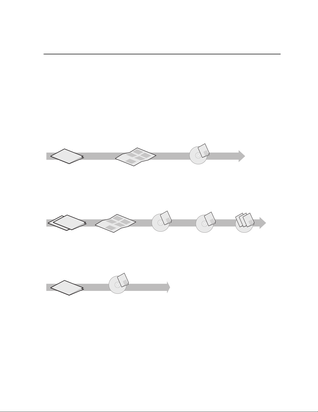
The following illustration shows the recommended order in which to reference the
documentation.
Path for the installer of K2 Media Client models with stand-alone storage
Grass Valley
K2 Manual
r
r
s
Se
e
s
Se
i
P
r
e
X
i
P
s
Se
r
X
f
e
o
i
P
Valley Group
s
Se
f
r
X
e
o
y
i
P
r
s
Se
l
f
X
e
y
i
o
s
Se
i
l
P
f
e
i
X
am
y
o
i
Grass
P
F
l
X
am
f
i
y
F
o
m
l
f
i
o
y
Fa
l
am
y
i
F
l
i
am
F
am
F
K2 Media Client
Release Notes
The latest information about the
hardware and software shipped
with the system. Packaged with
K2 Media Client.
t
r
ta
nt
S
ume
ck
Qui
is doc
you
K2
Th
ps
you
el
h
ps
you
el
h
ps
el
h
Quick Start Guide
The essential steps for installing
the K2 Media Client. Different
models each have their own
version, packaged with the K2
Media Client.
K2 Media Client
System Guide*
Specifications and
instructions for
system settings.
Documentation
CD
Path for the installer of the K2 Storage System with connected K2 Media Clients
ley
Val
Grass
K2 Manual
s
S
e
s
S
e
ri
XP
e
s
s
lley Group
ri
S
S
e
e
XP
f
e
s
i
i
s
S
o
e
r
r
S
e
f
XP
XP
e
e
s
o
y
s
ri
S
e
ri
S
XP
l
e
f
f
e
XP
e
y
s
s
i
i
o
o
ri
S
S
l
Valley Group
e
e
f
m
r
XP
f
e
i
XP
i
o
a
e
y
y
s
o
Grass Va
m
ri
r
S
F
l
l
e
f
XP
XP
a
f
e
e
y
s
i
i
o
y
S
F
o
l
e
m
ri
l
f
f
i
XP
am
e
y
i
o
o
Grass
y
m
ri
Fa
F
l
XP
l
a
f
e
i
am
y
y
i
F
o
m
F
l
l
f
m
i
i
o
a
y
Fa
m
F
l
am
a
y
F
F
l
mi
i
a
m
F
a
F
rt
t
a
t
n
e
S
k
c
Qui
u
docum
is
u
K2
Th
ps yo
yo
u
hel
ps
hel
ps yo
hel
Documentation
CD
ley
Grass Val
K2 Manual
Documentation
CD
K2 Media Client and
K2 Storage System**
Release Notes
The latest information
about the hardware and
software shipped with
the system.
Path for the operator
s
S
e
s
S
e
ri
XP
e
s
ri
S
e
XP
f
e
s
o
Valley Group
ri
S
e
f
XP
e
o
y
s
ri
S
l
e
f
XP
e
y
s
i
o
S
l
e
ri
f
i
XP
am
e
y
o
Grass
ri
F
l
XP
am
f
e
i
y
F
o
l
f
am
i
o
y
F
l
am
y
i
F
l
i
am
F
am
F
K2 Media Client
Release Notes
The latest information
about the hardware and
software shipped with
the system.
K2 Storage System
Cabling Guide**
Diagrams for
cabling K2 Storage
System devices.
Grass Valley
K2 Manual
Documentation
CD
K2 Media Client
User Manual*
Information for using the user
interface to record, play and
manage clips and to configure
channels.
K2 Storage System
Instruction Manual*
Instructions to
install/configure K2
Storage (SAN), with
K2 Media Client, K2
Media Server.
Find the K2 Documentation CD packaged with K2 Media
*
Clients and with K2 RAID Storage devices, primary chassis.
Find the Storage Release Notes and Cabling Guide
**
packaged with K2 RAID Storage devices, primary chassis.
K2 Media Client
System Guide*
Specifications and
instructions for
system settings.
Other Manuals*
Including:
-
Quick Start Guide
-
User Manual
- Service Manual
- RAID manuals
Documentation descriptions
Use the following descriptions to choose the other documentation you need as you
install, ope rate, and maintain your system.
ley
Grass Val
Grass Valley
Grass Valley
K2 Manual
K2 Manual
K2 Manual
Documentation
CD
July 31, 2008 K2 Lx0 RAID Instruction Manual 9
Page 10

Preface
K2 Storage System Release Notes
The release notes contain the latest information about the software shipped on your
system. The informat ion in this document includes software upgrade instructions,
software specifi cations and requi rements, feature changes from the pre vious releas es,
and any known problems. Because release notes contain the latest information, they
are printed out rather tha n included in the Documentation CD-ROM . You can find the
release notes packaged with the RAID storage chassis.
K2 Storage System Cabling Guide
The cabling guides provide diagrams for storage system cabling and external
configuration, su ch as setting addre sses on RAID devices. There is a cabling g uide for
each pre-defined level of K2 Storage System. Each cabling guide covers both
redundant and non-redund ant systems. You ca n find the cabl ing guide packag ed with
the primary RAID storage chassis.
K2 Media Client Quick Start Guides
The Quick Start Guides provides step-by-step installation instructions for basic
installation and operation of the K2 Media Client, including recording and playing
clips. You can find the Quick Start Guide for your par ticular model packaged with the
K2 Media Client.
Documentation CD-ROM
Except for the release notes and Quick Start guide, the full set of support
documentation, including this manual, is available on the Documentation CD-ROM
that you receive with your K2 Media Client. You can find the Documentation
CD-ROM packaged with the RAID storage chassis.
The Documentation CD-ROM includes the following:
K2 Storage System Instruction Manual — Contains installation, configuration, and
•
maintenance procedures for shared storage options.
•
RAID Instruction Manuals — There is an Instruction Manual for the RAID storage
device that can be a part of a K2 Media Client. This manual contains procedures
for configuring and servicing the device.
•
K2 Media Client System Guide — Contains the product specifications and
step-by-step instructions for modifying system settings. Includ es instruc tions for
adding a K2 Media Client to the K2 Storage System.
•
K2 Media Client User Manual — Describes the K2 Media Client and provides
instructions for configuring and operating the product.
•
K2 Media Client Service Manual — Contains information on servicing and
maintenance.
How this manual is organized
The K2 Lx0 RAID Stor age Instruc tion Manual is organized around th e tasks y ou’ll be
performing to install and service your K2 RAID External Storage System. You can
see this reflected in the chapter titles chosen for this manual. The following identifies
and describes the chapters included in this manual:
10 K2 Lx0 RAID Instruction Manual July 31, 2008
Page 11

Chapter 1, About the K2 Lx0 RAID
Introduces the K2 Lx0 RAID Storage. You can r ead t his chapter to get familiar with
the K2 Lx0 RAID external storage key features and components.
Chapter 2, K2 Lx0 RAID Installa tion Inform ation
Describes how to install a K2 Lx0 RAID Storage and K2 Lx0 Expansion Chassis,
including rack mounting. Refer to the K2 Storage System Instruction Manual for
connection and configuration information.
Chapter 3, Servicing the K2 Lx0 RAID
Describes how to replace FRUs, such as disk modules, and add disk modules and
redundant FRUs.
Chapter 4, K2 Lx0 RAID Technical Specifications and Operating Limits
This appendix consists of electrical and environmental specifications.
Glossary
The Glossary explains terms used throughout this manual.
Terminology used in this manual
In order to avoid confusion between the storage types, the following terms will be
used consistently throughout the K2 documentation:
Terminology used in this manual
Internal storage — K2 Media Client models with internal storage access their ow n
internal media storage drives, as a “stand-alone” system.
Direct-connect storage — K2 Media Client models with direct-connected (i.e. not
shared) storage ac cess their own external media stora ge driv es that are contained in a
Lx0 RAID chassis, and are also considered stand-alone systems.
Shared storage — K2 Media Client models with shared storage access RAID
protected media storage drives that are part of a K2 Storage System (SAN). The K2
Storage System incorporates one or more RAID chassis, such as K2 Lx0 RAID.
K2 Storage System — specifically refe rs to the shared K2 Storage System (SAN).
Stand-alone K2 Media Client — refe rs to K2 Media Clie nts with int ernal stor age or
direct-connect st ora ge.
Getting more information
Product information is readily available at the following sources:
On-line Help Sy st e m s
K2 Media Client Help — You can access the on-line help through the AppCenter user
interface as follows:
• In the menu bar select
drop-down menu.
Help, then choose AppCenter Help Topics from the
NetCentral Help — From the NetCentral interface access on-line help as follows:
• For general help with NetCentral manager, select
• For help specific to monitoring K2 Media Client system devices, select
Device Providers
July 31, 2008 K2 Lx0 RAID Instruction Manual 11
and then select the monitored device.
Help | NetCentral Help Topics.
Help |
Page 12

Preface
Thomson Grass Valley Web Site
This public Web site contains all the latest manuals and documentation, and
additional support information. Use the following URL.
http://www.thomsongrassvalley.com.
12 K2 Lx0 RAID Instruction Manual July 31, 2008
Page 13

Grass Valley Product Support
T o get technica l assistance, che ck on the status of a question, or to repo rt new issue, contac t
Grass Valley Product Support via e-mail, the We b, or by phone or fax.
Web Technical Support
To access support infor mation on the Web, v isit the pro duct support Web p age on the
Grass Valley Web site. Yo u ca n down loa d software or find sol ut ion s t o pr obl ems b y
searching our Frequently Asked Questions (FAQ) database.
World Wide Web: http://www.thomsongrassvalley.com/support/
Technical Support E-mail Address: gvgtechsupport@thomson.net.
Phone Support
Use the following information to contact product support by phone during business
hours. Afterhours phone support is available for warranty and contract customers.
Grass Valley Product Support
International
(France)
International
(United States,
Canada)
Hong Kong,
Taiwan, Korea,
Macau
Australia, New
Zealand
Central, South
America
China +861 066 0159 450 Netherlands +31 (0) 35 62 38 421
Belgium +32 (0) 2 334 90 30 Northern Europe +45 45 96 88 70
Japan +81 3 5484 6868 Singapore +65 6379 1313
Malaysia +603 7805 3884 Spain +41 487 80 02
Middle East +971 4 299 64 40 UK, Ireland, Israel +44 118 923 0499
+800 80 80 20 20
+33 1 48 25 20 20
+1 800 547 8949
+1 530 478 4148
+852 2531 3058 Indian
+61 1300 721 495 Germany, Austria,
+55 11 5509 3440 Near East, Africa +33 1 48 25 20 20
Authorized Support Representative
Italy +39 02 24 13 16 01
+39 06 87 20 35 42
Belarus, Russia,
Tadzikistan,
Ukraine,
Uzbekistan
Subcontinent
Eastern Europe
+7 095 258 09 20
+33 (0) 2 334 90 30
+91 11 515 282 502
+91 11 515 282 504
+49 6150 104 444
A local authorized support represent ative may be availabl e in your countr y. To locate the
support representat ive for your count ry, visit the pro duct support Web page on the Grass
Valley Web site.
July 31, 2008 K2 Lx0 RAID Instruction Manual 13
Page 14
Preface
14 K2 Lx0 RAID Instruction Manual July 31, 2008
Page 15
Chapter 1
Condor RAID
Chassis
Condor RAID
Expansion
Chassis
BBU IN MODEM
FLT/LNK
HPE
FLT
A/L
BACKUP
ACT/LNK
LNK/ACT
FLT
HP
5 4 3 2
RDY
LAN
BAT
MNT
ACS
MC
DP1 DP0
HP
1 0
BBU IN MODEM
FLT/LNK
HPE
FLT
A/L
BACKUP
ACT/LNK
LNK/ACT
FLT
HP
5 4 3 2
RDY
LAN
BAT
MNT
ACS
MC
DP1 DP0
HP
1 0
FLT/LNK
FLT RDY
DP-OUT
PS
FLT CLR
DP-IN
FLT/LNK
FLT RDY
DP-OUT
PS
FLT CLR
DP-IN
About the K2 Lx0 RAID
This chapter introduces the K2 Lx0 RAID Storage. Topics include:
• “K2 Lx0 RAID features” on page 15
• “K2 Lx0 RAID components” on page 16
• “K2 Lx0 RAID components” on page 16
K2 Lx0 RAID features
The K2 Lx0 RAID is a high performa nce, hig h availabili ty mass st orage syst em used
in K2 Lx0 and K2 Lx0 Expansion K2 Storage Systems. The K2 Lx0 chassis 4 Gb/s
host interface supports industry-standard technology.
The K2 Lx0 RAID has a minimum of two host ports per controller. Each chassis is
equipped with two power supplies. Individual high-speed SAS links connect drives.
Depending on your configuration, the K2 Lx0 RAID chassis contains:
• Two or six host ports
• Up to 12 SAS or SATA disk drives
• One or two hardware RAID Controllers in a 2U high rack-mountable chassis
July 31, 2008 K2 Lx0 RAID Instruction Manual 15
Page 16

Chapter 1 About the K2 Lx0 RAID
The K2 Lx0 RAID Expansion Chassis provides additional storage capacity. It
contains:
• Two Expansion Adapters
• Up to eleven K2 Lx0 RAID Expansion Chassis can be connected to a single K2
Lx0 RAID chassis
• A single disk-array storage system with up to 144 drives
K2 Lx0 RAID components
The K2 Lx0 RAID components are:
• One 2U high rack-mountable chassis
• One or two (K2 Lx0 RAID re dundant) RAID controller s or two expansion ad apters
(Expansion chassis)
• As many as twelve SAS 73GB or 300GB (15,000 rpm) or SATA 500 GB or 750
GB (7,200 rpm) disk drives per chassis
• Two RAID chassis power supplies
All configurations have SNMP ports, sl ots for prima ry and secondar y controllers, an d
chassis with redundant power. Any unoccupied sl ot (RAID controller or disk mod ule)
has a filler module to maintain air flow and compliance with electromagnetic
interferen ce (EMI) standards.
The RAID controllers, expansion adapters, disk drives and power supplies are
hot-swappable field replaceable units (FRUs), which means you can add or replace
them while the K2 Lx0 RAID is powered up.
An optional second RAID controller module in the K2 Lx0 RAID allows for
continued access to the K2 Lx0 RAID if the primary RAID controller fails. Refer to
the K2 Storage System Instruc tion Manu al for detaile d conn ection and conf igura tion
instructions.
16 K2 Lx0 RAID Instruction Manual July 31, 2008
Page 17
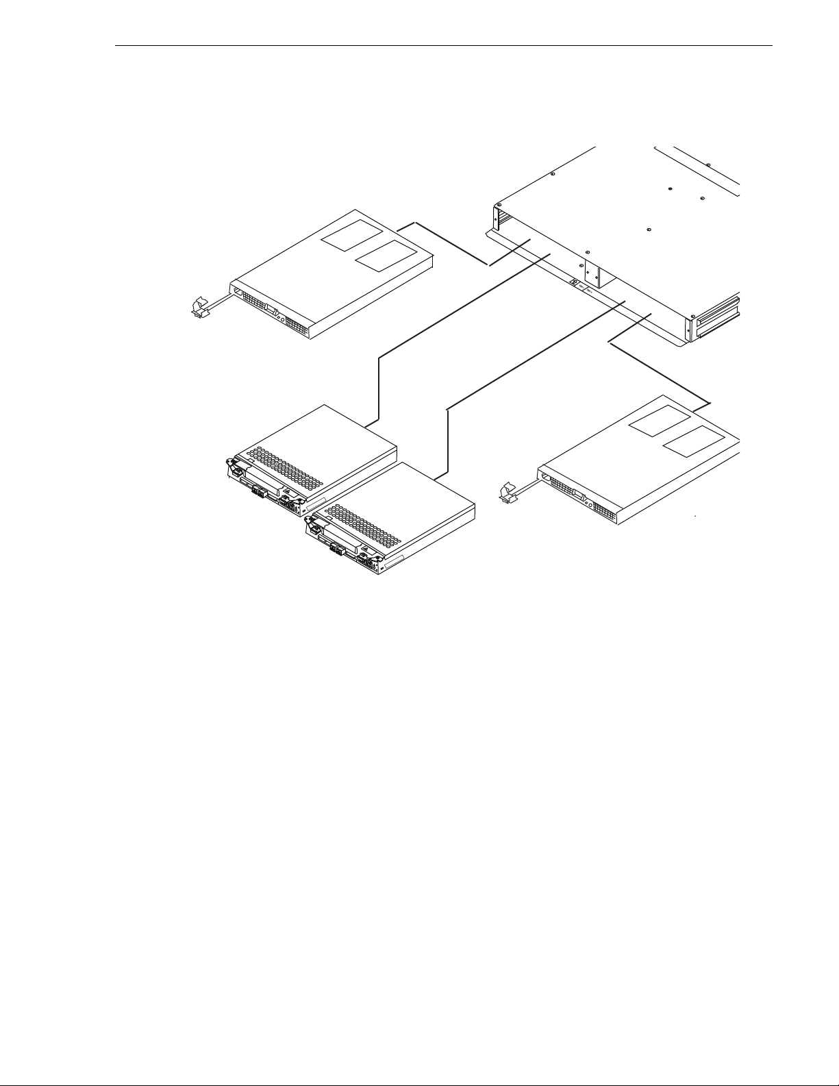
The following figure shows the RAID Storage Chassis components. Details on each
HOT
UNIT LABEL
HOT
UNIT LABEL
Controller 1
(or Expansion Adapter 1)
Controller 0
(or Expansion Adapter 0)
Power Supply 0
Power Supply 1
Chassis
component follow the figure.
Chassis
Chassis
K2 Lx0 RAID Circuit board modules
K2 Lx0 RAID Storage Chassis circuit board modules
July 31, 2008 K2 Lx0 RAID Instruction Manual 17
NOTE: Every K2 Lx0 RAID chassis controller includes a backup bat tery so tha t if
electrical power is lost, data stored in cache memory will be saved.
The chassi s is a sheet-metal housing that contains chas sis slots for the RAID
controllers or expansion adapters, disk drives, power supplies, and the LAN card.
There are two circuit board modules used: the RAID controller module and the
expansion adapter. The RAID controller module is in the primary RAID chassis. It
manages the disk drives and provide s an int er fa ce to th e K2 Media Serv er sys te m or
switch. The expansion adapter i s in an Expans ion chass is. It manag es the d isk drive s,
in conjunction with the conn ected RAID con trol ler and pr ovides an SAS interfac e to
the primary chassis.
The K2 Lx0 RAID includes one or two RAID controller modules. This provides
redundant host interface ports.
Page 18

Chapter 1 About the K2 Lx0 RAID
BBU IN MODEM
FLT/LNK
HPE
FLT
A/L
BACKUP
ACT/LNK
LNK/ACT
FLT
HP
5 4 3 2
RDY
LAN
BAT
MNT
ACS
MC
DP1 DP0
HP
1 0
BBU IN MODEM
FLT/LNK
HPE
FLT
A/L
BACKUP
ACT/LNK
LNK/ACT
FLT
HP
5 4 3 2
RDY
LAN
BAT
MNT
ACS
MC
DP1 DP0
HP
1 0
Modem
Connector
Ejector
HPE
Fault LED
HPE
BBU
Fault LED
Ejector
Power
Button
Extended BBU
Connector
SAS
Connector
HP Connector
LAN
Connector
Fault
LED
Ready
LED
Backup
LED
MNT
Connector
RAID
Controller1
RAID
Controller 0
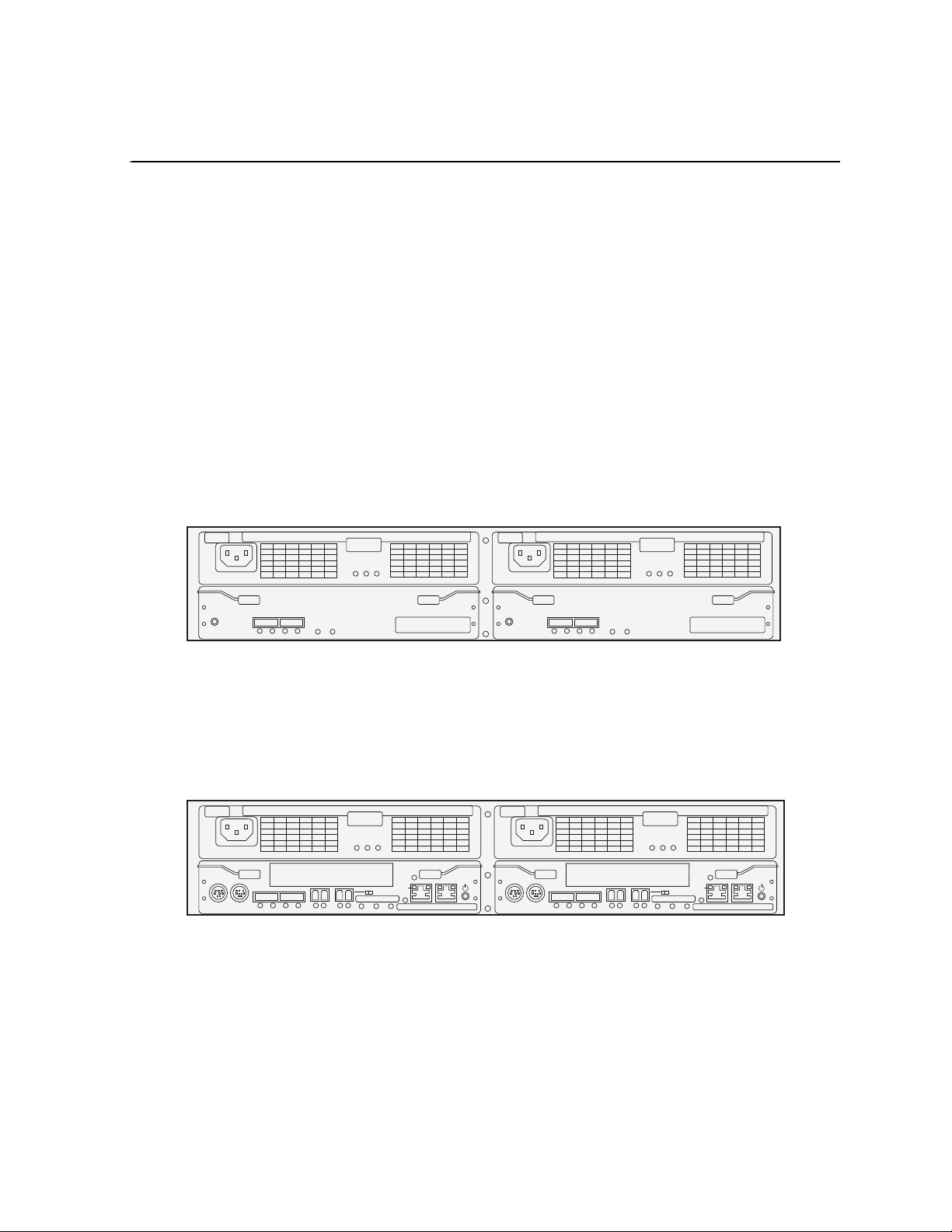
The following figure shows a K2 Lx0 RAID with the two RAID controller modules.
The RAID controller module has two host ports (HP0/HP1) and two Expansion
Chassis SAS ports (DL1/DL0). The Host ports require LCC cables (optical) for the
Fibre Channel connection to a K2 Media Server or to a Fibre Channel switch. The
Expansion Chassis Ports requi re SAS cables for the SAS connections with a K2 Lx0
Expansion Chassis. The re are two po rt st atus LEDs f or eac h Host por t and ea ch SAS
port. Refer t o “Interpreting controller status LEDs” on page 35.
When the redundant controller option is not installed in the K2 Lx0 RAID Storage
Chassis, a blank fills the other RAID controller slot.
K2 Lx0 Expansion
RAID Expansion Chassis circuit board modules
The K2 Lx0 Expansion RAID Expansion Chassis has two expansion adapters as
shown in the following fi gure.
Expansion Adapter 1 Expansion Adapter 0
Ejectors
RDY
FLT
Ejectors
PS
FLT CLR
FLT/LNK
DP-OUT DP-IN
RDY
FLT
PS Fault Clear Fault LED Ready LED
SAS Connector
The expansion adapter in the K2 Lx0 Expansion has two SAS ports: DP-IN and
DP-OUT. SAS cabling connec ts the DP-IN port to a K2 Lx0. There are two port status
PS
FLT CLR
DP-OUT DP-IN
FLT/LNK
PS Fault Clear Fault LED Ready LED
SAS Connector
LEDs for each SAS port. Refer to “Interpreting expansion adapter status LEDs” on
18 K2 Lx0 RAID Instruction Manual July 31, 2008
page 38.
Page 19

Power supplies
There are two auto-ranging power supplies, each with a power cord. Each supply
supports a fully config ured K2 Lx0 Exte rnal RAID an d shares load cur rents with the
other supply, if it is present . The po wer suppli es are designed s o as to prote ct the d isk
drives if you install th em while the K2 Lx0 External RAID is powered up. A disk with
power-related faul ts wil l not adversely affect the operatio n of any other disk.
Power supplies
Power
Supply1
Each power supply ha s s tat us LEDs vis ibl e from the rear panel . Th e status LEDs are
described in the “Interpre ting power sup ply status LEDs” on page 39. You can add or
remove one power supply in the RAID Storage Chassis while the RAID Storage
Chassis is powered up, but the operation must be completed within tw o minutes. Even
if a power supply is disabled, t he fan in the non-fun ctioning power supp ly can run off
the second power supply to cool the RAID for a couple of minutes.
Disk modules
Each disk module consists of a SAS or SATA disk drive in a carrier assembly. If a
disk drive fails, and needs replacing, you can do so while the RAID Storage Chassis
is powered up. Replacement disk drives begin rebuilding immediately after being
installed. (See “Removing and installing disk modules” on page 40.)
The following table shows how disk modules are identified based on the chassis
address and physical location. The chassis with an address set to 0 contains drives
from 00 to 0B; the expansion chass is are numbered X0 through XB, where X indicat es
the chassis number.
BBU IN MODEM
FLT/LNK
DP1 DP0
Power
HPE
FLT
HP
BAT
5 4 3 2
LAN
ACT/LNK
HP
1 0
A/L
BACKUP
FLT
MNT
LNK/ACT
MC
ACS
RDY
BBU IN MODEM
FLT/LNK
DP1 DP0
HPE
FLT
HP
BAT
5 4 3 2
LAN
ACT/LNK
LNK/ACT
HP
1 0
MC
A/L
ACS
BACKUP
RDY
FLT
Supply 0
MNT
00 01 02 03
04 05 06 07
08 09 0A 0B
For information on cabli ng expa nsion c has sis, s ee the K2 Stor age Sys tem Ins truct ion
Manual
An operating primary RAI D chassis must ha ve, at a minimum, the first three physi cal
drives (00 - 02) installed, as the RAID configuration information is written to these
drives. Microcode is also written to these disks when RAID controller microcode is
loaded.
The SAS and SATA disk drives are shown in the following illustrations. The SATA
drive has an adapter to fit it to the K2 Lx0 RAID Chassis.
July 31, 2008 K2 Lx0 RAID Instruction Manual 19
Page 20

Chapter 1 About the K2 Lx0 RAID
7
5
0
G
B
7
200
rp
m
S
A
T
A
SATA to SAS adapter
SAS disk drive
SATA disk drive
20 K2 Lx0 RAID Instruction Manual July 31, 2008
Page 21

Chapter 2
K2 Lx0 RAID Installation Information
This chapter describes information you’ll need to install the K2 Lx0 RAID Storage
(K2 Lx0 Expansion Chassis). Major topics are:
• “Installation requirements”
• “Installing a K2 Lx0 RAID in an equipment rack”
• “K2 Lx0 RAID power-up and initialization”
• “K2 Lx0 RAID power-down”
Installation requir ements
This section describes the following requirements:
• “Site requirements” on page 21
• “Cabling requirements” on page 21
• “Cabling requirements” on page 21
• “Binding disk modules into groups” on page 22
Site requirements
For proper K2 Lx0 Expansi on Chassis operation , the installat ion site must conf orm to
certain environmental specifications. These are detailed below and in Cha pt er 4, K2
Lx0 RAID Technical Specifications and Operating Limits.
Power
Refer to “Data handling specification s” on page 49 for AC power requirements. If one
of the two power suppli es fail s, the remainin g power su pply and cor d can support the
full load. You must use a rack mount cabinet with AC power distribution, and have
main branch AC distribut ion tha t can han dle the se va lues fo r the numbe r of K2 Lx0s
and K2 Lx0 Expansion Chassis units that you will interconnect.
Cooling
Make sure your si te has air condition ing of th e correct size and placement to maintain
the specified ambient te mperatu re range. The air cond itio ning must be able to handle
the requirements of the K2 Lx0s and any conne cted K2 Lx0 Exp ansions as indi cated
under “Environmental limits” on page 50.
Cabling requirements
It is recommended that you use the cables shipped with your K2 Lx0 RAID when
making connections. For cable specifications, refer to “Cable lengths” on page 50.
Host cables must meet the appropriate 4-Gbit HPA compliance standards.
NOTE: Also refer to the K2 Storage System Instruction Manual for cabling
diagrams and step-by-step instructions.
July 31, 2008 K2 Lx0 RAID Instruction Manual 21
Page 22

Chapter 2 K2 Lx0 RAID Installation Information
!
Binding disk modules into groups
After cabling a K2 Lx0 RAI D and any K2 Lx0 Expansion Cha ssis, you must bind di sk
modules using the Storage Utility provided by Grass Valley. Once bound, the order
of the drives is importan t. Do not re arran ge drive s once th ey have be en bou nd. Refer
to the K2 Storage System Instruction Manual for information on using the Storage
Utility to bind drives.
Installing a K2 Lx0 RAID in an equipment rack
Use the information in thi s sectio n to unpack the K2 Lx0 RAID chassis a nd mount in
an equipment rack.
Procedures include:
• “Unpacking the chassis”
• “Installing the rack mounts”
• “Inserting the K2 Lx0 RAID chassis in the rack”
Unpacking the chassis
Unpack the K2 Lx0 RAID chassis, cables, and installation kit, as illustrated by the
diagram on the outside of the packing box.
CAUTION: A K2 Lx0 RAID chassis is heavy. Three people
should lift and move it.
NOTE: Save the chassis packaging. Use only K2 approved packaging to ship.
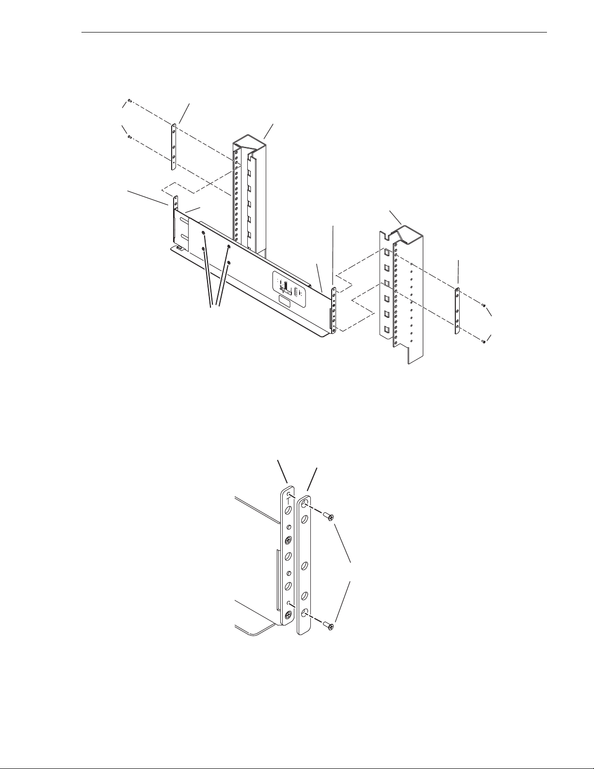
Installing the rack mounts
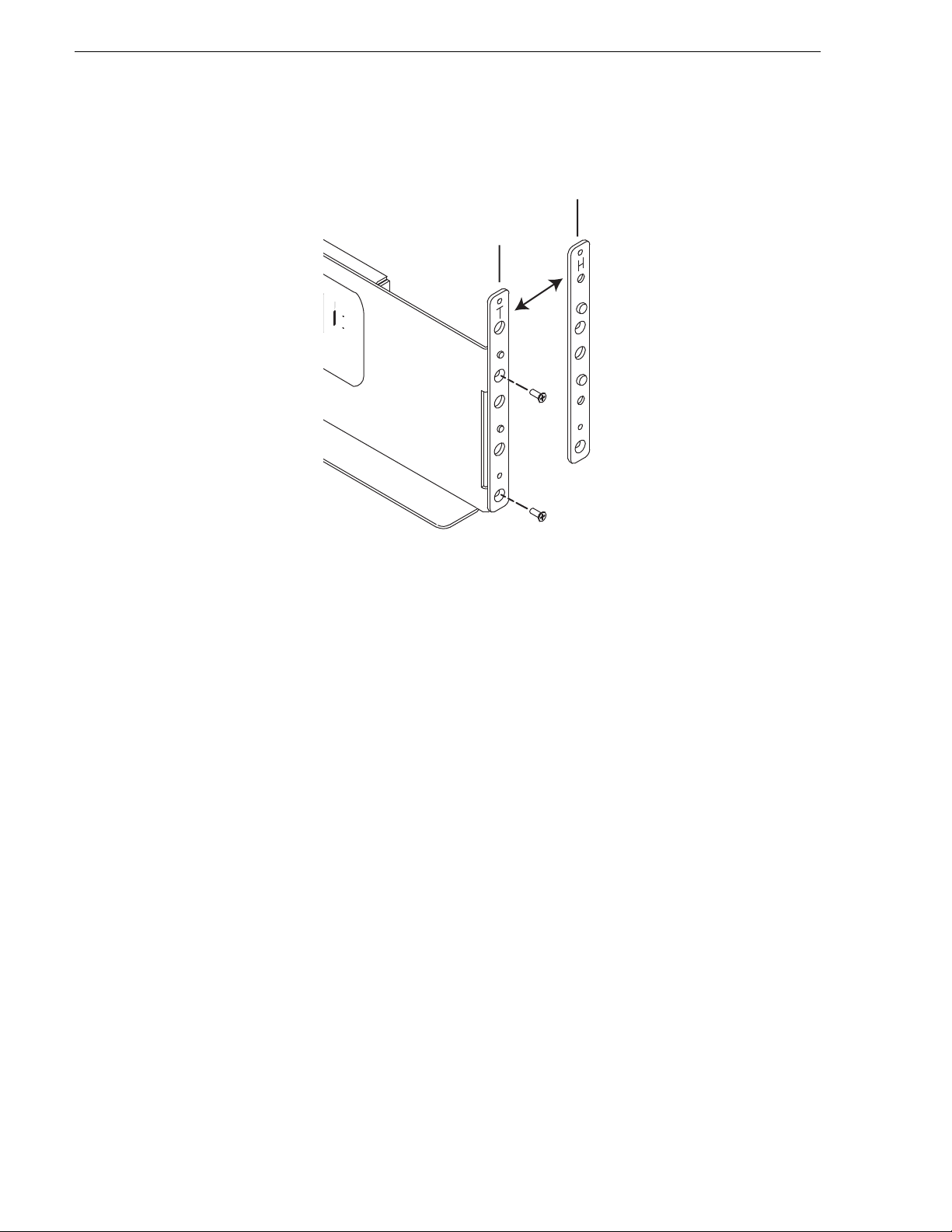
The following diagram and procedure describe installing the right side rail.
Installation is similar fo r the left side rail.
22 K2 Lx0 RAID Instruction Manual July 31, 2008
Page 23
Installing the rack mounts
Front
channel
mount
Inner
rail
Rail
adjustment
screws
Outer
rail
Guide
Bracket
(Type T for
threaded holes,
Type H for
round holes)
Rack
Bracket
Rack
Bracket
Guide
Bracket
(Type T for
threaded holes,
Type H for
round holes)
Back
channel
mount
M3
screws
M3
screws
FrontFront
channelchannel
mountmount
InnerInner
rail rail
RailRail
adjustmentadjustment
screwsscrews
OuterOuter
railrail
GuideGuide
BracketBracket
RackRack
BracketBracket
RackRack
BracketBracket
GuideGuide
BracketBracket
Back Back
channelchannel
mountmount
Guide
Bracket
Rack
Bracket
M3
screws
To install the K2 Lx0 RAID rack mounts:
1. Remove the rack br ackets from t he guide brack ets at both e nds of the rai l. Save th e
rack brackets and the M3 screws, as they are used later in this procedure.
2. If your rack has 10- 32 threade d holes, ski p ahead to the next st ep in thi s procedure.
If your rack has 0 .281- i nch round holes, at bo th ends of the rail repl ac e t he T type
guide brackets with the H type guide brackets.
July 31, 2008 K2 Lx0 RAID Instruction Manual 23
Page 24
Chapter 2 K2 Lx0 RAID Installation Information
Rack
Bracket
Rack
Bracket
Guide
Bracket
T type
Guide
Bracket
H type
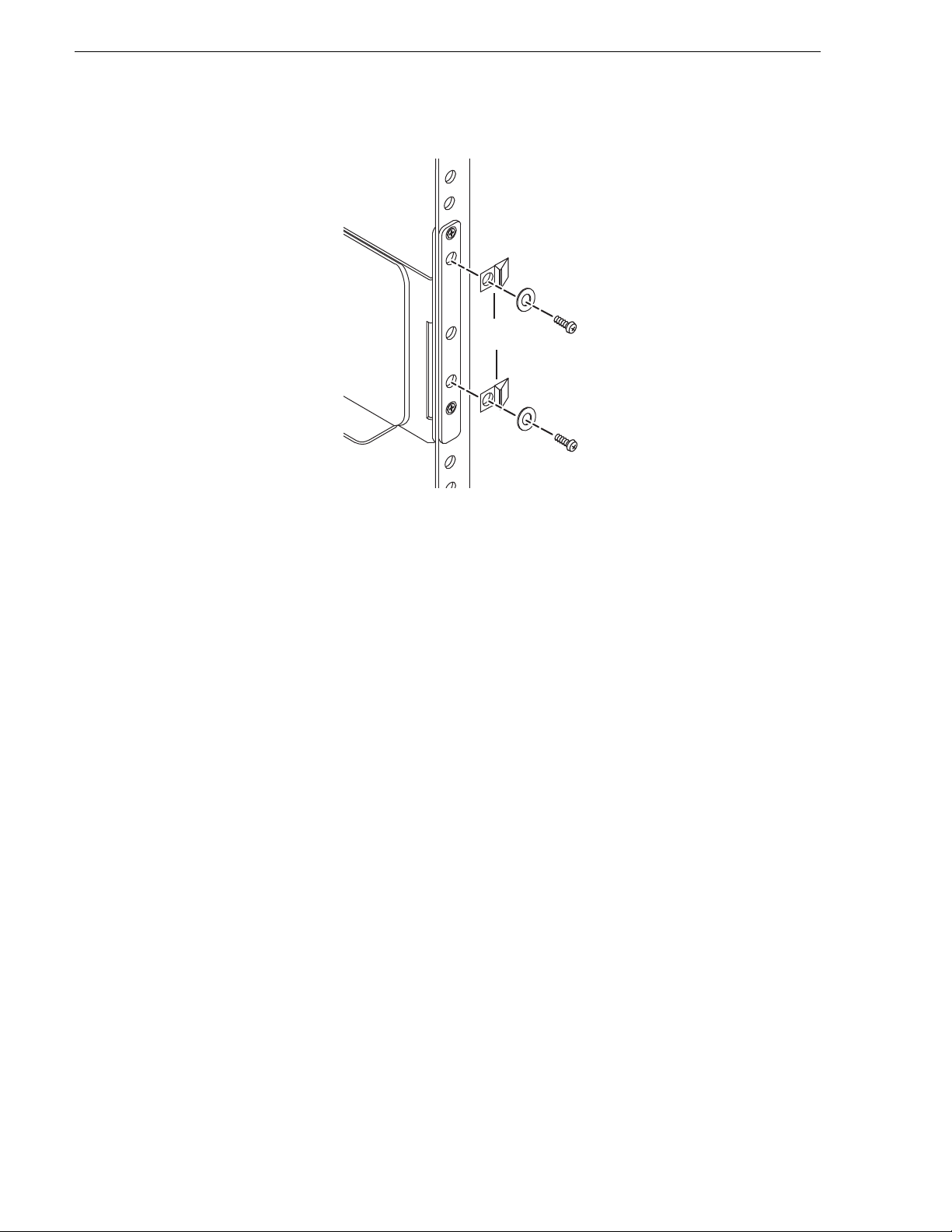
3. Loosen the rail adjustment screws so that the inner rail slides free ly.
4. Align the mounting holes on the outer rail guide bracket with the front channel
mount holes. The protrusions on the guide bracket guide the rail to appropriate
positions on the rack.
5. Place the two M3 mounting screws through the rack bracket, through the front
channel mount holes, a nd into the mounting holes on the guide brac ket. Tighten the
screws to secure the outer rail to the front channel mount.
6. Move to the r ear of the rack and pull th e inner ra il toward you to ali gn the inne r rail
guide bracket mou nting holes with the b ack channe l mount hole s. The pr otrusi ons
on the guide bracket guide the rail to appropriate positions on the rack.
7. Place the two mounting screws throu gh the rack bracke t, through the back channel
mount holes, and i nto the mounting holes on the gui de bracke t. Tigh ten the screws
to secure th e outer rail to the back channel mount.
8. Firmly tighten the rail adjustment screws.
9. Repeat this procedure for the other side rail.
Inserting the K2 Lx0 RAID chassis in the rack
1. Rest the chass is on t he supp ort an gle s shown. S lide t he cha ssis b ack and in to p lace
2. Secure the chassis to the rack with the 10-32 mounting screws. On racks with
threaded holes the mounting screws engage the rack’s threaded holes. On racks
without threaded holes the mounting scr ews enga ge the H type guide bracke t’ s
threaded holes.
24 K2 Lx0 RAID Instruction Manual July 31, 2008
Page 25

Support
angle
Inserting the K2 Lx0 RAID chassis in the rack
3. At the rear of the rack, insert and tighten the 10-32 mounting screws, with cable
clamps, through the rear rack bra ckets. On racks with threa ded holes the mounting
screws engage the rack’s threaded holes. On racks without threaded holes the
mounting screws engage the H type guide bracket’s threaded holes.
July 31, 2008 K2 Lx0 RAID Instruction Manual 25
Page 26
Chapter 2 K2 Lx0 RAID Installation Information
Cable
clamps
The 10-32 screws in the rear provide necessary re inforcement to the M3 screws.
4. Secure the two front rail brackets to the front rails with four M5 s crews, two on
either side. Place the screws above and below the chassis protrusions as shown in
the following diagrams.
26 K2 Lx0 RAID Instruction Manual July 31, 2008
Page 27

Front rail
Bezel
Front rail bracket
Release
catch
Chassis protrusions
brackets
Inserting the K2 Lx0 RAID chassis in the rack
5. To install the Grass Valley bezel to the front of the chassis, slide the bezel directly
on to the front r ail brackets. To re move the bezel, press the release ca tches on either
side of the bezel and pull it straight back.
6. Repeat this procedure to insert each K2 Lx0 RAID chassis in the rack.
July 31, 2008 K2 Lx0 RAID Instruction Manual 27
Page 28

Chapter 2 K2 Lx0 RAID Installation Information
!
!
K2 Lx0 RAID power-up and initializatio n
This section gives information about connecting power and powering-on the
K2 Lx0 RAID system.
Connecting electrical cables
For each chassis, there are two electrical cables (one for each power supply) that
should be connected to separate outside power sources.
WARNING: Make sure the power cords meet lo cal safety and electric al
standards.
CAUTION: The K2 Lx0 RAID system must be electrically grounded.
Operating the system without proper grounding can damage disk
drives. If the outlet you use is not grounded, make sure that a licensed
electrician replaces it and installs a grounding conductor.
To prevent the plug from being inadvertently discon nected, secure the elect rical cable
into the outlet by doing the following:
1. Check that the power switch on the RAID chassi s and those on the host syste m are
all set to OFF .
2. Insert the power cord into the power supply.
3. Secure the power cord with the power cable clamp.
4. Insert the plug of the power cord into an AC outlet. Use a grounded AC outlet.
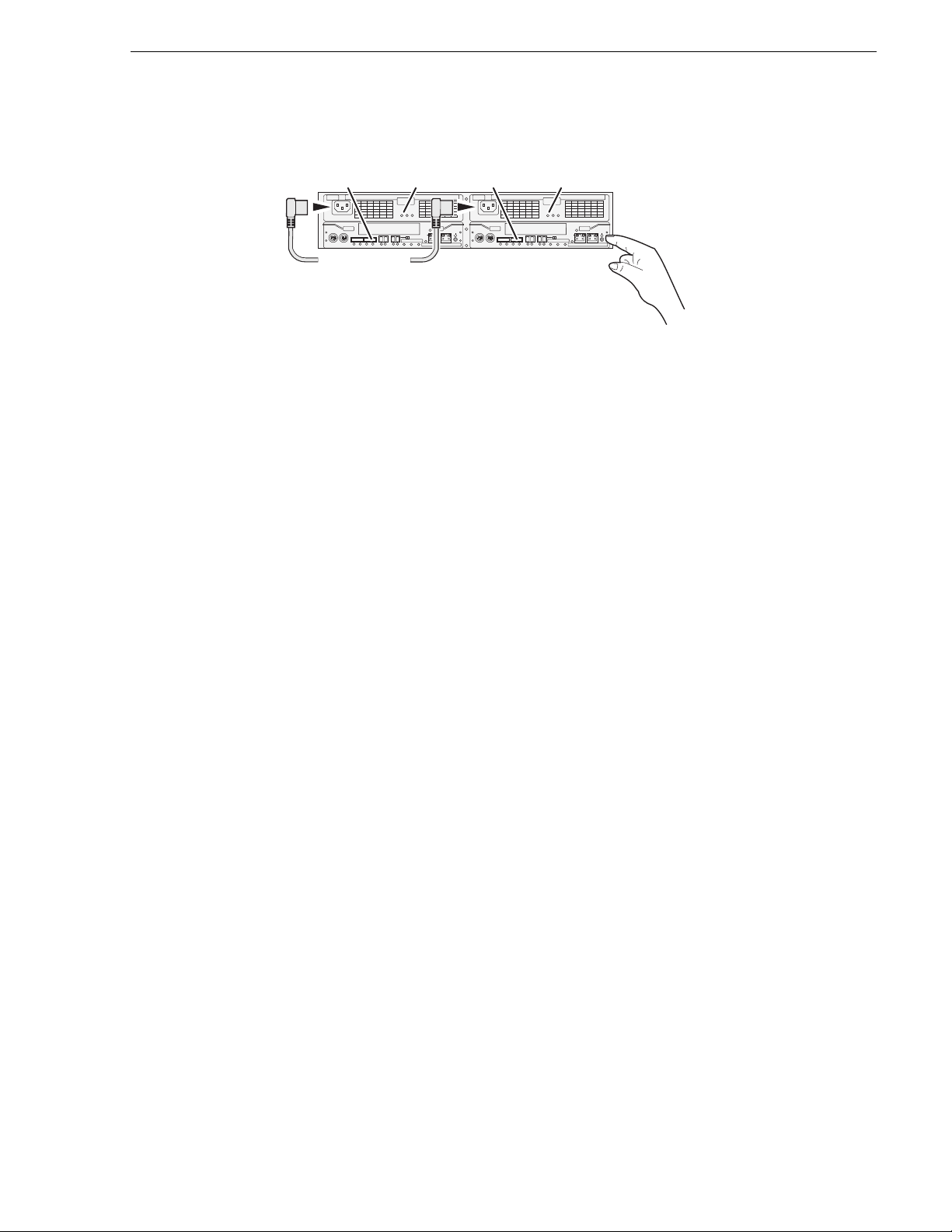
Powering-up the K2 Lx0 RAID system
1. Verify power and cabling.
2. Press and hold down the power button on the controller, as shown.
28 K2 Lx0 RAID Instruction Manual July 31, 2008
Page 29
K2 Lx0 RAID power-down
RDY
LED
BBU IN MODEM
Power Good
HPE
FLT
DP1 DP0
FLT/LNK
A/L
LED
HP
5 4 3 2
ACT/LNK
HP
1 0
BACKUP
FLT
RDY
LAN
LNK/ACT
MC
ACS
RDY
LED
BAT
MNT
BBU IN MODEM
DP1 DP0
FLT/LNK
Power Good
LED
HPE
FLT
HP
5 4 3 2
ACT/LNK
LNK/ACT
HP
1 0
MC
A/L
BACKUP
FLT
RDY
BAT
LAN
MNT
ACS
Power Cords
(115V/230V)
If the RAID chassis has two controllers, you can press the power button on either
controller. You do not need to press both power buttons.
Pressing the power b utton on a cont roller also powers o n any connected Expansion
chassis. There are no power buttons on Expansion chassis.
3. Release the power button when the Power Good LED on the power supply is
illuminated. This takes 1-3 seconds .
4. Wait while th e primary RAID chassis performs self-test and initialization . This
takes about four minutes. While this is taking place, the RDY LED is illuminated
with a steady on light.
5. Watch for the RDY LED to b egin blinking a t one second inter vals. The LED might
turn off and back on two times before st arti ng the one second bli nk patt ern. When
the RDY LED is blinking at one second interval s, the sel f-test and initi aliza tion is
complete and the chassis is ready for use.
Refer to sections in Chapter 3, “Servicing the K2 Lx0 RAID” for information on
interpreting status LED behavior.
NOTE: Refer to the K2 Storage System Instruction Manual for complete system
power-up procedures.
K2 Lx0 RAID power-down
NOTE: If your K2 Lx0 RAID system is part of a shared stora ge system , refer to the
K2 Storage System In struction Manual for instructions on shutting down the shared
storage before powering down a K2 Lx0 RAID.
To power-down the K2 Lx0 RAID correctly:
1. Stop all read/write activity to the K2 Lx0 RAID storage system.
2. On the primary RAID controller chassis, press and hold down the power button.
3. Release the power button in about 5 seconds, when the RDY LED blinks more
quickly, at a rate of about 2 blinks per second.
NOTE: Do not hold down the power button for longer than 15 seconds.
The power is turned of f for the prima ry and expansion RAIDs. P ower-off normall y
occurs within 20 seconds. It is indicated whe n LEDs other than t hose on the power
supplies go off and the fans stop rotating.
July 31, 2008 K2 Lx0 RAID Instruction Manual 29
Page 30

Chapter 2 K2 Lx0 RAID Installation Information
To turn on power, refer to “K2 Lx0 RAID power-up and initialization” on page 28.
Battery Backup
Every K2 Lx0 RAID chassis power supply includes a backup battery so that if
electrical power is lost, data stored in cache memory will be saved.
30 K2 Lx0 RAID Instruction Manual July 31, 2008
Page 31

Chapter 3
Servicing the K2 Lx0 RAID
This chapter describes how to monitor K2 Lx0 External RAID status and replace
Field Replaceable Units (FRU).
Topics include:
• “Maintenance procedures using Grass Valley Storage Utility” on page 31
• “Monitoring K2 Lx0 External RAID status using NetCentral” on page 31
• “Interpreting disk module LEDs” on page 34
• “Interpreting controller status LEDs” on page 35
• “Interpreting expansion adapter status LEDs” on page 38
• “Interpreting power supply status LEDs” on page 39
• “Removing and installing disk modules” on page 40
• “Replacing a RAID controller or expansion adapter” on page 43
• “Replacing a power supply” on page 44
Maintenance procedu res using Grass Vall ey Storage Utility
Several maintenance procedures can be performed using the Grass Valley Storage
Utility.
To perform t he following tasks, refer to the K2 Storage System Instruction Manual:
• Checking RAID controller microcode version
• Loading RAID controller microcode
• Identifying disk modules prior to removal
• Downloading K2 Lx0 Expansion disk drive firmware
• Disabling a K2 Lx0 Expansion RAID controller for removal
• Disabling a K2 Lx0 Expansion disk module for removal
• Configuring K2 Lx0 Expansion network and SNMP settings
Monitoring K2 Lx0 External RAID status using NetCentral
You can monitor K2 Lx0 External RAID Storage systems using Grass Valley’s
NetCentral monitoring software. Enabled by SNMP, NetCentral can continuously
monitor the storage system and send notifications if there is a problem. The SNMP
agent software required for NetCentral monitoring resides on the RAID storage
device itself. As a resul t , the K2 Lx0 External RAI D appears in NetCentral as a
standalone device rather than as a subsystem of the K2 Media Client.
July 31, 2008 K2 Lx0 RAID Instruction Manual 31
Page 32

Chapter 3 Servicing the K2 Lx0 RAID
!
K2 SAS STORAGE
Service LED
Label identifies whether the RAID
uses SAS or SATA disks
Service
LED
Power
LED
Disk drive
Active/Fault LEDs
Indicates the status of the disk drive
located to the right.
Indicates the status of the disk drive
located to the left.
Communication with NetCentral takes place over the Ethernet connection on each
RAID controller. To monitor the K2 Lx0 Externa l RAID, you must connect netw ork
cabling, power on the system, then configure network and SNMP settings as
described in the K2 Storage System Instruction Manual.
Refer to the N etCentral O n-line Help for information on monitoring the K2 Lx0
RAID with NetCentral.
Interpreting front panel LEDs
Use the following illustrat i ons (with and without the bezel) and table to ident if y and
interpret front panel LEDs.
With the bezel on, only the Service LED is visible on the front panel.
With the bezel off, the Power LED and Active Fault LEDs are visible.
32 K2 Lx0 RAID Instruction Manual July 31, 2008
Page 33

Primary and Expansion RAID chassis
Interpreting front panel LEDs
Operating
Condition
Power
LED
Service
LED Meaning
Running On Off Normal operation
On On Requesting maintenance or processing a mai nt enance task,
such as system recovery.
On On Requesting maintenance or processing a maintenance task
(such as system recovery). Further information provided via
NetCentral.
Starting upOn Flash (Primary RAID only) One of the following sequences are in
progress:
Power-on
Online download
Automatic download
To identify the sequence, use the controller’s Ready and
Fault LEDs. Do not turn off the power supply while a
sequence is in progress. For more information, see “K2 Lx0
RAID power-up and initialization” on page 28.
Shutting
down
On Flash (5 sec.)
and Off (7 sec.)
Flash
Off (Primary RAID only) Shutdown sequence is in progress.
(.2 sec)
(Primary RAID only) Requesting maintenance. (Battery
backup failure, ca c he write data may have be en los t)
and
Off (.7
sec)
Off Off Shutdown sequence is complete.
July 31, 2008 K2 Lx0 RAID Instruction Manual 33
Page 34

Chapter 3 Servicing the K2 Lx0 RAID
Service
LED
Power
LED
Disk drive
Active/Fault LEDs
Indicates the status of the disk drive
located to the right.
Indicates the status of the disk drive
located to the left.
Interpreting disk module LEDs
Use the following illustration and table to identify and interpret disk module LEDs.
For each disk drive or dummy car rier , a si ngl e Act ive /Fa ult LED indicates the states
of the disk drive.
Active/Fault LED Meaning
Green On Normal state (ready)
Green Blinking Normal status (accessing)
Green/
Orange
Orange only Blinking HDD low power state
Orange On Abnormal status
Blinking in
turn
Rebuilding
34 K2 Lx0 RAID Instruction Manual July 31, 2008
Page 35
Interpreting controller status LEDs
BBU IN MODEM
FLT/LNK
HPE
FLT
A/L
BACKUP
ACT/LNK
LNK/ACT
FLT
HP
5 4 3 2
RDY
LAN
BAT
MNT
ACS
MC
DP1 DP0
HP
1 0
BBU IN MODEM
FLT/LNK
HPE
FLT
A/L
BACKUP
ACT/LNK
LNK/ACT
FLT
HP
5 4 3 2
RDY
LAN
BAT
ACS
MC
DP1 DP0
HP
1 0
Modem
Connector
(10)
Ejector (11)
HPE
Fault LED
(12)
HPE (13)
BBU
Fault LED
(14)
Ejector (11)
Power
Button (1)
Extended BBU
Connector
(9)
SAS
Connector
(8)
HP Connector
(7)
LAN
Connector (3)
Fault
LED (5)
Ready
LED (4)
Backup
LED (6)
MNT
Connector (2)
RAID
Controller
ACS(15)
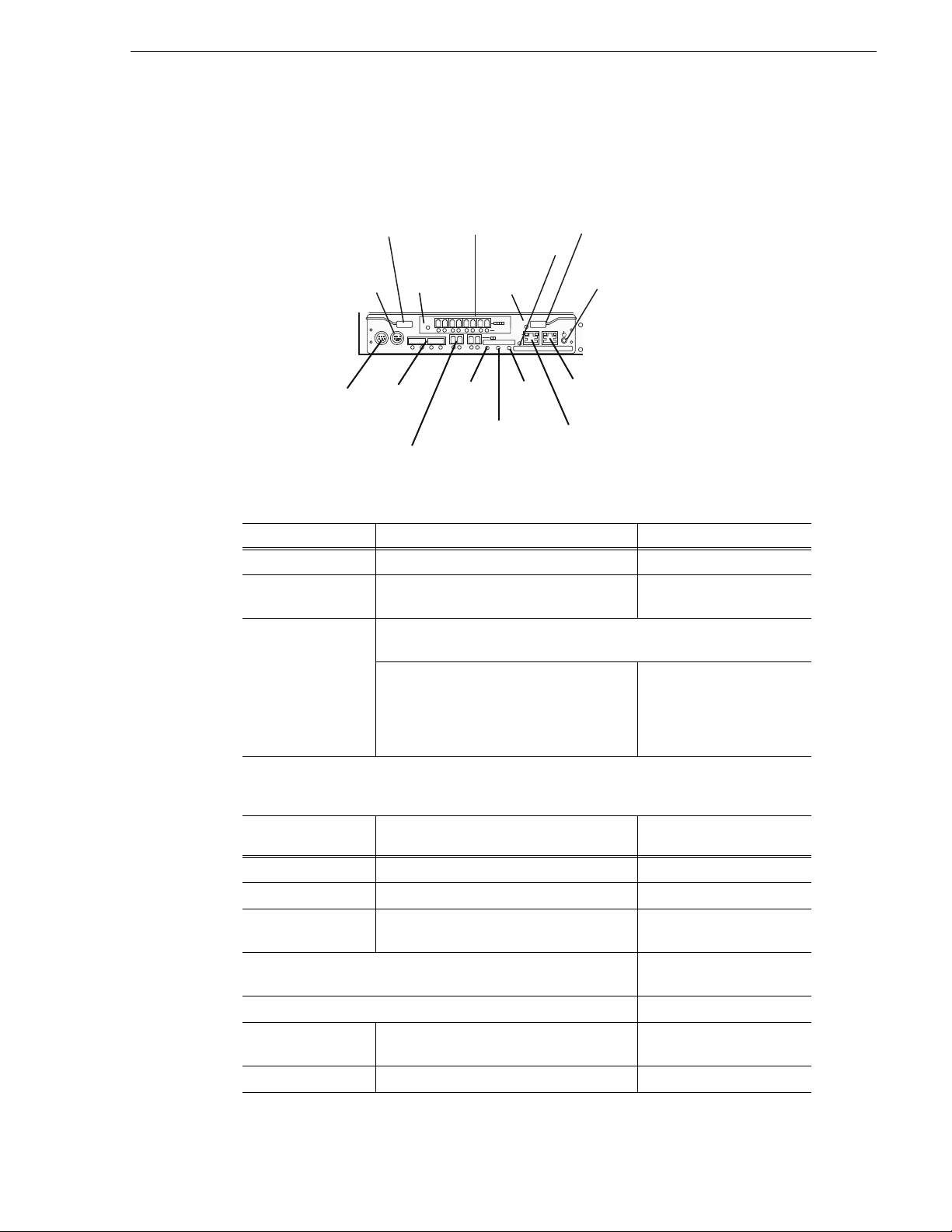
Interpreting controller status LEDs
Use the following illustration and table to identify and interpret controlle r LEDs.
Indicator Description
Power button (1) Turns power on and off
MNT connector (2) Connects the contro ller to a maintenance
PC
LAN connector(3) Connects the controller to a Storage Manager or a LAN for SNMP.
On the left is the LINK LED (green), which
indicates that a LAN is physically
connected.
On the right is the Active
LED (orange), which
illuminates during a TCP
protocol connec tion from a
host.
Ready LED (4)
(green)
Fault LED (5)
(orange)
Meaning
Blinking Off Normal operation
On Off Starting
Blinking (5 times/
second)
Blinking asynchronously Online/automatic download
Blinking sync h r on ou s l y In download mode
Blinking On Disk interface is
On On Occurrence of fault
Off Shutdown sequence in
progress
sequence in progress
unavailable
July 31, 2008 K2 Lx0 RAID Instruction Manual 35
Page 36

Chapter 3 Servicing the K2 Lx0 RAID
Ready LED (4)
(green)
Fault LED (5)
(orange)
Meaning
On Blink in g Waiting for disk enclosure
power-on
Off Off Powered off
Indicator Description
Backup LED (6) Blinks or ange light to indicate the batt e ry
backup state
Blinks if the controller has
lost power, was improperly
shut down, or faulted, with
data in its cache that has not
been written to disk. These
conditions need to b e
rectified before the backup
battery discharges (about 24
hours).
HP connector (7) Connects the disk array unit to a host.
Without an expansion port, there are two
ports per controller. With an expansion port,
there are six ports per controller.
On the left is the Access LED, which shows
the state of I/O processing. On the right is
the Link LED, which shows the state of the
FC link.
Locations and port numbers
HP5 HP4 HP3 HP2
Both LEDs blinking in a
one-second cycle shows the
port if offline
Both LEDs blinking
quickly (500ms cycle)
shows the shutdown
sequence is in progress.
Any other simultaneous
blinking shows that the port
setting is not correct.
HP1 HP0
SAS connector (8) Connects the K2 Lx0 RA ID to expansion chassis. Two connectors per
controller.
Locations and port numbers
DP1 DP0
(Optional) DP1 — only used with the L e vel 30 and Level 30R RAID
Link LED (green) Illuminates to indicate that
the link-up is being
executed on the Expansion
chassis.
Off state indicates that
the link-down is being
executed on the Expansion
chassis
Fault LED (orange) Illuminates to indicate an
error.
Extended BBU
Not used.
connector (9)
Modem connector
Not used.
(10)
Ejector (11) Used to install or remove the controller.
36 K2 Lx0 RAID Instruction Manual July 31, 2008
Page 37
Indicator Description
Interpreting controller status LEDs
HPE Fault LED (12)
(Orange)
HPE (13) (Optional) Expands the HP connector. Only used with the Level 30 and
BBU Fault LED(14)
(Orange)
ACS (15) Not used
(Optional) Illuminates to indicate an ab normality in the host port extensi on.
Only used with the Level 30 and Level 30R RAID
Level 30R RAID
BBU Fault LED Illuminates to indicate that
an error has occurred in the
battery backup unit (BBU).
Blinks to indicate that the
BBU must be replaced (due
to its life).
For more information, see
“Replacing a battery” on
page 45
July 31, 2008 K2 Lx0 RAID Instruction Manual 37
Page 38

Chapter 3 Servicing the K2 Lx0 RAID
Interpreting expansion adapter status LEDs
Use the following illustration and table to identify and interpret expansio n adapter
LEDs
Ejectors
PS
FLT CLR
FLT/LNK
DP-OUT DP-IN
RDY
FLT
PS Fault Clear Fault LED Ready LED
SAS Connector
Ready
LED
Off Off No connection or powered off. (The K2 Lx0 Expansion Chassis is powered
On Off Normal operation
Blinking Off Starting
On On Fault inside the adapter, must be replaced.
Connector Description
SAS Connects the adapter to a K2 Lx0 RAID or K2 Lx0 Expansion Chassis. A
Fault
LED
Meaning
on when the connected K2 Lx0 RAID is tu rned on.)
Fault LED and Link LED are located below each connector.
Fault LED (green)
Illuminated - indicates link-up
Off - indicates link-down
Link LED (orange)
Illuminated or blinking indicates that an abnormality was detected.
Off - normal operation
Locations and names of SAS connectors
DP-IN - connects to controller or adapter on the side near the controller
DP-OUT - connects to adapter of next disk en closure
Ejectors Used to install or remove the adapter.
PS Fault
Used to clear the fault status of the corres ponding power supply.
Clear
38 K2 Lx0 RAID Instruction Manual July 31, 2008
Page 39

Interpreting power supply status LEDs
Power plug (1) Ejector (5)
Power cable clamp (6)
Power Good LED (2) Fan Fault LED (4)
Power Fault LED (3)
!
Interpreting power supply status LEDs
Use the following illustration and table to identify and interpret power supply LEDs
.
LED Action Meaning
Power
Good
(green)
Power
Fault
(orange)
Fan Fault
(orange)
On AC power is supplied to the chassis.
On Faul t in power supply (excluding the fan) or ba ttery backup unit. This
LED works when AC power of either PS0 or PS1 is supplied.
On Fault in the fan. This LED works when AC power of either PS0 or PS1 is
supplied.
Moving disk modules
• The disk module must be unbound.
• Moving a drive module that is part of a LUN to another slot makes all information
• You must remove and install the disk module while the storage system is powered
• In a location that does not mount a disk drive, mount a dummy carrier. It is
A disk module must be inserted all the way or remov ed ent ir el y. Do not leave a disk
module partially removed except for periods when you are allowing it to spin down.
When replacing multiple disks, observe the following:
CAUTION: Once bound and added to file system, d on’t re- arrange the
disk modules and change the discovery order. You can destroy the
media file system beyond recovery if you move a disk module to a
different slot. The service person can move a disk module when you
don’t care about losing the media in the media file system and under
the followin g cautions:
on the LUN inaccessible.
up.
necessary for the cooling of the unit.
July 31, 2008 K2 Lx0 RAID Instruction Manual 39
Page 40

Chapter 3 Servicing the K2 Lx0 RAID
!
• The RAID chassis configuration information is w ritten to the first three disk
modules. If all of these disk modules are rep laced with new device s with the power
supplies turned off, the information is lost. This condition is indicated by the
SERVICE LED blinking at a high rate at chassis power up. Therefore, do not
replace the first three d isk modules wit h the power su pplies turn ed off. Do n ot take
out more than one of the disk dr ives inserted in locat ions 00, 01, and 02 at one time.
• When multiple disk modules are subject to replacement, they must be replaced
with new disk modules one by one. Do not replace multiple disk modules
simultaneously. After checking that the Ready LED on the front panel of the
current disk module is lit, commence replacing the next disk module.
• Stick on the physical label indicating the installation position on each newly
installed disk module.
CAUTION: Handle a disk module gently and use an ESD wristband.
Do not remove a faulty disk module until you have a replacement
module (with the same part number) or a filler module available.
Removing and installing disk modules
Use the following instructions to replace a faulty disk module. It should be replaced
while the RAID chassis is running (hot-swapped).
Removing a disk module
NOTE: If a disk module has been bound, do not move it to another slot unl ess you
do not care about the data on the disk module . Each module has identifying
information written when it is bound. Moving it to another slot can make this
informatio n inaccessible.
Generally, you should not remove a disk module unless it is faulty. Refer to
“Interpreting front panel LEDs” on page 32 and “Monitoring K2 Lx0 External RAID
status using NetCentral” on page 31.
NOTE: If you wish to remove an operational disk module, use the Grass Valley
Storage Utility to disable the disk before removing it.
To remove the disk module:
1. Look in Storage util ity an d veri fy tha t the disk i s re ported as disabl ed or offl ine. I f
it is not, disable the disk before proceeding.
2. Confirm the location of the faul ty disk module by checking its Fault LED. Also
check NetCentral messages. NetCentral messages can report disk faults by disk
module number.
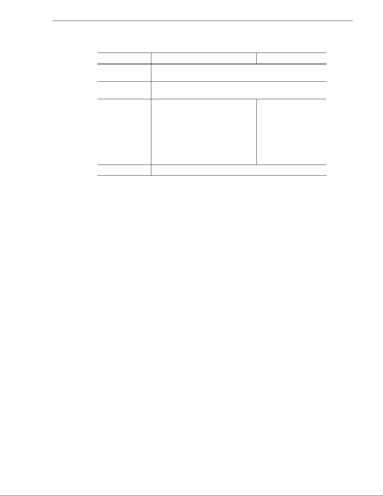
3. Open the disk module as illustrated in the following diagram.
40 K2 Lx0 RAID Instruction Manual July 31, 2008
Page 41

Installing disk module
1
Push the circled portion.
2
While pushing
the circled
portion, swing
the lever 40 degrees.
0
2
1
3
!
4. With both hands , hold the sides and underside of the disk modul e. Remove the disk
module as ill ustrated in th e following diagram.
Installing disk module
CAUTION: If the RAID chassis does not have the r edundant controller
option, when a replacement disk module is inserted there can be a 1.5
second disruption. Video record/play is not affected.
Before installing the disk module, make sure that you:
• Wait at least three minutes after removing the previous disk module.
July 31, 2008 K2 Lx0 RAID Instruction Manual 41
• Put a location label on the replacement disk drive, as appropriate for the slot into
which it is installed.
Page 42
Chapter 3 Servicing the K2 Lx0 RAID
0
2
1
3
Guide
Insert until the end of
the lever touches the
guide
To install a disk module:
1. Open the lever of the di sk module, a s demonstr ated i n “Remov ing a dis k module”
on page 40.
2. Insert the drive in the unit.
3. Insert the drive as shown in the following diagram.
4. Close the lever all the way.
3
The disk spins up automatically upon installation and, if the inserted disk is a
replacement for a failed drive in a bound LUN, data recovery begins.
Refer to “Interpreting controller status LEDs” on page 35 for disk module LED
status during re build. Aft erward, c heck dis k module s tatus u sing NetCe ntral o r the
Grass Vall ey Storage Utility.
42 K2 Lx0 RAID Instruction Manual July 31, 2008
Page 43

Replacing a RAID controller or expansion adapter
HOT
UNIT LABEL
Ejectors
!
Replacing a RAID controller or expansion adapter
Use the following instru ctions to replace a RAID con troller or expansi on adapte r. On
a chassis with two co ntrolle rs, the controll er or expa nsion adapt er should be repl aced
while the chassis is powered up (hot-swapped).
On a chassis with two controllers, if the controller microcode on the replacement
controller is not the same as that on the other currently installed controller, the
microcode on the repl acement con troller is au tomatically upgraded or d owngraded to
match that on the currently installed controller.
Removing a RAID controller or expansion adapter
To remove a RAID controller or expansion adapter:
1. If you are removing a redundant controller or an expansion adapter, identify the
module to be replaced using NetCentral or verify that the module’s Fault LED is
on. If you are removing an operational RAID controller, use the Grass Valley
Storage Utility to disab le the RAID c ontroller. If there is no re dundant controller,
power down the system.
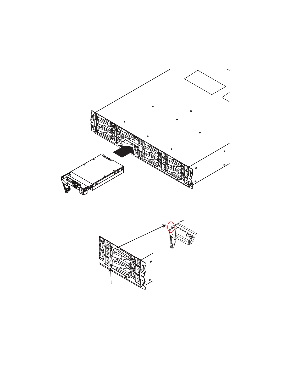
2. Disconnect all the cables.
NOTE: The cable to the SAS connectors has a blue tab labeled “Pres s.” Be sure to
press forward on the blue tab, rather than down.
3. Remove the power cable and the controller cable connected to the module. Note
where the cables conn ect to the module . The SAS cables for the K2 Lx0 Expansio n
Chassis are keyed so that one end can only be u sed with the DP-IN connecto r a nd
the other end can only be used with the DP-OUT connector.
4. Take an ejector of the module in each hand. Open them to the left and the right.
(The ejectors are lo cked at th e bottom.) The modu le comes out by freeing it on the
left and right. The diagram below shows the ejectors on a controller.
5. Holding the ejectors in both hands, pull horizontally approximately 4 inches.
6. Hold the module firmly in both hands and pull it all the way out.
CAUTION: The module might be hot.
July 31, 2008 K2 Lx0 RAID Instruction Manual 43
Page 44

Chapter 3 Servicing the K2 Lx0 RAID
NF
C
O
D
E LABEL
OPT
I
ON
LABEL
Power supply
Controller
or expansion
adapter
1
Finish inserting
2
the module in the chassis.
Close the ejectors, firmly pressing
the protruding portions of the ejectors.
Confirm that both ejectors are locked.
Installing a RAID controller or expansion adapter
To install a RAID controller or expansion adapter:
1. Install the module part way into the chassis, far enough in so that it is supported
physically by the housing.
2. Connect the cables.
3. Continuing instal ling the module in th e chassis, as shown in the following diagram.
HOT
Ejectors
UNIT LABEL
4. If inserting an expansion adapter on a system that has a redundant controller,
remove and reinsert the controller to start initialization. If inserting a controller or
expansion adapter on a sys tem that does not have a redundant contr oller, power up
the system.
5. Verify RAID controller initialization as displayed by the module’s Ready LED.
This process takes approximately three to eight minutes. Refer to “Interpreting
controller status LEDs” on page 35.
6. Check RAID controller status using NetCentral or the Grass Valley Storage Utility.
Replacing a power supply
• Use power cables that are shipped with the RAID unit.
• The K2 Lx0 RAID and K2 Lx0 Expansion Chassis have dual power supply
configurations so tha t they do not hal t if on e power su pply breaks down. Ev en if a
power supply is not functioning, the fan inside can draw power from the other
44 K2 Lx0 RAID Instruction Manual July 31, 2008
Page 45
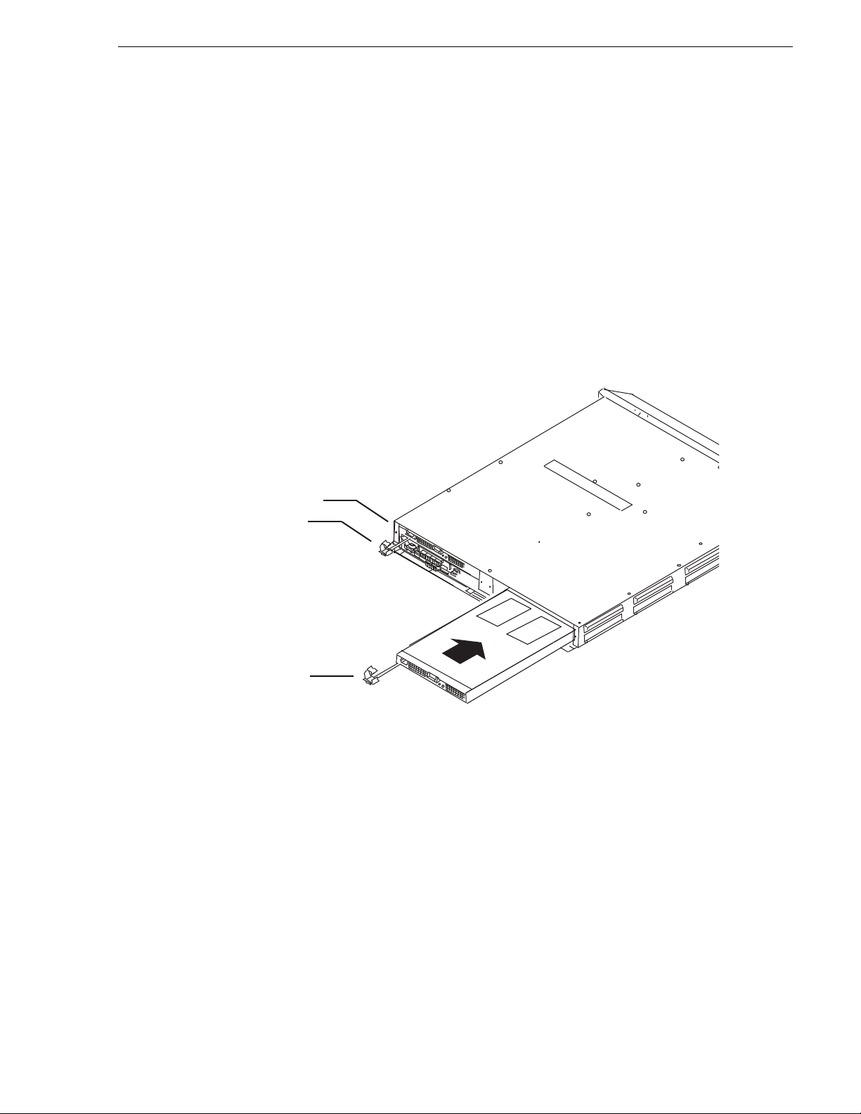
Replacing a battery
Power cable
clamp
N
F CODE
LABEL
OPTION LA
B
E
L
Power supply
Controller
or expansion
adapter
power supply, preventing overheating for a couple of minutes.
CAUTION: Make sure the cor rect type of replac ement p ower suppl y is
on hand and you are otherwise prepared to complete the procedure
within two minutes. If the time exceeds two minutes, the protective
feature of the RAID chassis triggers a shutdown sequence.
To replace the power supply:
1. Identify the faulty power supply by verifying that its Fault LED is on.
2. Unplug the power cable from the power supply.
3. Use the ejector to pull out the old power supply. Remove the power supply.
4. Push in the new power supply.
5. Reattach the power cable.
6. Secure the power cord by firmly fittin g the power c able clamp.
7. Check that the Good LED of the new power supply is on.
8. Monitor the status of the power supply using NetCentral.
Replacing a battery
Do not replace the internal battery unles s th e BBU Faul t LED i s bl i nkin g. (For more
information on controller LEDs, see “Interpreting controller status LEDs” on
page 35
To replace the battery, follow these steps:
1. Remove the controller from the chassis. For in formation on how to remov e the
July 31, 2008 K2 Lx0 RAID Instruction Manual 45
.)
Page 46
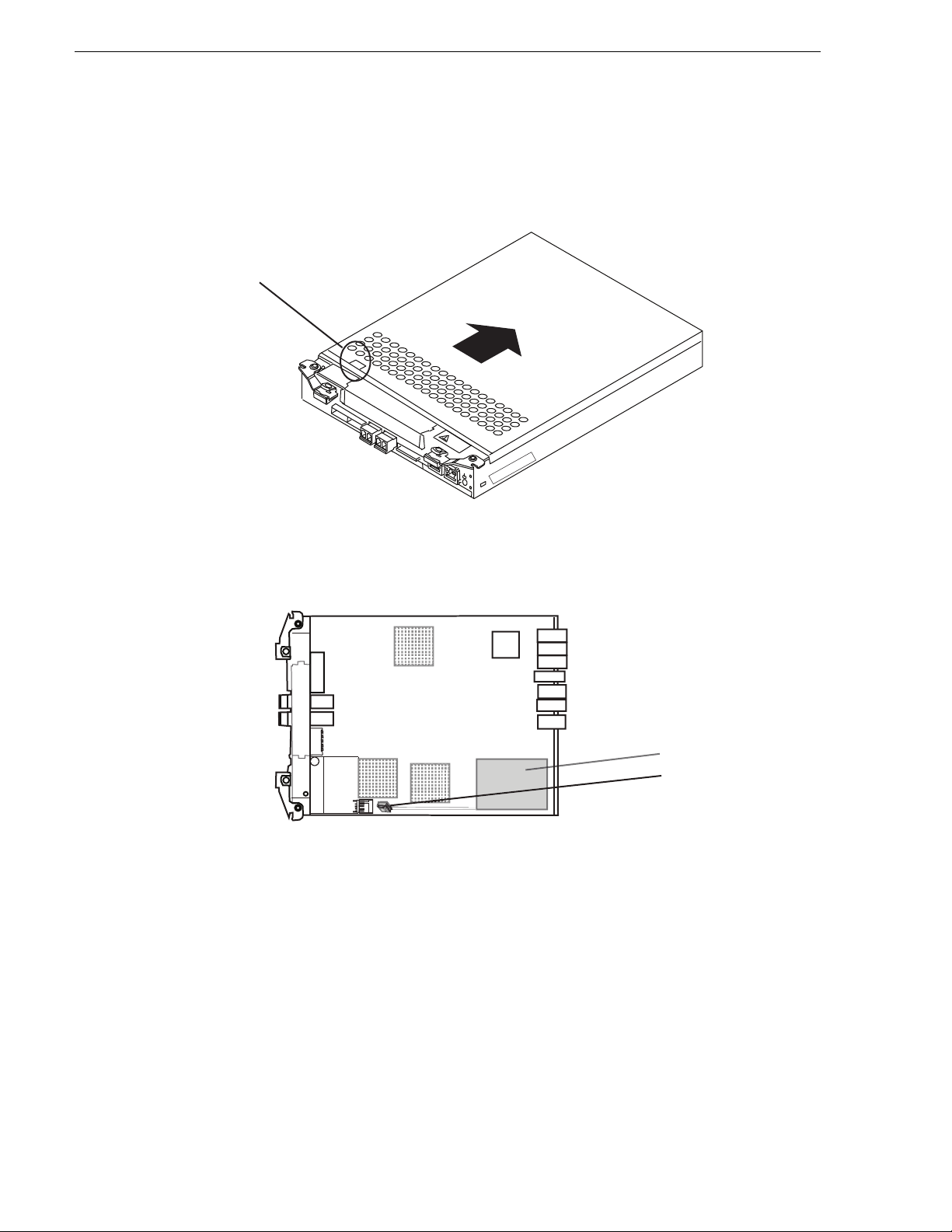
Chapter 3 Servicing the K2 Lx0 RAID
HOT
Lock
Battery
Battery plug
controller, see “Replacing a RAID controller or expansion adapter” on page 43.
2. Remove the cover by sliding it while pressing the lock, as indicated in following
diagram.
3. Holding the battery plug, unplug it from the controller. Do not pull while holding
on the cable.
4. Remove the battery from the controller.
5. Place the new battery in the controller, and firmly insert the plug into the battery
connector.
6. Replace the controller cover.
7. Return the controller to the chassis as described in “Installing a RAID controller or
expansion adapter” on page 44.
Adding expansion ports
If using an L30 or L30R K2 Lx0 RAID, additional expansion ports can be added to
the controller or controllers.
46 K2 Lx0 RAID Instruction Manual July 31, 2008
Page 47
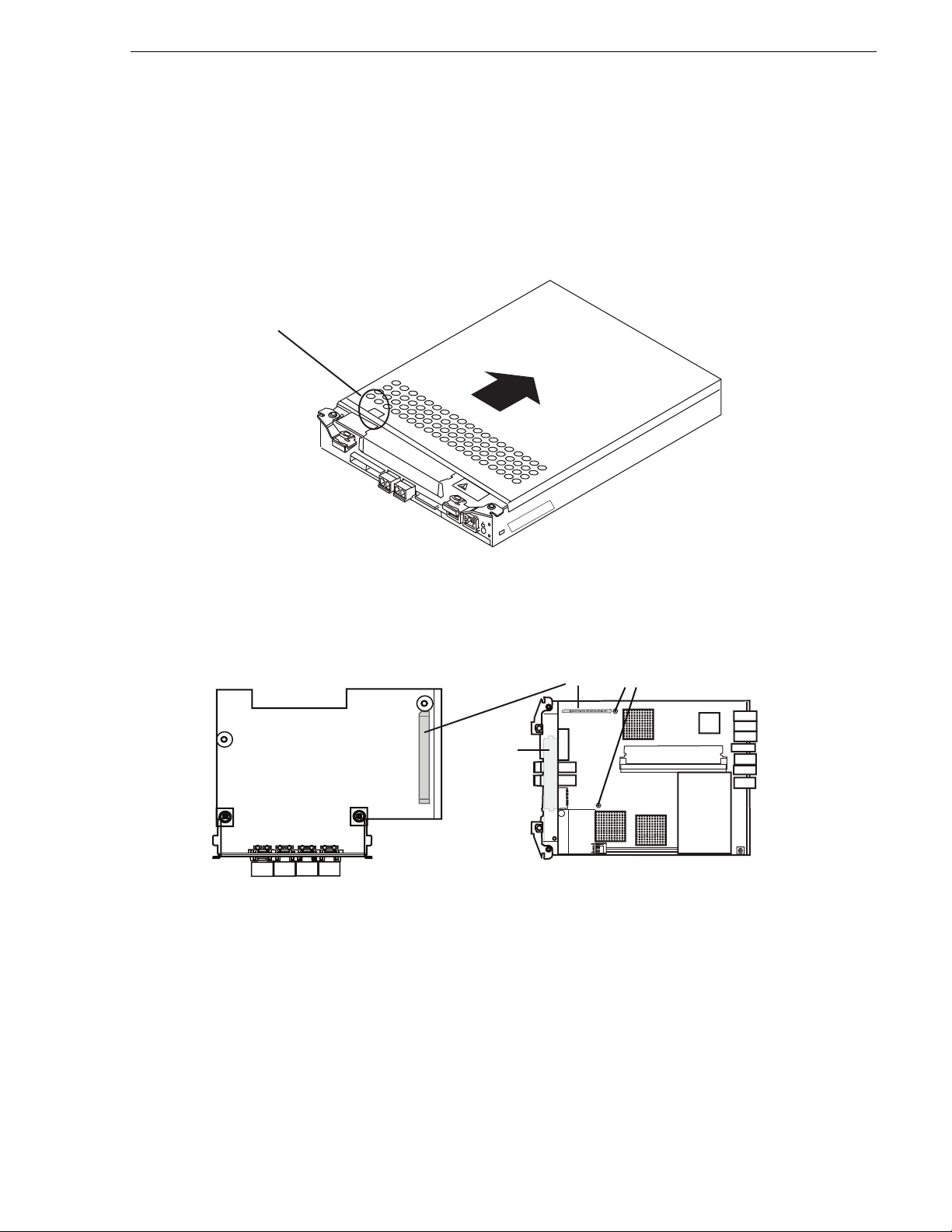
Adding expansion ports
HOT
Lock
To install additional expansion ports, follow these steps:
1. Remove the controller from the chassis. For in formation on how to remov e the
controller, see “Replacing a RAID controller or expansion adapter” on page 43.
2. Remove the cover by sliding it while pressing the lock, as indicated in following
diagram.
3. Remove the guard panel from the con troller, as indic ated in the follo wing diagram.
EXPANSION PORT
Guard
panel
CONTROLLER
Connector
Expansion port spacer
4. Insert the expansion port by matching the connector locations. Confirm that it is
firmly inserted and there is no play in the expansion port.
5. Secure with screws at the expansion port spacers.
6. Replace the controller cover.
7. Return the controller to the chassis as described in “Installing a RAID controller or
expansion adapter” on page 44.
July 31, 2008 K2 Lx0 RAID Instruction Manual 47
Page 48

Chapter 3 Servicing the K2 Lx0 RAID
48 K2 Lx0 RAID Instruction Manual July 31, 2008
Page 49
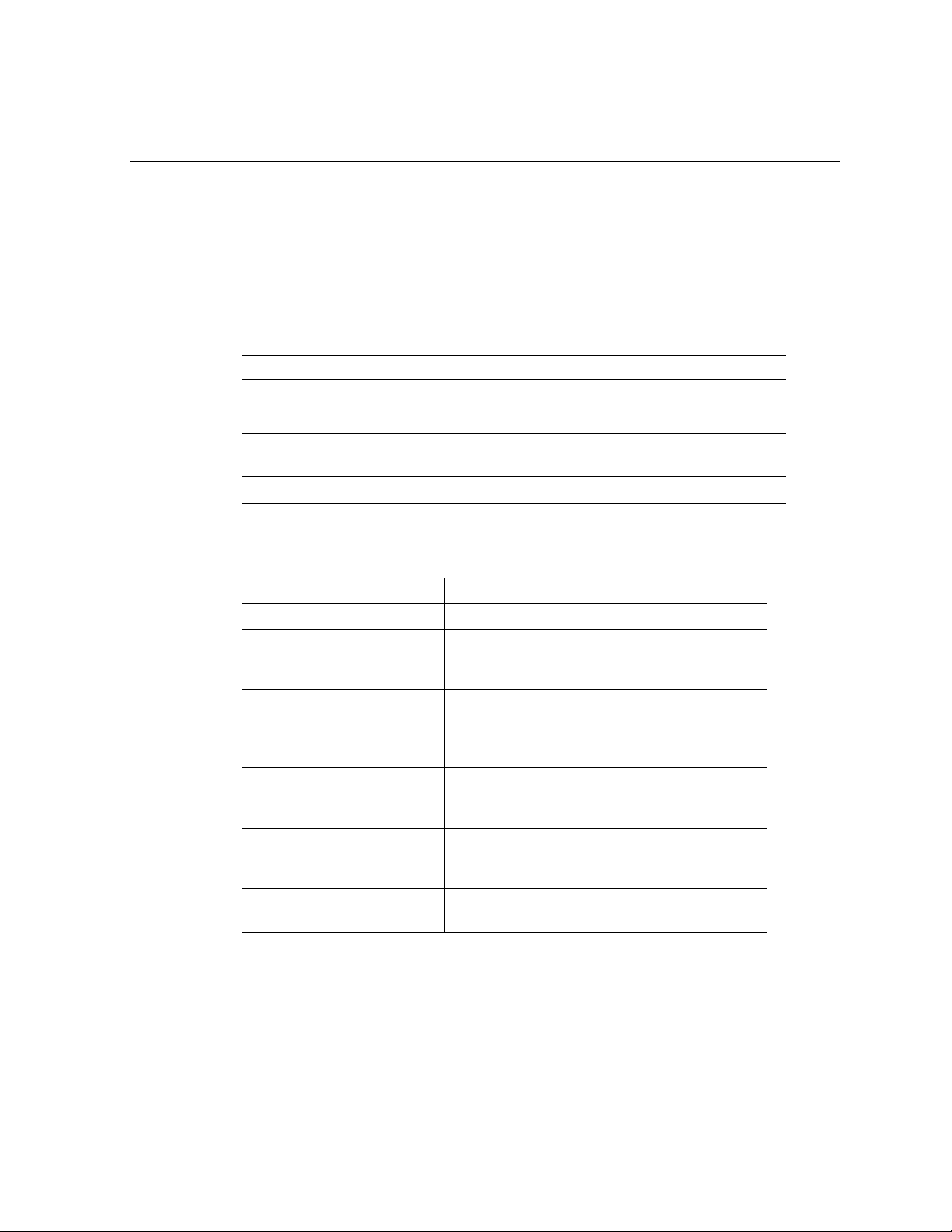
Chapter 4
K2 Lx0 RAID Technical Specifications and Operating Limits
Data handling specifications
Characteristic Specification
Host interface Fibre Channel
Data transfer rate 400 MB/s max
Number of host ports 2 ports pe r controller (L10, L20) 6 ports (Optional, an
additional 4 ports, L30)
Cache memory 1 GB (L10) 2 GB (20), 4 GB (L30)
AC power requirements
Item Measurement
Input voltage 100 to 240 VAC ±10% (x2), 50/60 Hz
Power consumption
Power supply
Maximum power consumption
Basic Chassis
L10, L10R, L20, L20R
configurations
Maximum power consumption
Basic Chassis
L30, L30R configurations
Maximum power consumption
Expansion Chassis
All configurations
a
Power supply:
Basic cabinet: 2118 B TU/ W
Expansion cabinet: 1470 BTU/W
a.
SAS
AC: 610VA/590W
DC: 580W
a.
SAS
AC: 640VA/620W
DC: 610W
a.
SAS
AC: 610VA/590W
DC: 580W
SATA
AC: 550VA/530W
DC: 520W
SATA
AC: 570VA/550W
DC: 540W
SATA
AC: 550VA/530W
DC: 520W
Labeling according to the energy
saving act
a.
For UPS choice, a safety allowance of 30% of the power consumption is necessary.
Category: i
Energy consumption efficiency: 0.10
If one of the two p ower supplies fa ils, the re maining supply and cord must suppo rt the
full load. Your rackmount ca binet must include AC power distrib ution that can handle
these values.
July 31, 2008 K2 Lx0 RAID Instruction Manual 49
Page 50

Chapter 4 K2 Lx0 RAID Technical Specifications and Operating Limits
Size and weight
Item Measurement
Cabinet
dimensions
(excluding
bezel)
Weight Basic cabinet: 31 kg or lighter
Basic cabinet: 445mm W x 54 0mm D x 86.5mm H
(same for primary chassis and expansion chassis)
Expansion cabinet: 29 kg or lighter
Cable lengths
It is recommended that you use the cables shipped with your K2 Lx0 RAID when
making connections. Host cables must meet the appropriate standards for 4-Gb/s
HBA compliance (maximum c able len gth 150m). SAS cables are used to connec t the
RAID chassis with the expansion chassis.
Environmental limits
The system includes two temperature level sensors used to issue auto-warning and
auto-shutdown in case the over temperature limit is reached.
Characteristic Specification
Ambient tempera t u r e Operating: 5°C to 40° C
Halting: -10°C to 60°C
Relative humidity
(without condens a tio n)
Allowable vibration l evel Operating: 0.25 G or less
Operating: 10% to 80%
Halting: 5% to 80%
Halting: 0.5 G or less
Life expectancies of components
Item Measurement
Battery backup unit 5 years
Fan (power supply) 5.7 years
50 K2 Lx0 RAID Instruction Manual July 31, 2008
Page 51

Glossary
The terms and definitions listed below are related to the storage system described in
this manual. Understanding them will aid your understanding of the storage system.
bind
In the context of a disk-array storage system, the procedure by which you
hardware-format one or more disk modules into one logical unit. Grass Valley
Storage Utility lets you bind disks into a logica l unit reco gni zed by the Windows
operating system, the media file system, and other software. Storage Utility labels this
group of disks a rank.
BTU (British Thermal Unit)
A standard measure of a device’s heat output.
cache
See storage-system caching.
direct-connect storage
K2 Media Client models access their own external media storage drives that are
contained in a Lx0 RAID chassis. Referred to as stand-alone systems. See internal
storage, s hared stora ge.
disk-drive module
Another name for disk module.
disk unit
A short name for physical disk unit.
disk module
A self-cont ained disk drive that slid es into one of the slots in th e front of the s torage
system. It consists of the carrier a ssembly, which holds the disk dri ve and the
regulator board. Also called disk-drive module.
EMI (electromagnetic interference)
Electronic radiation emitted by an electrical device. The levels of EMI are strictly
controlled for da ta p rocessing equipment. The EMI st andards are explaine d af te r t h e
Notice page near the beginning of the manual.
ESD (electrostatic discharge)
The discharge of an accumulated electrical charge (static). This can severely damage
delicate electron ic circuits.
field-replaceable unit
See FRU (field-replaceable unit).
FRU (field-replaceable unit)
A hardware assembly that can be replaced on site, instead of at the point of
manufacture.
July 31, 2008 K2 Lx0 RAID Instruction Manual 51
Page 52

Glossary
hot repair
See replace under power.
internal storage
K2 Media Client models with intern al storage acce ss their own int ernal media sto rage
drives. Referred to as a stand-alone system. See also direct-connect storage, shared
storage.
K2 Lx0 RAID Storage
A storage s ystem that includes a chassis, up to 12 disk modules, one or two RAID
controllers, and two power supplies. A K2 Lx0 can support up to eleven K2 Lx0
Expansio n Chassis (with up to 12 disk modul es each) in addition to i ts own 12 disk
modules.
K2 Lx0 Expansion Chassis
A storage system that incl udes a chassis, up to 12 disk modules, two expans ion adapters,
and two power supplies.
K2 Media Client
A Broadcast Enterprise S erver that incorporates IT server pl atform and st orage
technologies. The K2 Media Client can be used with internal, direct-connect, or
shared storage.
power supply
An essential element of the storage-syst em power supply. A sto rage system ca n have
two power supplies. With two, it can sur vive failure of one supply . You can replace a
power supply under power without interrupting applications.
rank
See bind.
replace under power
The storage system provides replace un der power ca pability, a llowing you to replace ,
for example, a disk module or a power supply module without powering down the
storage system. Applications continue while you replace the failed module.
SCSI (small computer system interface)
A well-known protocol and standard for connecting computers and peripheral
devices.
SES (SCSI enclosure services)
A functional subset of SCSI III commands that allow a server to communicate with
storage enclosures using their disk modules.
server
In the context o f s torage systems, a p roc ess o r th at runs an operati ng sys tem and uses
a disk-array storage system for data storage and retrieval.
52 K2 Lx0 RAID Instruction Manual July 31, 2008
Page 53

SFF
Small Form Factor Comm ittee
shared storage
K2 Media Client models with shared storage access RAID protected media storage
drives that are part of a K2 Storage System (SAN). The K2 Storage System
incorporates one or more RAID chassis, such as K2 Lx0 RAID. See also
direct-connect storage, internal storage.
storage chassis
A storage device that includes a chassis, up to 12 disk modules, one or two RAID
controllers, one LAN card, and two power supplies.
July 31, 2008 K2 Lx0 RAID Instruction Manual 53
Page 54

Glossary
54 K2 Lx0 RAID Instruction Manual July 31, 2008
Page 55

Index
A
AC power
current draw 49
overview 21
B
battery
life expectancy 50
replacement 6
Battery Backup Unit 17
battery, replacing 45
binding disk modules 22
blinking disk module LEDs 32
C
cabling
max lengths 21
requirements 21
Canadian EMC Notice of Compliance 7
certifications and compliances 7
chassis
description 17
circuit boards
description 18
colors, disk module LEDs 32
components 16
See FRUs (field replaceable units)
configurations 16
controller
replacing 43
status LEDs 35
D
disk module
description 19
disk module LED colors 32
disk module LED displays, interpreting 32
identification 19
installing 41
removing 40
description 18
replacing 43
expansion adapter, replacing 43
expansion ports, adding 46
F
fan
life expectancy 50
FCC Emission Control and Limits 7
field replaceable units (see FRUs)
fire hazard 5
flashing disk module LEDs 32
FRUs (field-replaceable units)
disk module
description 19
replacing 40
expansion adapter
description 18
replacing 44
power supply
description 19
replacing 44
RAID Controller
description 17
replacing 43
G
grounding
safety 5
H
high availability features 16
HPE, adding 46
I
injury precautions 5
installing
disk module 41
K2 Lx0 RAID 22
K
E
electric shock 5
EN55022 Class A Warning 7
expansion adapter
July 31, 2008 K2 Lx0 RAID Instruction Manual 55
K2 Level 2 RAID Expansion
installing in rack 24
K2 Lx0 RAID
Page 56

Index
components 16
configurations 16
defined 16
disk module description 19
high availability featu res 16
installation requirements 21
monitoring status 31
operating limits 50
power supply, description 19
powering down 29
rear panel view 17
requirements
cabling 21
operating 50
, 18
L
Laser 8
Laser Compliance 8
LEDs
disk modules 32
rear panel 35
life expectancies of components 50
, 38, 39
battery 45
controller 43
disk module 40
expansion adapter 43
power supply 44
S
safety ground 28
safety summary 5
safety terms and symbols 6
service safety summary 7
site requirements 21
size and weight 50
SNMP monitoring 31
standby switch 44
status
monitoring K2 Lx0 RAID 31
storage utility 22
V
ventilation 5
voltage, K2 Lx0 RAID requirements 49
N
NetCentral 31
P
packaging 22
power
cord 28
outlet 28
power supply
description 19
LEDs 39
replacing 44
powering-up 28
product damage precautions 5
R
rack mounting 22
RAID configuration 22
RAID Controller
description 17
replacing 43
status LEDs 35
remote monitoring 31
replacing
W
web site, for Thomson Grass Valley 12
56 K2 Lx0 RAID Instruction Manual July 31, 2008
 Loading...