

Page 1
K2 Level 2 RAID
FIBRE CHANNEL STORAGE
Instruction Manual
071-8462-01
SEPTEMBER 2006
Page 2

Copyright Copyright © 2006 Grass Valley, Inc. All rights reserved. Printed in the United States of America.
This document may not be copied in whole or in part, or otherwise r eproduced except as
specifically permitted under U.S. copyright law, without the prior written consent of Grass
Valley, Inc., P.O. Box 59900, Nevada City, California 95959-7900
This product may be covered by one or more U.S. and foreign patents.
Trademarks Grass Valley, K2, Turbo, M-Series, Profile, Profile XP, NewsBrowse, NewsEdit, NewsQ,
NewsShare, NewsQ Pro, Aurora, and Media Manager ar e either registered trademarks or
trademarks of Grass Valley, Inc. in the United States and/or other countries. Other trademarks
used in this document are either registered trademarks or trademarks of the manufacturers or
vendors of the associated products. Grass Valley, Inc. products are covered by U.S. and
foreign patents, issued and pending. Additional information regarding Grass Valley, Inc.
trademarks and other proprietary rights may be found at www.thomsongrassvalley.com.
Disclaimer Product options and specifications subject to change without notice. The information in this
manual is furnished for informational use only, is subject to change without notice, and should
not be construed as a commitment by Grass Valley, Inc. Grass Valley, Inc. assumes no
responsibility or liability for any errors or inacc uracies that may appear in this publication.
U.S. Government
Restricted Rights
Legend
Use, duplication, or disclosure by the United States Government is subject to restrictions as set
forth in subparagraph (c)(1)(ii) of the Rights in Technical Data and Computer Software clause
at DFARS 252.277-7013 or in subparagraph c(1) and (2) of the Commercial Computer
Software Restricted Rights clause at FAR 52.227-19, as applicable. Manufacturer is Grass
Valley, Inc., P.O. Box 59900, Nevada City, California 95959-7900 U.S.A.
Revision Status
Rev Date Description
November 23,
2005
September 8,
2006
Initial release of the K2 Level 2 RAID Fibre Channel Storage
Instruction Manual. Part number 071-8462-00
Corrected controller DIP switch settings. Part number —
071-8462-01
2 Level 2 RAID Instruction Manual September 8, 2006
Page 3

Contents
Safety Summaries..............................................................................................5
Preface..................................................................................................................11
Chapter 1 About the K2 Level 2 RAID storage
K2 Level 2 RAID features........................................................................................17
K2 Level 2 RAID features...................................................................................18
Capacity and redundancy...................................................................................18
K2 Level 2 RAID components.................................................................................18
Chassis...............................................................................................................19
Midplane.............................................................................................................20
Disk modules......................................................................................................20
K2 Level 2 RAID Circuit board modules.............................................................21
K2 Level 2 RAID RAID Storage Chassis circuit board modules....................21
K2 Level 2 RAID Expansion Chassis circuit board modules .........................22
Power supplies...................................................................................................23
Configurations.........................................................................................................24
Chapter 2 K2 Level 2 RAID Installation Information
Installation requirements .........................................................................................25
Site requirements ...............................................................................................25
Power.............................................................................................................25
Cooling...........................................................................................................25
Controller configuration requirements ................................................................26
Addressing requirements....................................................................................27
FC-AL address ID..........................................................................................27
Chassis address setting requirement ............................................................28
Expansion chassis diagnostic switch setting requirement.............................29
Cabling requirements.........................................................................................30
Binding disk modules into groups.............................................. .........................30
Installing a K2 Level 2 RAID Storage in an equipment rack....................................31
Unpacking the chassis............................. ...... ................................. ...... ...... ........31
Installing the rack mounts...................................................................................31
Inserting the K2 Level 2 RAID Storage chassis in the rack................................33
K2 Level 2 RAID Storage power-up and initialization..............................................36
Connecting electrical cables................................................ ...... ..... ....................36
Powering-up the K2 Level 2 RAID Storage system............................................36
K2 Level 2 RAID Storage power-down....................................................................37
Battery Backup........................................................................................................37
Chapter 3 Servicing the K2 Level 2 RAID
Maintenance procedures using Storage Utility........................................................39
Monitoring K2 Level 2 RAID status using NetCentral..............................................39
Interpreting front panel LEDs ..................................................................................41
Interpreting disk module LEDs............................................................ ...... ...... ..... ...42
Interpreting controller status LEDs..........................................................................43
Interpreting expansion adapter sta tus LEDs........................................................ ...45
Interpreting LAN card status LEDs............................................................ ...... ........46
Interpreting power supply status LEDs....................................................................47
Removing and installing disk modules....................................................................47
Moving disk modules..........................................................................................47
Removing a disk module ....................................................................................48
Installing disk module.........................................................................................49
Replacing a RAID controller or expansion adapter .................................................50
Removing a RAID controller or expansion adapter ............................................50
September 8, 2006 Level 2 RAID Instruction Manual 3
Page 4

Contents
Installing a RAID controller or expansion adapter..............................................51
Replacing the LAN card.......................................................................................... 53
Replacing a power supply.......................................................................................56
Chapter 4 K2 Level 2 RAID Technical Specifications and Operating Limits
AC power requirements .......................................................................................... 61
Size and weight.......................................................................................................61
Cable lengths.......................................................................................................... 61
Environmental limits................................................................................................ 62
Life expectancies of components............................................................................ 62
Glossary............................................................................................................... 63
Index......................................................................................................................67
4 Level 2 RAID Instruction Manual September 8, 2006
Page 5

Safety Summaries
General Safety Summary
Review the following saf ety precautions to avoid injury and prevent damage
to this product or any products connected to it.
Only qualified personnel should perform service procedures.
While using this pr oduc t, you may need to acce ss oth er par ts o f the syste m.
Read the General Safety summary in other syst em manuals for warnings and
cautions related to operating the system.
Injury Precautions
Use Proper Power Cord
To avoid fire hazard, use only the power cord specified for this product.
Ground the Product
This product is grounded through the grounding conductor of the power
cord. To avoid electric shock, the grounding conductor must be connected
to earth ground. Before maki ng connections to the input or outpu t terminals
of the product, ensure that the product is properly grounded.
Do Not Operate Without Covers
To avoid electric shock or fire hazard, do not operate this product with
covers or panels removed.
Do Not operate in Wet/Damp Conditions
To avoid electric shock, do not operate this product in wet or damp
conditions.
Do Not Operate in an Explosive Atmosphere
To avoid injury or fire hazard, do not operate this product in an explosive
atmosphere.
Avoid Exposed Circuitry
To avoid injury, remove jewelr y such as ring s, wa tc hes , and othe r meta ll ic
objects. Do not touch ex posed conn ectio ns and compone nts when power is
present.
Product Damage Precautions
Use Proper Power Source
Do not operate this product f rom a power sour ce that applie s more than the
voltage specified.
Provide Proper Ventilation
To prevent product overheating, provide proper ventilation.
September 8, 2006 Level 2 RAID Instruction Manual 5
Page 6
Safety Summaries
Do Not Operate With Suspected Failures
If you suspect there is da mage to this product, have it in spected by q ualified
service personnel.
Battery Replacement
To avoid damage, replace only with the same or equivalent type
recommended by the circuit board manufacturer. Dispose of used battery
according to the circuit board manufacturer’s instructions.
Safety Terms and Symbols
Terms in This Manual
These terms may appear in this manual:
!
!
Terms on the Product
Symbols on the Product
WARNING: Warning statements identify conditions or practices that can
result in personal injury or loss of life .
CAUTION: Caution statements identify conditions or practices that may
result in damage to equipment or other property, or which may cause
equipment crucial to your business environment to become temporarily
non-operational.
These terms may appear on the product:
DANGER indicates a personal injury hazard immedi ately access ible as one
reads the ma rking.
WARNING indicates a personal injury hazard not immediately accessible
as you read the marking.
CAUTION indicates a hazard to property including the product.
The following symbols may appear on the product:
DANGER high voltage
Protective ground (earth) terminal
!
6 Level 2 RAID Instruction Manual September 8, 2006
ATTENTION – refer to manual
Page 7

Service Safety Summary
!
Do Not Service Alone
Disconnect Power
Use Care When Servicing With Power On
WARNING: The service instructions in this manual are intended for
use by qualified service personnel only. To avoid personal injury, do
not perform any servic ing unless you are qualified t o do so. Refer to al l
safety summaries before performing service.
Do not perform interna l service or adj ustment of this pro duct unless anothe r
person capable of rendering first aid and resuscitation is present.
To avoid electric shock, discon nect the main power by means of the power
cord or, if provided, the power switch.
Dangerous voltages or cur rents may exist in t his product. Discon nect power
and remove battery (if applicable) before removing protective panels,
soldering, or replacing components.
To avoid electric shock, do not touch exposed connections.
Certifications and Compliances
Canadian Certified Power Cords
Canadian approval includes the products and power cords appropriate for
use in the North America power network. All other power cords supplied are
approved for the country of use.
FCC Emission Control
This equipment has been tested and found to comply with the limits for a
Class A digital device, pursuant to Part 15 of the FCC Rules. These limits
are designed to provide reasonable protection against harmful interference
when the equipment is operated in a commercial environment. This
equipment generates, uses, and can radiate radio frequency energy and, if
not installed and use d in accordance with th e instruction ma nual, may cause
harmful interfere nce to radio communication s. Operation of thi s equipment
in a residential area is likely to cause harmful interference in which case the
user will be required to cor rect the interference at his own expense. Changes
or modifications not expressly approved by Grass Valley can affect
emission compliance a nd could void the user’s authority to operate this
equipment.
September 8, 2006 Level 2 RAID Instruction Manual 7
Page 8

Safety Summaries
Canadian EMC Notice of Compliance
EN55103 1/2
Class A Warning
FCC Emission Limits
This digital apparatus does not exceed the Class A limits for radio noise
emissions from digital apparatus set out in the Radio Interference
Regulations of the Canadian Department of Communications.
Le présent appareil numérique n’émet pas de bruits radioélectriques
dépassant les limites applicables aux appareils numériques de la classe A
préscrites dans le Règlement sur le brouillage radioélectrique édicté par le
ministère des Communications du Canada.
This product has been evaluated for Electromagnetic Compatibility under
the EN 55103-1/2 standards for Emissions and Immunity and meets the
requiremen ts for E4 environment.
This product complies with Class A (E4 environment). In a domestic
environment this product may cause radio interference in which case the
user may be required to take adequate measures.
This device complies with Part 15 of the FCC Rules. Operation is subject to
the following two conditions: (1) This device may not cause harmful
interference, and (2) this device must accept any interference re ceived,
including interference that may cause undesirable operation.
Laser Compliance
Laser Safety Requirements
The device used in thi s product is a Class 1 certi fied laser product. Opera ting
this product outsi de spe cifications or altering its original design may result
in hazardous radiati on exposure, and may be consi dered an act of modifyi ng
or new manufacturing o f a laser product under U.S. regula tions contained i n
21CFR Chapter 1, subchapter J or CENELEC regulations in HD 482 S1.
People performing such an act are re quired by law to re certify and reid entify
this product in accordance with provisions of 21CFR subchapter J for
distribution within th e U.S.A., and in accordance with CENELEC HD 482
S1 for distr i bution within countries using the IEC 825 sta ndard.
Laser Safety
Laser safety in the United States is regulated by the Center for Devices and
Radiological Health ( CDRH). The la ser safety regulations a re publ is hed i n
the “Laser Product Performance Standard,” Code of Federal Regulation
(CFR), Title 21, Subchapter J.
The International Electrotechnical Commission (IEC) Standard 825,
“Radiation of Laser Produ cts, Equipmen t Classific ation, Requi rements and
User’s Guide,” gov erns laser products outside the Unit ed States. Europe and
member nations of the European Free Trade Association fall under the
jurisdiction of the Comité Européen de Normalization Electrotechnique
(CENELEC).
8 Level 2 RAID Instruction Manual September 8, 2006
Page 9
Safety Certification
This product has been evaluated and meets the following Safety
Certificat ion Standards:
Standard Designed/tested for compliance with:
UL1950 Safety of Information Technology Equipment,
IEC 950 Safety of Information Technology Equipment,
CAN/CSA C22.2,
No. 950-95
EN60950 Safety of Information Technology Equipment,
Disposing of your used product
In the European Union — EU-wide l egislation as implemen ted in each
member state requires that used electrical and electronic products carrying
the mark at left must be disposed of separately from normal household
waste. The equipment with this mark may include electrical accessories
(e.g. memory cards). When you dispos e of such produc ts, please follow the
agreements made between you and Grass Valley. Th e mark on the elect rical
and electronic produc ts only applies to the c urrent European Union Membe r
States. This statement is in compliance with European Commission
Directive 2002/96/EC Waste Electrical and Electronic Equipment.
including Electrical Business Equipment (Third
edition).
including Electrical Business Equipment
(Second edition, 1991).
Safety of Information Technology Equipment,
including Electrical Business Equipment.
including Electrical Business Equipment 1992.
Outside the European Un ion — If you wish to dispo se of used electric al and
electronic produc ts outside o f the European Un ion, please c ontact your local
authority and ask for the correct method of disposal.
September 8, 2006 Level 2 RAID Instruction Manual 9
Page 10

Safety Summaries
10 Level 2 RAID Instruction Manual September 8, 2006
Page 11
Preface
About this manual
The K2 Level 2 RAID Storage Chassis provides RAID protected storage for the K2
Storage System. If you are responsible for installing and servicing the K2 Level 2
RAID storage, you should read this manual.
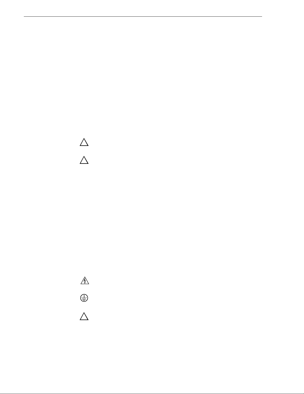
Using the K2 Documentation Set
The following illustration shows the recommended order in which to reference the
documentation.
Path for the installer of K2 Media Client models with internal storage
Grass Valley
K2 Manual
ιεσ
ιεσ
ιεσ
ιεσ
ιεσ
ιεσ
Γρασσ ςαλλεψ Γρουπ
Φαμιλψ οφ ΞΠ Σερ
Φαμιλψ οφ ΞΠ Σερ
Φαμιλψ οφ ΞΠ Σερ
Φαμιλψ οφ ΞΠ Σερ
Φαμιλψ οφ ΞΠ Σερ
Φαμιλψ οφ ΞΠ Σερ
K2 Media Client
Release Notes
Contains the latest information
about the hardware and
software shipped with the
system. Packaged with K2
Media Client.
t
r
t
a
t
n
e
S
m
k
u
c
ui
oc
d
Q
u
o
2
is
u
h
K
sy
o
T
p
y
l
u
e
o
h
ps
l
y
e
h
ps
l
e
h
Quick Start Guide
Contains the essential steps for
installing the K2 Media Client.
SD-only and HD/SD models each
have their own version, packaged
with the K2 Media Client.
K2 Media Client
System Guide*
Contains the product
specifications and
step-by-step instructions for
modifying system settings.
Documentation
CD
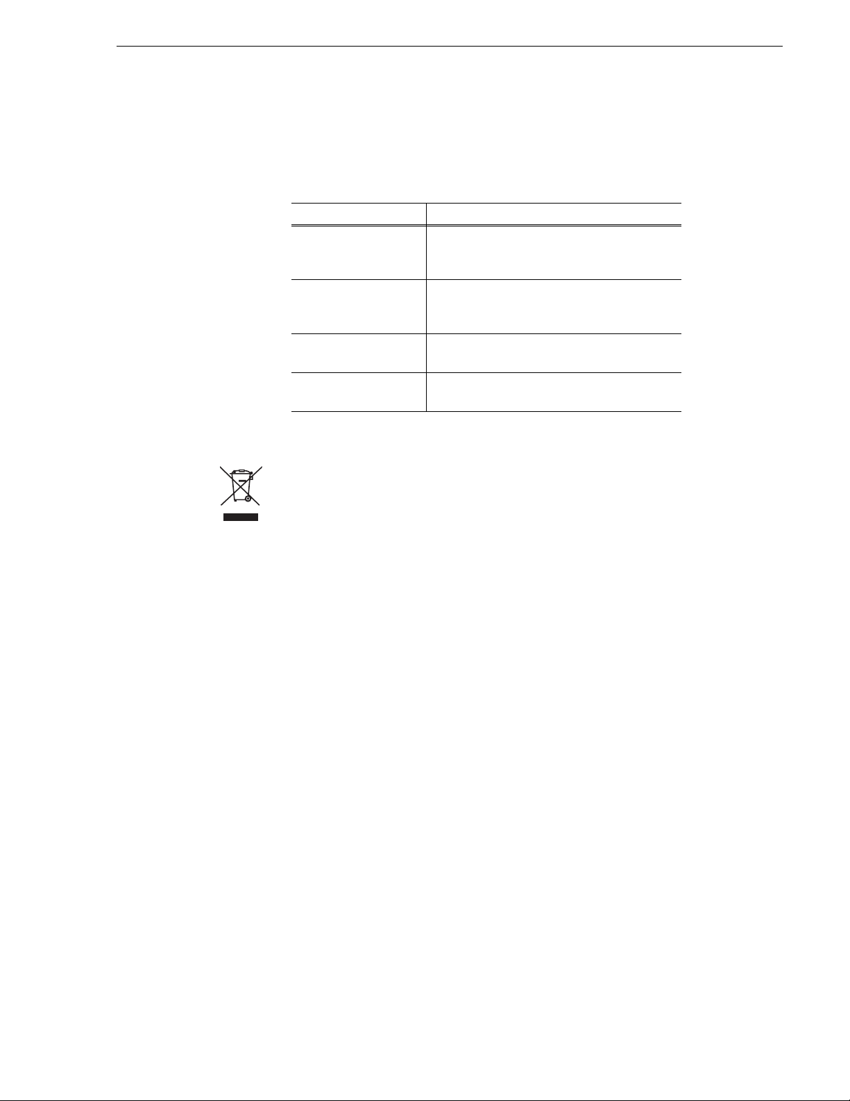
Path for the installer of the K2 Storage System with connected K2 Media Clients
ουπ
ουπ
ιεσ
ιεσ
ιεσ
ιεσ
ιεσ
ιεσ
ιεσ
ιεσ
ιεσ
ιεσ
ιεσ
Γρασσ ςαλλεψ Γρ
Φαμιλψ οφ ΞΠ Σερ
ιεσ
Φαμιλψ οφ ΞΠ Σερ
Γρασσ ςαλλεψ Γρ
Φαμιλψ οφ ΞΠ Σερ
Φαμιλψ οφ ΞΠ Σερ
Φαμιλψ οφ ΞΠ Σερ
Φαμιλψ οφ ΞΠ Σερ
Φαμιλψ οφ ΞΠ Σερ
Φαμιλψ οφ ΞΠ Σερ
Φαμιλψ οφ ΞΠ Σερ
Φαμιλψ οφ ΞΠ Σερ
Φαμιλψ οφ ΞΠ Σερ
Φαμιλψ οφ ΞΠ Σερ
K2 Media Client and
K2 Storage System**
Release Notes
Contains the latest
information about the
hardware and software
shipped with the system.
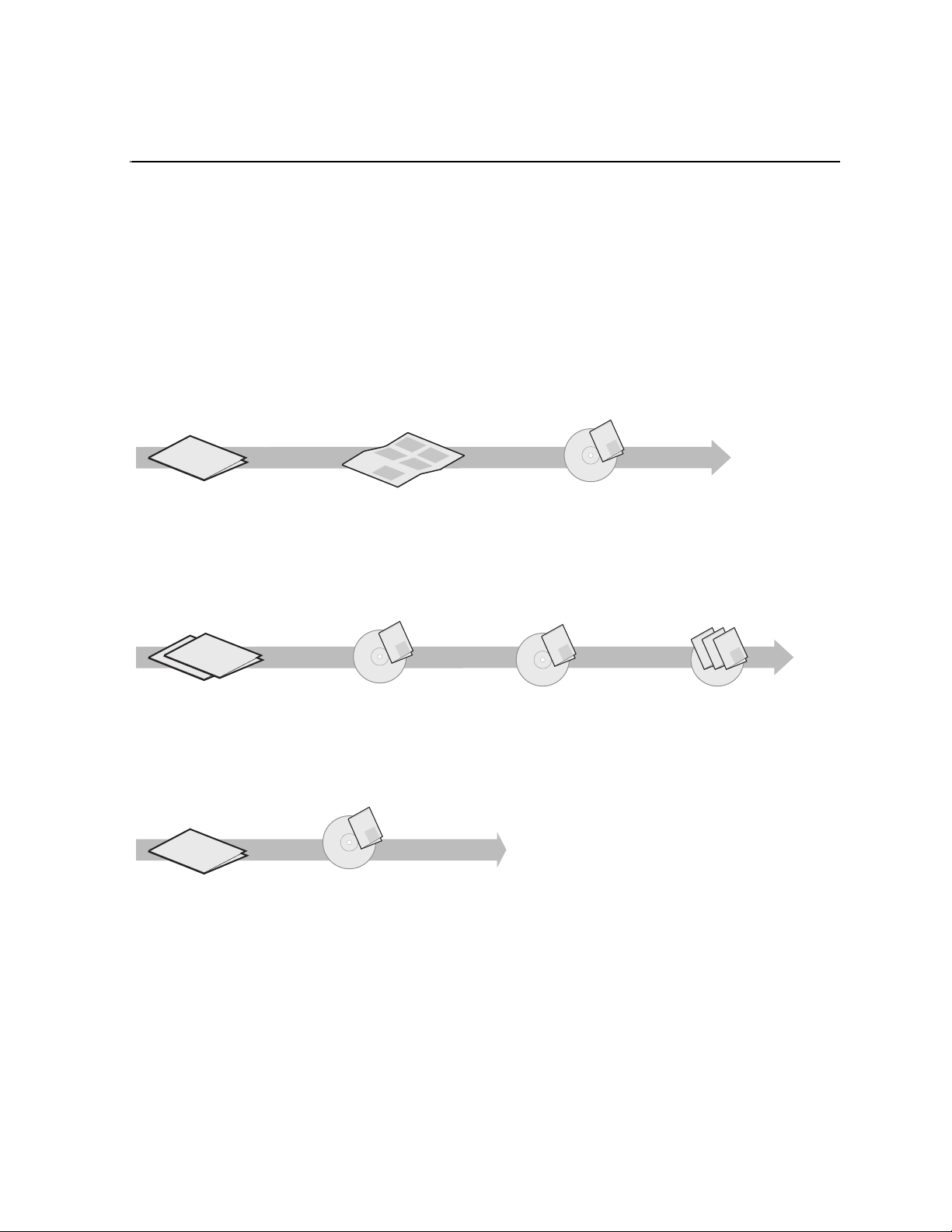
ath for the operator
ουπ
ιεσ
ιεσ
ιεσ
ιεσ
ιεσ
ιεσ
Γρασσ ςαλλεψ Γρ
Φαμιλψ οφ ΞΠ Σερ
Φαμιλψ οφ ΞΠ Σερ
Φαμιλψ οφ ΞΠ Σερ
Φαμιλψ οφ ΞΠ Σερ
Φαμιλψ οφ ΞΠ Σερ
Φαμιλψ οφ ΞΠ Σερ
K2 Media Client
Release Notes
Contains the latest
information about the
hardware and software
shipped with the system.
Grass Valley
K2 Manual
Documentation
CD
K2 Storage System
Instruction Manual*
Contains instructions for installing
and configuring K2 Storage
(external) with your K2 Media
Client and K2 Media Server or
Level 1 device.
Grass Valley
K2 Manual
Documentation
CD
K2 Media Client
User Manual*
Contains information for using
the user interface to record,
play and manage clips and to
configure channels.
Find the K2 Documentation CD packaged with K2 Media
*
Clients and with K2 RAID Storage devices, primary chassis.
Find the K2 Storage System Release Notes packaged with
**
K2 RAID Storage devices, primary chassis.
Grass Valley
K2 Manual
Documentation
CD
K2 Media Client
System Guide*
Contains the product
specifications and
step-by-step instructions for
modifying system settings
Grass Valley
Grass Valley
K2 Manual
Documentation
CD
Other Manuals*
These manuals include:
-
Quick Start Guide
-
User Manual
- Service Manual
- RAID Storage manuals
Documentation descriptions
Use the following descriptions to choose the other documentation you need as you
install, operate, and maintain your system.
Grass Valley
K2 Manual
K2 Manual
September 8, 2006 Level 2 RAID Instruction Manual 11
Page 12

Preface
K2 Storage System Release Notes
The release notes contain the latest information about the software shipped on your
system. Th e information in this document includes softw are upgrade instructi ons,
software specificat ions and require ments, feature cha nges from the previo us releases,
and any known problems. Because release notes contain the latest information, they
are printed out rather tha n included in the Documentati on CD-ROM. You can find the
release notes packaged with the RAID storage chassis.
Documentation CD-ROM
Except for the release notes, the full set of support documentation, including this
manual, is available on the Documentation CD-ROM that you receive with your K2
Media Client. You can find the Documentation CD-ROM packaged with the RAID
storage chassis.
The Documentation CD-ROM includes the following:
•
K2 Storage System Instruction Manual — Contains installation, configuration, and
maintenance procedures for shared storage options.
Level 1 and RAID Instruction Manuals — There is an Instruction Manual for the
•
Level 1 device each type of RAI D storag e device that ca n be a p art of a K2 Med ia
Client. These manuals con tain procedures for co nfiguring and serv icing the device.
K2 Media Client System Guide — Contains the product specifications and
•
step-by-step instructions for mo difying system settings. Includes instructions for
adding a K2 Media Client to the K2 Storage System.
•
K2 Media Client Quick Start Guides — The Quick Start Guides provides step- by-step
installation inst ructions for basic in stallat ion and oper ation of the SD-only and the
HD/SD K2 Media Client, including recording and playing clips.
K2 Media Client User Manual — Describes the K2 Media Client and provides
•
instructions for configuring and operating the product.
K2 Media Client Service Manual — Contains information on servicing and
•
maintenance.
How this manual is organized
The K2 Level 2 RAID Storage Instruction Manual is or ganized around t he tasks you’ll
be performing to ins tall and s ervic e y our RAID device s. You can see this reflec te d in
the chapter titles chosen for this manual. The following identifies and describes the
chapters included in thi s manual:
Chapter 1, About the K2 Level 2 RAID storage
Introduces the K2 RAID Storage. You can read this chapter to get famili ar with the
K2 Level 2 RAID external storage key features and components.
Chapter 2, K2 Level 2 RAID Installation Information
Describes how to install a K2 RAID Storage and K2 Level 2 Expansion Chassis,
including rack mountin g. Ref er to the K2 Media Client Syst em Gui de for connection
and configuration information.
Chapter 3, Servicing the K2 Level 2 RAID
Describes how to replace FRUs, such as disk modules, and add disk modules and
redundant FRUs.
12 Level 2 RAID Instruction Manual September 8, 2006
Page 13

Chapter 4, K2 Level 2 RAID Technical Specifications and Operating Limits
This appendix consists of electrical and environmental specifications.
Glossary
The Glossary explains terms used throughout this manual.
Terminology used in this manual
K2 Media Client models with inte rnal storage access their own RAID pr otected media
storage drives, as a “standalone” system. K2 Media Client models with exter nal
storage access RAID protected media storage drives that are in a separate RAID
chassis, such as the K2 Level 2 Fibre Channel RAID Storage Chassis. In order to
avoid confusion between the two types of storage, the following terms will be used
consistently throughout the K2 documentation:
K2 Storage System: specifically refers to external, or shared , storage.
K2 Media Client internal storage: refers to the internal storage system used in a
standalone K2 Media Client.
Getting more information
Product information is readily available at the following sources:
On-line Help Sy st e m s
K2 Media Client Help — You can access the on-line help through the AppCenter user
interface as follows:
• In the menu bar select
drop-down menu.
NetCentral Help — From the NetCentral interface access on-line help as follows:
• For general help with NetCentral manager, select
• For help specific to monitoring K2 Media Client system devices, select
Device Providers
Help, then choose AppCenter Help Topics from the
and then select the monitored device.
Thomson Grass Valley Web Site
This public Web site contains all the latest manuals and documentation, and
additional support information. Use the following URL.
http://www.thomsongrassvalley.com.
Help | NetCentral Help Topics.
Help |
September 8, 2006 Level 2 RAID Instruction Manual 13
Page 14

Preface
Grass Valley Product Support
To get technical as sista nce , check on the stat us of pro blems, o r repo rt ne w proble ms,
contact Grass Valley Product Support via e-mail, the Web, or by phone or fax.
Web Technical Support
To access support infor mation on t he Web, visit the pr oduct support Web page on the
Grass Valley Web site. You can download software or f ind sol ut ion s t o pr oblems by
searching our Frequently Asked Questions (FAQ) database.
World Wide Web: http://www.thomsongrassvalley.com/support/
Technical Support E-mail Address: gvgtechsupport@thomson.net.
Phone Support
Use the following information to contact product support by phone during business
hours. Afterhours phone support is available for warranty and contract customers.
United States (800) 547-8949 (Toll Free) France +33 (1) 34 20 77 77
Latin America (800) 547-8949 ( Toll Free) Germany +49 6155 870 606
Eastern Europe +49 6155 870 606 Greece +33 (1) 34 20 77 77
Southern Europe +33 (1) 34 20 77 77 Hong Kong +852 2531 3058
Middle East +33 (1) 34 20 77 77 Italy +39 06 8720351
Australia +61 3 9721 3737 Netherlands +31 35 6238421
Belgium +32 2 3349031 Poland +49 6155 870 606
Brazil +55 11 5509 3440 Russia +49 6155 870 606
Canada (800) 547-8949 (Toll Free) Singapore +656379 1390
China +8 6 106615 9450 Spain + 34 91 512 03 50
Denmark +45 4596880 0 Sweden +46 87680705
Dubai + 971 4 299 64 40 Switzerland +41 (1) 487 80 02
Finland +35 9 6828460 0 UK +44 870 903 2022
Authorized Support Representative
A local authorized s upport repre sentative ma y be availabl e in your coun try. To locat e
the support represe ntative for yo ur country, visi t the product s upport Web page on t he
Grass Valley Web site.
14 Level 2 RAID Instruction Manual September 8, 2006
Page 15
September 8, 2006 Level 2 RAID Instruction Manual 15
Page 16

Preface
16 Level 2 RAID Instruction Manual September 8, 2006
Page 17
Chapter 1
About the K2 Level 2 RAID storage
This chapter introduces the K2 RAID Storage. Topics include:
• “K2 Level 2 RAID features” on page 17
• “K2 Level 2 RAID components” on page 18
• “Configurations” on page 24
K2 Level 2 RAID features
The K2 RAID Storage is a high performance, high av ailability mass storage syste m.
High-bandwidth storage is made possible using Fibre Channel Arbitrated Loop
(FC-AL) technology. The K2 Level 2 RAID’s modular, scalable design provides
additional disk storage as your needs increase.
PFR
700
!
SERVICE
POWER
DE
HOST
DISK LINK
LINK
PC
2G 2G
0
UPS
1
SDN
FLT
RDY
SDN
LNK
HOST ID
LINK
PC
READY
MATE
ACCESS
LINK
BACKUP
FAULT
DE-DIAG
READY
GOOD
FLT
PWR
100—240V
AC
DE
HOST
DISK LINK
LINK
PC
2G 2G
HOST ID
LINK
PC
READY
MATE
ACCESS
LINK
BACKUP
FAULT
DE-DIAG
READY
GOOD
FLT
PWR
100—240V
AC
Feature highlights:
• 15 drives in a 3U vertical rack space
• No single point of failure
• All activ e components are hot-serviceab le
• Scalable expansion using RAID Expansion Chassis
• Optional dual RAID controllers provide Fibre Channel failover
• Optical Fibre Channel Small Form-Fa ctor interface
September 8, 2006 Level 2 RAID Instruction Manual 17
Page 18

Chapter 1 About the K2 Level 2 RAID storage
The K2 Level 2 utilizes dual FC-AL technology, allowing two loop configurations
within a single chassis. Loop integrity is maintained during failures without user
intervention. Each lo op and associated ci rcuits along with al l other active component s
are on redundant, se par at e hot swappable modules. This impr oves se rvi ceability and
increases fault tolerance by eliminating any single point of failure.
K2 Level 2 RAID features
The K2 Level 2 RAID controllers provide enhanced performance of up to 2 Gb/s
transfer rates using SCSI protocol. Optical cables connect to hosts, such as to a K2
Media Server or to a Fibre Channel switch.
The Level 2 RAID supports one K2 Level 2 RAID Expansion Chassis. It does not
support connection to PFC500E, PFR500E, or PFR600E RAID Expansion Chassis.
Copper cables connect a K2 Level 2 RAID to the K2 Level 2 RAID Expansion
Chassis.
Capacity and redundancy
The level 2 RAID contains five, ten, or fifteen half-height 3.5" Fibre Channel
Arbitrated Loop (FC-AL) di sk drives . The chassi s also suppor ts one or t wo hardware
RAID controllers in one 3U high rack-mountable chassis. The K2 Level 2 RAID
currently uses 73GB, 146GB or 300GB drive capacit ies. Wit h 15 drives, one chassis
holds up to 876GB, 1.7TB, or 3.6TB depending on the disk drive option.
The K2 Level 2 Expansion Chassis provides additional storage capacity. One K2
Level 2 Expansion Chassis can be connected to a single K2 RAID Storage Chassis
comprising a single disk-array storage system with a total of 30 drives and
approximately 1.7TB, 3.4TB, 7.2TB of storage depending on the disk drive option.
This provides for cost effective storage expansion as requirements grow.
K2 Level 2 RAID components
The K2 Level 2 RAID components are:
• The chassis with passive midplane board
• One or two RAID controllers (K2 Level 2R) or two expansion adapters
• As many as fifteen Fibre Channel disk drives per chassis
• Two RAID chassis power suppli es (K2 Level 2 RAID) or expansion chassis powe r
supplies
• One LAN card
Any unoccupied slot (RAID c ontroller, disk module, o r LAN card) has a filler module
to maintain air flow and compliance with electromagnetic interference (EMI)
standards.
The RAID controllers, e xpansion a dapters, disk dri ves, power supp lies, and the LAN
card are hot-swappable field replaceable units (FRUs), which means you can add or
replace the m while the K2 Level 2 RAID is powered up.
IMPORTANT: You must not hot swap operat ional RAID cont rollers or di sk drives
without first disa bling t he targe t compo nent usi ng the Grass Valley Storage Ut ilit y.
18 Level 2 RAID Instruction Manual September 8, 2006
Page 19
Controller 1
Chassis
An optional second RAID controller module in the K2 Level 2 RAID, allows for
continued access to the K2 Level 2 R AID if the primary RAID controller fails.
Adding a second RAID controller to the same chassis is not intended to increase
performance, but rather to add redundancy. Refer to the K2 Storage System
Instruction Manual for detailed connection and configuration instructions.
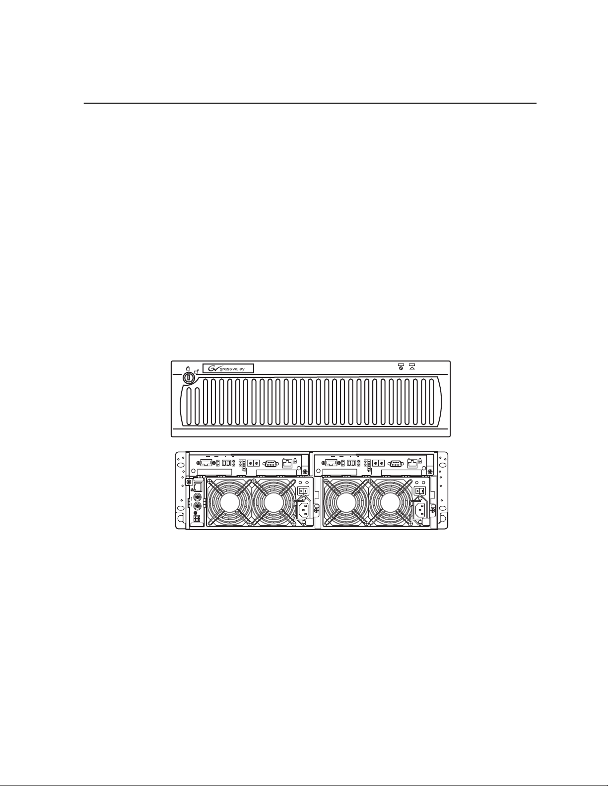
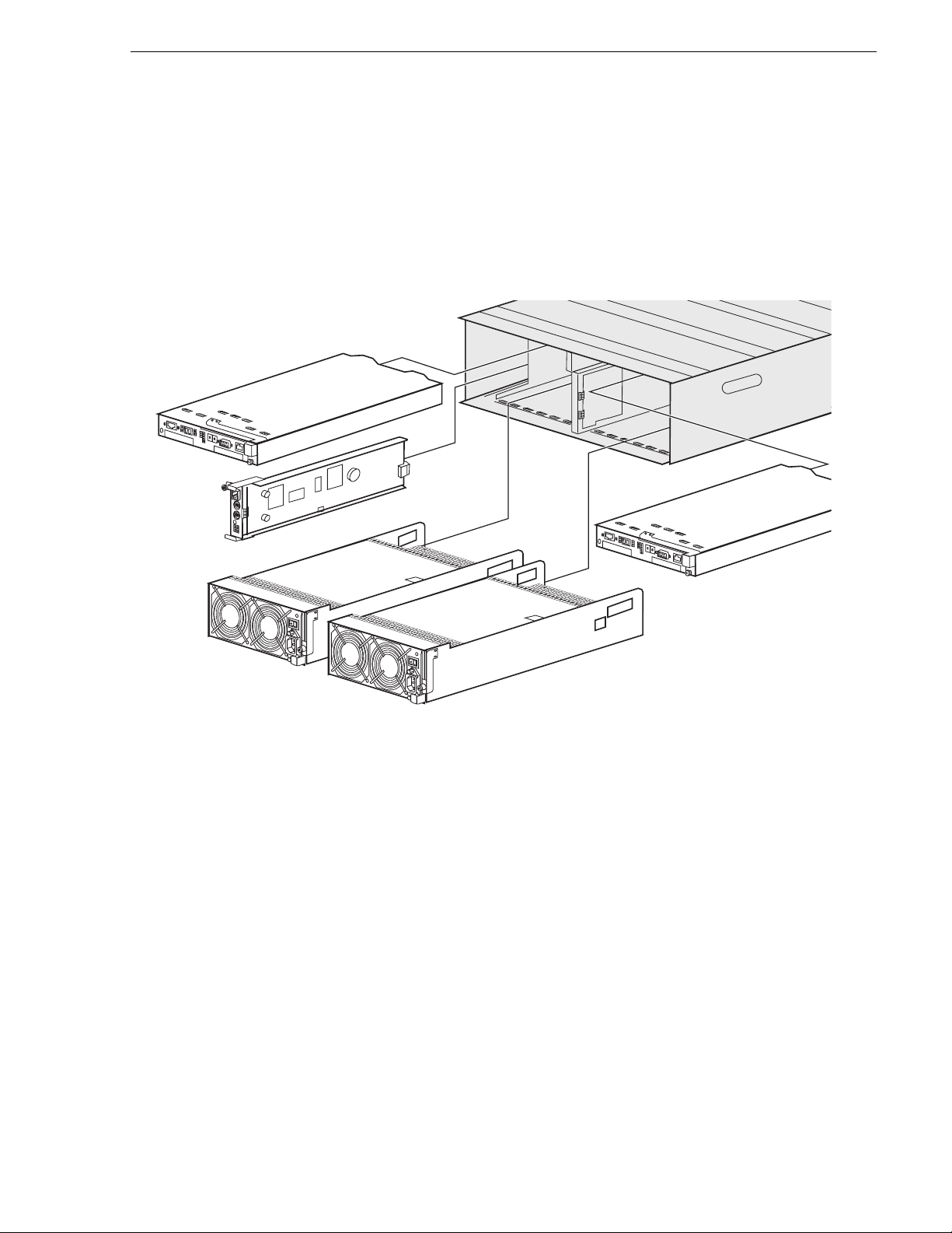
The following figure shows the RAID Storage Chassis components. Details on each
component follow the figure.
Chassis
LAN Card
Power Supply 1
Chassis
Controller 0
Power Supply 0
NOTE: Every K2 Level 2 RAID chassis power supp ly inc lud es a backup battery so
that if electrical powe r is lost, data stor ed in cache memory will be saved. Dat a store
cache is not used in the K2 Level 2 RAID, so the Battery Backup module is not used,
even though it ships as part of the power supply.
The chassis is a sheet-metal hou sing that contains a passive midpl ane and chassis slots
for the RAID controllers or expansion adapters, disk drives, power supplies, and the
LAN card.
A RAID chassis (which houses one or two RAID controllers) has a pre-set chassis
address of 0. An expansion chassis (which houses one or two expansion adapters)
must have its chas sis address set to 1. This addre ss is set by a c ontrol on th e expansion
adapter. Refer to your K2 Storage System Instruction Manual for information on
setting the chassis address switch. See also, “Addressing requirements” on page 27.
September 8, 2006 Level 2 RAID Instruction Manual 19
Page 20
Chapter 1 About the K2 Level 2 RAID storage
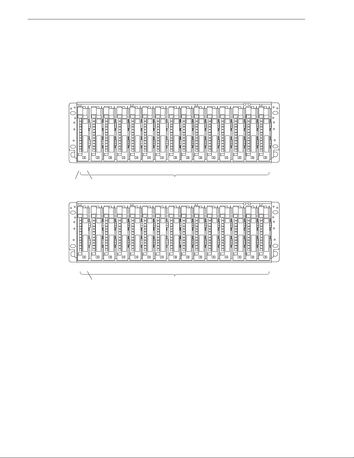
The following diagram shows how disk modules are identified based on the chassis
address and physical location. The chassis with an address set to 0 contains drives
from 0 to 14; the expansion chassis with an address set to 1 contains drives from 16
to 30. There is no drive 15 in the numbering sequence.
Primary chassis
0 000 010 020 030
Chassis
Address
Expansion chassis
starts with disk 16.
There is no disk 15.
Disk
ID
Expansion chassis
1 161 171 181 191
04
0 050 060 070 080 090 100 110 120 130
Disk Modules
20
1 211 221 231 241 251 261 271 281 291
Disk Modules
An operating primary RAI D chassis must have, at a mini mum, the fir st three ph ysical
drives (0 - 2) installed, as the RAID configuration information is written to these
drives. Microcode is also written to these disks when RAID controller microcode is
loaded.
14
30
Midplane
The midplane distribute s power and si gna ls to all the chassis compone nts . All FRUs
plug directly into midplane connec tor s.
Disk modules
Each disk module consists of a Fibre Channel disk drive in a carrier assembly. If a
disk drive fails, and needs replacing, you can do so while the RAID Storage Chassis
is powered up. Replacement disk drives begin rebuilding immediately after being
installed. (See “Removing and installing disk modules” on page 47.)
20 Level 2 RAID Instruction Manual September 8, 2006
Page 21
K2 Level 2 RAID Circuit board modules
The disk drives are 3.5-inch FC-AL drives that conform to the Fibre Channel
Arbitrated Loop (FC-AL) standards and support dual-port FC-AL interconnects
through the two RAID controllers and their cabling.
NOTE: Once the K2 Level 2 External RAID is installed and configured,
the disk modules become slot dependent. Moving disk modules between
!
physical slots will result in loss of data and the need to reconfigure the
system.
K2 Level 2 RAID Circuit board modules
There are three circuit board modules used: the RAID controller module, the
expansion adapter , and the LAN card. Th e RAID c ontroll er mod ule is in the prim ary
RAID chassis. It manages the disk drives and provides a Fibre Channel interface to
the K2 Media Server system or Fibre Channel switch fabric. The expansion adapter
is in an Expansion chassis. It manages the disk drives, in conjunction with the
connected RAID controller and provides a Fibre Channel interface to the primary
chassis. The LAN card is in the primary RAID chassis only. It provides an Ethernet
port for NetCentral monitoring, a shutdown switch, and signal connections for an
uninterruptive power supply (UPS).
K2 Level 2 RAID RAID Storage Chassis circuit board modules
The K2 Level 2R includes one or two RAID controller modules. This provides
redundant Fiber Channel interface ports.
The following figure s hows a K2 Level 2 RAID RAID Storage Chass is wit h t he t wo
RAID controller modules install ed.
September 8, 2006 Level 2 RAID Instruction Manual 21
Page 22

Chapter 1 About the K2 Level 2 RAID storage
AC
100—
240V
GOOD
FLT
PWR
A1
AC
100—
240V
GOOD
FLT
PWR
A1
AC
100—
240V
GOOD
FLT
PWR
AC
100—
240V
GOOD
FLT
PWR
RAID Controller 1
DE
HOST
DISK LINK
LINK
0
UPS
1
SDN
FLT
SDN
LAN
PC
RDY
LNK
LINK
PC
2G 2G
MATE
LINK
Ethernet Port
Card
The RAID controller module has two Fibre Channel ports: the Host Fibre Channel
Port and the Expansion Chassis Port. The Host Fibre Channel Port requires LCC
cables (optical) for the Fibr e Ch anne l conn ection to a K2 Media Server or to a Fibre
Channel switch. The Expansion Chass is Port requi res HSSDC cables (copper) f or the
Fibre Channel connect ions with a K2 Level 2. Thi s extends th e Fibre Channe l loop of
the corresponding K2 Level 2 RAID chassis. There is a port sta tus LED for each Fibre
Channel por t. Refer to “Interpreting controller status LEDs” on page 43.
When the redundant Fiber Channel option is not installed in the K2 Level 2 RAID
RAID Storage Chassis, only one RAID cont rol le r is ins ta ll ed. A bla nk fi ll s t he ot her
RAID controller slot.
A diagnostic cable is provided for communication of system status information
between the RAID controller and an expansion adapter. This is required, and it
supports the NetCentral monitoring software. Refer to your K2 Media Client Sy st em
Guide for information how these connectors are used.
HOST ID
READY
ACCESS
BACKUP
FAULT
DE-DIAG
READY
GOOD
FLT
PWR
100
240V
AC
Expansion
Chassis
Port
DE
LINK
PC
2G 2G
A1
Host Fibre
Channel Port
RAID Controller 0
HOST
DISK LINK
HOST ID
LINK
PC
READY
MATE
ACCESS
LINK
BACKUP
FAULT
Status
LEDs
DE-DIAG
READY
GOOD
FLT
PWR
100
240V
AC
A1
Serial
Port
Expansion chassis
diagnostic connector
K2 Level 2
The K2 Level 2 RAID includes a LAN card with an RJ-type connector for Ethernet
network connection. It is through this connection that SNMP status information is
communicated, for monitoring by the NetCen tral system.
RAID Expansion Chassis circuit board modules
The K2 Level 2 RAID Expansion Chassis has two exp ansion adapters as shown in the
following figure.
Expansion Adapter 1
FC –OUT FC –IN
FLT
RDY
ENC ID
DIAG RDY
DIAG ID
PORT1
DE—DIAG
PORT0
GOOD
AC
100
FLT
PWR
240V
Status
LEDs
FLT
RDY
chassis
Expansion Adapter 0
FC –OUT FC –IN
ENC ID
RAID
Port
Expansion chassis
diagnostic connector
DIAG RDY
DIAG ID
PORT1
DE—DIAG
GOOD
AC
PORT0
100
FLT
PWR
240V
22 Level 2 RAID Instruction Manual September 8, 2006
Page 23

The expansion adapter in the K2 Level 2 has two Fibre Channel ports: FC-IN and
RDY
LNK
READY
ACCESS
BACKUPBACKUP
FAULT
HOST
LINK
READY
ACCESS
BACKUPBACKUP
FAULT
HOST
LINK
FC-OUT. HSSDC (copper) Fibre Channel cabling connects the FC-IN port to a K2
Level 2 RAID. This extends the Fib re Channel loo p of the corres ponding K2 Level 2
RAID chassis. There is a port status LED for each Fibre Channel port. Refer to
“Interpreting expansion adapter status LEDs” on page 45.
An expansion chassis diagnostic connectio n is provided for co mmunication of system
status information between the RAID controller and an expansion adapter. This is
required to use the NetCentral monitoring software. Refer to your K2 Storage System
Instruction Manual for information how these connectors are used.
NOTE: The K2 Level 2 Expansion chassis and K2 Level 2 RAID Controller chassis
must be powered on and off in the proper sequence. Refer to proper power
procedures in Chapter 2, “K2 Level 2 RAID Installation Information”.
Power supplies
There are two auto-ranging power supplies, power cord and standby switch. Each
supply supports a fully configured K2 Level 2 External RAID and shares load
currents with the othe r supply, if it is presen t. The power supplies are des igned so as
to protect the disk drives if you install them while the K2 Level 2 External RAID is
powered up. A disk with power-related faults will not adversely affect the operation
of any other disk.
Power supplies
The RAID chassis and the expansion chassis each have their own type of power
supply. The two types are not interchangeable.
FAULT
GOOD
AC
PWR
100—240V
Power Supply 0
FLT
RDY
LNK
Power Supply 1
FAULT
GOOD
AC
FLT
PWR
100—240V
Each power supplies includes two fan modu les used to cool the compone nts inst alled
in the K2 Level 2 External RAID chassi s. Each power supply has sta tus LEDs visible
from the rear pan el. The st atus LEDs are d escri bed in th e “ Interpreti ng power supply
status LEDs” on page 47. You can add or remove one power supply in the RAID
Storage Chassis while the RAID Storage Chassis is powered up.
September 8, 2006 Level 2 RAID Instruction Manual 23
Page 24

Chapter 1 About the K2 Level 2 RAID storage
Configurations
The K2 Level 2 RAID minimum and maximum configurations are as follows.
K2 Level 2
RAID
Configuration
minimum
(level 2)
maximum
(level 2R)
RAID Controllers Power Supplies Disk Modules LAN Cards
12 51
22 151
The maximum configurati on provides the most redundancy, and ther efore the highes t
degree of system availability.
The K2 Level 2 RAID Expansion Chassis minimum and maximum c onfigurations are
as follows.
K2 Level 2
Expansion
Chassis
Configuration
minimum
(level 2)
maximum
(level 2R)
Expansion Adapter Power Supplies Disk Modules LAN Cards
22 50
22 150
IMPORTANT: Grass Valley does not support mixing disk drives of differing
capacities in any RAID chassis . All disk drives in any RAID chass is must be of the
same capacity. For example, if a K2 Level 2 RAID and a K2 Level 2 Expansion
Chassis are connected, all the disk driv es in bot h the K2 Level 2 RAID and the K2
Level 2 Expansion Chassis must be of the same capacity.
24 Level 2 RAID Instruction Manual September 8, 2006
Page 25

Chapter 2
K2 Level 2 RAID Installation Information
This chapter describes information you’ll need to install the K2 RAID Storage (K2
Level 2 Expansion Chassis). Major topics are:
• “Installation requirements”
• “Installing a K2 Level 2 RAID Storage in an equipment rack”
• “K2 Level 2 RAID Sto rage power-up and in itialization”
• “K2 Level 2 RAID Storage power-down”
Installation requir ements
This section describes the following requirements:
• “Site requirements” on page 25
• “Controller configuration requirements” on page 26
• “Addressing requirements” on page 27
• “Cabling requirements” on page 30
• “Binding disk modules into groups” on page 30
Site requirements
For proper K2 Level 2 Expansion Chassis operation, the installation site must
conform to certain environmental specifications. These are detailed below and in
Chapter 4, K2 Level 2 RAID Technical Specifications and Operating Limits.
Power
Refer to “AC power requirements” on page 61 for AC power requirements. The
values indicate eit her the values for the power cord of a K2 Level 2 Expansion Chassis
with a single power supp ly, or the total values shared by the line cords of two powe r
supplies in the same K2 Level 2 Expansion Chassis, with the division between the
power cords and supplies at the current sharing ratio. If one of the two power suppli es
fails, the remaining supply and cord must support the full load. You must use a rack
mount cabinet with ac power distribution, and have main branch ac distribution that
can handle these values for the number of K2 Level 2s and K2 Level 2 Expansion
Chassis units that you will interconnect.
Cooling
Make sure your si te has air condition ing of the correct s ize and pla cement to mai ntain
the specified ambient te mperatu re range. The air cond itio ning must be able to handle
the requirements of th e K2 Level 2s and any connected K2 Level 2s as indicat ed under
“Environmental limits” on page 62.
September 8, 2006 Level 2 RAID Instruction Manual 25
Page 26

Chapter 2 K2 Level 2 RAID Installation Information
Controller configuration requirements
The default settings for the controller DIP switches are shown in the following
illustrations and table. Remove the controller, as explained in “Removing a RAID
controller or expansion adapter” on page 50, and verify that the default settings are
intact.
OFF
Access DIP switches
from the bottom of the
controller module
A9D A9E1 A9E2
Connector on
backboard side
of controller
4321 4321 4321
123456789ABC
Verify these settings
Switch position Bit position Setting position and function
A9E2 1 Fixed to OFF (HDD Spin-up Mode, OFF: Command, ON: Auto)
2 Fixed to ON (Operation Mode, OFF: NF1200, ON: NF1300)
3 OFF by default (Topology, OFF: FC_AL, ON: Fabric)
4 Fixed to OFF (MD Mode, OFF: Normal, ON: Long MD)
A9E1 5 Fixed to ON
6 Fixed to OFF
7 Fixed to OFF
8 Fixed to OFF
26 Level 2 RAID Instruction Manual September 8, 2006
Page 27

Switch position Bit position Setting position and function
A9D 9 Fixed to OFF
A Fixed to OFF (SES MODE, OFF: SFF8067, ON: ESD)
B ON by default (HOST MODE, OFF: 1Gbps, ON: 2Gbps)
C ON by default ( EXPANSION CHASSIS MODE, OFF: 1Gbps, ON: 2Gbps)
Addressing requirements
There are two addresses for the K2 Level 2: the Fibre Channel Arbitrated Loop
address ID (FC-AL address ID) and the chassis address.
FC-AL address ID
Each node (such as a RAID control ler) on the Fibre Channe l front-end loop must have
a unique FC-AL address ID. The FC-AL protocol translates the FC-AL address ID
into an 8-bit arbitrated loop physical address (ALPA). You set the RAID controller
FC-AL address ID using switches, as explained later in this chapter. The K2 Level 2
does not allow an ID of zero. If your K2 Level 2 has a second, redundant RAID
controller , it must be se t to a different FC-AL address ID than the primary FC.
Addressing requirements
When using redundant RAID controllers, set the FC-AL ID on the cont ro llers for all
K2 Level 2 RAIDs connected as indicated in the following table.
Number of
K2 Level 2
RAIDs
1First1 2
2First
3First
K2 Level 2
RAID
chassis
Second
Second
Third
Primary
Controller (0)
FC-AL ID
1
2
1
2
3
Redundant
Controller (1)
FC-AL ID
3
4
4
5
6
The valid FC-AL address ID range is a number 1 through 125 decimal, which is 01
through 7D hexadecimal. The following figures and table locate the switches and
show how to select ID numbers using them.
Left FC-AL address ID switch
PC
DE
HOST
LINK
PC
2G 2G
LINK
MATE
LINK
DISK LINK
HOST ID
0
READY
ACCESS
BACKUP
FAULT
Right FC-AL address ID switch
1
DE-DIAG
READY
September 8, 2006 Level 2 RAID Instruction Manual 27
Page 28

Chapter 2 K2 Level 2 RAID Installation Information
0
1
Address ID Left Switch Right Switch
101
202
Address ID = 1
.
.
.
909
10 0 A
11 0 B
.
.
.
15 0 F
16 1 0
17 1 1
.
.
.
25 1 9
26 1 A
27 1 B
.
.
.
.
.
.
.
.
.
.
.
.
.
.
.
.
.
.
.
.
.
.
.
.
.
.
.
31 1 F
32 2 0
Chassis address setting requirement
The chassis address for a K2 Level 2 primary RAID chassis is pre-set at 0 and does
not need to be configured.
Each K2 Level 2 expansion chas sis must have its chassi s address set to 1, whic h is the
factory-set value. This is set by the chassis a ddress swit ch, which is located on the
expansion adapter. The following figure identifies the switch.
28 Level 2 RAID Instruction Manual September 8, 2006
Page 29

Addressing requirements
FC –OUT FC –IN
FLT
RDY
ENC ID
DIAG RDY
DIAG ID
PORT1
DE—DIAG
Chassis address switch
Set the switch to 1 for both the left and right expansion adapters installed in the
Expansion chassis.
NOTE: When the switches of the left and right adapters are set differently, the
FAULT LEDs blink and the Expansion chass is is not started. If different values are
set, turn off the power of the system including the Expansion chassis, re-set the
values to
1, and turn on the power again.
Expansion chassis diagnostic switch setting requirement
A K2 Level 2 primary RAID chassis has no expansion chassis diagnostic switch, so
no configuration is necessary.
The expansion chassis diagnostic ID switch sets the diagnosis path address of the
Expansion chassis. This is required for NetCentral monitoring. Each K2 Level 2
expansion chassis has the switch that must be se t to 0, which is the facto ry-se t value.
The expansion chassis diagnostic switch is located on the expansion adapter. The
following figures show how to use the switch.
PORT0
FC –OUT FC –IN
FLT
RDY
Set the switch to
0 for both the left and right expansion adapters installed in the
Expansion chassis.
DIAG RDY
4 3 2 1
ENC ID
DIAG ID
PORT1
DE—DIAG
Expansion chassis diagnostic switch
4 3 2 1ON
ID = "0 "
PORT0
September 8, 2006 Level 2 RAID Instruction Manual 29
Page 30

Chapter 2 K2 Level 2 RAID Installation Information
Cabling requirements
It is recommended that you use th e Fibre Channel cable s shipped with your K2 Level
2 Expansion Chassis when making connections. For cable specifications, refer to
“Cable lengths” on page 61.
Optical cables must meet the app ropriate 2-Gbit FC-AL loo p standards. You must use
this type of cable to connect a host to the K2 Level 2 controller.
Copper cables must meet the appropriate standards for 2-Gbit FC-AL loops. You
must use this type of cable to connect Expansion chassis.
K2 Level 2 and K2 Level 2 interconnections should maintain consistency. Tha t is, one
FC loop should connect the K2 Level 2’s RAID controller 0 and the K2 Level 2’s
expansion adapter 0. The other FC loop should connect the K2 Level 2’s RAID
controller 1 and the K2 Level 2’s expansion adapter 1. If your K2 Level 2 does not
have RAID controller 1, do not connect any cabling to the K2 Level 2’s expansion
adapter 1.
Do not leave an unused (that is, dangling) cable connected to a Fibre Channel port
because it may cause excess noise on the loop.
Diagnostic cables connec t K2 Level 2 and K2 Level 2 units. These ca bles are required
for the communication of s tatus inform ation between chas sis, and support Net Central
monitoring.
NOTE: Also refer to the K2 Storage System Instruction Manual for cabling
diagrams and step-by-step instructions.
Binding disk modules into groups
After cabling a K2 Level 2 and any K2 Level 2s, you must bind disk modules into
LUNs using the Storage Utility provided by Grass Valley. Refer to the K2 Storage
System Instruction Ma nual for informati on on using the Storag e Utility to bind drive s.
NOTE: Make sure you allow adequate time for binding disk modules into LUNs.
PFR500 and PFR600 controllers bind each LUN in turn, but take less than a
minute for each LUN. PFC500 and K2 Level 2 controllers bind multiple LUNs at
the same time, yet take more than an hour to bind a LUN. Large drive capacities
and multiple LUNs can increase the binding time to 10 hours or more.
30 Level 2 RAID Instruction Manual September 8, 2006
Page 31

Installing a K2 Level 2 RAID Storage in an equipment rack
Installing a K2 Level 2 RAID Storage in an
equipment rack
Use the information in this section to unpack the K2 Level 2 RAID Storage chassis
and mount in an equipment rack.
Procedures include:
• “Unpacking the chassis”
• “Installing the rack mounts”
• “Inserting the K2 Level 2 RAID Storage chassis in the rack”
Unpacking the chassis
Unpack the K2 Level 2 Expansion Chassis chassis, cables, and installation kit, as
illustrated by the diagram on the outside of the packing box.
!
ship.
NOTE: A K2 Level 2 Expansion Chassis chassis is heavy. Two people
should lift and move it.
NOTE: Save the chassis packaging. Use only K2 approved packaging to
Installing the rack mounts
The following diagram and procedure describe installing the right side rail.
Installation is similar for the left side rail.
September 8, 2006 Level 2 RAID Instruction Manual 31
Page 32

Chapter 2 K2 Level 2 RAID Installation Information
Front
channel
mount
Inner
rail
Rail
adjustment
screws
Outer
rail
Guide
Bracket
Rack
Bracket
Rack
Bracket
Guide
Bracket
Back
channel
mount
Rack
Bracket
M3
screws
Back
channel
mount
Guide
Bracket
(Type T for
threaded holes,
Type H for
round holes)
Guide
Inner
rail
Bracket
(Type T for
threaded holes,
Type H for
Front
channel
mount
round holes)
Outer
rail
Rack
Bracket
Back
channel
mount
Guide
Front
Bracket
channel
Inner
mount
rail
Guide
Bracket
Rack
Outer
Bracket
rail
Rail
adjustment
screws
Rack
Bracket
Rail
adjustment
screws
M3
screws
To install the K2 Level 2 RAID Storage rack mounts:
1. Remove the rack brack ets from the g uide bracket s at both ends of the rail. Sav e the
rack brackets and the M3 screws, as they are used later in this procedure.
Guide
Bracket
Rack
Bracket
M3
screws
2. If your rack has 10-32 t hreaded ho les, sk ip ahead to the nex t step in thi s procedur e.
If your rack has 0.281 -i nch round holes, at both ends of the rail repl ac e t he T type
guide brackets with the H type guide brackets.
32 Level 2 RAID Instruction Manual September 8, 2006
Page 33

Inserting the K2 Level 2 RAID Storage chassis in the rack
Rack
Bracket
Guide
Bracket
H type
Guide
Bracket
T type
Rack
Bracket
3. Loosen the rail adj ustment screws so that the inner rail slides freely.
4. Align the mounting holes on the outer rail guide bracket with the front channel
mount holes. The protrusions on the guide bracket guide the rail to appropriate
positions on the rack.
5. Place the two M3 mounting screws through the rack bracket, through the front
channel mount holes, a nd into the mounting holes on the guide brac ket. Tighten the
screws to secure the outer rail to the front channel mount.
6. Move to the rear o f the rac k and pul l the inne r rail t oward you to align the inner rai l
guide bracket mounting holes wit h the back channe l mount holes . The protrusi ons
on the guide bracket guide the rail to appropriate positions on the rack.
7. Place the two mounting scre ws through the rac k bracket, th rough the back chann el
mount holes, and into the mounting holes on the guide bracket. Tigh ten the screws
to secure th e outer rail to the back channel mount.
8. Firmly tighten the rail adjustment screws.
9. Repeat this procedure for the other side rail.
Inserting the K2 Level 2 RAID Storage chassis in the rack
1. Rest the chassis on t he supp ort angle s shown. Sl ide t he chas sis b ack and int o plac e
2. Secure the chassis to the rack with the 10-32 mounting screws. On racks with
threaded holes the mounting screws engage the rack’s threaded holes. On racks
without threaded holes the mounti ng scr ews enga ge the H type guide bracke t’ s
threaded holes.
September 8, 2006 Level 2 RAID Instruction Manual 33
Page 34

Chapter 2 K2 Level 2 RAID Installation Information
Support
angle
Mounting
screws
3. At the rear of the rack, insert and tighten the 10-32 mounting screws, with cable
clamps, through the rear ra ck bracke ts. On ra cks with threaded holes the mountin g
screws engage the rack’s threaded holes. On racks without threaded holes the
mounting screws engage the H type guide bracket’s threaded holes.
34 Level 2 RAID Instruction Manual September 8, 2006
Page 35

Inserting the K2 Level 2 RAID Storage chassis in the rack
Cable
clamps
The 10-32 screws in the rear provide necessary reinforcement to the M3 screws.
4. Repeat this procedure to i nsert each K2 Level 2 RAID Storage chass is in the rack.
September 8, 2006 Level 2 RAID Instruction Manual 35
Page 36

Chapter 2 K2 Level 2 RAID Installation Information
K2 Level 2 RAID Storage power-up and initialization
This section gives information about connecting power and powering-on the
K2 Level 2 RAID Storage system.
Connecting electrical cables
For each chassis, there are two electrical cables (one for each power supply) that
should be connected to separate outside power sources.
!
!
To prevent the plug from being inadvertently disconnec ted, secure the electr ical cable
into the outlet by doing the following:
1. Check that the power switch on the RAID chassis and th ose on the host system are
all set to OFF.
WARNING: Make sure the power cords meet lo cal safety and electr ical
standards.
CAUTION: The K2 Level 2 RAID Storage system must be electrically
grounded. Operating the syst em without proper grounding can damage
disk drives. If the outlet you use is not grounded, make sure that a
licensed electrician replaces it and installs a grounding conductor.
2. Insert the power cord into the power supply.
3. Secure the power cord with the stopper.
4. Insert the plug of the power cord into an AC outlet. Use a grounded AC outlet.
Powering-up the K2 Level 2 RAID Storage system
1. Power-up the K2 Level 2 Expansion cha ssis pri or to or at the same time as the K2
Level 2 Controller chassis.
NOTE: You must always power-up the K2 Level 2 Expans ion chassis prior to , or at
the same time as, the K2 Level 2 RAID controller chassis. Failure to do so may
prevent some LUNs in the expansion chassis from being recognized.
36 Level 2 RAID Instruction Manual September 8, 2006
Page 37

K2 Level 2 RAID Storage power-down
Before turning on the AC power, c heck fo r loos e d isk dr ives by pushin g each disk
drive.
2. Turn on power switches on both power supplies.
When turning on the power switches, confirm that the POWER GOOD LEDs
(green) on all the po we r supp li es and POWER LEDs (green) on t he front panel of
the RAID chassis and Expansion chassis go on. The power supply starts, and the
POWER LED (green) is on while the power switches are on.
The RAID chassis performs the self-test and initialization immediately after the
power is turned on. When the self-test and initialization terminate and the RAID
chassis becomes ready, the READY LED of the controller stops flash ing and enters
the on state.
3. Confirm that the READY LED is on, and then turn on the host system.
The chassis takes four minutes (at maximum) to start.
Refer to sections in Chapter 3, “Servicing the K2 Level 2 RAID” for information
on interpreting status LED behavior.
NOTE: Refer to the K2 Storage System Instruction Manual for complete system
power-up procedures.
K2 Level 2 RAID Storage power-down
NOTE: If your K2 Level 2 RAID Storage system is part of a shared storag e system,
refer to the K2 Storage Syst em Instruction Manual for i nstructions on shutting down
the shared storage before powering down a K2 Level 2 RAID Storage.
To power-down the K2 Level 2 RAID Storage correctly:
1. Stop all read/write activity to the K2 Level 2 RAID Storage storage system.
2. On the RAID controller chassis, turn off power switches on both power supplies.
3. On the Expansion chassis, turn off both power switches on both power supplies.
Alternatively, turn off all power switches of the RAID controller chassis and the
Expansion chassis at the same time.
!
To turn on power, refer to “K2 Level 2 RAID Storage power-up and initializat ion” on
page 36.
CAUTION: You must always power down the K2 Level 2 RAID
controller chassis prior to, or at the same time as the K2 Level 2
Expansion Chassis.
Battery Backup
Every K2 Level 2 RAID chassis power supply includes a backup battery so that if
electrical power is lost, data stored in cache memory will be saved.
Data store cache is not used in Profile s torage syst ems, so the Bat tery Backup mod ule
is not used, even though it ships as part of the power supply module.
September 8, 2006 Level 2 RAID Instruction Manual 37
Page 38

Chapter 2 K2 Level 2 RAID Installation Information
38 Level 2 RAID Instruction Manual September 8, 2006
Page 39

Chapter 3
Servicing the K2 Level 2 RAID
This chapter describes how to monitor K2 Level 2 RAID status and replace Field
Replaceable Units (FRU).
Topics include:
• “Maintenance procedures using Storage Utility” on page 39
• “Monitoring K2 Level 2 RAID status using NetCentral” on page 39
• “Interpreting disk module LEDs” on page 42
• “Interpreting controller status LEDs” on page 43
• “Interpreting expansion adapter status LEDs” on page 45
• “Interpreting LAN card status LEDs” on page 46
• “Interpreting power supply status LEDs” on page 47
• “Removing and installing disk modules” on page 47
• “Replacing a RAID controller or expansion adapter” on page 50
• “Replacing the LAN card” on page 53
• “Replacing a power supply” on page 56
Maintenance procedures using Storage Utility
Several maintenance procedures can be performed using the Grass Valley Storage
Utility.
To perform the following tasks, refer to the K2 Storage System Instruction Manual:
• Checking RAID controller microcode version
• Loading RAID controller microcode: All models
• Identifying disk modules prior to removal
• Downloading K2 Level 2 disk drive firmware
• Disabling a K2 Level 2 RAID controller for removal
• Disabling a K2 Level 2 disk module for removal
• Configuring K2 Level 2 network and SNMP settings
Monitoring K2 Level 2 RAID status using NetCentral
You can monitor K2 Level 2 RAID Stor age systems us ing Grass Valle y’s NetCentral
monitoring software. E nabled by SNMP, NetCentral can continuously monitor the
storage system and send notifications if there is a problem. The SNMP agent software
September 8, 2006 Level 2 RAID Instruction Manual 39
Page 40

Chapter 3 Servicing the K2 Level 2 RAID
required for NetCentral monitoring resides on the RAID storage device itself. As a
result, the K2 Level 2 RAID appears in NetCentral as a standalone device rather than
as a subsystem of the K2 Media Client.
Communication with NetCentral takes place over the LAN card Ethernet port. To
monitor the K2 Level 2 RAID, you must connect network cabling, power on the
system, then configure network and SNMP settings as described in the K2 Storage
System Instruction Manual.
If you have the K2 Level 2 expansion chassis, you must connect the diagnostic
cabling, as it is required for NetCentral monitoring.
Refer to the N etCentral O n-line Help for information on monitoring the K2 Level 2
RAID with NetCentral.
40 Level 2 RAID Instruction Manual September 8, 2006
Page 41

Interpreting front panel LEDs
Use the following illustration and table to identify and interpret front panel LEDs
Interpreting front panel LEDs
Power
LED
PFR
700
.
LED Action Meaning
Power On DC power is being supplied to the chassis.
Off DC power is not being supplied to the chassis.
Service Flashing
(check
LEDs on
modules
to
identify
the
specific
fault)
Temperature alarm
Less than three system disks
A power supply, fan, battery backup unit, or controller is removed or is not
detected as on-line.
Controller down
Controller powered-off
Battery backup unit charging or is dischar ged.
POWER
Service
LED
!
SERVICE
Rapid
flashing
Fan alarm
Power alarm
Power supply off
Hard disk drive fault
Logic occluded
Logic degraded
Logic being restored
Logic being resto re d to ho t sp ar e
Chassis is between power-on and ready st ate.
Device serial number, WWName, or ProductName is nonexistent or illegal.
Waiting for input from panel.
The configuration data in the system disk does not match the actual configuration.
September 8, 2006 Level 2 RAID Instruction Manual 41
Page 42

Chapter 3 Servicing the K2 Level 2 RAID
Interpreting disk module LEDs
Use the following illustration and table to identify and interpret disk module LEDs
Fault
LED
Ready
LED
.
LED Action Meaning
Ready On Normal state. Ready.
Off Fault state
Processing commands
Flashing Sending data
Self-test and initialization immediately after power-on
Formatting
Fault
(amber)
Off Normal state
On An error has occurred on the disk drive
Slow
flashing
or off
Power turning off
42 Level 2 RAID Instruction Manual September 8, 2006
Page 43

Interpreting controller status LEDs
Interpreting controller status LEDs
Use the following illustration and table to identify and interpret controller LEDs
Expansion Chassis Link
Expansion Chassis 2G
Host Link
DE
PC
Host 2G
HOST
LINK
PC
2G 2G
LINK
DISK LINK
MATE
LINK
Disk Link
Mate 2G
HOST ID
READY
ACCESS
BACKUP
FAULT
Ready
Access
Backup
Fault
.
LED Action Meaning
Ready On Controller boot up complete
Flashing Controller bo oting up
Fault
(orange)
Access On Controll er commands are being executed via host or LAN card.
Backup
(orange)
On Controller fault state
Flashing Controller cache sweep-out failed
On
(power
Controller memor y backup state = Dirty d a ta exists. Resources must not be
replaced with new ones.
off)
DE-DIAG
READY
Expansion
Chassis Diag
Host Link On The host Fibre Cha nnel link is being executed.
Off Power on self test is being executed. Stays off if license key lock of Base
Product is not released.
Host 2G On Interface with host is operating at 2Gbps.
Off Interface with host is operating at 1Gb ps.
Expansion
Chassis
Link
Expansion
Chassis
2G
On T he expansion chassis Fibr e Channel linkup is being executed.
Off Power on self test is being executed.
On Interface with the disk is operating at 2Gbps.
Off Interface with the disk is operating at 1Gbps.
Disk Link On The internal disk channel linkup is being executed.
Off Power on self test is being executed.
Mate Link On The mate (redundant) controller linkup is being executed.
Off Power on self test is being executed.
September 8, 2006 Level 2 RAID Instruction Manual 43
Page 44

Chapter 3 Servicing the K2 Level 2 RAID
LED Action Meaning
Expansion
Chassis
Diag
On Ch assis is ready to diagnose.
Off Chassis is preparing for diagnosis.
44 Level 2 RAID Instruction Manual September 8, 2006
Page 45

Interpreting expansion adapter status LEDs
Interpreting expansion adapter status LEDs
Use the following illus tration and table to identify and inte rpret expansion adapte r
LEDs
FC –OUT FC –IN
FLT
RDY
Ready
Fault
Fibre Channel
Out Linkup
.
LED Action Meaning
Ready
(Green)
Fault
(Orange)
Fibre
Channel In
Linkup
Fibre
Channel
Out
Linkup
On Module is powered on and initial diagnostics completed normally
On Fault in the module.
Also on at power-on and then off at the completion of the self-test.
On Fibre Channel In port (from primary RAID chassis) is operable and linked up.
Off or
Self-test or initialization just after power-on.
flashing
On Fibre Channel Out port is operable and linked up. This port is not used.
Off or
Self-test or initialization just after power-on.
flashing
ENC ID
Fibre Channel
In Linkup
DIAG RDY
DIAG ID
DE—DIAG
Expansion
Chassis Diag
PORT1
PORT0
Expansion
Chasssis
Diag
On The expansion chassis is connected with the primary RAID chassis through
the diagnostic c able and ready for diagnosis.
Flashing The LED blinks just after power-on or when no expansion chassis diagnosis
cable is connected.
September 8, 2006 Level 2 RAID Instruction Manual 45
Page 46

Chapter 3 Servicing the K2 Level 2 RAID
p
Interpreting LA N ca r d sta t us LE Ds
Use the following illus tration and table to identify and interpret LAN card LEDs
0
UPS
1
SDN
FLT
SDN
RDY
LNK
Ready
Link
Swee
Fault
Cache
-out
.
LED Action Meaning
Ready On Boot up complete
Flashing Waiting for setup of initial values
Fault
(orange)
Link On Data is sent and received on the network.
Cache
Sweep-out
On Initialization is occurring. (LED on temporarily only)
Fault state
Flashing The LAN card is faulty
While scheduled stop is executed , the unit (except LAN card) on which Faul t
LED is on, is faulty.
On Cache sweep-out complete. (Scheduled stop normally terminated and ready
to power off)
Flashing Cache sweep-out in progress. (Scheduled stop is being executed, and no I/O
interrupt from host is accepted)
46 Level 2 RAID Instruction Manual September 8, 2006
Page 47

Interpreting power supply status LEDs
Interpreting power supply status LEDs
Use the following illus tration and table to identify and interpret power supply LEDs.
LED Action Meaning
Good On AC power is supplied to the chassis
Fault
(orange)
On Fault in power supply, battery backup unit, or fan
Good
GOOD
AC
Fault
FLT
PWR
100—240V
A1
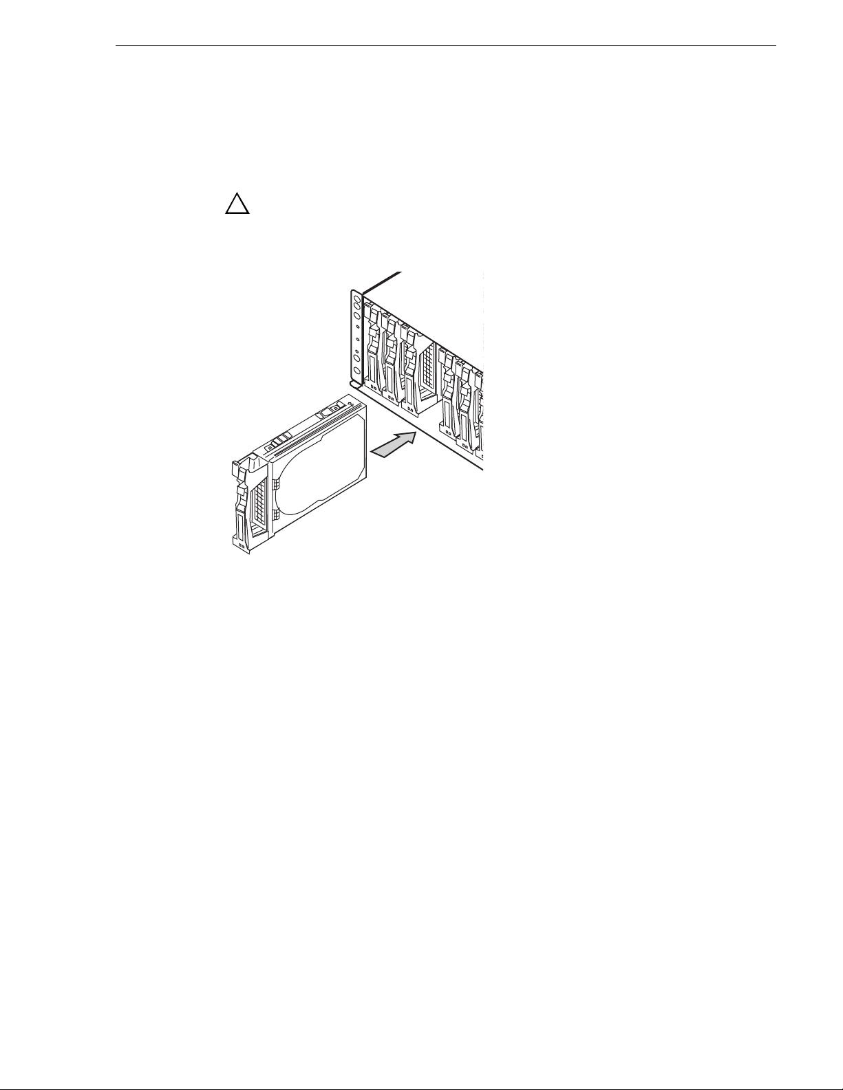
Removing and installing disk modules
!
Use the following instructions to replace a faulty disk module. It should be replaced
while the RAID chassis is running (hot-swapped).
NOTE: Grass Valley does not support mixing disk drives of differing capacities
within a RAID chassis. All disk drives in any RAID chassis must be of the same
capacity. For example, if a K2 Level 2 RAID Storage and a K2 Level 2 Expansion
Chassis are used, all the disk drives in both the K2 Level 2 and the K2 Level 2
Expansion Chassis must be of the same capacity.
Moving disk modules
!
CAUTION: If the RAID chassis does not have the r edundant controller
option, when a replacement disk module is inserted there can be a 1.5
second (maximum) disruption of video (record/play).
CAUTION: You can destroy the media file system beyond recovery if
you move a disk module to a different sl ot. The service person can move
a disk module when you don’t care about losing the media in the media
file system and under the following cautions:
September 8, 2006 Level 2 RAID Instruction Manual 47
Page 48

Chapter 3 Servicing the K2 Level 2 RAID
• The disk module must be unbound.
• Moving a drive module that i s part of a LUN to another slot makes al l informat ion
on the LUN inaccessible.
• You must remove and install the disk module while the storage system is powered
up.
A disk module must be inserted all the way or removed entirely. Do not leave a disk
module partially removed exce pt for periods when you are allowing it to spin down.
When replacing multiple disks, observe the following:
• The RAID chassis configuration i nformation is written to the first three disk
modules. If all of th ese disk modules are rep laced with new device s with the power
supplies turned off, the information is lost. This condition is indicated by the
SERVICE LED blinking at a high rate at chassis power up. Therefore, do not
replace the first three d isk modules with the po wer supplies turned off.
• When multiple disk modules are subject to replacement, they must be replaced
with new disk modules one by one. Do not replace multiple disk modules
simultaneously. Afte r checking that the Ready LED on the front panel of the
current disk module is lit, commence replacing the next disk module.
• Stick on the physical label indicating the installation position on each newly
installed disk module.
• If both disk modules in 16 and 29 (or 17 and 30) in the expansion chassis are
defective or uninstalled, the Service LED on the expansion chassis and the Fault
LED on the expansion adapter will go off. In this case, first install a sound disk
module in 16 or 29 (or 17 or 30). If the expansion adapter operates normally, the
Service LED on the expansion chassi s and the Fault LED on the expansion adapter
will go off.
!
CAUTION: Handle a disk module gently and use an ESD wristband.
Do not remove a faulty disk module until you have a replacement
module (with the same part number) or a filler module available.
Removing a disk module
NOTE: If a disk module has been bound into a LUN, do not mov e it to another slot
unless you do not care about the data on the LUN. Each module has LUN
identifying information written w hen it is bou nd. Moving it to another sl ot can
make information on the original LUN inaccessible.
Generally, you should not remove a disk module unless it is faulty. Refer to
“Interpreting fr ont panel LEDs” on pa ge 41 and “Monitoring K2 Level 2 RAID status
using NetCentral” on page 39.
NOTE: If you wish to remove an operational disk module, use the Grass Valley
Storage Utility to disable the disk before removing it.
To remove the disk module:
1. Confir m the location of the fa ulty disk module by checking its Fault LED. A lso
check NetCentral messages. NetCentral messages may report disk faults by disk
48 Level 2 RAID Instruction Manual September 8, 2006
Page 49

module number.
(
)
2. Remove the disk module as illustrated in the following diagram.
Pull ejector
1
out and up
3
Wait until the
2
disk stops spinning
about 30 seconds
Slide out
Installing disk module
Installing disk module
!
To install a disk module:
1. Wait at least three minutes after removing the previous disk module.
2. Put a location label on the replacement disk drive, as appropriate for the slot into
which it is installed.
3. Install the disk mod ule as illustr ated in the following di agram.
CAUTION: If the RAID chassis does not have the r edundant controller
option, when a replacement disk module is inserted there can be a 1.5
second (maximum) disruption of video (record/play).
September 8, 2006 Level 2 RAID Instruction Manual 49
Page 50

Chapter 3 Servicing the K2 Level 2 RAID
Push ejector
2
down until
it clicks
Upon installation the disk spins up automatically and data recovery begins.
Refer to “Interpreting controller status LEDs” on page 43 for disk module LED
status during rebuild. Afterward, check disk module status using NetCentral or
Grass Vall ey Storage Utility.
1
Slide in
Replacing a RAID controller or expansion adapter
Use the following instructions to replace a RAID controller or expansion adapter. It
should be replaced while the chassis is powered up (hot-swapped).
NOTE: Ensure that the RAID controller module you are installing has the same
microcode version as the module being replaced. Otherwise, the replacement
module will not initializ e. Refer to the K2 Storage S ystem Instr uction Manual for
information on checking contro ller firmware versions.
NOTE: A K2 Level 2 RAID must have at least one RAID controller installed. Do
not remove both RAID controllers, even in an offline condition. Since the
controllers store the configuration information of the RAID chassis or the product
license unlock information, replacing the two controllers simultaneously loses the
data.
Removing a RAID controller or expansion adapter
To remove a RAID controller or expansion adapter:
1. Identify the module to be replaced using NetCentral or verify that the module’s
Fault LED is on. If you are removing an operatio nal RAID controller, use the Grass
Valley Storage Utility to disable the RAID controller.
2. Remove the cables connect ed to the module. No te wher e the c ables connect to t he
module.
3. Loosen the ejector set screw.
50 Level 2 RAID Instruction Manual September 8, 2006
Page 51

Installing a RAID controller or expansion adapter
4. Remove the module as illustrated in the following diagram.
Swing ejector out
1
to 90 degrees
Pull
2
module
out
!
CAUTION: The module might be hot.
Installing a RAID controller or expansion adapter
To install a RAID controller or expansion adapter:
September 8, 2006 Level 2 RAID Instruction Manual 51
Page 52

Chapter 3 Servicing the K2 Level 2 RAID
1. Set DIP switches the FC-AL switches on a replacement controller to be the same
as that of the defective cont roller. Set the chassi s address s witch and the diagnos tic
switch on a replacemen t expansion adapter to be the same as that of the defective
expansion adapter. For the switch locations, see “Addressing requirements” on
page 27.
2. With the ejector open, insert th e replacement module into the empty bay. Mak e
sure the module is seated.
52 Level 2 RAID Instruction Manual September 8, 2006
Page 53

3. Close the ejector lever to seat the module.
Replacing the LAN card
4. Tighten the set screw.
5. Reconnect cabling.
6. Verify RAID controller initialization as displayed by the module’s Ready LED.
Refer to “Interpreting controller status LEDs” on page 43. If the replacement
RAID controller fails to initialize, it may have the wrong microcode version
installed. Refer to the K2 Storage System Instruction Manual for information on
checking a nd loading controller firmware.
7. Check RAID controller status us ing NetCentra l or Grass Valley Stor age Utilit y. If
required, up date the firmware to match the version on the othe r RAID controller
using Grass Valley Storage Util it y.
Replacing the LAN card
1. Remove the cables connected to the LAN card.
September 8, 2006 Level 2 RAID Instruction Manual 53
Page 54

Chapter 3 Servicing the K2 Level 2 RAID
2. Loosen the retaining screw.
3. Grasp the points as shown and pull out the defective LAN card.
54 Level 2 RAID Instruction Manual September 8, 2006
Page 55

Replacing the LAN card
4. Insert the replacement LAN card into the empty bay.
Tab
5. When the LAN card’ s tab is in p osition for i nsertion, push the projec tions at the top
and bottom of the LAN card to insert the tab.
6. Tighten the retaining screw.
7. Connect cables.
8. Configure network and S NMP settings for t he RAID chassis as described in the K2
Storage System Instruction Manual.
September 8, 2006 Level 2 RAID Instruction Manual 55
Page 56

Chapter 3 Servicing the K2 Level 2 RAID
Replacing a power supply
NOTE: Turn off the power supply before unplugging the power cor d from
!
the supply or removing the supply from the chassis.
The RAID chassis and the expansion chassis each have their own type of power
supply. The two types are not interchangeable.
Make sure the correct type of replacement power supply is on hand and you are
otherwise prepared to complete the procedure in less than five minutes. If the time
exceeds five minutes , the pro tecti ve fea ture of the RAID cha ssis t rigge rs a shut down
sequence.
To replace the power supply:
1. Identify the faulty power supply by verifying that its Fault LED is on.
2. Turn off the power switch on the faulty power supply.
3. Unlatch the stopper to release and unplug the power cord.
56 Level 2 RAID Instruction Manual September 8, 2006
Page 57

4. Loosen the set screw on the ejector.
5. Pull the ejector out and up to 90 degrees.
Replacing a power supply
6. Slide the power supply out.
September 8, 2006 Level 2 RAID Instruction Manual 57
Page 58

Chapter 3 Servicing the K2 Level 2 RAID
7. With the ejector ope n, insert the replacement power supply into th e empty bay.
8. Push the protrusion of the ejector to turn the ejector and push in the new power
supply.
58 Level 2 RAID Instruction Manual September 8, 2006
Page 59

9. Secure the ejector with the screw.
Replacing a power supply
10.Plug the power cord in the new power su pply and s ecure the power cord by firmly
fitting the r emoval protection mec hanism.
11.Turn on the power switch.
12.Check that the Good LED of the new power supply is on.
13.Monitor the status of the power supply using NetCentral.
September 8, 2006 Level 2 RAID Instruction Manual 59
Page 60

Chapter 3 Servicing the K2 Level 2 RAID
60 Level 2 RAID Instruction Manual September 8, 2006
Page 61

Chapter 4
K2 Level 2 RAID Technical Specifications and Operating Limits
AC power requirements
Item Measurement
Input voltage 100 to 240 VAC ±10% (×2), 50/60 Hz
Maximum power consumption
a.
While the chassis can accept power of 100 - 240 VAC (50/60 Hz), the included power cord
can only accept 100 VAC. Use 100 VAC (50/60 Hz) when the included power cord is used.
If one of the two p ower supplies fa ils, the rema ining supply and cord must support the
full load. Your rackmount ca binet must include AC power distrib ution that can handle
these values.
a
550 VA
Expansion chassis: 520 VA
Size and weight
Item Measurement
Height 13 1 mm (5.16 in) (3 rack uni ts)
Width 482 mm (19 in)
Depth 594 mm (23.4 in) including front cover
Weight Approx. 45 kg (99 lbs) wit h maximum configuration
Cable lengths
It is recommended that yo u use the Fibre Ch annel cab les s hipped wi th your K2 Level
2 RAID Storage when making connections.
Optical cables must meet the appropriate standards for 2-Gb/s FC-AL loops. Such
cables are duplex LC cables with lengths up to 300m on 50/125μm MMF, or up to
150m on 62.5/125
Copper cables are used to connect the RAID chassis with the expansion chassis.
Copper cables must meet the appropriate standards for 1-Gbit FC-AL loops. Such
cables are fully shield ed, twin-axial, full-dupl ex cables. Cables greate r than 10 meters
must be equalized; c ables equal to or less th an 10 mete rs do not nee d to be equal ized.
Do not use copper cables longer than 2 meters.
μm MMF.
September 8, 2006 Level 2 RAID Instruction Manual 61
Page 62

Chapter 4 K2 Level 2 RAID Technical Specifications and Operating Limits
Environmental limits
The system includes two temperature level sensors used to issue auto-warning and
auto-shutdown in case the over temperature limit is reached.
Environmental condit ion Op e r ating Halting
Ambient temper ature 5°C to 40°C (41°F to 104°F) -10°C to 60°C (14°F t o 140°F)
Relative humidity 10% to 80% 10% to 80%
Wet-bulb temperature
Allowable vibration level 0.25 G 0.5 G
a.
The halting status includes the packaged stat us in shipping carton and the storage s tatus.
b.
Without condensation
b
0°C to 27°C (32°F to 81°F) -8°C to 29°C (18°F to 84°F)
Life expectancies of components
Item Measurement
Battery 2.5 year s
Fan (power supply) 50,000 hours
a
62 Level 2 RAID Instruction Manual September 8, 2006
Page 63

Glossary
The terms and definitions listed below are related to the storage system described in
this manual. Understanding them will aid your understanding of the storage system.
ALPA (arbitrated loop physical address)
An 8-bit address that uniquely identifies a device on an FC loop.
bind
In the context of a disk-array storage system, the procedure by which you
hardware-format one or more disk modules into one LUN (logical unit) - usually as
one of several types of RAID group.
BTU (British Thermal Unit)
A standard measure of a device’s heat output.
cache
See storage-system caching.
CA (chassis address)
A number, set to 0 on a RAID chassis, that helps establish a unique address for each
disk module on an FC-AL loop. You must set the CA on each RAID Expansion
Chassis. Since the RAID chassis CA is 0, set the Expansion Chassis CA to 1.
disk-drive module
Another name for disk module.
disk unit
A short name for physical disk unit.
disk module
A self-contained disk drive that slides into one of the slots in the front of the s torage
system. It consists of the carrier assembly, which holds the disk drive and the
regulator board. Also called disk-drive module.
DIMM (dual in-line memory module)
A type of memory module used in RC memory for write cachi ng or RAID 3 memory.
EMI (electromagnetic interference)
Electronic radiation emitted by an electrical device. The levels of EMI are strictly
controlled for da ta p roc ess ing equipment. The EMI standa rd s are explained after t h e
Notice page near the beginning of the manual.
ESD (electrostatic discharge)
The discharge of an accumulated electrical charge (static). This can severely damage
delicate electronic circuits and you should take steps to prevent this, as explained in
the Chapter 3, “Servicing the PFR 600 Series RAID”.
FC-AL (Fibre Channel arbitrated loop)
An arrangement of Fibre Channel stations such that messages pass from one to the
next in a ring.
September 8, 2006 Level 2 RAID Instruction Manual 63
Page 64

Glossary
FC-AL address ID
A number that identifies a device as a node on a fibre channel loop. You select the
FC-AL address ID using switches on the RAID controller.
Fibre Channel Disk board
The name fo r the printed-circuit board within th e K2 Media Server that allows the
server to acce ss t he Fibre Channel loop and thence th e disk drives within a K2 Level
2 Expansion Chassis.
field-replaceable unit
See FRU (fie ld-replaceable unit).
FRU (field-replaceable unit)
A hardware assembly that can be replaced on site, instead of at the point of
manufacture.
hot repair
See replace under power.
hub
An FC_AL switching device that allows multiple servers and t ar get s s u ch a s st ora ge
systems to connect at a central point. A single hub configuration appears as a single
loop.
K2 Level 2 RAID Storage
A storage s ystem that includes a chassis, up to 15 disk modules, one or two RAID
controllers, one LAN card , and one or two power suppli es. A K2 Level 2 ca n support
one K2 Level 2 Expansion Chas sis (with up to 15 disk mod ules) in additi on to its own
15 disk modules, for a total of 30 disk modules.
K2 Level 2 Expansion Chassis
A storage system that includes a chassis, up to 15 disk modules, one or two expansion
adapters, and one or two power supplies.
LUN (logical unit)
One or more disk modules (each having a head assembly and spindle) bound into a
group - usually a RAID group. The operating system sees the LUN, which includes
one or more disk modules, as one contiguous span of disk space.
memory module
See RC memory module.
node
Any device with a Fibre Channel interface that connects to a Fibre Channel loop.
power supply
An essential element of the storage-s ystem power supply. A sto rage syste m can have
two power supplies. With two, it can sur vive failure of one supply . You can replace a
power supply under power, without interrupting applications.
64 Level 2 RAID Instruction Manual September 8, 2006
Page 65

PLDA (private loop direct attach) profile
A standard for FC-AL disk drives.
RAID controller (RC)
See RC (RAID controller).
RC (RAID controller)
A printed-circuit board with memory modules and control logic that manages the
storage-system I/O between the K2 Media Server FC adapter and the disk modules.
For higher availability, a K2 Level 2R can use a second RC.
RC memory module
A memory module (DIMM or SIMM) that provides the local storage for an RC.
replace under power
The storage syst em provides replace und er power cap ability, a llowing y ou to repla ce,
for example, a disk module or a power supply module without poweri ng down the
storage system. Applications continue while you replace the failed module.
SCSI (small computer system interface)
A well-known protocol and standard for connecting computers and peripheral
devices.
SES (SCSI enclosure services)
A functional subset of SCSI III commands that allow a server to communicate with
storage enclosures using their disk modules.
SFF
Small Form Factor Com mittee
server
In the context o f s tor ag e s yst ems, a processor tha t run s a n ope ra ti ng system and uses
a disk-array storage system for data storage and retrieval.
storage chassis
A storage device that includes a chassis, up to 15 disk modules, one or two RAID
controllers, one LAN card, and one or two power supplies.
storage-system caching
The procedure of storing disk-based data in RAM memory (in this case, DIMM
memory on an RC) temporarily to save time if the data needs to be ac cessed or
changed again soon.
September 8, 2006 Level 2 RAID Instruction Manual 65
Page 66

Glossary
66 Level 2 RAID Instruction Manual September 8, 2006
Page 67

Index
A
AC power
current draw 61
overview 25
address ID
FC-AL (Fibre Channel Arbitrated Loop)
setting 27
address switch, chassis 28
B
battery
life expectancy 62
replacement 6
Battery Backup Unit 19
binding disk modules 30
blinking disk module LEDs 41
C
cabling
max lengths 30
requirements 30
Canadian Certified Power Cords 7
Canadian EMC Notice of Compliance 8
capacity 18
certifications and compliances 7
chassis
address switch 28
description 19
dimensions 61
weight 61
circuit boards
description 22
colors, disk module LEDs 41
components 18
See FRUs (field replaceable units)
configurations 24
controller
status LEDs 43
installing 49
removing 48
disk module LED displays, interpreting 41
E
ejector lever 51
electric shock 5
EN55022 Class A Warning 8
Ethernet connector 22
expansion adapter
description 22
replacing 50
F
fan
life expectancy 62
FC-AL (Fibre Channel Arbitrated Loop)
cabling requirements 30
FCC Emission Control and Limits 7
features 17
field replaceable units (see FRUs)
fire hazard 5
flashing disk module LEDs 41
FRUs (field-replaceable units)
disk module
description 20
replacing 48
expansion adapter
description 22
replacing 50
LAN card
description 22
replacing 53
power supply
description 23
replacing 56
RAID Controller
description 21
replacing 50
D
depth, chassis 61
disk module
description 20
disk module LED colors 41
identification 20
September 8, 2006 Level 2 RAID Instruction Manual 67
G
grounding
safety 5
Page 68

Index
H
height, chassis 61
high availability features 19
I
injury precautions 5
installing
disk module 49
K2 Level 2 RAID Expansion 31
K
K2 Level 2 RAID Expansion
chassis
midplane 20
chassis dep th 61
components 18
configurations 24
description 18
disk module description 20
high availability features 19
installation requirements 25
installing in rack 33
monitoring status 39
operating limits 62
power supply, description 23
powering down 37
rear panel view 21
requirements
cabling 30
operating 62
weight 61
, 22
L
Laser 8
Laser Compliance 8
LEDs
disk modules 41
rear panel 43
life expectancies of components 62
loose cable 30
, 45, 46, 47
M
midplane board
description 20
N
NetCentral 39
P
packaging 31
power
cord 36
outlet 36
power supply
description 23
LEDs 47
replacing 56
powering-up 36
product damage precautions 5
R
rack mounting 31
RAID configuration 30
RAID Controller
description 21
replacing 50
status LEDs 43
remote monitoring 39
replacing
disk module 47
expansion adapter 50
LAN card 53
power supply 56
S
safety cert ification 9
safety ground 36
safety summary 5
safety terms and symbols 6
service safety summary 7
site requirements
see also Appendix A
size and weight 61
SNMP monitoring 39
standby switch 56
status
monitoring K2 Level 2 RAID Expansion 39
storage capacity 18
storage utility 30
support, Grass Valley 14
68 Level 2 RAID Instruction Manual September 8, 2006
Page 69

V
ventilation 5
voltage, K2 Level 2 RAID Expansion
requirements 61
W
web site, for Thomson Grass Valley 13
weight, chassis 61
width, ch assis 61
September 8, 2006 Level 2 RAID Instruction Manual 69
Page 70

Index
70 Level 2 RAID Instruction Manual September 8, 2006
 Loading...