

Page 1

K2 Edge User Manual
Document version: 4.1 - 2013/7/11
Page 2

1 Grass Valley Product Support ......................................................................................................... 4
2 About this document........................................................................................................................ 4
3 Credentials ...................................................................................................................................... 4
4 K2 Edge Front Panel ....................................................................................................................... 5
5 K2 Edge Back Panel ....................................................................................................................... 5
6 Indicators and status information .................................................................................................... 6
6.1 Power supply indicator ............................................................................................................. 6
6.2 IP Manager connection indicator .............................................................................................. 6
6.3 LAN connection indicator ......................................................................................................... 6
6.4 LEDs (hard disks) ..................................................................................................................... 7
7 Channel Presets .............................................................................................................................. 8
7.1 Introduction .............................................................................................................................. 8
8 The IP Manager ............................................................................................................................ 11
8.1 Starting the IP Manager web interface ................................................................................... 11
8.2 The LCD front panel ............................................................................................................... 11
8.3 The IP Manager menu ........................................................................................................... 12
8.4 System configuration > Network configuration ....................................................................... 13
8.5 System configuration > Channel configuration ....................................................................... 13
8.6 GPIO ...................................................................................................................................... 15
8.7 System configuration > Time settings .................................................................................... 16
8.8 System configuration > Licenses ........................................................................................... 16
8.9 System monitoring > System info ........................................................................................... 16
8.10 System monitoring > Fans .................................................................................................. 17
8.11 System monitoring > UDP Monitoring................................................................................. 17
8.12 System administration ........................................................................................................ 18
9 UDP monitoring ............................................................................................................................. 19
10 Preview Channel........................................................................................................................ 21
11 Recording .................................................................................................................................. 22
12 Configuring time settings ........................................................................................................... 27
12.1 Setting up NTP ................................................................................................................... 27
12.2 Configuring time manually .................................................................................................. 28
13 K2 Edge network ports .............................................................................................................. 33
14 K2 Edge IOs .............................................................................................................................. 34
14.1 Tiles .................................................................................................................................... 34
14.2 Bypass ................................................................................................................................ 34
14.3 Master and Slaves .............................................................................................................. 34
14.4 Genlock .............................................................................................................................. 34
15 Cross Conversion ...................................................................................................................... 35
15.1 Introduction ......................................................................................................................... 35
K2 Edge User Manual - document version: 4.1 – Page 2
Page 3

15.2 Supported broadcast formats ............................................................................................. 36
15.3 Service extraction ............................................................................................................... 38
15.4 The main Player ................................................................................................................. 40
16 GPIO .......................................................................................................................................... 42
16.1 GPIO and LTC pinning ....................................................................................................... 42
16.2 GPIO via the IP Manager ................................................................................................... 43
17 Capabilities ................................................................................................................................ 44
18 Appendix: Changing an IP-address ........................................................................................... 45
18.1 After changing the IP-address of the playout nodes ........................................................... 45
18.2 After changing the virtual IP-address of the TX/MAM-servers ................................ ............ 45
18.3 After changing the IP-address of the FTP-server ............................................................... 46
18.4 After changing the IP-address of a standalone demo server .............................................. 46
Copyright © Grass Valley USA, LLC. All rights reserved. This product may be covered by one or more
U.S. and foreign patents.
K2 Edge User Manual - document version: 4.1 – Page 3
Page 4

The IP Manager:
User: admin
Password: proot123
Accessing the system via command line:
User: root
Password: proot123
1 Grass Valley Product Support
Contact information: http://www.grassvalley.com/support/contact
U.S Technical Support: +1 800-547-4989 or +1 530 478 4148 or E-mail: Please use our online form
All other countries Technical Support: +800 80 80 20 20 or +33 1 48 25 20 20 or E-mail:
callcentre@grassvalley.com
FAQ: http://grassvalley.novosolutions.net/
Training: https://grassvalley.csod.com/LMS/catalog/Main.aspx?tab_page_id=-67&tab_id=6
Documentation can be found on the grass valley website > Resources > Smart Playout Center.
The K2 Edge Smart Playout Center Commissioning Manual describes how to commission a
Channel.
2 About this document
This document applies to K2 Edge version 4.1.
3 Credentials
The default credentials for the K2 Edge are:
K2 Edge User Manual - document version: 4.1 – Page 4
Page 5
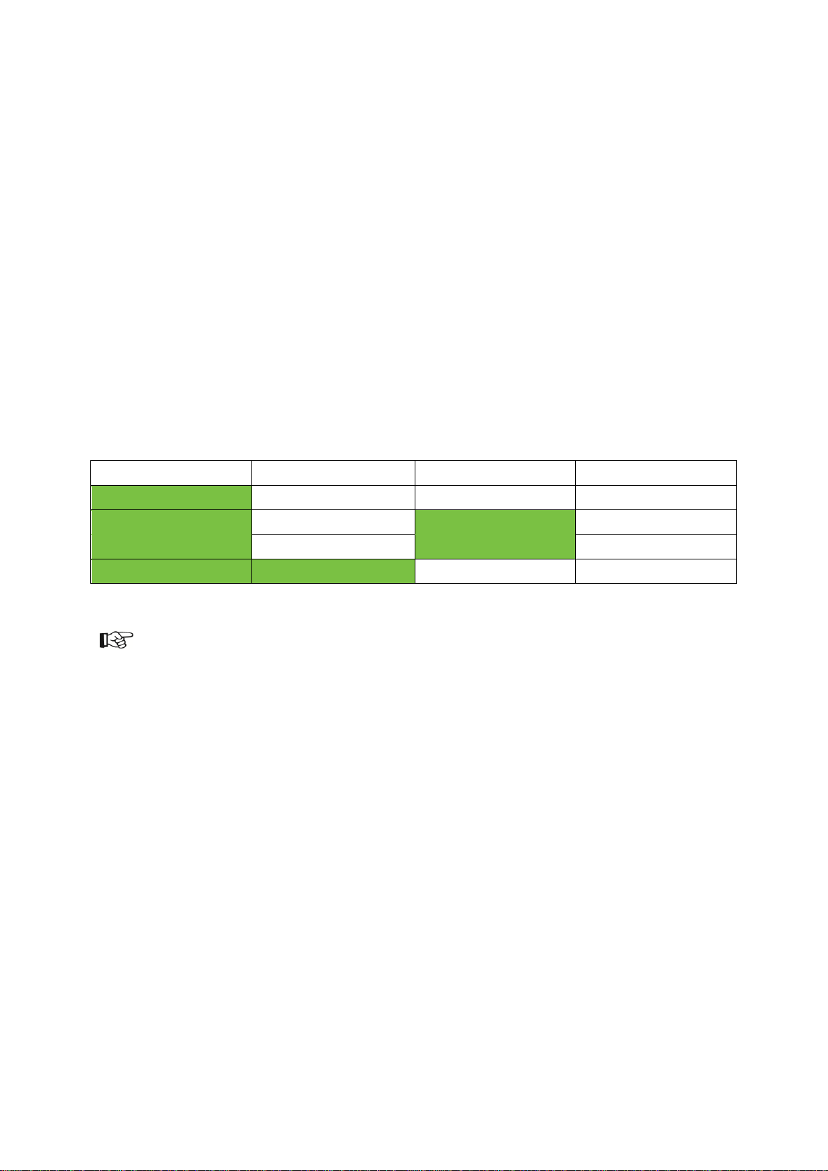
Connectors
IPM
IP Manager
M
Mouse (not connected)
KBD
Keyboard
USB
USB
COM
Serial COM
VGA
VGA
eth0-3
eth0-3
LTC
LTC
GPIO
GPIO (open collector)
AC
Power supplies
GL
blackburst/trilevel sync
IO1-IO8
SDI IOs. Bypass can be enabled on IO1 (in) and IO2 (out).
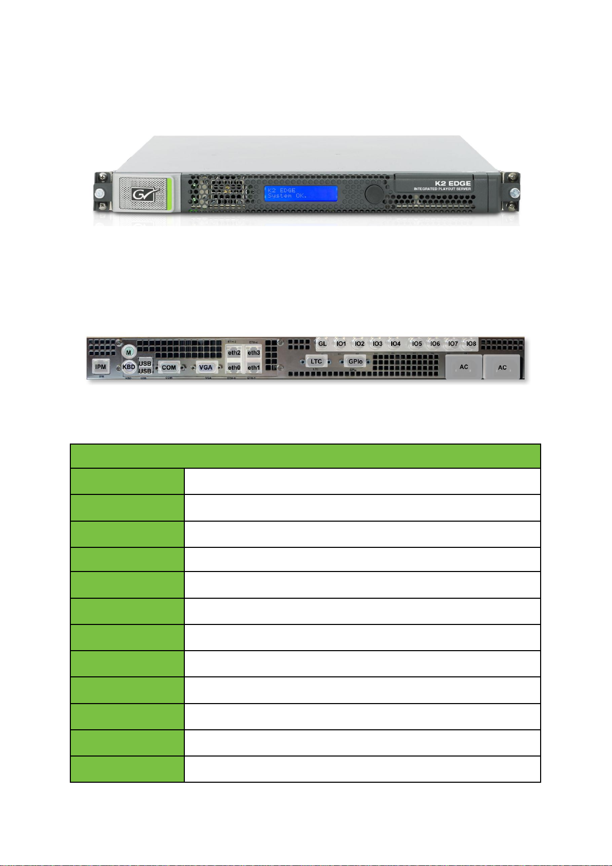
4 K2 Edge Front Panel
K2 Edge front panel with LCD-panel (IP Manager).
5 K2 Edge Back Panel
K2 Edge back panel.
K2 Edge User Manual - document version: 4.1 – Page 5
Page 6

green
ON
red
Failure
LED off
Standby
Left LED
yellow (blink)
System online
Right LED
green
Speed 100 Mbps
Left LED
green (blink)
System online
Right LED
green
Speed 100 Mbps
orange
Speed 1 Gbps
6 Indicators and status information
6.1 Power supply indicator
6.2 IP Manager connection indicator
6.3 LAN connection indicator
K2 Edge User Manual - document version: 4.1 – Page 6
Page 7

Top LED (activity)
green
Indicates read/write actions on the disk.
Bottom LED
green
Hard disk OK.
red (blink)
Hard disk not in RAID and probably broken.
orange (blink)
Hard disk will fail soon.
blue (blink)
No hard disk detected.
blue
Hard disk seems slower than usual.
green (pulse)
Hard disk is being added to the RAID (RAID rebuild).
6.4 LEDs (hard disks)
K2 Edge User Manual - document version: 4.1 – Page 7
Page 8
Single
Simulcast
Preview
Preset
HD or SD
- - hd1/hd2/sd1/sd2
HD - Preview
hdpr1/hdpr2
SD Preview
sdpr1/sdpr2
HD
SD - sim1
7 Channel Presets
7.1 Introduction
De K2 Edge contains 8 bidirectional SDI-ports. A number of presets have been defined for the K2
Edge. These presets can be selected via the IP Manager.
Possible Channel configurations on a single K2 Edge server:
Single Channel HD
Single Channel SD
Single Channel HD + Preview Channel
Single Channel SD + Preview Channel
Simulcast
Note that available options depend on licenses purchased.
Single Channel SD
Preset 1
o Channel Single Inputs: IO1(SD),IO3(SD),IO5(SD),IO6(SD)
o Channel Single Outputs: IO2(SD),IO4(SD),IO7(SD), IO8(SD)
Preset 2
o Channel Single Inputs: IO1(SD),IO3(SD),IO5(HD),IO6(HD)
o Channel Single Outputs: IO2(SD),IO4(SD),IO7(SD),IO8(SD)
K2 Edge User Manual - document version: 4.1 – Page 8
Page 9

Single Channel HD
Preset 1
o Channel Single Inputs: IO1(HD),IO3(HD),IO5(HD),IO6(HD)
o Channel Single Outputs: IO2(HD),IO4(HD),IO7(HD),IO8(HD)
Preset 2
o Channel Single Inputs: IO1(HD),IO3(HD),IO5(SD),IO6(SD)
o Channel Single Outputs: IO2(HD),IO4(HD),IO7(HD),IO8(HD)
Single Channel SD + Preview
Preset 1
o Channel Single Inputs: IO1(SD), IO3(SD), IO4(SD)
o Channel Single Output: IO2(SD), IO5(SD), IO6(SD)
o Preview Channel Input: IO7(HD)
o Preview Channel Output: IO8(HD)
Preset 2
o Channel Single Inputs: IO1(SD), IO3(HD), IO4(HD)
o Channel Single Output: IO2(SD), IO5(SD), IO6(SD)
o Preview Channel Input: IO7(HD)
o Preview Channel Output: IO8(HD)
Single Channel HD + Preview
Preset 1
o Channel Single Inputs: IO1(HD), IO3(HD), IO4(HD)
o Channel Single Output: IO2(HD), IO5(HD), IO6(HD)
o Preview Channel Input: IO7(HD)
o Preview Channel Output: IO8(HD)
K2 Edge User Manual - document version: 4.1 – Page 9
Page 10

Preset 2
o Channel Single Inputs: IO1(HD), IO3(SD), IO4(SD)
o Channel Single Output: IO2(HD), IO5(HD), IO6(HD)
o Preview Channel Input: IO7(HD)
o Preview Channel Output: IO8(HD)
Simulcast
Preset 1
o Channel HD Inputs: IO1(HD), IO3(HD)
o Channel HD Output: IO2(HD), IO4(HD)
o Channel SD Input: IO5(SD), IO6(SD)
o Channel SD Output: IO7(SD), IO8(SD)
Customized Preset
Not covered in this manual.
K2 Edge User Manual - document version: 4.1 – Page 10
Page 11

8 The IP Manager
The IP Manager enables remote server configuration, monitoring and administration. The IP Manager
is accessible via web, or via the LCD-panel on the front of the server. Two menus are available:
the K2 Edge-menu: standard menu
the IP Manager menu: also available when the system is unreachable (note that this menu
has less options)
If the system is unreachable, press the knob for 3 seconds to switch from the K2 Edge menu to the IP
Manager menu.
Changing settings and executing commands via the IP Manager can interrupt a broadcast.
8.1 Starting the IP Manager web interface
To access the IP Manager, enter the IP Manager's IP-address in a web browser and log in with the
credentials for the IP Manager.
8.2 The LCD front panel
Use the rotary knob to operate the IP Manager via the front panel:
Turn the rotary knob backwards and forwards to scroll through
options.
Press the rotary knob to select an item. Selected items are marked by
[], <>, an arrow, or are highlighted.
To confirm changes, rotate the knob to the OK option, and then press the knob.
Some changes in Channel settings require a restart of the nexos processes:
select OK to set changes and then Activate settings to activate changes. Note
that you may have to scroll to this option.
To discard changes, return to the main menu from a sub menu or rotate the
knob to the back/cancel/discard option, and then press the knob.
K2 Edge User Manual - document version: 4.1 – Page 11
Page 12
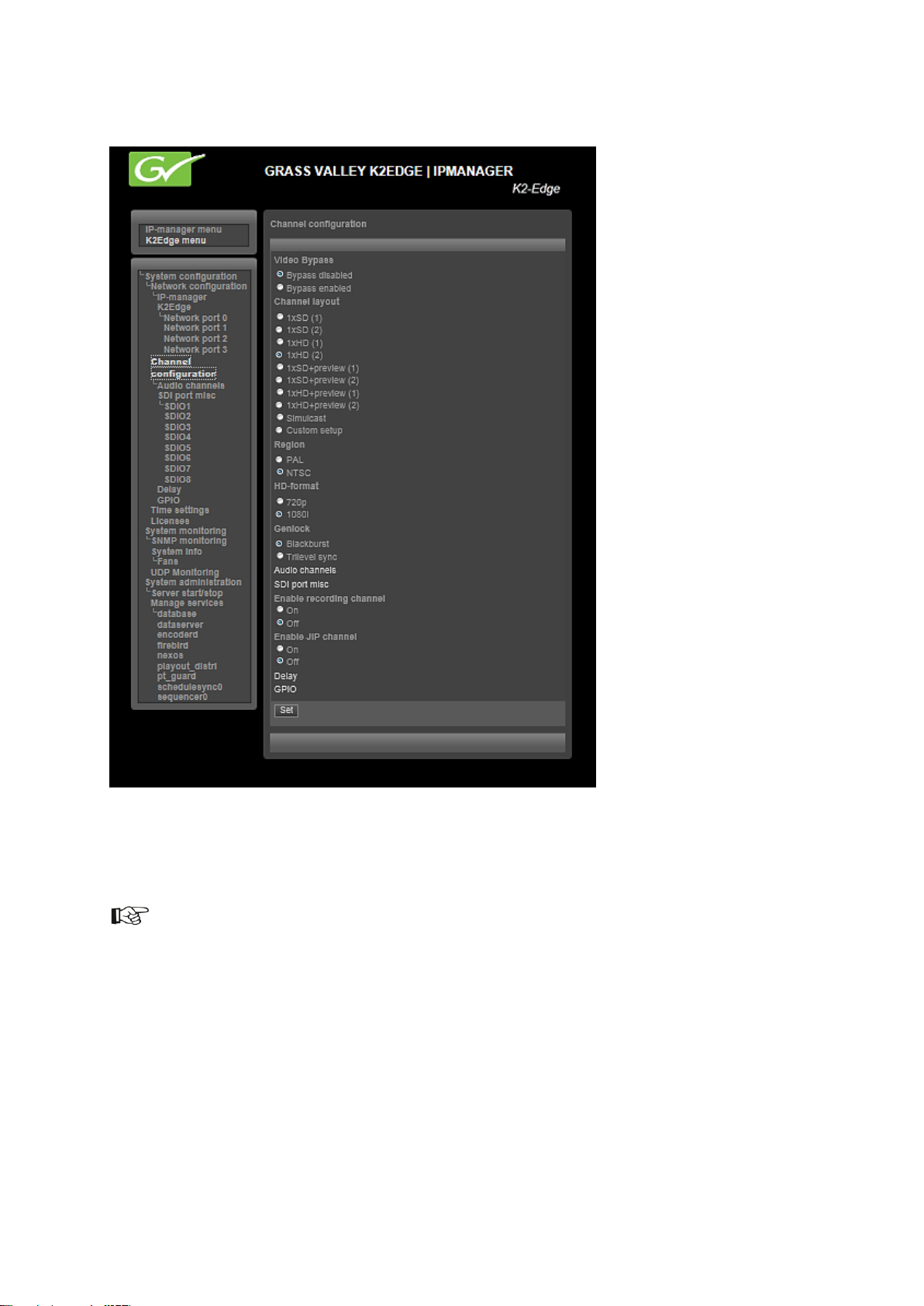
8.3 The IP Manager menu
Example IP Manager menu via the web browser. The system’s hostname is shown in the upper right
corner and on the web page’s tab. The highlighted menu item shows where you are in the navigation
tree.
To confirm changes, click Set.
Some changes in Channel settings require a restart of the nexos processes: select OK to set changes
and then Activate to activate changes.
K2 Edge User Manual - document version: 4.1 – Page 12
Page 13

8.4 System configuration > Network configuration
Hostname: the K2 Edge hostname
IP-manager: specify network settings for the IP Manager. Note that the IP Manager has its own
IP-address.
Use DHCP: On/Off
IP-address
Netmask
Gateway
Nameserver
K2Edge: specify network settings for the K2 Edge server
Network port <nr>
Method: Auto, using DHCP/Manual or Manual
IP-Address
Netmask
The system’s MAC address is displayed.
Gateway
Nameserver
TX/MAM server virtual IP: the TX/MAM servers’ virtual IP-address
8.5 System configuration > Channel configuration
Video Bypass: enable (activate) or disable the bypass
Channel layout: select one of the following presets:
1xSD (1) : single SD (with preset 1)
1xSD (2) : single SD (with preset 2)
1xHD (1) : single HD (with preset 1)
1xHD (2) : single HD (with preset 2)
1xSD+preview (1) : single SD + preview (preset 1)
1xSD+preview (2) : single SD + preview (preset 2)
1xHD+preview (1) : single HD + preview (preset 1)
1xHD+preview (2) : single HD + preview (preset 2)
Simulcast
Custom setup
Region: select PAL or NTSC
HD-format: for HD-channels, select 720p or 1080i
K2 Edge User Manual - document version: 4.1 – Page 13
Page 14

Genlock: select Blackburst or Trilevel sync
Audio channels: specify audio groups per SDIO
SDIO1-8:
Single audio group
Two audio groups
Three audio groups
Four audio groups
SDI port misc
SDIO in
VBI: Enabled/Disabled
HBI: Enabled/Disabled
SDIO out
Key/Fill
Enable recording channel: enable or disable the recording channel: On/Off
Enable JIP channel: enable or disable the JIP channel: On/Off
Delay: not used for the K2 Edge, only for VDS (Video Delay Server)
K2 Edge User Manual - document version: 4.1 – Page 14
Page 15

8.6 GPIO
Example.
Internal GPIO: DB9M
External GPIO: 410E
GPIO action: specify an action, for example GPI-5 switches to off
Use the pinning table to define conditionals for pins 1-8.
x: don't care (0 or 1)
0: low
1: high
Timecheat: check to enable cheat
type
None: results in no action
Script: runs a Linux shell script upon incoming GPIO commands, delayed by the configured delay
time if applicable.
Argument: script name preceded by the full path
Template: trigger a Composer template.
Argument: the template name which is configured in the channel pack
DB9M GPIO off: triggers a level on the specified GPIO bit, delayed by the configured delay
time if applicable.
Argument: GPI pin number
DB9M GPIO on: triggers a level on the specified GPIO bit, delayed by the configured delay time if
applicable.
Argument: GPI pin number
censor IO off: disables the censor on a SDI output port for the specified SDI port number
Argument: SDI port number (number only)
censor IO on: censors a SDI output port
Argument: SDI port number (number only)
K2 Edge User Manual - document version: 4.1 – Page 15
Page 16

Cheat delay: execute actions with an extra offset in hh:mm:ss:ff.
Note that cheat delays are only possible when in input mode.
Click Delete to delete a rule.
Click New rule to add a new rule.
Click Set to confirm.
8.7 System configuration > Time settings
Set the system date and time.
Current date: yyyy-mm-dd
Current time: hh:mm
8.8 System configuration > Licenses
Licenses are preconfigured.
8.9 System monitoring > System info
SNMP monitoring: not implemented yet
System info:
RAID partition free space (K)
Memory installed (MB)
CPU usage (percentage)
Non-running programs
Serial number and system installer version
PSU status
GPU Temperature (Celsius)
HD raid status
HD SMART status
HD temperature (Celsius)
Fans (speed in rotations per minute)
K2 Edge User Manual - document version: 4.1 – Page 16
Page 17

8.10 System monitoring > Fans
Displays fan speed in rounds per minute.
8.11 System monitoring > UDP Monitoring
UDP Monitoring: use this option to monitor Channel 0 (the single HD or SD Channel, or the HD
Channel in a simulcast setup) via IP. When enabled, a MPEG- transport stream with encoded
video, graphics, subtitles and audio (first stereo track) is sent over Ethernet using the UDPprotocol. A video player such as VLC is installed on a workstation to view output.
The UDP-monitoring option is described in more detail in the K2 Edge User Manual.
Resolution: 320x240/ 240x180/ 160x120
Aspect Ratio: 4:3/ 16:9
Video Bitrate: in kbit/s
Audio Enabled: On/Off
Audio Bitrate: in kbit/s
Ethernet Output: select On to enable monitoring and start streaming, Off to disable.
IP-address: IP-address of the target workstation (can be a multicast address)
IP-port: port the player will listen to. Default 4000
K2 Edge User Manual - document version: 4.1 – Page 17
Page 18

8.12 System administration
Server start/stop
Reboot
shutdown
Forced power off: only use when a shutdown is not possible.
Forced reset: only use when a Reboot is not possible.
Manage services
Services are:
database
dataserver
encoderd
firebird
nexos
playout_distri
pt_guard
schedulesync0
sequencer0
sequencer1
Options for each service are:
View the service’s version and status.
Start the service.
Stop the service.
Restart the service.
K2 Edge User Manual - document version: 4.1 – Page 18
Page 19

9 UDP monitoring
Use this option to monitor Channel 0 (the single HD or SD Channel, or the HD Channel in a simulcast
setup) via IP. When enabled, a MPEG- transport stream with encoded video, graphics, subtitles and
audio (first stereo track) is sent over Ethernet using the UDP-protocol. A video player such as VLC is
installed on a workstation to view output.
You need a license to enable the monitoring functionality.
Enable monitoring via the IP Manager > System monitoring > UDP Monitoring > Ethernet
Output: select On.
Settings:
Resolution: 320x240/ 240x180/ 160x120
Aspect Ratio: 4:3/ 16:9
Video Bitrate: in kbit/s
Audio Enabled: On/Off
Audio Bitrate: in kbit/s
Ethernet Output: select On to enable monitoring and start streaming, Off to disable.
IP-address: IP-address of the target workstation (can be a multicast address)
IP-port: port the player will listen to. Default 4000
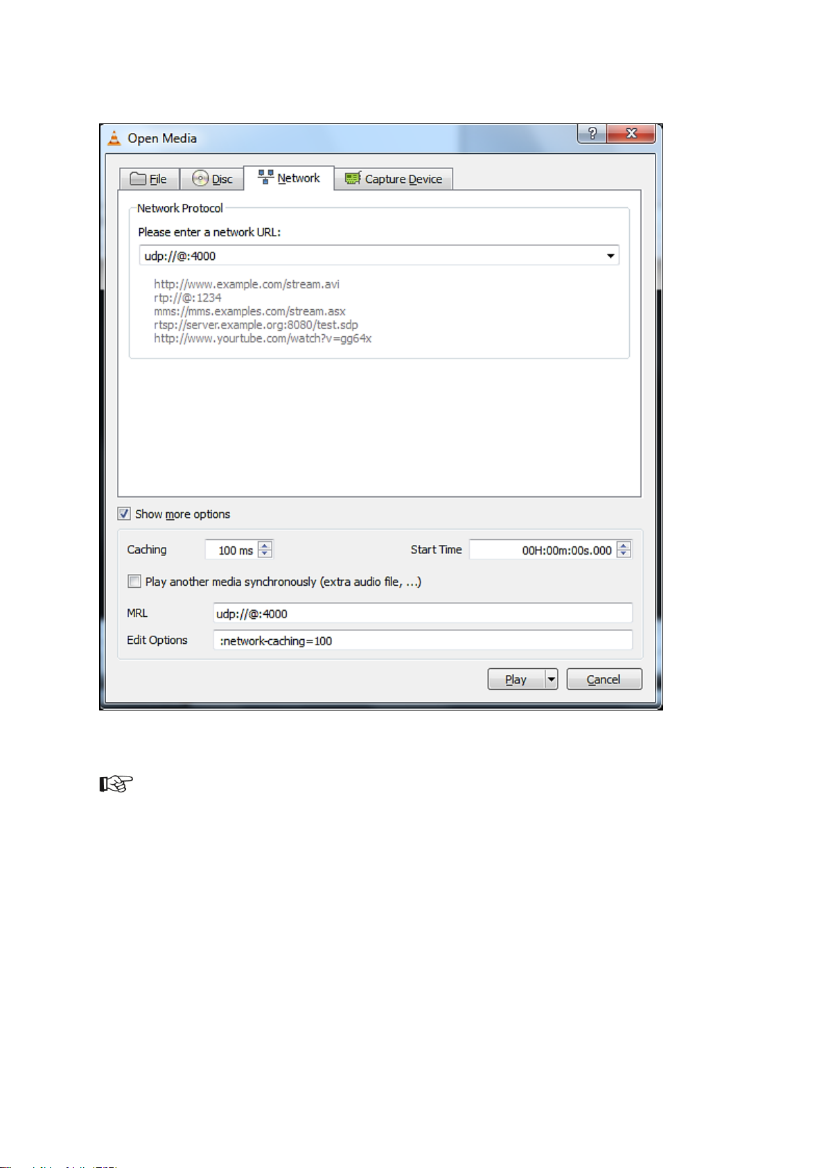
To receive the stream at the client, you can use a media player such as VLC
(http://www.videolan.org/vlc/) on a local workstation to view the video and audio content contained
within the mpeg transport stream:
Start the VLC-player.
Select Media > Open Network Stream > Network.
Enter the network URL: udp://@:XXXX, where XXXX = the IP-port specified in the IP
Manager.
If applicable select Show more options and set Caching to 100 ms.
Click Play to start streaming.
To receive streams from multiple K2 Edge servers, in the IP Manager configure a unique target IP-port
for each K2 Edge. For example if your client PC IP is 10.250.51.60, set up as:
K2 Edge1: 10.250.51.60:4000
K2 Edge2: 10.250.51.60:4001
K2 Edge3: 10.250.51.60:4002
K2 Edge User Manual - document version: 4.1 – Page 19
Page 20
Example.
To enable multicast delivery:
Verify with your network administrator that the routers in your network are multicast-enabled.
Verify with your network administrator which multicast addresses are available on the network.
In the IP Manager, specify the multicast destination IP-address available for network
monitoring.
K2 Edge User Manual - document version: 4.1 – Page 20
Page 21

10 Preview Channel
To set up the Preview Channel:
Configure the Preview Channel via the IP Manager presets [see chapter 7].
Define a preview Channel in TX/MAM as described in the Commissioning and TX/Mam User
Manuals.
in Channel Composer create a Format and Template to play out the clip and activate on the
Preview Channel.
An example channel Preview1 and Channel Pack are preconfigured.
K2 Edge User Manual - document version: 4.1 – Page 21
Page 22
11 Recording
With the K2 Edge Recording option you can record a Live input and ingest as an Asset. MXF file types
can be recorded.
What is needed:
A default Recording Channel is preconfigured: Record1.
To enable, you need the K2-EDGE-SWLX-REC license.
You need the RecPack Channel Pack to work with the Recording function. The RecPack
Channel must be activated on the Recording Channel.
Enable recording via the IP Manager.
How to:
Enable recording via the IP Manager > Channel configuration > Enable recording channel:
select On.
Create a temporary Playlist. This Playlist is used to schedule Events with the recording
Formats attached.
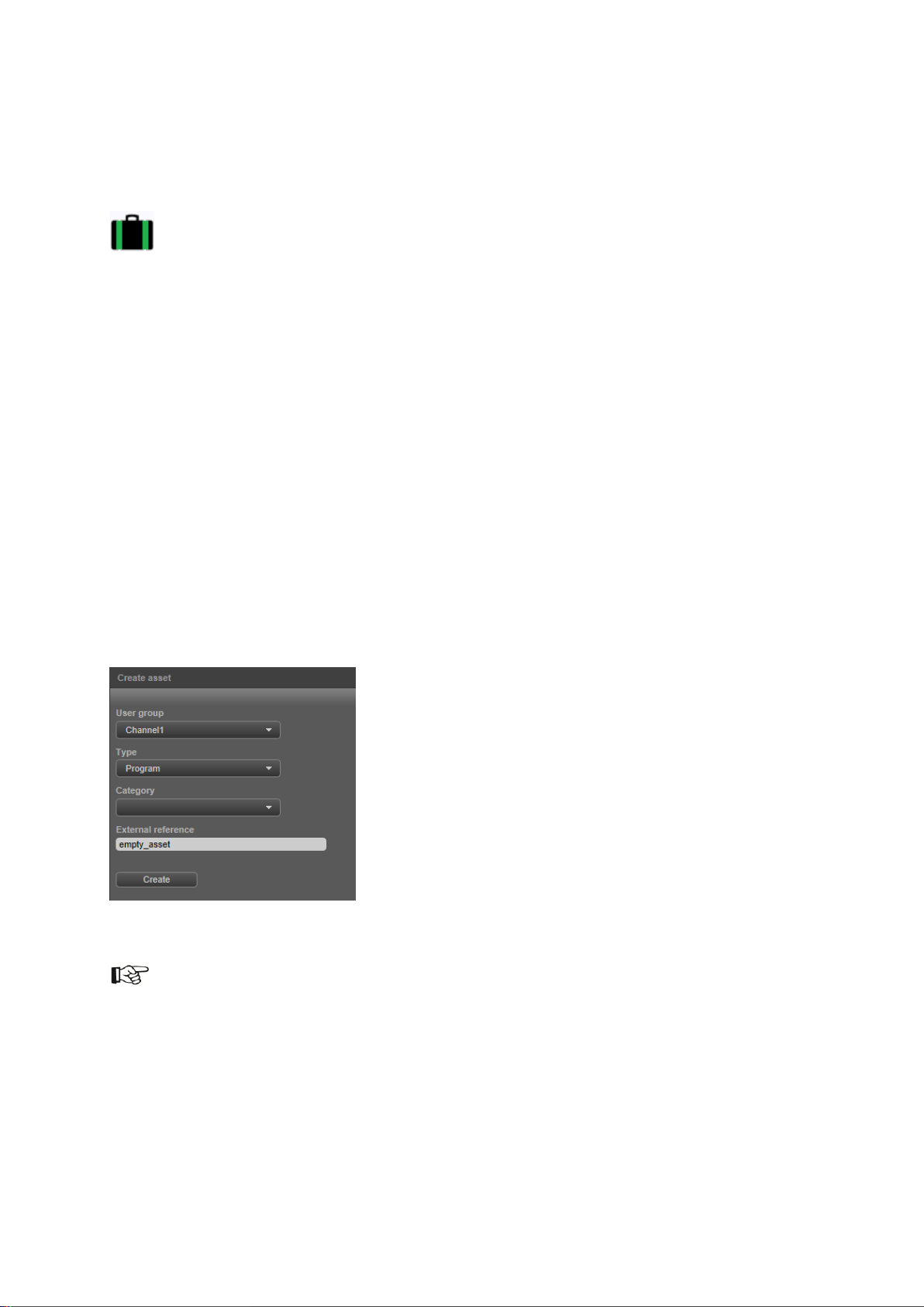
In TX/MAM, create an empty Asset of the appropriate Asset Type.
Example.
You can also overwrite an existing Asset. In that case, in the LiveRecord Format set the StartLiveRec
> overwrite and CheckLiveAssetStatus > Overwrite options to 1.
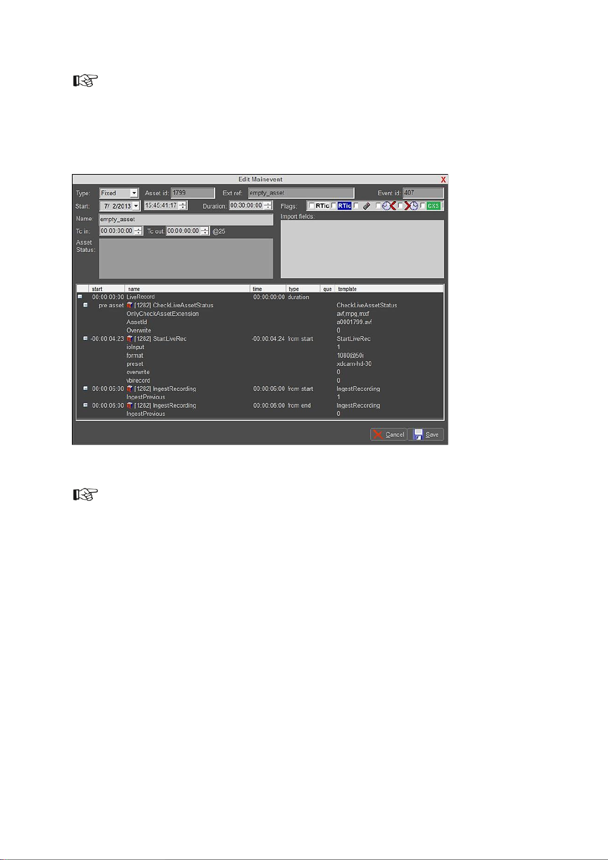
Drag the (empty) Asset into a temporary Playlist and attach the LiveRecord Format to the
Event.
Double-click the Event and specify Duration. You do not have to specify an Event Tc in / Tc
out.
K2 Edge User Manual - document version: 4.1 – Page 22
Page 23
You can also specify the Asset’s duration in TX/MAM, on the Spotcheck tab > Duration.
Activate the Event to the Record Channel, to the appropriate start date and time.
Make sure the LiveRec Channel Pack is activated on the Record Channel.
Example Recording Event.
If you do not know the recording Event’s duration in advance, schedule a LiveRecord Event
with a Duration that exceeds the estimated duration.
Schedule a manual Event after the recording Event with the IngestOnly Format attached;
recording will be stopped when the manual Event is triggered and the recording Event’s
duration is overruled. The IngestOnly Event ingests the recording.
K2 Edge User Manual - document version: 4.1 – Page 23
Page 24
Pre-check OK.
Recording will not start. The file already exists (and overwrite is not enabled), or the file extension
not allowed.
Recording OK.
Recording error.
Ingest successfully finished.
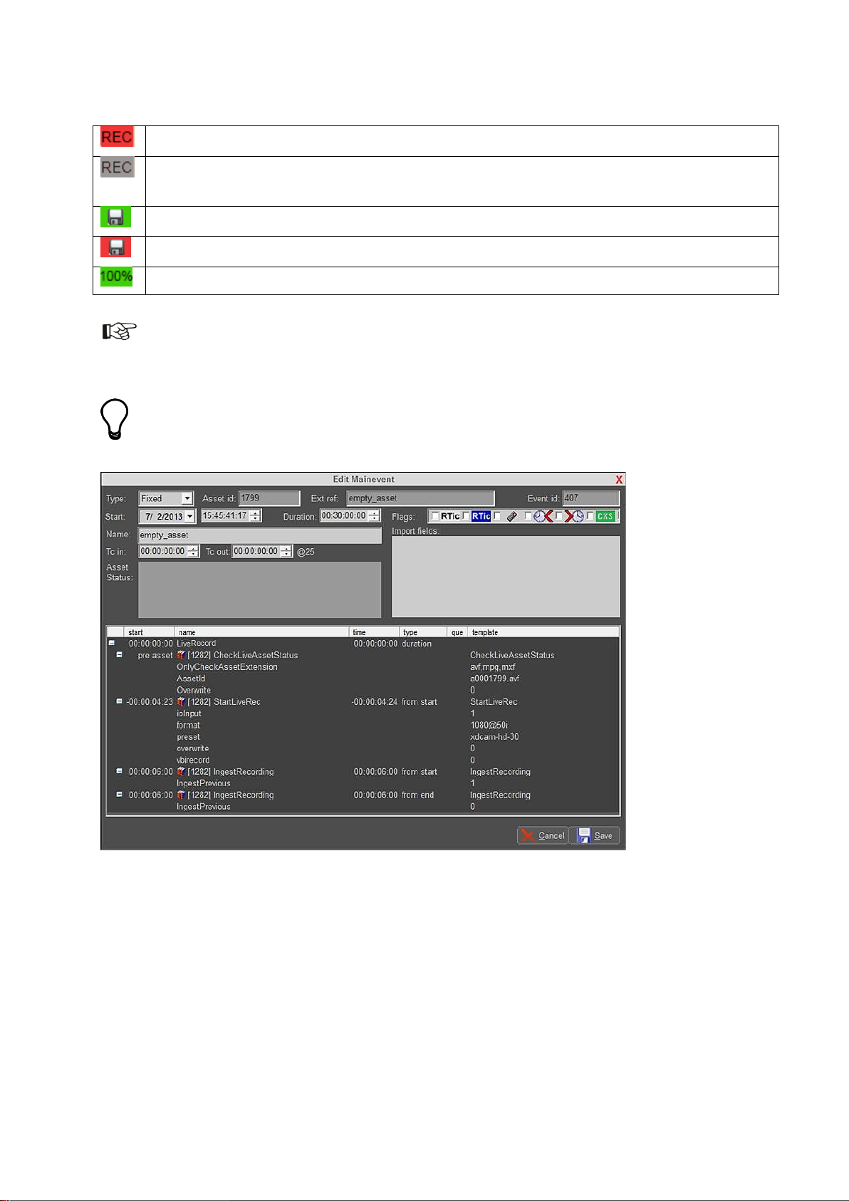
In Playout Control (POC), the Flag column shows following status indicators:
After ingest, Assets can be shared and exported via the TX/MAM Sharing tab and Export options.
The LiveRecord Format
Example Event in POC.
CheckLiveAssetStatus: a check performed before recording starts. Verifies:
o allowed file extensions
o if the Asset ID exists in TX/MAM
o contains the Overwrite option (0 overwrite is not allowed, 1 is allowed)
StartLiveRec: sends the recording command to nexos, default 6 seconds prior to start.
K2 Edge User Manual - document version: 4.1 – Page 24
Page 25

o ioInput: specifies the input port that is recorded. Numbering starts at 1; IO1 is 1, IO2 is
2, etcetera.
o format: the broadcast format
PAL
720@50p
1080@50i
NTSC
720@5994p
1080@5994i
o preset: the encoding preset, determines amongst others the container/codec
o mxf-d10-<bitrate>
Use for SD.
bitrate: 30/40/50
o xdcam-hd-<bitrate>
Use for HD.
bitrate: 30/40/50
o overwrite: 0 overwrite is not allowed, 1 is allowed
o vbirecord: 0 do not include vbi info, 1 include vbi info. Only supported for PAL-formats.
VBI is recorded in the visual area.
IngestRecording: starts ingesting the previous recording, if any, 6 seconds from start. Starts
ingesting the current recording, 6 seconds from end.
Event parameters can be modified in POC. If you want to work with different parameters than the ones
predefined, to avoid having to change parameters for each recording we advise to change the Format
in Channel Composer.
K2 Edge User Manual - document version: 4.1 – Page 25
Page 26

The IngestOnly Format
Example Event in POC.
This Format stops recording when the Event is triggered.
Ingests the previous recording.
K2 Edge User Manual - document version: 4.1 – Page 26
Page 27

12 Configuring time settings
Preferably a LTC-signal (Linear Timecode) is used to synchronize time codes. If this is not possible,
other options are:
NTP sync (Network Time Protocol) to a NTP- server.
Free running (system uses an internal clock)
12.1 Setting up NTP
Edit /system/objects/code/setdate
NTPSERVER: specify the NTP-server's IP-address
ZONE: specify time zone [see options below], the ZONE-setting determines offset relative to
CET/GMT.
To test settings, from Linux command line enter:
/system/objects/code]# setdate -ntp [enter]
If settings are incorrect, an error message will be displayed.
To ensure that time is regularly synced, edit /etc/crontab. Remove the "#" in front of the line:
#00 * * * * root /system/objects/code/setdate -ntp >/dev/null 2>&1
Result:
00 * * * * root /system/objects/code/setdate -ntp >/dev/null 2>&1
K2 Edge User Manual - document version: 4.1 – Page 27
Page 28

Example:
...code]# ./setdate -m 07/29/08 11:37:47 [enter]
Explanation:
-m = manual
07 = month
29 = day of month
08 = year
11 = hours
37 = minutes
47 = seconds
12.2 Configuring time manually
To set the date, log in via putty (ssh) as user root.
Go to the /system/objects/code folder:
...code]# cd /system/objects/code [enter]
Execute script setdate, use the –help option for an explanation:
...code]# ./setdate –help [enter]
To request the date from the NTP server configured in setdate:
...code]# ./setdate -ntp [enter]
ZONE options are listed on the next pages.
Options listed below are case sensitive.
Insert a “/” sign behind continent names.
Place ZONE names between quotes.
Example: “Europe/Amsterdam”
K2 Edge User Manual - document version: 4.1 – Page 28
Page 29

CET
CST6CDT
Cuba
EET
EST
EST5EDT
Egypt
Eire
Factory
GB
GB-Eire
GMT
GMT+0
GMT-0
GMT0
Greenwich
HST
Hongkong
Iceland
Iran
Israel
Jamaica
Japan
Kwajalein
Libya
MET
MST
MST7MDT
NZ
NZ-CHAT
Navajo
PRC
PST8PDT
Poland
Portugal
ROK
Singapore
Turkey
UCT
UTC
Universal
W-SU
WET
Zulu
iso3166.tab
posixrules
zone.tab
Africa/
Abidjan
Accra
Addis_Ababa
Algiers
Asmara
Asmera
Bamako
Bangui
Banjul
Bissau
Blantyre
Brazzaville
Bujumbura
Cairo
Casablanca
Ceuta
Conakry
Dakar
Dar_es_Salaam
Djibouti
Douala
El_Aaiun
Freetown
Gaborone
Harare
Johannesburg
Kampala
Khartoum
Kigali
Kinshasa
Lagos
Libreville
Lome
Luanda
Lubumbashi
Lusaka
Malabo
Maputo
Maseru
Mbabane
Mogadishu
Monrovia
Nairobi
Ndjamena
Niamey
Nouakchott
Ouagadougou
Porto-Novo
Sao_Tome
Timbuktu
Tripoli
Tunis
Windhoek
America/
Adak
Anchorage
Anguilla
Antigua
Araguaina
Argentina
Aruba
Asuncion
Atikokan
Atka
Bahia
Barbados
Belem
Belize
Blanc-Sablon
Boa_Vista
Bogota
Boise
Buenos_Aires
Cambridge_Bay
Campo_Grande
Cancun
Caracas
Catamarca
Cayenne
Cayman
Chicago
Chihuahua
Coral_Harbour
Cordoba
Costa_Rica
Cuiaba
Curacao
Danmarkshavn
Dawson
Dawson_Creek
Denver
Detroit
Dominica
Edmonton
Eirunepe
El_Salvador
Ensenada
Fort_Wayne
Fortaleza
Glace_Bay
Godthab
K2 Edge User Manual - document version: 4.1 – Page 29
Page 30

Goose_Bay
Grand_Turk
Grenada
Guadeloupe
Guatemala
Guayaquil
Guyana
Halifax
Havana
Hermosillo
Indiana
Indianapolis
Inuvik
Iqaluit
Jamaica
Jujuy
Juneau
Kentucky
Knox_IN
La_Paz
Lima
Los_Angeles
Louisville
Maceio
Managua
Manaus
Martinique
Mazatlan
Mendoza
Menominee
Merida
Mexico_City
Miquelon
Moncton
Monterrey
Montevideo
Montreal
Montserrat
Nassau
New_York
Nipigon
Nome
Noronha
North_Dakota
Panama
Pangnirtung
Paramaribo
Phoenix
Port-au-Prince
Port_of_Spain
Porto_Acre
Porto_Velho
Puerto_Rico
Rainy_River
Rankin_Inlet
Recife
Regina
Rio_Branco
Rosario
Santiago
Santo_Domingo
Sao_Paulo
Scoresbysund
Shiprock
St_Johns
St_Kitts
St_Lucia
St_Thomas
St_Vincent
Swift_Current
Tegucigalpa
Thule
Thunder_Bay
Tijuana
Toronto
Tortola
Vancouver
Virgin
Whitehorse
Winnipeg
Yakutat
Yellowknife
Antarctica/
Casey
Davis
DumontDUrville
Mawson
McMurdo
Palmer
Rothera
South_Pole
Syowa
Vostok
Arctic/
Longyearbyen
Asia/
Aden
Almaty
Amman
Anadyr
Aqtau
Aqtobe
Ashgabat
Ashkhabad
Baghdad
Bahrain
Baku
Bangkok
Beijing
Beirut
Bishkek
Brunei
Calcutta
Choibalsan
Chongqing
Chungking
Colombo
Dacca
Damascus
Dhaka
Dili
Dubai
Dushanbe
Gaza
Harbin
Hong_Kong
Hovd
Irkutsk
Istanbul
Jakarta
Jayapura
Jerusalem
Kabul
Kamchatka
Karachi
Kashgar
Katmandu
Krasnoyarsk
Kuala_Lumpur
Kuching
Kuwait
Macao
Macau
Magadan
Makassar
Manila
Muscat
Nicosia
K2 Edge User Manual - document version: 4.1 – Page 30
Page 31

Novosibirsk
Omsk
Oral
Phnom_Penh
Pontianak
Pyongyang
Qatar
Qyzylorda
Rangoon
Riyadh
Riyadh87
Riyadh88
Riyadh89
Saigon
Sakhalin
Samarkand
Seoul
Shanghai
Singapore
Taipei
Tashkent
Tbilisi
Tehran
Tel_Aviv
Thimbu
Thimphu
Tokyo
Ujung_Pandang
Ulaanbaatar
Ulan_Bator
Urumqi
Vientiane
Vladivostok
Yakutsk
Yekaterinburg
Yerevan
Atlantic/
Azores
Bermuda
Canary
Cape_Verde
Faeroe
Faroe
Jan_Mayen
Madeira
Reykjavik
South_Georgia
St_Helena
Stanley
Australia/
ACT
Adelaide
Brisbane
Broken_Hill
Canberra
Currie
Darwin
Eucla
Hobart
LHI
Lindeman
Lord_Howe
Melbourne
NSW
North
Perth
Queensland
South
Sydney
Tasmania
Victoria
West
Yancowinna
Brazil/
Acre
DeNoronha
East
West
Canada/
Atlantic
Central
East-Saskatchewan
Eastern
Mountain
Newfoundland
Pacific
Saskatchewan
Yukon
Chile/
Continental
EasterIsland
Etc/
GMT
GMT+0
GMT+1
GMT+10
GMT+11
GMT+12
GMT+2
GMT+3
GMT+4
GMT+5
GMT+6
GMT+7
GMT+8
GMT+9
GMT-0
GMT-1
GMT-10
GMT-11
GMT-12
GMT-13
GMT-14
GMT-2
GMT-3
GMT-4
GMT-5
GMT-6
GMT-7
GMT-8
GMT-9
GMT0
Greenwich
UCT
UTC
Universal
Zulu
Europe/
Amsterdam
Andorra
Athens
Belfast
Belgrade
Berlin
Bratislava
Brussels
Bucharest
Budapest
Chisinau
Copenhagen
Dublin
K2 Edge User Manual - document version: 4.1 – Page 31
Page 32

Gibraltar
Guernsey
Helsinki
Isle_of_Man
Istanbul
Jersey
Kaliningrad
Kiev
Lisbon
Ljubljana
London
Luxembourg
Madrid
Malta
Mariehamn
Minsk
Monaco
Moscow
Nicosia
Oslo
Paris
Podgorica
Prague
Riga
Rome
Samara
San_Marino
Sarajevo
Simferopol
Skopje
Sofia
Stockholm
Tallinn
Tirane
Tiraspol
Uzhgorod
Vaduz
Vatican
Vienna
Vilnius
Volgograd
Warsaw
Zagreb
Zaporozhye
Zurich
Indian/
Antananarivo
Chagos
Christmas
Cocos
Comoro
Kerguelen
Mahe
Maldives
Mauritius
Mayotte
Reunion
Mexico/
BajaNorte
BajaSur
General
Mideast/
Riyadh87
Riyadh88
Riyadh89
Pacific/
Apia
Auckland
Chatham
Easter
Efate
Enderbury
Fakaofo
Fiji
Funafuti
Galapagos
Gambier
Guadalcanal
Guam
Honolulu
Johnston
Kiritimati
Kosrae
Kwajalein
Majuro
Marquesas
Midway
Nauru
Niue
Norfolk
Noumea
Pago_Pago
Palau
Pitcairn
Ponape
Port_Moresby
Rarotonga
Saipan
Samoa
Tahiti
Tarawa
Tongatapu
Truk
Wake
Wallis
Yap
US/
Alaska
Aleutian
Arizona
Central
East-Indiana
Eastern
Hawaii
Indiana-Starke
Michigan
Mountain
Pacific
Samoa
K2 Edge User Manual - document version: 4.1 – Page 32
Page 33

FTP
Default port 20 and 21
SSH/SCP
Default port 22
Cobalt database access
Default port 5020
Webbased interface
Default port 80 on IP manager network/IP
ptsockse
Default port 5000
nexos complex socket
Default port 5001
UDP-monitoring
Default port 4000
13 K2 Edge network ports
K2 Edge User Manual - document version: 4.1 – Page 33
Page 34
14 K2 Edge IOs
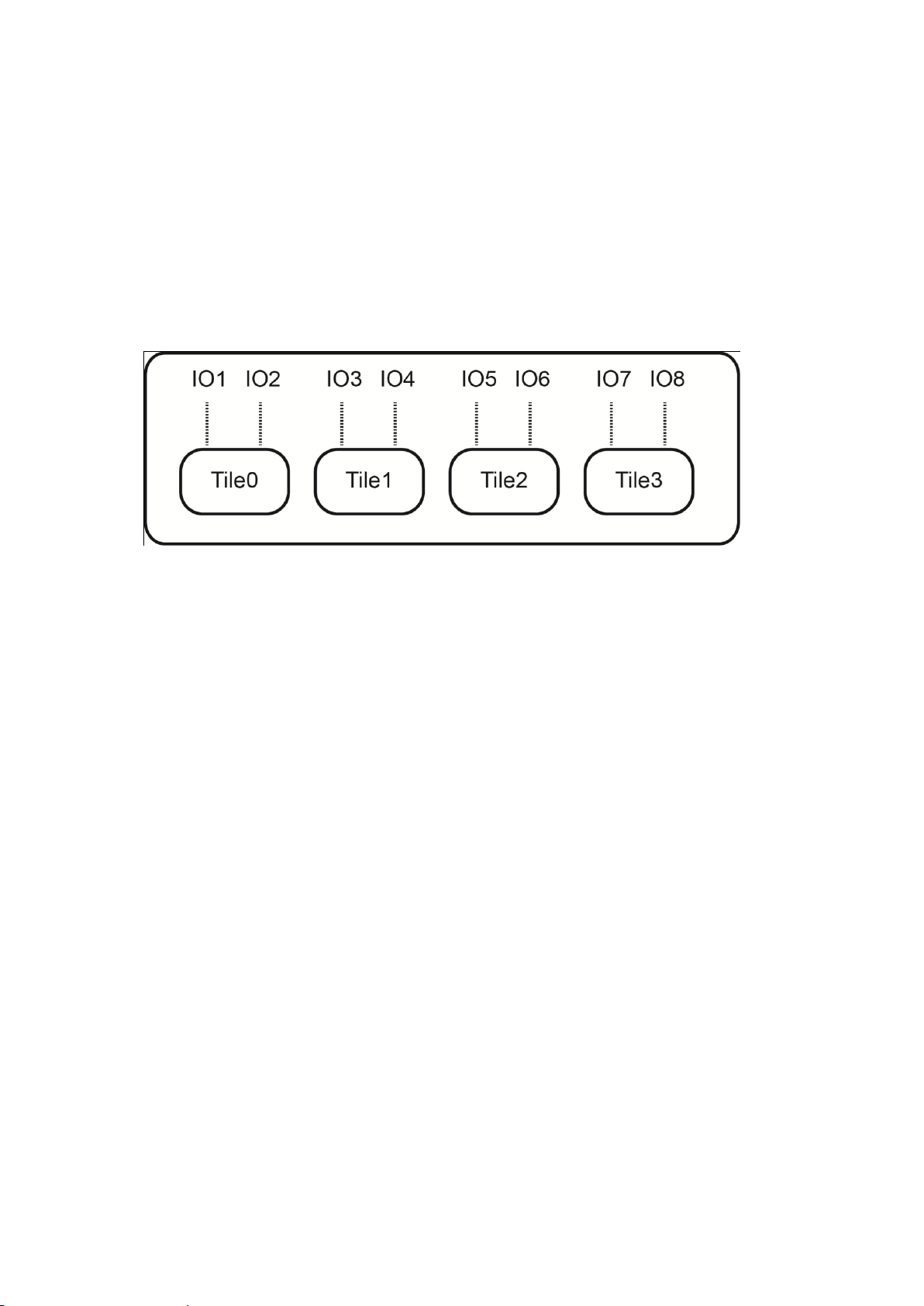
14.1 Tiles
De K2 Edge contains 8 bidirectional SDI-ports. One video format can be configured per tile.
IO1 is always configured as input and IO2 as output to be able to use the bypass relay. A
number of presets have been defined for the K2 Edge. These presets are selected via the IP
Manager.
IOs and tiles.
14.2 Bypass
Ports IO1 (input) and IO2 (output) can be internally connected to bypass a Channel. When set
to bypass, the signal of the main Channel is ignored, and instead the feed received at IO1 is
made available at IO2. Bypass is enabled via the IP Manager.
14.3 Master and Slaves
To make a Channel's signal available on several SDI-outputs, one or more of the IO-ports can
be configured to become slave outputs. By default, the signal provided by a slave output is an
exact copy of the master output signal. A slave output uses the properties of the master
Output it refers to, and thus cannot introduce another broadcast format for the same Channel.
14.4 Genlock
If enabled, the SDI-output synchronizes to the frame rhythm of the genlock (blackburst) signal
connected to the blackburst BNC-socket on the back of the server. If disabled, or when no
genlock signal can be detected, the output will synchronize to an internal clock. Genlock can
only be set for master outputs.
K2 Edge User Manual - document version: 4.1 – Page 34
Page 35

15 Cross Conversion
15.1 Introduction
From release 4.1 K2 Edge supports cross conversion between different broadcast signals.
This means that the system is capable of transforming a broadcast signal from one type
towards another. For example, a playout system renders and broadcasts a 720@59.94p
signal. When using a live-input of type NTSC the K2 Edge will detect that the input and output
formats are not compatible (but related) and will automatically insert a cross conversion filter.
This cross conversion filter will deinterlace/interlace the frames and correct the frame rate.
Cross conversion is automatically applied to clips, SDI-feeds and animations as indicated in
the tables in chapter 15.2.
A number of services embedded in clips and in the VBI-data in SDI-streams, such as AFD,
ATC and CDP, are extracted from the input source and made available in the output, possibly
converted to a suitable alternative format (for example ATC and VITC).
K2 Edge User Manual - document version: 4.1 – Page 35
Page 36

PAL
SD, 720x576, interlaced, 25 frames/sec, AR 4:3
Accepted input
media formats
Fram
e
rate1
Conversions
Comments
PAL
25
None
Native format.
720@50p
50
AR, Cross, Down
Different (but related) frame rate, automatically cross
converted from a progressive to an interlaced format. This
includes conversion of a selected set of services. Video is
scaled down via a Channel Composer template.
1080@50i
25
AR, Down
Close to native format in terms of video and audio, just
more pixels. Video is scaled down via a Channel
Composer template.
NTSC
SD, 720x480, interlaced, 29.97 frames/sec, AR 4:3
Accepted input
media formats
Fram
e rate
Conversions
Comments
NTSC
29.97
None
Native format.
720@5994p
59.94
AR, Cross, Down
Different (but related) frame rate, automatically cross
converted from progressive to interlaced format. This
includes conversion of a selected set of services. Video is
scaled down via a Channel Composer template.
1080@5994i
29.97
AR, Down
Close to native format in terms of video and audio, just
more pixels. Video is scaled down via a Channel
Composer template.
15.2 Supported broadcast formats
The following tables define the K2 Edge supported broadcast formats with their related
supported input media formats. For all of these tables we recognize the following conversion
types:
AR – Aspect Ratio conversion. Under user control via Channel Composer template.
Cross – Cross conversion between formats with different but related frame rates,
converting from interlaced to progressive format or vice versa. Fully automatic.
Down – Downscale of larger video format to fit smaller broadcast format. Under user
control via Channel Composer template.
Up – Upscale of smaller video format to fit larger broadcast format. Under user
control via Channel Composer template.
1
Frame rate for all tables is in frames per second.
K2 Edge User Manual - document version: 4.1 – Page 36
Page 37

720@50p
HD, 1280x720, progressive, 50 frames/sec, AR 16:9
Accepted input
media formats
Fram
e rate
Conversions
Comments
PAL
25
AR, Cross, Up
Different (but related) frame rate, and automatically cross
converted from an interlaced to a progressive format. This
includes conversion of a selected set of services. Video is
scaled up via a Channel Composer template.
720@50p
50
None
Native format.
1080@50i
25
Cross, Down
Different (but related) frame rate, and automatically cross
converted from interlaced to progressive format. This
includes conversion of a selected set of services. Video is
scaled down via a Channel Composer template.
720@5994p
HD, 1280x720, progressive, 59.94 frames/sec, AR 16:9
Accepted input
media formats
Fram
e rate
Conversions
Comments
NTSC
29.97
AR, Cross, Up
Different (but related) frame rate, and automatically cross
converted from an interlaced to a progressive format. This
includes conversion of a selected set of services. Video is
scaled up via a Channel Composer template.
720@5994p
59.94
None
Native format.
1080@5994i
29.97
Cross, Down
Different (but related) frame rate, and automatically cross
converted from interlaced to progressive format. This
includes conversion of a selected set of services. Video is
scaled down via a Channel Composer template.
1080@50i
HD, 1920x1080, interlaced, 25 frames/sec, AR 16:9
Accepted input
media formats
Fram
e rate
Conversions
Comments
PAL
25
AR, Up
Close to native format in terms of video and audio, just
less pixels. Video is scaled up via a Channel Composer
template.
720@50p
50
Cross, Up
Different (but related) frame rate, automatically cross
converted from progressive to interlaced format. This
includes conversion of a selected set of services. Video is
scaled up via a Channel Composer template.
1080@50i
25
None
Native format.
K2 Edge User Manual - document version: 4.1 – Page 37
Page 38

1080@5994
i
HD, 1920x1080, interlaced, 29.97 frames/sec, AR 16:9
Accepted input
media formats
Fram
e rate
Conversions
Comments
NTSC
29.97
AR, Up
Close to native format in terms of video and audio, but
less pixels. Video is scaled up via a Channel Composer
template.
720@5994p
59.94
Cross, Up
Different (but related) frame rate, automatically cross
converted from progressive to interlaced format. This
includes conversion of a selected set of services. Video is
scaled up via a Channel Composer template.
1080@5994i
29.97
None
Native format.
Input source
Condition
1
AFD-objects defined on the timeline of a Channel Composer template.
2
AFD ANC packets found in an MXF file, embedded in accordance with the SMPTE
436M-2006 specification, section 6: MXF Ancillary Data Packet wrapping
specifications.
Main Player (*)
3
AFD-objects found embedded in the VBI-section of an SDI-stream of all supported
broadcast formats.
Main Player
15.3 Service extraction
A number of services embedded in clips and in the VBI-data in SDI-streams are extracted
from the input source and made available in the output, possibly converted to a suitable
alternative format. These extracted services will survive cross conversion, although some of
the conversions are lossy.
The following sections describe each of the services recognized by the extraction process,
with a list of the recognized sources.
15.3.1 AFD
The following input sources are supported for extraction of the Active Format Description
(AFD) service, in given order of priority:
(*) Input sources with the main Player condition are only recognized when the associated
Channel Composer Player object was assigned the main player role. At any given time, only
one Player can have this role.
K2 Edge User Manual - document version: 4.1 – Page 38
Page 39

Input source
Condition
1
A STL subtitle rendered in CEA-608 format. The 608 subtitle data will end up in the
CDP’s embedded 608 section.
This input source can co-exist with the next #2 source.
This input can also co-exist with #3 and #5. If present, 608 subtitle data from #3
and #5 will be overwritten.
2
CEA-608 XDS commands placed on the timeline of a Channel Composer template.
The XDS data will end up in the CDP’s embedded 608 section.
This input source can co-exist with the previous #1 source.
This input can also co-exist with #3 and #5. If present, 608 XDS data from #3 and
#5 will be overwritten.
3
CDP objects found embedded in VBI section of an incoming SDI stream.
Main Player
4
CDP objects created from CEA-608 metadata as a result of cross conversion from
SD to HD format. See the CEA-608 section below on how the 608 metadata came
into existence in the first place.
Main Player
5
CDP ANC packets found in an MXF file, embedded conform the SMPTE 436M2006 specification, section 6: MXF Ancillary Data Packet wrapping specifications.
Main Player
Input source
Condition
1
Any clip. The time code represents clip time.
Main Player
2
ATC objects found embedded in VBI section of HD SDI stream.
Main Player
15.3.2 CDP
The following input sources are supported for extraction of the Caption Distribution Packet
(CDP) service, in given order of priority:
15.3.3 ATC / VITC
The following input sources are supported for extraction of the Ancillary Time Code (ATC) and
Vertical Interval Time Code (VITC) services, in given order of priority:
That is, the ATC/VITC output reflects the time code of either the currently playing clip (if
playing with main player role) or the currently playing SDI stream (again, only if playing as
main player).
The extracted time code is emitted as VITC for SD-channels and ATC for HD channels.
K2 Edge User Manual - document version: 4.1 – Page 39
Page 40

Input source
Condition
1
An STL subtitle rendered in CEA-608 format.
This input source can co-exist with the next #2 source.
2
CEA-608 XDS commands placed on the timeline of a Channel Composer template.
This input source can co-exist with the previous #1 source.
3 CEA-608 objects found embedded in VBI section of an incoming SDI stream in
NTSC broadcast format.
Main Player
4
CEA-608 objects created from CDP metadata as a result of cross conversion from
HD to SD format.
Main Player
15.3.4 CEA-608
The following input sources are supported for extraction of the CEA-608 closed caption
service, in given order of priority:
15.4 The main Player
15.4.1 Introduction
In Channel Composer, Objects such as ‘Clip’, ‘Audio’ and ’Still’ use a Player to play out
content. Players can be used to control playout. Different actions can be defined. The default
is: Play. Players can be modified in the Object and Objects window.
One main Player can be active per Channel.
The main Player role has following properties:
The main Player has priority over other Players when resources are assigned.
If the main Player contains an embedded Closed Caption subtitle stream, this stream
will be played out. If other Clips contain subtitle streams, these streams will not be
played out. In other words, only the main Player’s subtitle stream will be played out.
The main Player is the source for the ATC (HD) or VITC (SD) timecode signal in the
SDI-output. Only one signal can be sent out, i.e. from the main Player.
If the main Player is a Live Player and this Player transfers VBI-data from the SDI-
input, this VBI-data will be transferred to SDI-out instead of any VBI-data generated
by the K2 Edge server. This means that VBI-data from the input such as subtitles and
teletext is passed to the output 'as is'.
The main Player role can be assigned at any point in time, but is only active if
between an In and Out Point.
K2 Edge User Manual - document version: 4.1 – Page 40
Page 41

15.4.2 How to
In Channel Composer, the main Player command is automatically added for the first Clip or
Live Object that is added to a Template.
To manually set the main Player:
In Channel Composer, go to Library > Command and select the Set Main Player
icon.
Drag on the Template Timeline, on the appropriate template and time.
The Set Main Player icon is added to the timeline .
Double-click the Set Main Player icon and in its Object window, select the
appropriate Player.
Example Pick a Player window in Channel Composer.
K2 Edge User Manual - document version: 4.1 – Page 41
Page 42

LTC - DB9M
LTC_out
+ (positive) pin 2
LTC_out
- (negative) pin 4
LTC_out GND
GND ground) pin 1
LTC_in
+ (positive) pin 7
LTC_in
- (negative) pin 8
LTC_in GND
GND (ground) pin 9
GPIO - DB9M
GPI0 pin 1
GPI1 pin 2
GPI2 pin 3
GPI3 pin 4
GPI4 pin 5
GPI5 pin 6
GPI6 pin 7
GPI7 pin 8
GND pin 9
16 GPIO
16.1 GPIO and LTC pinning
Internal GPIO: DB9M
External GPIO: 410E
GPIO is an open collector port.
K2 Edge User Manual - document version: 4.1 – Page 42
Page 43

16.2 GPIO via the IP Manager
Define GPIO events via the IP Manager web interface to trigger events or templates on the
K2Edge when a GPI is coming in.
Example.
IP Manager web interface > Channel Configuration > GPIO
GPIO action: specify an action, for example GPI-5 switches to off
Use the pinning table to define conditionals for pins 1-8.
x: don't care (0 or 1)
0: low
1: high
Timecheat: check to enable cheat
type
None: results in no action
Script: runs a Linux shell script upon incoming GPIO commands, delayed by the
configured delay time if applicable.
Argument: script name preceded by the full path
Template: trigger a Composer template.
Argument: the template name which is configured in the channel pack
DB9M GPIO off: triggers a level on the specified GPIO bit, delayed by the configured
delay time if applicable.
Argument: GPI pin number
K2 Edge User Manual - document version: 4.1 – Page 43
Page 44

Options
Max
Used
Clips
4
1 - clouds video
w/squeeze back
Live inputs
4
2 - PGM/LIVE each w/3D
Squeeze back
Static graphics
NL
2 - backgrounds for text
crawls
Animated graphics
NL
2 - logos w/tilt
Crawls & Tickers
NL
2 - text crawls
Text
NL
3
2D DVE
NL
1 - Squeeze back of
clouds clip
3D DVE
NL
4 - Squeeze back of 2
PGM/LIVE and DVE for
logos
Audio (mono) tracks
16 4 Voice overs
NL
1
DB9M GPIO on: triggers a level on the specified GPIO bit, delayed by the configured
delay time if applicable.
Argument: GPI pin number
censor IO off: disables the censor on a SDI output port for the specified SDI port
number
Argument: SDI port number (number only)
censor IO on: censors a SDI output port
Argument: SDI port number (number only)
Cheat delay: execute actions with an extra offset in hh:mm:ss:ff.
Note that cheat delays are only possible when in input mode.
Click Delete to delete a rule.
Click New rule to add a new rule.
Click Set to confirm.
17 Capabilities
Capabilities depend on licenses required.
K2 Edge User Manual - document version: 4.1 – Page 44
Page 45

10.250.51.51 MAIN-DB
project_options.serverip = "10.250.51.51"
ingest.assetHostIp = "10.250.51.51"
18 Appendix: Changing an IP-address
After changing the playout nodes’, TX/MAM or FTP-servers’ IP-address, following
adjustments need to be made:
18.1 After changing the IP-address of the playout nodes
1) Change the playout node’s IP-address in the TX/MAM Channel settings.
18.2 After changing the virtual IP-address of the TX/MAM-servers
1) On the K2Edge nodes, in /etc/hosts adjust MAIN-DB. Specify the virtual IP of the
TX/MAM servers.
Example:
You can also set the IP-address of the TX/MAM server via the IP Manager.
2) On both the TX/MAM servers, in /usr/local/apache2/application/configs/txmam.ini,
adjust project_options.serverip. Specify the virtual IP of the TX/MAM servers.
Example:
3) On both the TX/MAM servers, in /usr/local/apache2/application/configs/txmam.ini,
adjust ingest.assetHostIp. Specify the virtual IP of the TX/MAM servers.
Example:
4) To change the IP-address in the POC desktop shortcut properties
Right-click the POC icon on your desktop > Properties > Shortcut.
In the Target field fill in the TX/MAM servers’ virtual IP-address.
K2 Edge User Manual - document version: 4.1 – Page 45
Page 46

;Global
videoFtp.protocol = Smb
;Smb
videoFtp.Smb.user="delta"
videoFtp.Smb.password="delta"
videoFtp.Smb.host="10.250.51.51"
videoFtp.Smb.path="/system/objects/cobassets/media/browse/"
18.3 After changing the IP-address of the FTP-server
1) On both the TX/MAM servers, in /usr/local/apache2/application/configs/txmam.ini,
adjust:
videoFtp.host to the FTP-server IP
videoFtp.user to FTP-server user
videoFtp.password to FTP-server password
videoFtp.path to FTP-server path
Preferably adjust both the FTP and SMB-settings.
Example (SMB):
2) On the main TX/MAM server in /system/objects/cobassets/bin/transfer_ftp.xml, adjust
the transfer metadata.
3) Then run the /system/objects/cobassets/bin/set.sh script.
18.4 After changing the IP-address of a standalone demo server
1) Run the script /system/txmam_fix_ip.sh.
K2 Edge User Manual - document version: 4.1 – Page 46
 Loading...