

Page 1

Grandstream Networks, Inc.
126 Brookline Ave, 3rd Floor
Boston, MA 02215 USA
Voice: (617) 566-9300
Fax: (617) 249-1987
www.grandstream.com
For Warranty and RMA information, please visit www.grandstream.com
GXP2140 Enterprise IP Phone
Quick Installation Guide
Page 2

Content
English...............................................................................1
简体中文........................................................................10
Español............................................................................19
Français...........................................................................27
Deutsch............................................................................35
Italiano.............................................................................43
Русскй.............................................................................51
Page 3
EN
The GXP2140 is not pre-congured to support or
carry emergency calls to any type of hospital, law
enforcement agency, medical care unit (“Emergency
Service(s)”) or any other kind of Emergency Service.
You must make additional arrangements to access
Emergency Services. It is Your responsibility to pur-
chase SIP-compliant Internet telephone service, prop-
erly congure the GXP2140 to use that service, and
periodically test your conguration to conrm that it
works as You expect. If You do not do so, it is Your responsibility to purchase traditional wireless or landline
telephone services to access Emergency Services.
GRANDSTREAM DOES NOT PROVIDE CONNECTIONS TO EMERGENCY SERVICES VIA THE
GXP2140. NEITHER GRANDSTREAM NOR ITS
OFFICERS, EMPLOYEES OR AFFILIATES MAY
BE HELD LIABLE FOR ANY CLAIM, DAMAGE, OR
LOSS, AND YOU HEREBY WAIVE ANY AND ALL
SUCH CLAIMS OR CAUSES OF ACTION ARISING
FROM OR RELATING TO YOUR INABILITY TO USE
THE GXP2140 TO CONTACT EMERGENCY SERVICES, AND YOUR FAILURE TO MAKE ADDITIONAL ARRANGEMENTS TO ACCESS EMERGENCY
SERVICES IN ACCORDANCE WITH THE IMMEDIATELY PRECEDING PARAGRAPH
.
PRECAUTIONS:
WARNING:
up or rmware upgrade. You may corrupt rmware images and cause the unit to
malfunction.
WARNING:
Using an alternative non-qualied power adapter may possibly damage the unit.
OVERVIEW:
GXP2140 is a next generation enterprise grand IP Phone that features up to 4
lines, 4.3 inch TFT color LCD, 5 XML programmable context-sensitive soft keys,
dual Gigabit network ports, integrated PoE and Bluetooth, 5-way conference,
and Electronic Hook Switch(EHS). The GXP2140 delivers superior HD audio
quality, rich and leading edge telephony features, protection for privacy, and
broad interoperability with most 3rd party SIP devices and leading SIP/NGN/IMS
platforms.GXP2140 is the perfect choice for enterprise users looking for a high
quality, feature rich multi-line executive IP phone with advanced functionalities
and performance.
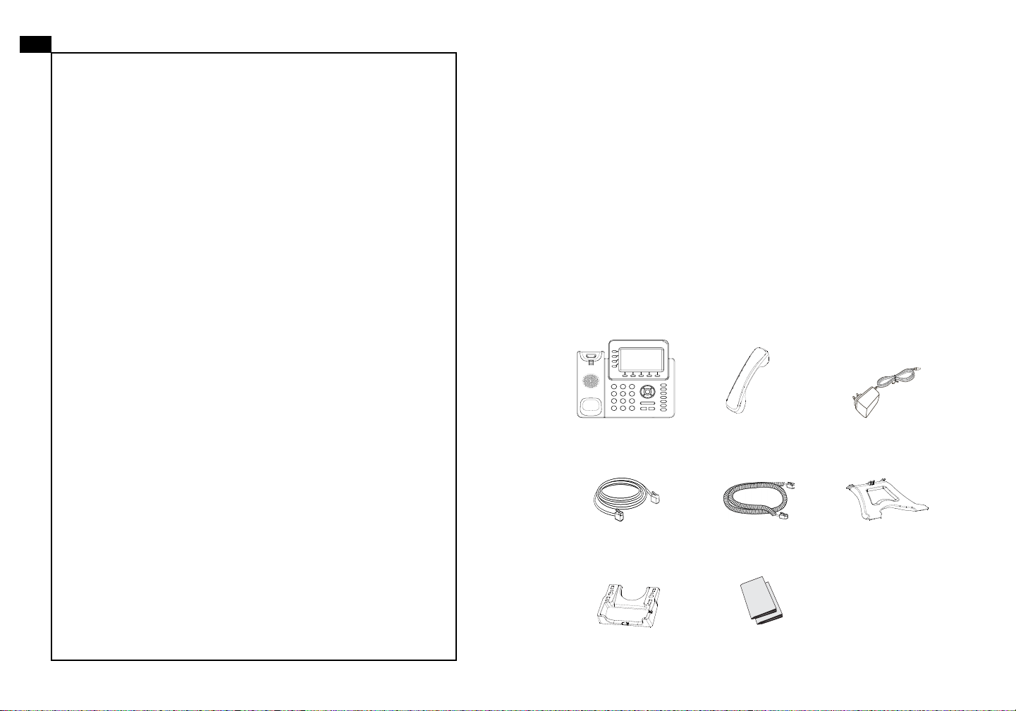
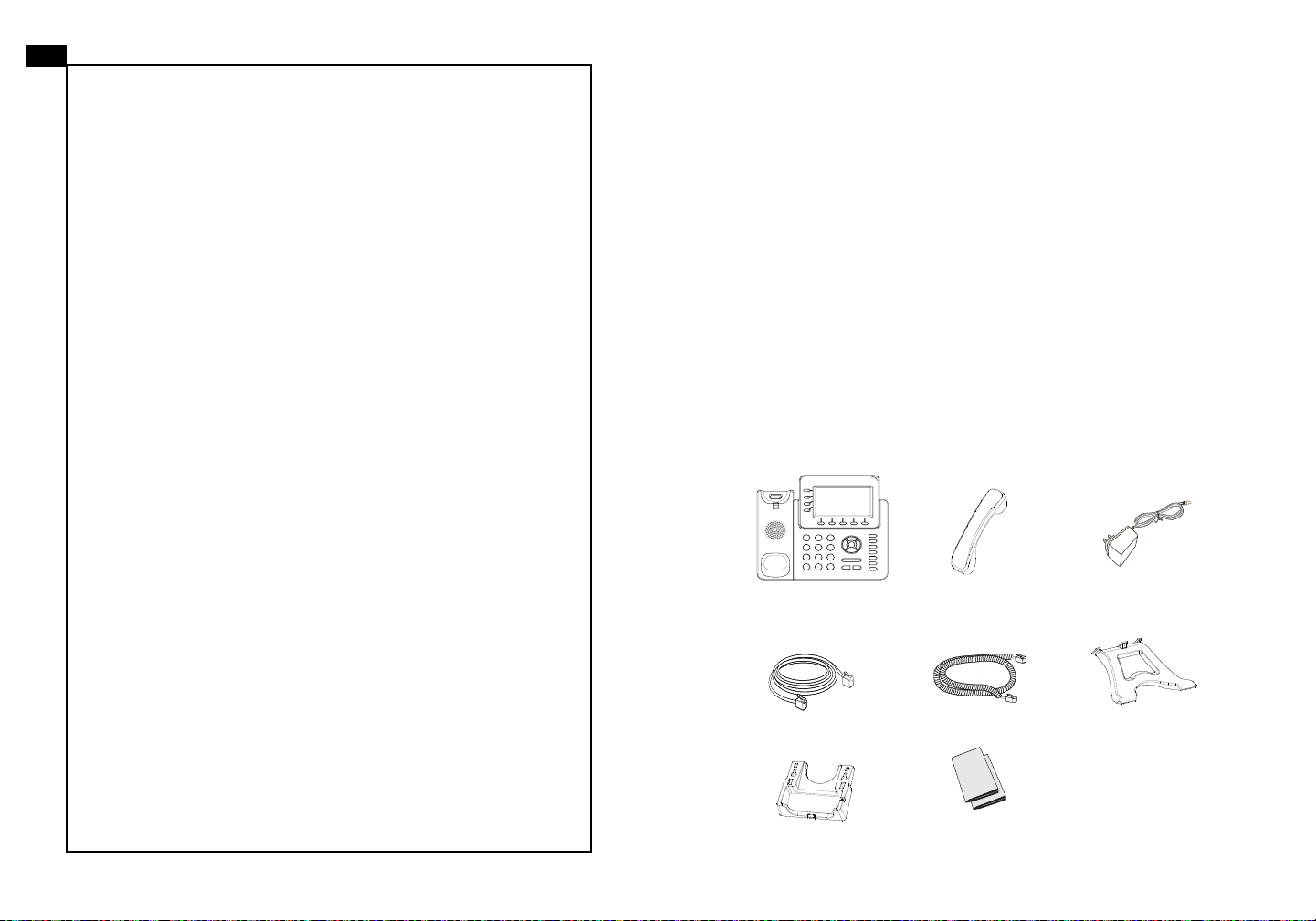
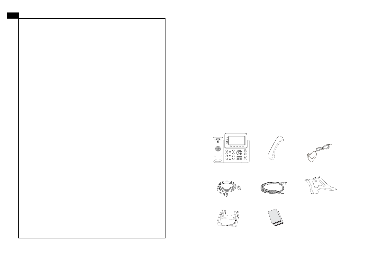
PACKAGE CONTENTS:
1 x Phone Main Case 1 x Handset
Please DO NOT power cycle the GXP2140 during system boot
Use only the power adapter included in the GXP2140 package.
12V
1 x 12V Power adapter
1 x Phone Cord1 x Ethernet Cable 1 x High Stand
1 x Wall Mount
1 x Quick Installation Guide/
1 x GPL license
1 2
Page 4
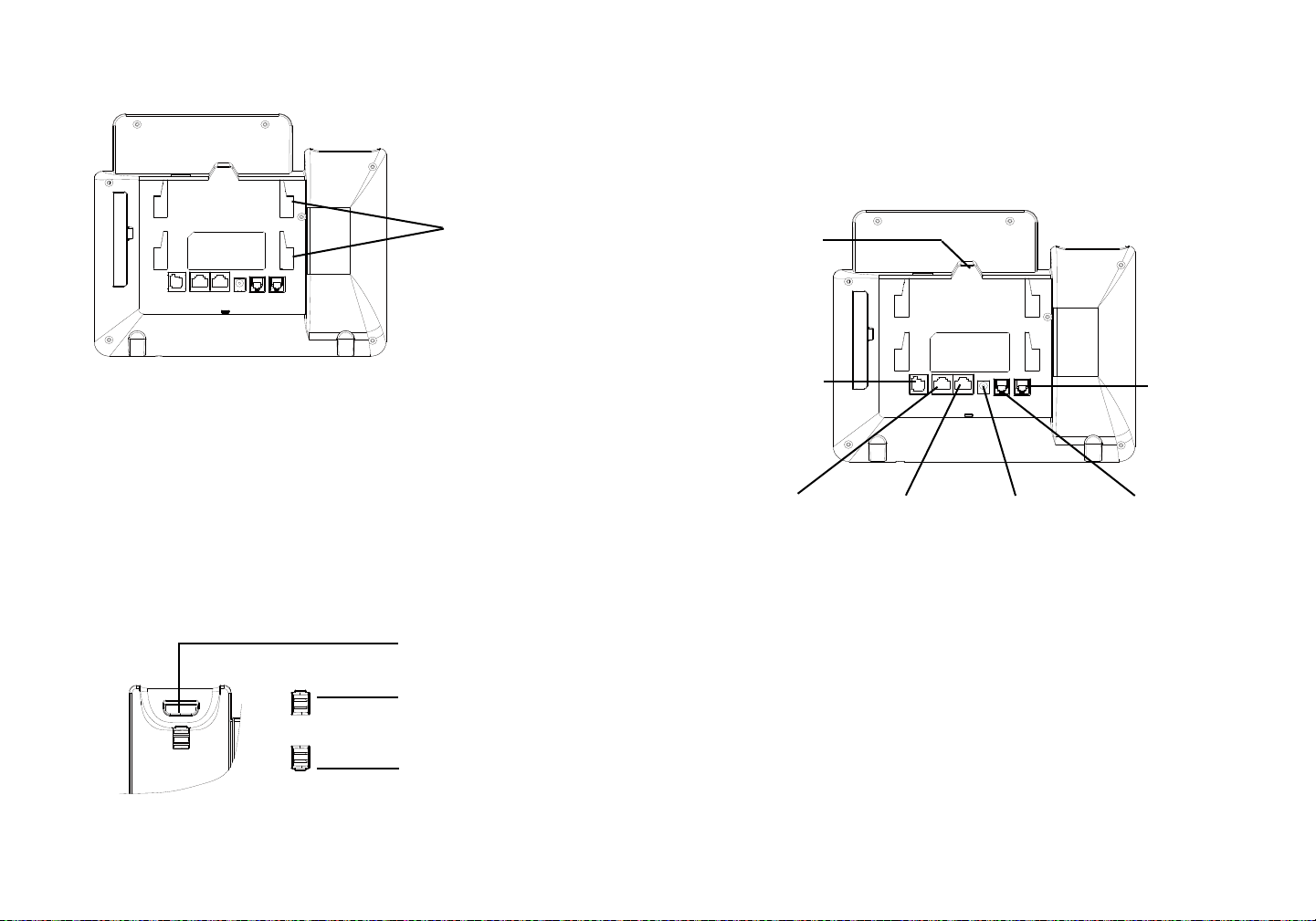
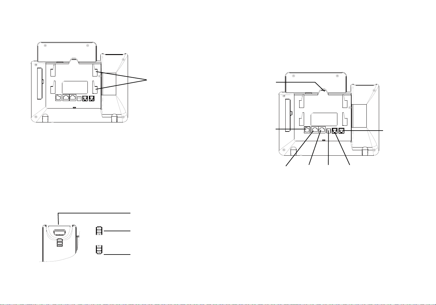
PHONE SETUP:
Installing the phone (Phone Stand) :
For installing the phone on the table with the phone stand, attach the phone stand
to the bottom of the phone where there is a slot for the phone stand. (Upper half,
bottom part).
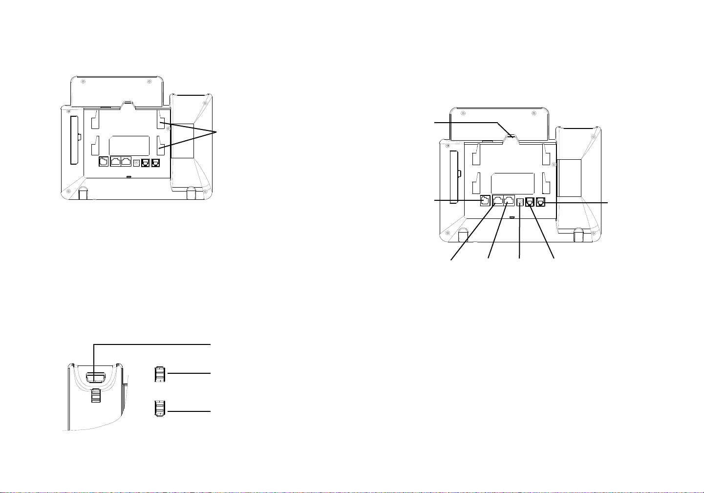
CONNECTING THE PHONE:
Slot for the wall
mount spacers and
phone stand
Installing the phone (Wall Mount):
1. Attach the wall mount spacers to the slot for wall mount spacers on the back
of the phone.
2. Attach the phone to the wall via the wall mount hole.
3. Pull out the tab from the handset cradle (See gure below).
4. Rotate the tab and plug it back into the slot with the extension up to hold the
handset while the phone is mounted on the wall (See gure below).
Handset Rest
Tab with extension up
Tab with extension down
USB Port
Extension
Module Port
PC Port
To setup the GXP2140, follow the steps below:
1. Connect the handset and main phone case with the phone cord.
2. Connect the LAN port of the phone to the RJ-45 socket of a hub/switch or a
router (LAN side of the router) using the Ethernet cable.
3. Connect the 12V DC output plug to the power jack on the phone; plug the power
adapter into an electrical outlet.
4. The LCD will display provisioning or rmware upgrade information. Before continuing, please wait for the date/time display to show up.
5. Using the phone embedded web server or keypad conguration menu, you can
further congure the phone using either a static IP or DHCP.
LAN Port Power
Headset Port
Handset Port
3
4
Page 5
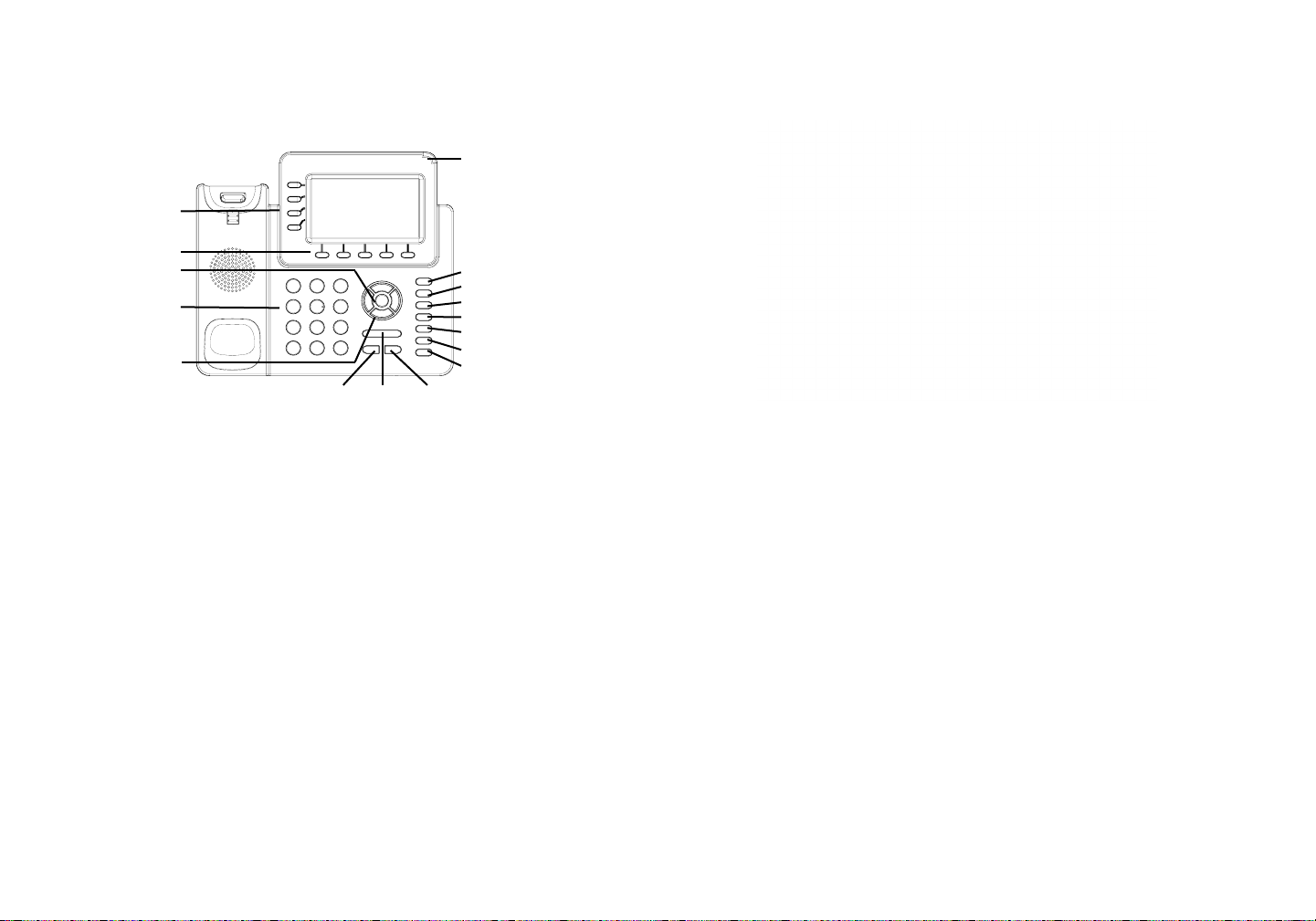
Tips For Using the Keypad:
Line keys
Message Waiting
Indicator
Soft keys
Menu/OK key
Standard keypad
Navigation keys
Send Volume Speaker
1. To access the MENU, press the round MENU button.
2. Navigate the menu by using the UP/DOWN and LEFT/RIGHT buttons.
3. Press the round MENU button to conrm a menu selection.
4. The phone automatically exits MENU mode when there is an incoming call, the
phone goes off-hook or when the MENU mode is left idle for 60 seconds.
Message
Contacts
Transfer
Conference
Hold
Handset
Mute
PHONE CONFIGURATION:
Congure the GXP2140 using a Web Browser:
1. Ensure your phone is powered up and connected to the Internet.
2. Press the UP button to see the IP address.
3. Type the phone’s IP address in your PC browser. (See Figure in next page)
4. The default administrator username and password are “admin”; the default enduser username is “user“ and the password is “123”.
Congure the GXP2140 using the Keypad:
1. Make sure the phone is idle.
2. Press the MENU button to access the keypad MENU to congure the phone.
3. Select MENU-> Phone-> SIP-> Account to congure settings for SIP Proxy,
Outbound Proxy, SIP User ID, SIP Auth ID and SIP Password.
4. Follow MENU options to congure the basic features of the phone. For
example: the IP address if using a static IP. For details, please check GXP2140
User Manual.
5. Please contact your ITSP for additional settings that may be necessary to congure the phone.
65
Page 6

GXP2140 EXTENSION MODULE:
The GXP2140 extension module is an ideal solution for the busy enterprise environment looking to add the ability to receive and dispatch calls efciently. Each extension module has 20 programmable buttons, Left and Right buttons, supporting
40 Multiple Purpose Keys to be congured. GXP2140 supports up to 4 extension
modules, adding 160 fully programmable phone extensions to the phone.
Note: The extension module is an additional accessory for the GXP2140 and is
not included in the GXP2140 box.
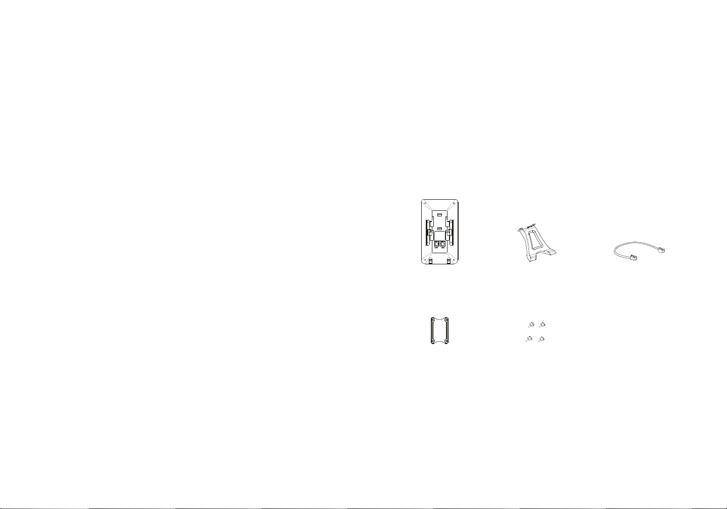
GXP2140 Extension Module Package Content:
Installing GXP2140 Extension Module:
1. On the back of GXP2140 and the extension board, there are slots for the
connector plate. Attach the connector plate between the slots for GXP2140 and
the extension board;
2. Apply the screws provided and securely tighten them in (see Figure in this
page);
1 X GXP2140
Extension Board
1 X Extension Board
Connector Plate
1 X GXP2140
Extension Board Stand
4 X Screws
1 X RJ11-RJ11 Cable
3. Connect the extension board to GXP2140 via the EXT port using the RJ11RJ11 cable provided;
4. Install the phone stand on GXP2140 and extension board;
5. Power up the GXP2140. The GXP2140 extension board will show the booting
up screen with version information and connecting status;
6. After successfully booting up, the extension board will stay in idle. Press and
hold the Left button for 3 seconds to check the version information and status.
7 8
Page 7

Conguring GXP2140 Extension Module:
ZH
1. Log into the GXP2140’s web GUI and congure Multiple Purpose Keys for
Extension board 1/2/3/4 following the GXP2140 web GUI tabs;
2. On the GXP2140 extension board, press Left or Right button to browse all the
MPKs’ status in different pages;
3. For more information, please refer to the GXP2140 user manual.
GXP2140不预设对医院,执法机构,医疗中
心(急救服务)以及各种紧急服务的紧急通话服
务。用户必须自行设定紧急通话功能。用户必
须自行购买SIP兼容的网络电话服务,正确地
设定GXP2140使用该服务,并定期测试您的
配置以确保GXP2140如预期工作,否则请购
买传统无线或有线电话服务来拨打紧急通话。
Grandstream Networks 公司的 GXP2140不支
持紧急通话服务。Grandstream Networks 公
司、其管理者和员工以及其相关机构对此所造
成的任何索赔、损失或者损害都不负有任何法
律追究责任。在此,您将无权对任何以及所有
由于无法通过GXP2140拨打紧急电话以及没
有遵照前段文字描述而造成紧急通话失败的事
件提出诉讼。
Note: For the detailed user manual, please download from:
http://www.grandstream.com/support
This product is covered by one or more of the U.S. patents (and any foreign patent
counterparts thereto) identied at www.cmspatents.com.
9 10
Page 8
注意事项:
警告:请不要在设备启动未完成或设备升级软件时断开电源,因为如刚才所述的
操作会导致话机本身的程序损坏,进而导致设备无法启动。
警告:请使用设备包装中的电源,因为使用其他没有经过认证的替代电源适配器
有可能对设备造成损害。
产品概览:
GXP2140是一款新一代企业级IP电话。GXP2140具有4个SIP账号,4条线路通
讯,4.3英寸LCD显示屏,5个可编辑XML应用程序软按键。GXP2140有2个
10/100/1000Mbps自适应交换式以太网接口(支持PoE供电),支持蓝牙功能
和EHS功能,以及最多五方会议,具有优异的高清晰语音质量和丰富完备的电话
功能。它支持自动化的个人多媒体信息服务、自动配置、先进的安全隐私保护设
置。它广泛兼容其它第三方SIP设备及主要SIP/NGN/IMS平台。对于追求品质的企
业用户来说, GXP2140将是理想的选择。
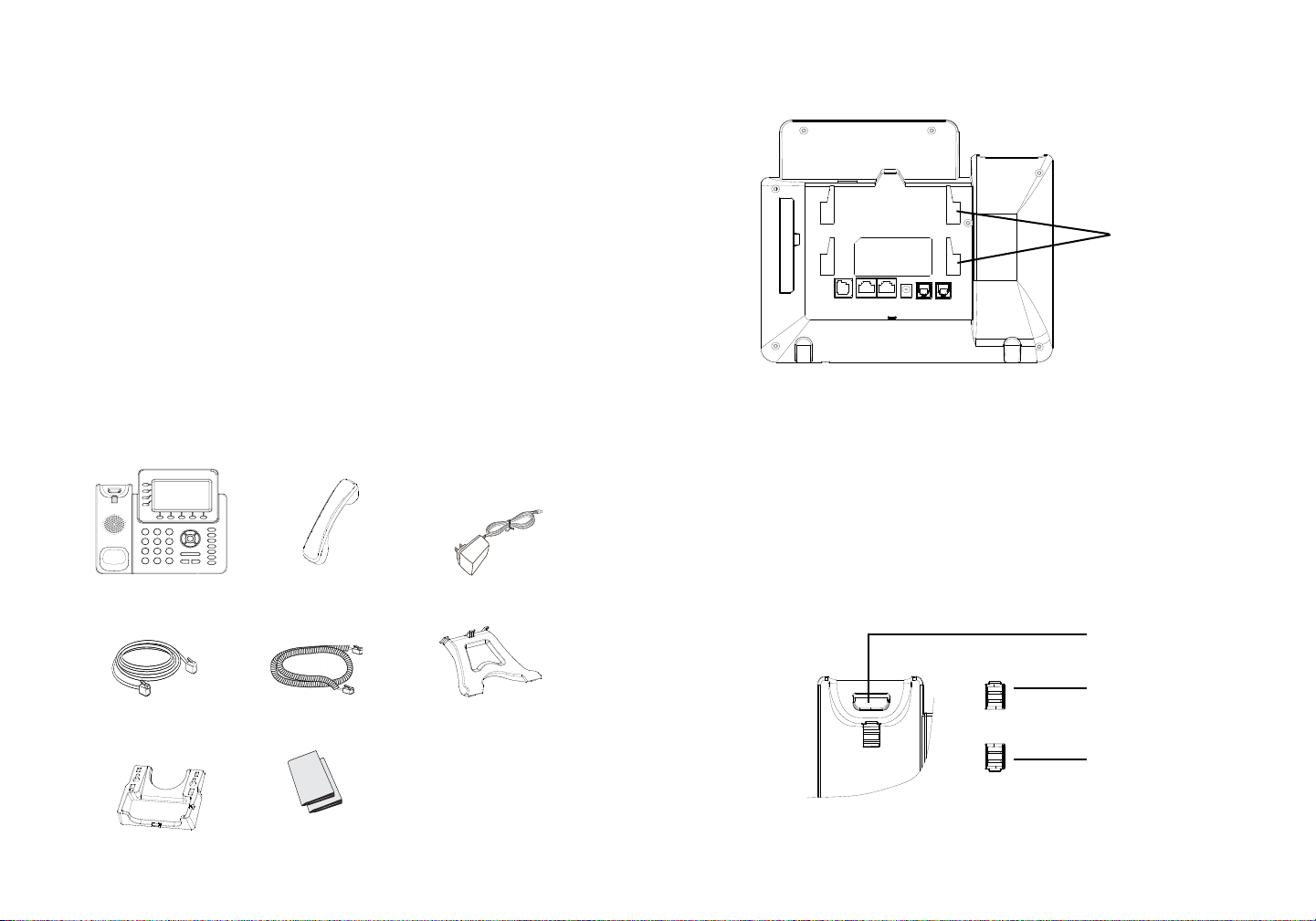
安装电话:
墙体支架槽与桌面
支架槽
设备包装清单:
12V
GXP2140话机(1台) 电话手柄(1个) 电源适配器 (1个)
网线 (1根) 手柄连线(1根) 桌面支架 (1个)
墙体支架配件(1个)
快速安装手册(1本)/
GPL许可证(1本)
11
安装电话 (墙体支架):
1. 将墙体支架插入电话背面的支架插槽中;
2. 通过墙孔将电话固定在墙上;
3. 如下图所示,将话机手柄槽下方的扣机零件取出;
4. 将该零件倒转,然后重新插入原处。此时零件凸出处在外,当电话使用墙体支
架固定在墙上时,手柄可以垂直地稳定扣入手柄槽中,不会滑落。
话机手柄插槽
凸出处向上
凸出处向下
12
Page 9

安装电话 (桌面支架):
将桌面支架插入电话背面的支架插槽中。用户可以使用两排插槽中的一排,不同
的插槽用于不同的倾斜角度。
电话的连接:
使用GXP2140键盘:
信息指示灯
线路键
USB端口
扩展板端口
PC连接端口
连线步骤:
1. 用手柄连线连接电话手柄和电话主机;
2. 用网线连接电话的网络接口和外部网络接口(如:集线器或交换机上的RJ-45网
络接口);
3. 用电源适配器连接电话电源接口和交流电源插座;
4. 电话屏幕将会显示设备启动或固件升级信息。请耐心等待至时间/日期显示;
5. 话机启动后,用户可以在主菜单或WEB浏览器进一步设置静态IP或者DHCP,
从而获得网络连接。
网络连接端口
12V电源 耳机
手柄
软按键
菜单/确认键
标准键盘
导航键
音量
发送
1. 当电话处于空闲状态,按下菜单/确定按键进入菜单选项;
2. 使用方向选择按键 “上”“下”“左”“右”选择菜单选项;
3. 按下菜单/确定按键确定选项;
4.当有来电进入,提起电话手柄、使用免提键或者电话处于菜单状态中60秒之
后,电话将自动退出菜单选项。
信息
电话薄
转接
会议
保持
手柄
静音
话筒
电话的配置:
通过WEB浏览器配置GXP2140:
1. 请确保电话的电源及网络连接;
2. 按下“上”方向键此时电话屏幕显示话机IP地址;
3. 在您电脑浏览器中输入话机IP地址(电话和您的电脑必须在同一个网段);
4.如右图所示,请输入密码登陆。默认管理员用户名和密码是“admin”;默认终
端用户名是“user”,密码是“123”。
13
14
Page 10
通过键盘配置GXP2140:
1. 确保电话处于空闲状态;
2. 按下菜单/确定按键进入菜单选项;.
3. 选择菜单->话机->SIP->账号,输入SIP服务器、SIP用户名、密码等账号信息,
注册新的SIP账号;
GXP2140扩展板:
GXP2140扩展板为企业提供了有效处理大量频繁通话的解决方案。它支持20个可
编程按键、左键和右键,可配置40个多功能键。GXP2140支持最多4个扩展板,
总共160个多功能键可以配置和使用。
注意:GXP2140扩展板是额外的配件,它使用单独的包装,因此不包含在
GXP2140包装盒中。
GXP2140扩展板包装清单:
GXP2140
扩展板(1个)
GXP2140扩展板
桌面支架(1个)
RJ11-RJ11连接线
(1根)
4. 在菜单选项中进行电话其他设置,如设置电话的静态IP地址。请参考GXP2140
产品用户手册获得更多详细配置信息;
5. 如有其他需要的设置,请联系您的服务提供商。
15
连接板(1个) 螺丝(4个)
16
Page 11

安装GXP2140扩展板:
配置GXP2140扩展板:
1.在GXP2140话机和GXP2140扩展板背面,用户可以看到用于连接板的插槽。将
连接板放置于在话机和扩展板的插槽上;
2.将包装中的螺丝安装在连接板上,从而固定GXP2140话机和GXP2140扩展板的
连接(请参见下图);
3.使用包装中的RJ11-RJ11连接线,一端接入GXP2140背面的EXT接口,一端接
入GXP2140扩展板背面接口;
4.连接GXP2140桌面支架;连接GXP2140扩展板桌面支架;
5.连接好后,启动GXP2140话机。GXP2140扩展板将显示启动界面,版本信息和
连接状态;
6.启动成功后,GXP2140扩展板将处于空闲状态。用户可以持续按住左键3秒,
查看版本信息和连接状态。
1.登陆GXP2140的WEB界面,选择相应扩展板1、2、3、4的标签,配置该扩展
板的多功能键;
2.在GXP2140扩展板上,按下左键或右键,可以浏览不同页面的多功能键状态;
3.欲获取更多详细信息,请参考GXP2140用户手册。
17
备注:欲获取详细的话机使用信息,请在以下链接中下载用户手册:
http://www.grandstream.com/support
18
Page 12

ES
El GXP2140 no esta pre-congurado para soportar
o realizar llamadas de emergencia a ningún tipo de
hospital, agencia policial, unidad de cuidado medico
o cualquier otro servicio de emergencia. Es su
responsabilidad contratar un servicio de telefonía de
Internet compatible con el protocolo SIP, congurar el
GXP2140 para utilizar dicho servicio y periódicamente
probar esta conguración para conrmar que este
trabajando como usted espera. Si es requisito no
es completado, es su responsabilidad contratar un
servicio de telefonía ja o celular para tener acceso a
servicios de emergencia.
GRANDSTREAM NO PROVEE CONEXIONES
A SERVICIOS DE EMERGENCIA A TRAVÉS
DEL GXP2120/GXP2110. NI GRANDSTREAM NI
NINGUNO DE SUS OFICIALES, EMPLEADOS O
AFILIADOS SON RESPONSABLES DE NINGUNA
DEMANDA, DAÑO O PERDIDA QUE ESTO PUEDA
OCASIONAR Y MEDIANTE ESTE COMUNICADO
USTED RENUNCIA A CUALQUIER RECLAMO O
CONSECUENCIA PROVENIENTE O RELACIONADO
DE LA INHABILIDAD DE CONTACTAR SERVICIOS
DE EMERGENCIAS CON EL GXP2140 Y SU FALTA
DE NO HABER HECHO LOS ARREGLOS DE
LUGAR PARA ACCESAR ESTOS SERVICIOS DE
EMERGENCIA DE ACUERDO CON EL PÁRRAFO ANTERIOR.
19
PRECAUCIONES:
ADVERTENCIA:
encuentren en estado intermitente al momento de iniciar el equipo o actualizar
el rmware. Esto podría ocasionar que la unidad no continúe funcionando
correctamente.
ADVERTENCIA: Solamente utilice la fuente de poder incluida en el paquete
del GXP2140. Utilizar un adaptador de poder alternativo no certicado podría
dañar su unidad.
INFORMACIÓN GENERAL:
El GXP2140 es la proxima generación de teléfono empresarial IP que cuenta
con un máximo de 4 líneas,pantalla TFT LCD a color 4.3 pulgadas, 5 teclas
suaves programables por XML, puertos de red Gigabit duales, PoE y Bluetooth
integrado, conferencia de 5 vías y descuelgue electrónico (EHS). El GXP2140
ofrece una calidad de audio superior de alta denición,con funcionalidades de
telefonía avanzada, protección de privacidad, y una amplia interoperabilidad con
la mayoría de los dispositivos SIP de terceras partes y plataformas lideres SIP/
NGN/IMS. El GXP2140 es la elección perfecta para los usuarios empresariales
que buscan una alta calidad , es un teléfono IP ejecutivo milti-lineas con todas las
funciones y prestaciones avanzadas.
CONTENIDO DEL PAQUETE:
1 X Base Principal
1 X Cable Ethernet
1 X Montura de Pared
No apague el GXP2140 cuando las luces indicadoras se
12V
1 X Auricular
1 X Cable Telefónico
1 x Guia de Instalación
Rapida / 1 x La licencia GPL
1 X Adaptador de
Alimentación 12V
1 X Soporte de Teléfono
20
Page 13

INSTALACIÓN DEL TELEFONO:
Instalando El Teléfono (Montura de Pared):
Para instalar el teléfono sobre un escritorio, utilice el soporte del teléfono y
colóquelo en la parte inferior del teléfono donde se encuentra la ranura para el
soporte.
CONECTANDO EL TELÉFONO:
Ranuras para soporte
y montura de pared
Puerto USB
Instalando el Teléfono (Montura de Pared)
1. Inserte la montura de pared en la ranura de atrás del teléfono
2. Coloque el teléfono en la pared utilizando los oricios.
3. Halé la lengüeta de la horquilla del auricular. (Ver gura abajo)
4. Coloque la lengüeta en la misma ranura de tal manera que soporte el auricular
Soporte de Auricular
Lengüeta con extensión
hacia arriba
Lengüeta con extensión
hacia abajo
21
Modulo de
Extensión
Puerto PC
Para congurar el GXP2140, siga los pasos detallados abajo:
1. Conecte el auricular a la unidad utilizando el cable telefónico.
2. Conecte el puerto LAN del teléfono al zócalo RJ-45 de un hub/switch o router
usando el cable Ethernet.
3. Conecte la fuente de poder de 12V DC a la salida de alimentación del teléfono
y la salida de electricidad.
4. La pantalla LCD va a mostrar un mensaje de aprovisionamiento o actualización
de rmware. Antes de continuar esperar hasta que la pantalla muestra el tiempo
y la fecha
5. Utilizando la interfase Web integrada accediendo la dirección IP del teléfono
en un navegador Web o mediante el teclado, congure el teléfono utilizando una
dirección IP estática o dinámica con DHCP.
Puerto LAN
Alimentación
Puerto de Receptor
de Cabeza
Puerto
Auricular
22
Page 14

Consejos para Utilizar el Teclado:
Indicador de Mensaje
en Espera
Teclas de Linea
Teclas Suaves
Programables
Tecla de Menu / OK
Teclado Estándar
Teclas de Navegación
Enviar Volumen Altavoz
1. Para accesar al MENU, presione la tecla circular MENU.
2. Para navegar el menú utilice las teclas direccionales.
3. Presione el botón de MENU para conrmar su selección.
4. El teléfono va a salir del MENU cuando hay una llamada entrante, el auricular
es levantado o cuando el teléfono permanece en reposo por 60 segundos.
Mensaje
Contactos
Transferencia
Conferencia
Retener
Receptor de Cabeza
Silenciar
CONFIGURACIÓN DEL TELÉFONO:
Congurando el GXP2140 utilizando un navegador web:
Congurando el GXP2140 usando el teclado:
1. Asegure que el teléfono se encuentre en reposo.
2. Presione la botón de MENU para acceder a el menu de teclado para congurar
el teléfono.
3. Seleccione MENU-> Teléfono-> SIP-> Cuenta para congurar el SIP Proxy,
Outbound Proxy, SIP User ID,SIP Auth ID, SIP Password.
4. Siga las opciones de MENU para congurar las funciones básicas del teléfono
por ejemplo: La Dirección IP, en caso de usar una dirección IP estática. Para
obtener más información, consulte el Manual del usuario de la GXP2140.
5. Por favor contacte a su PSI (Proveedor de Servicio de Internet) para los ajustes
adicionales que sean necesarios para congurar el teléfono.
MODULO DE EXTENSIÓN GXP2140:
1. Asegure que su teléfono este conectado a la red y tenga electricidad.
2. Presione el botón de ARRIBA para ver la dirección IP.
3. Escriba la dirección IP en su navegador web (Ver la gura en la página
siguiente)
4. El nombre de usuario y contraseña de administrador predeterminado es
“admin”; el nombre de usuario para usuario nal es “user” y la contraseña “123”.
El modulo de extensión GXP2140 EXT es una solución ideal para empresas
de alto traco que quieren mejorar la eciencia de la recepción y el despacho
de llamadas. Cada modulo de expansión tiene 20 teclas programables del lado
izquierdo y la misma cantidad del lado derecho, soportando 40 teclas programables
.El teléfono GXP2140 soporta hasta cuatro módulos EXT, añadiendo hasta 160
teclas programables al teléfono.
Nota: El modulo de extensión es un accesorio adicional para el GXP2140 y no
está incluido en el paquete.
2423
Page 15

Contenido del Paquete Modulo de Extensión GXP2140:
1. Em la parte de atras del GXP2140 y el modulo de extensión, están las ranuras
para la placa de conexion. Colocar la placa entre las ranuras del GXP2140 y el
modulo de extensión;
2. Colocar los tornillos y aprietar rmemente;
3. Conecte el modulo de extensión a el GXP2140 a través del puerto EXT
utilizando el cable RJ11-RJ11 suministrado;
4. Instala la base del teléfono on el GXP2140 y el modulo de extensión;
1 X Modulo de Extensión
GXP2140
1 X Placa de conexión de
Modulo de Extensión
1 X Soporte de Modulo de
Extensión GXP2140
4 X Tornillos
Intalando el Modulo de Extensión GXP2140:
1 X Cable RJ11-RJ11
5. Encienda el GXP2140. El modulo de extensión GXP2140 mostrará la pantalla
de arranque con información de la versión y el estado de conexión;
6. Después de arrancar con éxito, el modulo de extensión se quedará en espera.
Pulse y mantenga pulsado el botón izquierdo durante 3 segundos para comprobar
la información de versión y estado.
Congurando el Modulo de Extensión GXP2140:
1. Inicie sesión en la interfaz Web del GXP2140 y congure las teclas
programables de los modulos de extensión1/2/3/4 siguiendo las pestañas de la
pagina web del GXP2140;
2. En el modulo de extensión GXP2140, pulselas teclas izquierda o derecha para
navegar por todos los estados de las teclas programables.
3. Para mayor información, por favor reerase a el manual de usuario del
GXP2140.
25
Nota: Para obtener el manual de usuario, favor haga click aquí:
http://www.grandstream.com/support
26
Page 16
FR
Le GXP2140 n’est pas préconguré pour prendre en
charge ou acheminer les appels d’urgence adressés
aux hôpitaux, organismes chargés de l’application
de la loi, centres de soins médicaux (« service(s)
d’urgence ») ou tout autre type de service d’urgence.
Vous devez prendre des dispositions supplémentaires
pour assurer l’accès aux services d’urgence. Il est de
votre responsabilité de vous abonner à un service
de téléphonie Internet conforme au protocole SIP, de
congurer correctement le GXP2140 pour utiliser ce
service, et de tester périodiquement votre conguration
pour vous assurer qu’elle fonctionne comme prévu. Si
vous ne le faites pas, vous devez vous abonner à un
service de téléphonie sans l ou xe traditionnel pour
accéder aux services d’urgence.
GRANDSTREAM NE FOURNIT PAS DE CONNEXIONS
AUX SERVICES D’URGENCE VIA LE GXP2140. NI
GRANDSTREAM, NI SES DIRIGEANTS, EMPLOYES
OU SOCIETES AFFILIEES NE PEUVENT ETRE TENUS
RESPONSABLES POUR TOUTE RECLAMATION, TOUT
DOMMAGE OU PERTE, ET VOUS RENONCEZ PAR
LES PRESENTES A TOUTE RECLAMATION OU TOUT
MOTIF D’ACTION EN JUSTICE DÉCOULANT OU LIE A
VOTRE INCAPACITE D’UTILISER LE GXP2140 POUR
CONTACTER LES SERVICES D’URGENCE, ET TOUTE
NEGLIGENCE DE VOTRE PART QUANT A PRENDRE DES
DISPOSITIONS SUPPLEMENTAIRES POUR ACCEDER
AUX SERVICES D’URGENCE CONFORMÉMENT À
L’ALINÉA PRÉCDENT.
27
PRECAUTIONS:
ALERTE:
système ou la mise à jour du rmware. Ceci peut corrompre l’image du rmware
et causer un dysfonctionnement de l’unité.
Veuillez ne pas redémarrer le GXP2140 lors du démarrage du
ALERTE: N’utilisez que l’adaptateur d’alimentation fourni dans le pack
GXP2140. L’utilisation d’un autre adaptateur d’alimentation non qualié peut
endommager l’unité.
PRESENTATION:
GXP2140 représente la nouvelle génération des téléphones IP conçus pour les
grandes entreprises, offrant jusqu’à 4 lignes, écran TFT couleurs LCD de 4.3
inch, 5 touches XML contextuelles programmables, deux ports réseau Gigabit,
PoE et Bluetooth intégrés, conférence à 5 participants, et crochet commutateur
électronique (EHS). Le GXP2140 offre une qualité de son HD supérieure, riche
en fonctionnalités à la pointe de la téléphonie, la protection de la vie privée avec
sécurité avancée, et une large interopérabilité avec la majorité des produits
SIP tiers, et des plateformes SIP/NGN/IMS leaders. Le GXP2140 est le choix
parfait pour les entreprises à la recherche d’un téléphone IP multi-lignes riche
en fonctionnalités et de haute qualité avec des performances et fonctionnalités
supérieures.
CONTENU DU PACK:
12V
1 x Appareil GXP2140 1 x Combiné
1 x Câble Ethernet
1 x Fixation Murale
1 x Câble téléphonique
1 x Guide d’installation
rapide / 1 x License GPL
1 x Adaptateur
d’alimentation 12V
1 x Support du téléphone
28
Page 17

INSTALLATION DU TELEPHONE:
Fentes pour la xation
murale et support du
téléphone
Installation du téléphone (Support du téléphone):
Pour installer le téléphone sur la table avec le support du téléphone, attachez
ce dernier à la fente placée à la base du téléphone (partie Supérieure, partie
Inférieure).
CONNECTER LE TÉLÉPHONE:
Reportez-vous à l’illustration ci-dessous en suivant les instructions d’installation.
Port USB
Installation du téléphone (Fixation murale):
1. Attachez le support de xation murale à la fente située à l’arrière du téléphone.
2. Attachez le téléphone au mur via la fente de xation murale.
3. Tirez la languette du support du combiné (Voir gure ci-dessous).
4. Pivotez la languette et rebranchez-la dans la fente en gardant son appui vers
le haut pour tenir le combiné lorsque le téléphone est xé au mur (Voir gure cidessous).
Appui du Combiné
Languette avec appui
vers le haut
Languette avec appui
vers le bas
29
Port
Module
d’extension
Port PC
Pour installer le GXP2140, suivez les instructions ci-dessous:
1. Connectez le combiné et le boîtier du téléphone principal avec le câble
téléphonique.
2. Connectez le port LAN de votre téléphone au port RJ-45 d’un concentrateur/
commutateur ou un routeur (côté LAN du routeur) à l’aide du câble Ethernet.
3. Connectez la che de sortie 12V DC à la prise d’alimentation sur le téléphone;
branchez l’adaptateur dans une prise électrique.
4. Le LCD va afcher les informations d’approvisionnement ou de mise à jour du
rmware. Avant de continuer, veuillez patienter jusqu’à que la date/heure s’afche.
5. En utilisant le serveur web intégré du téléphone ou le menu de la conguration
du téléphone, vous pouvez le congurer en utilisant soit IP statique ou DHCP.
Port LAN Alimentation
Port Casque
Port
Combiné
30
Page 18

Conseils d’utilisation du clavier :
Touches Lignes
Indicateur de
message en attente
Touches contextuels
Touche Menu/OK
Clavier standard
Touches de
naviguation
Envoyer
1. Pour accéder au MENU, appuyez sur le bouton circulaire MENU.
2. Naviguez dans le menu en utilisant les boutons HAUT/BAS et GAUCHE/
DROITE.
3. Appuyez sur le bouton circulaire MENU pour conrmer la sélection.
4. Le téléphone quitte automatiquement le MENU quand il y a un appel entrant,
si le téléphone est décroché, ou lorsque le MENU est inactif pendant 60
secondes.
Volume
Messsage
Contacts
Transfert
Conférence
Mise en attente
Casque
Muet
Haut-parleur
CONFIGURATION DU TELEPHONE:
Congurer le GXP2140 en utilisant le Navigateur web:
1. Vériez que votre téléphone est sous tension et connecté à Internet;
2. Appuyez sur le bouton HAUT pour afcher l’adresse IP;
3. Saisissez l’adresse IP du téléphone dans votre navigateur PC (voir gure à la
page suivante);
4. Le mot de passe d’administrateur par défaut est “admin”, le mot de passe
“utilisateur” par défaut est “123”.
Congurer le GXP2140 en utilisant le Clavier:
1. Assurez-vous que le téléphone est libre.
2. Appuyez sur le bouton “MENU” pour accéder au MENU pour congurer le
téléphone.
3. Sélectionnez MENU -> Phone -> SIP -> Account, pour congurer les paramètres
du Proxy SIP, Proxy Sortant, Nom d’utilisateur SIP, Nom d’authentication SIP,
mot de passe SIP.
4. Suivez les options du MENU pour congurer les fonctionnalités de base du
téléphone. Par exemple: l’adresse IP si vous utilisez une adresse IP statique.
Pour plus de détails, veuillez vérier le manuel d’utilisation du GXP2140.
5. Veuillez contacter votre Fournisseur d’accès Internet pour les paramètres
supplémentaires qui peuvent être nécessaires pour congurer le téléphone.
LE MODULE D’EXTENSION DU
GXP2140:
Le module d’extension du GXP2140 est une solution idéale pour les entreprises
à environnement chargé à la recherche de la possibilité de recevoir et répartir
les appels avec efcience. Chaque module d’extension possède 20 touches
programmables, touches de gauche et droite, supportant ainsi 40 Touches
Multi-fonctions à congurer. Le GXP2140 peut supporter jusqu’à 4 modules
d’extensions, ajoutant ainsi 160 touches d’extension totalement programmables
au téléphone.
Remarque: Le module d’extension est un accessoire supplémentaire pour le
GXP2140 et il n’est pas inclus dans la boite du GXP2140.
31
32
Page 19

Contenu du paquet du module d’extension GXP2140:
1 X Module d’extension
du GXP2140
1 X Plaque de connecteur
Module d’extension
1 X Support du module
d’extension du GXP2140
4 X Vis
1 X Câble RJ11-RJ11
1. A l’arrière du GXP2140 et du module d’extensions se trouve des fentes des
connecteurs de la plaque. Attachez la plaque des connecteurs entre les fentes du
GXP2140 et la carte d’extension;
2. Mettez les vis fournies et vissez-les correctement;
3. Connectez le module d’extension au GXP2140 via le port EXT en utilisant le
câble RJ11-RJ11 fourni;
4. Installez le support du téléphone du GXP2140 ainsi que le module d’extensions;
5. Alimentez le GXP2140. Le module d’extensions du GXP2140 afchera l’écran
de démarrage avec les informations de la version et le statut de connexion;
6. Le module d’extensions restera en veille. Appuyez et maintenez la touche
Gauche appuyée pendant 3 secondes pour vérier les informations de version
et statut.
CONFIGURATION DU MODULE D’EXTENSION DU GXP2140:
Installation du module d’extension du GXP2140:
33
1. Accédez à l’interface web du GXP2140 et congurer les Touches MultFonctions pour les modules d’extensions 1/2/3/4 suivant les onglets de l’interface
web du GXP2140;
2. Sur la carte d’extension du GXP2140, appuyez sur le bouton Gauche ou Droite
pour visualiser les états de toutes les Touches Multi-Fonctions sur différentes
pages;
3. Pour plus d’informations, veuillez consulter le manuel d’utilisation du GXP2140.
Note : Pour le manuel d’utilisation détaillé, veuillez le télécharger a partir de :
http://www.grandstream.com/support
34
Page 20
DE
Im GXP2140 sind keine Notfallrufnummern voreingestellt
oder vorkonguriert. Das GXP2140 tätigt keine
automatischen Anrufe zu medizinischen, sozialen oder
juristischen Hilfs- oder Serviceorganisationen. Die
Anbindung an derartige Einrichtungen muss separat
eingestellt bzw. zur Verfügung gestellt werden. Es liegt
in der Verantwortung des Nutzers, einen SIP-konformen
Internet-Telefon-Service zu buchen, der die Nutzung der
örtlichen und überregionalen Notrufnummern sicherstellt.
Bietet der SIP-Anbieter diesen Service nicht, liegt es in
der Verantwortung des Nutzers, einen analogen bzw.
alternativen Telefonanschluss zusätzlich bereitzustellen,
um eine telefonische Anbindung für Notfälle sicherstellen
zu können.
GRANDSTREAM STELLT MIT DEM GXP2140 KEINE
VERBINDUNG ZU NOTFALLRUFNUMMER ODER DIE
ANBINDUNG AN NOTFALLZENTREN ZUR VERFÜGUNG.
WEDER GRANDSTREAM, NOCH GRANDSTREAM
MITARBEITER, ANGESTELLTE ODER SONSTIGE
FIRMEANGEHÖRIGE SIND FÜR DIE ANDBINDUNG
DES GXP2140 AN EINEN MEDIZINISCHEN SERVICE
ODER ANDEREN NOTFALLDIENST ZUSTÄNDIG,
BZW. VERANTWORTLICH.ES OBLIGT ALLEINIG IN
DER VERANTWORTUNG DER GXP2140 NUTZER
BZW. DER GXP2140 BESITZER, FÜR EINE
NETZANBINDUNG ZU SORGEN, WELCHE DIE
NUTZUNG VON MEDIZINISCHEN ODER ANDEREN
NOTFALLRUFNUMMERN SICHERSTELLT.
SICHERHEITSHINWEISE:
ACHTUNG: Bitte unterbrechen Sie während des Systemstarts bzw.
während eines Software-Upgrades des GXP2140 NICHT die Stromzufuhr. Eine
Unterbrechung kann ein Fehlverhalten hervorrufen und das Telefon zerstören.
ACHTUNG: Benutzen Sie nur das Netzteil, das im Lieferumfang enthalten
ist. Die Verwendung eines anderen Netzteils kann zu Schäden bzw. zum Defekt
führen.
ÜBBERBLICK:
Das GXP2140 ist ein “Next Generation“ IP Telefon für die professionelle
Kommunikation in kleinem, mittleren und großen Unternehmen. Es bietet bis zu 4
SIP Konten, 4,3“ TFT Farb-Display, 5 XML frei-programmierbare Softtasten, DualGigabit Netzwerkanschluss, Integriertes PoE und Bluetooth, 5-er Konferenz sowie
Elektronik Hook Switch (EHS) zur Annahme von ankommenden Gesprächen am
Headset. Das GXP2140 bietet seinen Anwendern bestmögliche Sprachqualität,
eine Vielzahl an allgemeinen und individuellen Telefonfunktionen, Einstellungen
zum Schutz der persönlichen Daten, sowie eine hohe Kompatibilität zu den
meisten SIP/NGN/IMS Plattformen von Service-Providern und Drittanbietern
(3rd Party). Das GXP2140 ist die richtige Wahl für alle Anwender, die ein
hochqualitatives, umfangreich ausgestattetes IP Telefon suchen, und dabei nicht
auf schönes Design verzichten möchten.
LIEFERUMFANG:
12V
1 x Telefonapparat 1 x Hör-Sprecheinheit
1 x Netzwerkkabel
(Ethernet)
1 x Telefon- Spiralkabel
1 x 12V Netzteil
1 x Standfuß für das
Telefon
35
1 x Aufsatz zur
Wandmontage
1 x Kurz- Installationsanleitung / 1 x GPL Lizenz
36
Page 21
EINRICHTEN DES TELEFONS:
Eingebauter Steckplatz für
die Wandhalterung und
den Standfuß
Installation des Telefons (Tischmontage):
Zur Nutzung des Telefons am Tisch, führen Sie bitte den mitgelieferten Standfuß
in die auf der Rückseite des Telefons vorgesehene Montagesteckplätze ein.
ANSCHLUSSMÖGLICHKEITEN AM TELEFON:
USB
Anschluss
Installation des Telefons (Wandmontage):
1. Führen Sie die Wandhalterung auf der Rückseite des Telefons in die dafür
vorgesehenen Steckplätze ein.
2. Zur Montage des Telefons an der Wand nutzen Sie bitte die dafür vorgesehenen
Montagelöcher.
3. Ziehen Sie das Sicherungsplättchen aus der Hörerauage heraus ( Siehe
untere Skizze).
4. Drehen Sie das Sicherungsplättchen und und stecken Sie es wieder in den
Steckplatz. Das Plättchen sollte nun weiter als zuvor herausstehen, sodass
die Hör-Sprecheinheit für die Wandmontage besser xiert werden kann. (Siehe
untere Skizze).
Auage für die Hör-
Sprecheinheit
Position für das
Sicherungsplättchen bei
Wandmontage
Position für das
Sicherungsplättchen bei
Wandmontage
37
Anschluss für
das Tastenerwe-
iterungsmodul
PC-Anschluss Netzwerkanschluss
Das Telefon schrittweise zusammenbauen:
1. Verbinden Sie die Hör-Sprecheinheit mit dem Telefon, indem Sie das Spiralkabel
in die dafür vorgesehenen Steckplätze stecken.
2. Verbinden Sie den Netzwerk-Anschluss (RJ45) am Telefon, mit dem dafür
vorgesehenen Router / Switch, nutzen Sie hierfür das Netzwerkkabel mit dem
RJ45 Stecker.
3. Verbinden Sie das Netzteil mit dem Telefon und stecken dieses dann in die
Steckdose.
4. Am Display werden Informationen über den Provisionierungsvorgang sowie
zur Software-Version angezeigt. Warten Sie bitte mit weiteren Aktionen, bis am
Display das aktuelle Datum, sowie die aktuelle Uhrzeit erscheint.
5. Sie können jetzt die weiteren Telefoneinstellungen vornehmen, indem Sie das
Telefon via integrierten Web-Server oder über die Telefontasten kongurieren.
Stromanschluss
Headset-Anschluss
Anschluss
für die Hör-
Sprecheinheit
38
Page 22

Tipps zur Konguration über das Tastenfeld:
Nachrichtenanzeige
Leitungstasten
Softtasten
Menü /
Bestätigungstaste
(OK Taste)
Standard Tasten
Navigationstasten
Lautstärke
Senden
1. Um in das Einstellungsmenü zu gelangen, drücken Sie bitte die MENÜ-Taste.
2. Navigieren Sie durch das Menü mit den Tasten AUF/AB und LINKS/RECHTS.
3. Drücken Sie die runde Menütaste, um eine Auswahl zu bestätigen.
4. Das Telefon verlässt den Menü-Modus automatisch bei einem eingehenden
Anruf, wenn der Hörer abgenommen oder wenn länger als 60 Sekunden keine
Taste gedrückt wird.
Nachricht
Kontakte
Verbinden
Konferenz
Halten
Hör-Sprecheinheit
Stumm
Lautsprecher
KONFIGURATION DES TELEFONS ÜBER DAS TASTENFELD:
1. Stellen Sie sicher, dass das Telefon im Bereitschaftsmodus ist.
2. Drücken Sie die MENÜ Taste, um in das Kongurationsmenü des Telefons zu
gelangen.
3. Wählen Sie MENÜ > Telefon > SIP > Konto um die Einstellungen für SIP
Proxy, Outbound Proxy, SIP-Nutzer ID, SIP Authentizierungs-ID, sowie das SIP
Passwort zu kongurieren.
4. Über die MENÜ Optionen können Sie die Basisfunktionen des Telefons
kongurieren, wie z.B. die Einstellung der IP Adresse, wenn eine statische
(feste) IP Adresse genutzt wird. Weitere Kongurationsdetails nden Sie im
Benutzerhandbuch des GXP2140.
5. Bitte kontaktieren Sie Ihren Internet-Service-Provider um alle zur Konguration
notwendigen Einstellungen zu erfahren.
KONFIGURATION DES TELEFONS:
GXP2140 TASTENERWEITERUNGSMODUL
Konguration des GXP2140 via Web-Browser:
1. Stellen Sie sicher, dass das Telefon eingeschaltet ist und eine Internetverbindung
besteht.
2.Drücken Sie die UP Taste um die IP Adresse zu sehen.
3. Geben Sie die IP Adresse des Telefons in die Adresszeile Ihres Webbrowsers
ein. (Siehe Skizze auf der nächsten Seite)
4. Der voreingestellte Administrator-Benutzername sowie das voreingestellte
Passwort ist jeweils „admin“, der voreingestellte Nutzer-Benutzername ist „user“,
das Passwort ist „123“.
Das GXP2140 Erweiterungsmodul ist die ideale Ergänzung für schnelles und
efzientes Arbeiten. Jedes Erweiterungsmodul besitzt 20 freiprogrammierbare
Tasten, die durch eine Umblätter-Möglichkeit 40 Funktionen je Tastenfeld
bereitstellen. Das GXP2140 unterstützt bis zu 4 Erweiterungsmodule und bietet
somit 160 programmierbare Funktionstasten.
Bitte beachten Sie: Die Erweiterungsmodule sind optional erhältlich und nicht im
Lieferumfang des GXP2140 enthalten.
39 40
Page 23

Lieferumfang GXP2140 Tastenerweiterungsmodul:
1. Auf der Rückseite des Telefons sowie des Erweiterungsmoduls benden sich
Montagesteckplätze - in diesen wird die Montageplatte xiert.
2. Drehen Sie nun die Schrauben in die dafür vorgesehenen Löcher am Telefon
sowie am Erweiterungsmodul.
3. Verbinden Sie das Telefon mit dem Erweiterungsmodul indem Sie das RJ11
– RJ11 Kabel in den EXT Anschluss am Telefon sowie den Anschluss am
Erweiterungsmodul stecken.
1 X GXP2140
Tastenerweiterungsmodul
1 X Verbindungsplatte zur Montage des
Erweiterungsmoduls an das elefon
1 X GXP2140 Standfuß
für das Erweiterungsmodul
1 X RJ11 – RJ11 Kabel
4 X Schrauben
Installation des GXP2140 Erweiterungsmoduls:
4. Installieren Sie den Standfuß am Erweiterungsfeld.
5. Stecken Sie nun das Netzteil des Telefons in die Steckdose, um das Telefon
sowie das Erweiterungsmodul zu starten. Am Display erhalten Sie Informationen
zur Software Version sowie zum Verbindungsstatus.
6. Nach erfolgtem Start bleibt das Erweiterungsmodul im Bereitschaftsmodus.
Drücken Sie die linke Taste länger als drei Sekunden um Statusinformationen zu
erhalten.
KONFIGURATION DES GXP2140 TASTENERWEITERUNGSFELD:
1. Melden Sie sich an der Web-Schnittstelle des GXP2140 an und kongurieren
Sie die jeweiligen Tasten für die Erweiterungsmodule 1/2/3/4 über das WEBKongurationsmenü.
2. Drücken Sie die Links / Rechts Tasten am Erweiterungsmodul um die
unterschiedlichen Belegungen der einzelnen Tasten zu sehen.
3. Weitere Informationen entnehmen Sie bitte dem Benutzerhandbuch des
GXP2140.
41
Bitte beachten Sie: Das erweiterte Benutzerhandbuch erhalten Sie unter:
http://www.grandstream.com/support
42
Page 24

IT
GXP2140 non è precongurato per supportare o
effettuare chiamate di emergenza a qualsiasi tipo di
ospedale, struttura giudiziaria, unità di assistenza
medica (“Servizi di emergenza”) o a qualsiasi altro
tipo di servizio di emergenza. È necessario effettuare
accordi supplementari per accedere ai Servizi di
emergenza. E’ a Vostra esclusiva responsabilità
acquistare servizi di telefonia internet conformi
con SIP, congurare GXP2140 correttamente per
usare tale servizio ed effettuare test periodici della
congurazione per assicurarsi che funzioni in modo
idoneo. Se non si effettua ciò, è Vostra responsabilità
acquistare servizi telefonici ssi o wireless tradizionali
per accedere ai Servizi di emergenza.
GRANDSTREAM NON FORNISCE COLLEGAMENTI
AI SERVIZI DI EMERGENZA ATTRAVERSO GXP2140.
NÈ GRANSTREAM NÈ I SUOI RESPONSABILI,
DIPENDENTI O AFFILIATI POSSONO ESSERE
RITENUTI RESPONSABILI DI QUALSIASI
RECLAMO, DANNO O PERDITA, E DI QUALSIASI
AZIONE LEGALE DERIVANTE DA TALI RECLAMI
O CAUSE IN RELAZIONE ALL’IMPOSSIBILITÀ DI
USARE IL GXP2140 PER CHIAMATE AI SERVIZI
O DI STRINGERE ACCORDI SUPPLEMENTARI
PER ACCEDERE AI SERVIZI DI EMERGENZA IN
CONFORMITÀ AL PARAGRAFO PRECEDENTE.
PRECAUZIONI:
ATTENZIONE:
del sistema o l’aggiornamento del rmware. Ciò potrebbe comportare il
danneggiamento del rmware e il malfunzionamento dell’unità.
ATTENZIONE: Usare solo l’alimentatore incluso nella confezione del
GXP2140. L’uso di un alimentatore alternativo non idoneo potrebbe danneggiare
l’unità.
PANORAMICA:
GXP2140 è un telefono IP di nuova generazione caratterizzato da 4 linee, LCD
a colori TFT da 4,3’’, 5 tasti funzione XML sensibili al contesto programmabili,
porte di rete Gigabit doppie, PoE e Bluetooth integrato, conferenza a 5 vie e
interruttore a sgancio elettronico (EHS). Il GXP2140 garantisce una qualità di
audio HD superiore, ricche e all’avanguardia funzioni di telefonia, protezione della
privacy e ampia interoperabilità con la maggior parte di dispositivi SIP di terzi e
piattaforme leader SIP/NGN/IMS. GXP2140 è la scelta perfetta per utenti impresa
che cercano un telefono IP esecutivo, multilinea, ricco di funzionalità e di alta
qualità con funzioni e prestazioni avanzate.
CONTENUTO DELLA CONFEZIONE:
1 x Case unità principale telefono
NON spegnere/accendere il GXP2140 durante l’avvio
12V
1 x Ricevitore
1 x Cavo telefonico1 x Cavo ethernet 1 x Supporto telefono
1 x Alimentatore 12V
43
1 x Supporto
montaggio a parete
1 x Guida rapida di installazione / 1 x GPL licenza
44
Page 25

MONTAGGIO TELEFONO:
Slot per montaggio
a parete e supporto
telefono
Installazione del telefono (supporto telefono):
Per installare il telefono sul tavolo con il supporto telefono, ssare il supporto
alla base del telefono dove si trova un alloggiamento per tale supporto. (metà
superiore, parte inferiore).
CONNESSIONE DEL TELEFONO:
Fare riferimento all’illustrazione riportata di seguito quando si seguono le istruzioni di installazione.
Porta USB
Installazione del telefono (montaggio a parete):
1. Fissare i distanziali per il supporto a parete nell’apposito alloggiamento sul retro
del telefono
2. Fissare il telefono alla parete attraverso il foro di montaggio a parete.
3. Estrarre l’aletta dal ricevitore (si veda la gura di seguito).
4. Ruotare l’aletta e riposizionarla nell’alloggiamento con l’estensione verso l’alto
in modo da poter sostenere il telefono mentre è montato a parete (si veda la gura
di seguito).
Supporto del ricevitore
Aletta con estensione
verso l’alto
Aletta con estensione
verso il basso
45
Porta modulo
estensione
Porta PC Porta LAN Alimentazione Porta cufa
Per impostare il GXP2140, seguire la seguente procedura:
1. Collegare il ricevitore e il case principale del telefono con il cavo telefonico.
2. Collegare la porta LAN del telefono alla presa RJ-45 di un hub o di un router
(lato LAN del router) usando un cavo ethernet.
3. Collegare il jack dell’alimentatore all’uscita 12V CC sul telefono; collegare
l’alimentatore a una presa elettrica.
4. L’LCD visualizzerà le informazioni relative allo stato dell’apparecchio o
all’aggiornamento del rmware. Prima di continuare, attendere che il display
visualizzi data/ora.
5. Usando il server web del telefono o il menu di congurazione del tastierino
numerico, è possibile inoltre congurare il telefono usando o un IP statico o un
DHCP.
Porta
ricevitore
46
Page 26

Consigli per l’uso del tastierino:
Tasti linea
Indicatore
Messaggio in
attesa
Tasti funzione
Tasto Menu/OK
Tastierino standard
Tasti per la navigazione
Invia
Volume
1. Per accedere al MENU, premere il pulsante circolare MENU.
2. Muoversi nel menu usando i pulsanti UP/DOWN e LEFT/RIGHT.
3. Premere il pulsante circolare MENU, per confermare una scelta effettuata nel
menu.
4. Il telefono esce automaticamente dalla modalità MENU quando arriva una
chiamata, quando il telefono è sganciato o quando la modalità MENU non è usata
per 60 sec.
Messaggio
Contatti
Trasferimento
Conferenza
Tenere in linea
Cufa
Silenzia
Altoparlante
CONFIGURAZIONE DEL TELEFONO:
Congurazione del GXP2140 mediante un browser web:
1. Assicurarsi che il telefono sia in corrente e collegato a internet.
2. Premere il tasto UP per vedere l’indirizzo IP.
3. Digitare l’indirizzo IP del telefono nel browser del vostro PC. (Si veda la gura
alla pagina successiva).
4. Il nome utente e la password amministratore predenita sono “admin”; il nome
utente per l’utente nale predenito è “utente” e la password è “123”.
Congurazione del GXP2140 mediante il tastierino:
1. Assicurarsi che il telefono sia in stato di attesa (modalità idle).
2. Premere il pulsante MENU per accedere al tastierino MENU per congurare il
telefono.
3. Selezionare MENU-> Phone-> SIP-> Account, per congurare le impostazioni
Proxy SIP, Proxy in uscita, ID utente SIP, ID Aut SIP e Password SIP.
4. Seguire le opzioni del MENU per congurare le impostazioni di base del
telefono. Alcuni esempi: l’indirizzo IP se si usa un IP statico. Per ulteriori
informazioni, consultare il manuale utente di GXP2140.
5. Contattare il vostro ITSP (fornitore servizi di telefonia internet) per
le impostazioni supplementari che possono essere necessarie per la
congurazione del telefono.
MODULO DI ESTENSIONE GXP2140:
Il modulo di estensione GXP2140 è una soluzione ideale per l’impresa che mira
ad ottenere una perfetta possibilità di ricevere ed effettuare chiamate. Ciascun
modulo di estensione ha 20 pulsanti programmabili, pulsanti Sinistra e Destra,
40 tasti multi-funzione da poter congurare. GXP2140 supporta no a 4 moduli
di estensione, aggiungendo 160 estensioni completamente programmabili al
telefono.
47
Nota: Il modulo di estensione è un accessorio aggiuntivo per il GXP2140 e non è
incluso nella confezione del GXP2140.
48
Page 27

Contenuto confezione modulo di estensione GXP2140:
1 X Modulo di
estensione GXP2140
1 X Supporto modulo
di estensione GXP2140
1 X Cavo RJ11-RJ11
1. Sul retro del GXP2140 e del modulo di estensione, ci sono slot per la piastra del
connettore. Fissare la piastra del connettore tra gli slot per GXP2140 e il modulo
di estensione;
2. Applicare le viti fornite e serrarle (si veda la gura in questa pagina);
3. Collegare il modulo di estensione al GXP2140 mediante la porta EXT usando
il cavo RJ11-RJ11 fornito;
4. Installare il supporto del telefono sul GXP2140 e il modulo di estensione;
5. Accendere il GXP2140. Il modulo di estensione GXP2140 mostrerà la schermata
di avvio con le informazioni relative alla versione e lo stato della connessione;
6. Dopo l’avvio, il modulo di estensione resterà in stand-by. Premere e tenere
premuto il pulsante Sinistra per 3 secondi per vericare le informazioni sulla
versione e lo stato.
1 X Modulo di estensione
Piastra connettore
4 X Viti
Installazione del modulo di estensione GXP2140:
49
CONFIGURAZIONE DEL MODULO DI ESTENSIONE GXP2140:
1. Accedere al GUI web di GXP2140 e congurare i tasti multifunzione per il
modulo di estensione 1/2/3/4 seguendo le schede del GUI web GXP2140;
2. Sul modulo di estensione GXP2140, premere il pulsante Sinistra o Destra per
scorrere tutti gli stati di MPK nelle diverse pagine;
3. Per informazioni più dettagliate, fare riferimento al manuale utente di GXP2140.
Nota: Scaricare il manuale utente dettagliato da:
http://www.grandstream.com/support
50
Page 28

RU
GXP2140 предварительно не сконфигурирован для
поддержки или переноса экстренных звонков в какиелибо больницы, правоохранительные органы, отделения
медицинской помощи (“Экстренная (-ые) Служба (-ы)”), или
какие-либо другие Экстренные службы. Следует произвести
дополнительные настройки для доступа к Экстренным
Службам. Вы ответственны за подключение SIP-совместимой
интернет-телефонной службы, правильную настройку
GXP2140 для ее использования, а также периодическое
тестирование Вашей конфигурации для проверки ее
работы в соответствии с Вашими требованиями. Если Вы
это не сделаете, Вы будете ответственны за подключение
традиционных беспроводных или проводных телефонных
служб для доступа к Экстренным Службам.
GRANDSTREAM НЕ ПРЕДОСТАВЛЯЕТ СОЕДИНЕНИЯ С
ЭКСТРЕННЫМИ СЛУЖБАМИ ПОСРЕДСТВОМ GXP2140.
GRANDSTREAM, ЕГО СЛУЖАЩИЕ, РАБОТНИКИ И
ОТДЕЛЕНИЯ НЕ НЕСУТ ОТВЕТСТВЕННОСТИ ЗА
ПРЕТЕНЗИИ, УЩЕРБ ИЛИ УТРАТУ, И ВЫ НАСТОЯЩИМ
ОТКАЗЫВАЕТЕСЬ ОТ КАКИХ-ЛИБО ЗАЯВЛЕНИЙ ИЛИ
ИСКОВЫХ ОСНОВАНИЙ, ПРОИСТЕКАЮЩИХ ИЗ ВАШЕЙ
НЕСПОСОБНОСТИ ИСПОЛЬЗОВАТЬ GXP2140 ДЛЯ
СВЯЗИ С ЭКСТРЕННЫМИ СЛУЖБАМИ И НЕПРИНЯТИЯ
С ВАШЕЙ СТОРОНЫ МЕР ПО ОБЕСПЕЧЕНИЮ ДОСТУПА
К ЭКСТРЕННЫМ СЛУЖБАМ В СООТВЕТСТВИИ С
ВЫШЕСЛЕДУЮЩИМ ПАРАГРАФОМ.
МЕРЫ ПРЕДОСТОРОЖНОСТИ:
ВНИМАНИЕ: Пожалуйста, НЕ ПЕРЕЗАГРУЖАЙТЕ GXP2140 ПУТЕМ
ВЫКЛЮЧЕНИЯ ПИТАНИЯ во время начальной загрузки системы или
обновления встроенной программы. Вы можете повредить образы
встроенной программы и вызвать неправильную работу устройства.
ВНИМАНИЕ: Используйте только блок питания, входящий в комплект
поставки GXP2140. Использование неподходящего блока питания может
вызвать повреждение устройства.
ОБЗОР:
GXP2140 представляет собой промышленный IP-телефон нового поколения,
поддерживающий до 4-х линий, и оснащенный цветным TFT LCD экраном,
пятью XML-программируемыми контекстно-зависимыми клавишами,
двумя сетевыми портами Gigabit, встроенным PoE и Bluetooth, поддержкой
режима конференции до 5 участников, и электронным переключателем
рычага (EHS). GXP2140 обеспечивает превосходное HD-качество аудио,
большой набор передовых функций телефонии, защиту приватности,
и широкую совместимость с большинством SIP-устройств и ведущих
платформ SIP/NGN/IMS сторонних производителей. GXP2140 - идеальный
выбор для бизнес-пользователей, которым требуется высококачественный,
многофункциональный многопотоковый IP-телефон с продвинутыми
функциями и повышенной работоспособностью.
КОМПЛЕКТ ПОСТАВКИ:
12V
1 x Телефон 1 x трубка
1 x Блок питания 12В
51
1 x Крепление на
стену
1 x Телефонный шнур1 x кабель Ethernet 1 x Подставка под
телефон
1 x Краткие руководства по
установке / 1 x GPL лицензия
52
Page 29
УСТАНОВКА ТЕЛЕФОНА:
Установка телефона (Подставка) :
Для установки телефона на стол на подставке, присоедините подставку к
днищу телефона в гнездо для подставки. (Верхняя половина, нижняя часть).
ПОДКЛЮЧЕНИЕ ТЕЛЕФОНА:
Слоты для крепления
на стену и подставка
Установка телефона (Крепление на стену):
1. Прикрепите прокладки стенного крепления к слотам стенного крепления
на задней части телефона.
2. Прикрепите телефон к стене посредством отверстия стенного крепления.
3. Вытащите контакт из гнезда трубки (См. рисунок ниже).
4. Поверните контакт и вставьте его обратно в гнездо расширением вверх,
когда телефон прикреплен к стене (См. рисунок ниже).
Трубка положена
Контакт с расширением
вверх
Контакт с расширением
вниз
53
USB-Порт
Порт модуля
расширения
Порт ПК Порт LAN
Для установки GXP2140, следуйте инструкциям:
1. Соедините трубку с телефоном с помощью телефонного шнура.
2. Подключите LAN-порт телефона к гнезду RJ-45 хаба/коммутатора или
маршрутизатора (сторона LAN роутера) с помощью кабеля Ethernet.
3. Подсоедините штекер блока питания 12В DC к гнезду телефона;
подключите блок питания к сети.
4. На LCD будет выводиться информация об инициализации или обновлении
встроенной программы. Перед продолжением, пожалуйста, дождитесь
отображения экрана дата/время.
5. Используя встроенный веб-сервер или меню конфигурации клавиатуры,
вы можете произвести дальнейшую конфигурацию телефона с помощью
статического IP или DHCP.
Сеть Порт гарнитуры
Порт
трубки
54
Page 30

ССоветы по использованию клавиатуры:
Индикатор ожидания
сообщения
Линейные клавиши
Программируемые
клавиши
Клавиша Menu/OK
Стандартная клавиатура
Навигационные клавиши
Отправить
1. Для доступа в МЕНЮ, нажмите круглую клавишу “MENU”.
2. Перемещение по меню осуществляется посредством кнопок UP/DOWN и
LEFT/RIGHT.
3. Нажмите круглую клавишу MENU для подтверждения выбора.
4. Телефон автоматически выходит из режима МЕНЮ при входящем звонке,
снятии трубки или отсутствия действий в режиме МЕНЮ в течение 60 секунд.
Громкость
Сообщение
Контакты
Передать
Конференция
Удержание
Трубка
Выключить звук
Динамик
КОНФИГУРАЦИЯ ТЕЛЕФОНА:
Сконфигурируйте GXP2140 с помощью веб-браузера:
1. Убедитесь, что Ваш телефон включен и подключен к Интернет.
2. Нажмите кнопку UP, чтобы увидеть IP-адрес.
3. Введите IP-адрес Вашего телефона в браузере на Вашем ПК. (См. рисунок
на следующей странице).
4. Имя администратора по умолчанию - “admin”; имя конечного пользователя
- “user”, пароль - “123”.
Сконфигурируйте GXP2140 с помощью клавиатуры:
1. Убедитесь, что телефон не занят.
2. Нажмите кнопку MENU для доступа к МЕНЮ клавиатуры для конфигурации
телефона.
3. Выберите MENU-> Phone-> SIP-> Account для настройки параметров
SIP-прокси, Исходящего прокси, Идентификатора пользователя SIP,
Идентификатора авторизации SIP, и пароля SIP.
4. Воспользуйтесь опциями МЕНЮ для конфигурации основных функций
телефона. Например, IP address, если Вы используете статический IP. За
подробностями обращайтесь к Пользовательской Инструкции GXP2140.
5. Пожалуйста, обратитесь к Вашему провайдеру Интернет-телефонии
за дополнительными настройками, которые могут потребоваться для
конфигурации телефона.
МОДУЛЬ РАСШИРЕНИЯ GXP2140:
Модуль расширения GXP2140 - идеальное решение для активной бизнессреды, где требуется дополнительная возможность эффективного приема
и перенаправления звонков. Каждый модуль расширения оснащен 20
программируемыми клавишами, кнопками Влево и Вправо, поддержкой 40
конфигурируемых многофункциональных клавиш. GXP2140 поддерживает
до 4-х модулей расширения, что позволяет добавить к телефону 160
полностью программируемых расширений.
Примечание: Модуль расширения является дополнительным аксессуаром
для GXP2140 и не входит в комплект поставки GXP2140.
5655
Page 31

Содержимое комплекта поставки модуля
расширения GXP2140:
1 X Панель
расширения GXP2140
1 X Розетка Панели
расширения
1 X Подставка под панель
расширения GXP2140
4 X Винты
Установка модуля расширения GXP2140:
1 X Кабель RJ11-RJ11
ПУСТАНОВКА МОДУЛЯ РАСШИРЕНИЯ GXP2140:
1. На задней части GXP2140 и модуле расширения расположены гнезда
для панели соединителя Закрепите панель соединителя между слотами для
GXP2140 и панелью расширения;
2. Установите и надежно закрепите приложенные винты (См. рисунок на
данной странице);
3. Подключите панель расширения к GXP2140 посредством порта EXT с
помощью приложенного кабеля RJ11-RJ11;
4. Установите подставку для телефона на GXP2140 и панель расширения;
5. Включите GXP2140. На панели расширения GXP2140 будет отображен
экран загрузки с информацией о версии и статусе подключения;
6. После успешной загрузки модуль расширения будет оставаться в
свободном режиме. Нажмите кнопку Влево и удерживайте ее в течение 3-х
секунд для проверки информации о версии и статуса.
КОНФИГУРАЦИЯ МОДУЛЯ РАСШИРЕНИЯ GXP2140:
1. Войдите в графический Веб-интерфейс GXP2140 и настройте
Многоцелевые Клавиши для Модуля Расширения 1/2/3/4 в соответствии с
вкладками графического Веб-интерфейса;
2. На панели расширения GXP2140, нажмите кнопки Влево и Вправо для
просмотра статуса всех MPK на различных страницах;
3. За более подробной информацией обращайтесь к пользовательской
инструкции GXP2140.
Примечание: Для более подробной пользовательской инструкции
перейдите по ссылке: http://www.grandstream.com/support
5857
 Loading...