

Graff 8075 Installation Instructions Manual
IOG 2216.01
Rev. 1 April 2010
1
Dear Customer Estimado Cliente
Thank you for selecting our product. We are confident we can fully satisfy Muchas gracias por elegir nuestro producto. Estamos seguros que podemos
your expectations by offering you a wide range of technologically advanced
satisfacer completamente sus expectativas ofreciéndole una amplia variedad
products which directly result from our many years of experience in faucet
de productos tecnológicamente avanzados que resultan directamente de
and fitting production.
muchos años de experiencia en grifos y su producción apropiada.
ENGLISH
~
ESPANOL
Installation Instructions Instrucciones de Instalación
3/4 STOP/VOLUME CONTROL VALVES
3/4 VÁLVULAS REGULADORAS DE CIERRE
For care, use soft towel with soap and water only! Under no
circumstances should you use any chemicals.
ATTENTION!
ATENCIÓN!
Para el cuidado, utilice solamente una toalla suave con jabón
y aqua! Bajo ninguna circunstancia no use productos químicos.
For easy installation of your Para la instalación fácil de su válvula de la
GRAFF valve you will need: GRAFF usted necesitará:
to READ ALL the instructions completely before beginning, LEER TODAS las instrucciones completamente antes de comenzar,
to READ ALL the warnings, care and maintenance information. LEER TODA la información sobre las advertencias, cuidado y mantenimiento.
To complete the project, you should: Para terminar el proyecto, usted debe:
gather the tools and all the parts you will need, recolectar las herramientas y todas las piezas que usted necesitará,
prepare the mounting area, prepare el área para el montaje,
mount the stop/volume control valve, monte la válvula reguladora de cierre
finally test and flush the valve. finalmente pruebe y limpie la válvula con un chorro de agua
You should have the following tools: Usted debe tener las herramientas siguientes:
1/2" and 3/4” nominal fittings manguitos nominales 1/2" y 3/4"
wrenches llaves
thin-bladed knife or screwdriver cortaplumas o destornillador plano
hacksaw or tubing cutter sierra para metal o cortador de tubos
thread sealant obturador de la rosca
~
ESPANOL
ENGLISH
Single-handle wall-mount stop/volume control valves are Las válvulas monomando de cierre/control de flujo, montadas
of brass construction. Products feature 1/2” (8070 model) and a la pared se fabrican de latón. Los productos poseen una válvula
3/4” (8075 model) quarter-turn washerless ceramic disc valve. con disco cerámico sin arandela de cuarto de vuelta, 1/2” (en el
Products also feature 1/2" N.P.T. (8070 model) and 3/4” modelo 8070) y 3/4” (en el modelo 8075).
N.P.T. (8075 model) female connections. Los productos poseen también conexiones tipo hembra 1/2"
N.P.T. (en el modelo 8070) y 3/4” N.P.T. (en el modelo 8075).
~
ESPANOL
ENGLISH
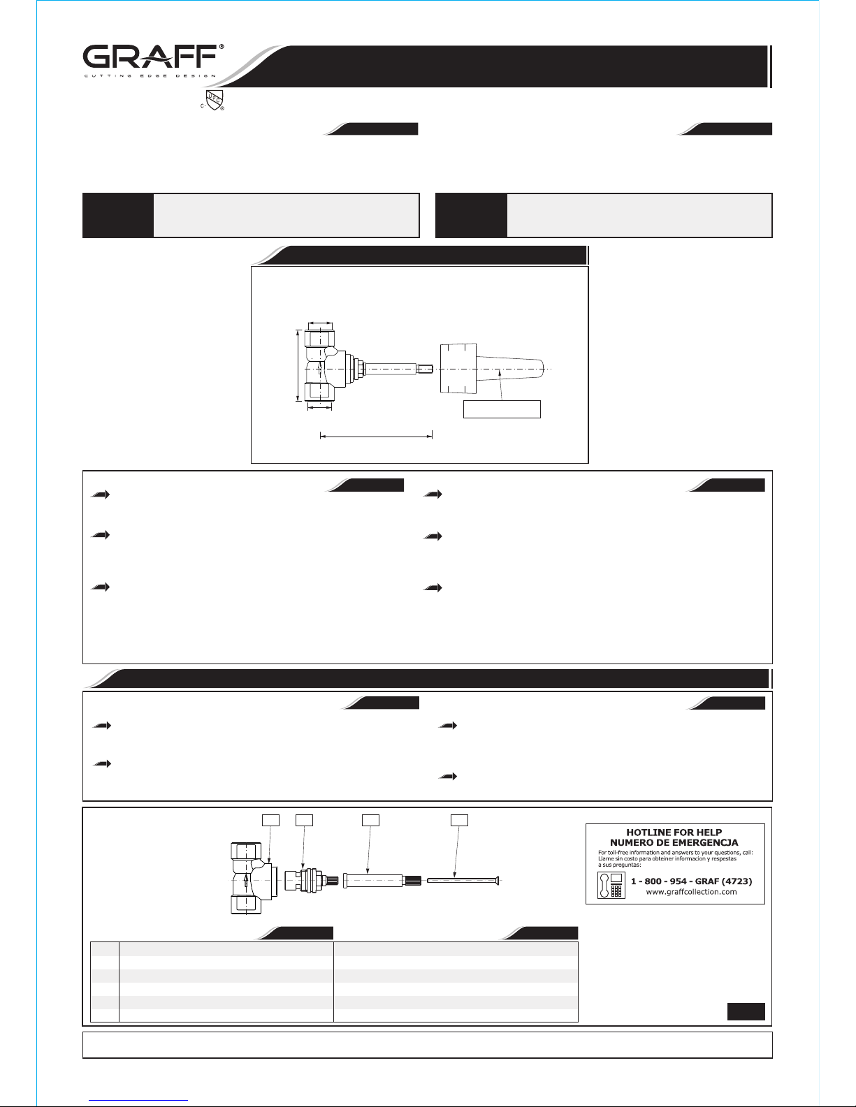
PRODUCT SPECIFICATION DESCRIPCIÓN DEL PRODUCTO
R1 R2 R3 R4
1.1
R1
R2
R3
R4
~
ESPANOL
ENGLISH
SÓLO LA VÁLVULA DESBASTADO 8070
CUERPO DE VÁLVULA 3/4" NPT
3/4" CABEZA CERÁMICA (CARTUCHO) 1/4 DE VUELTA,
hacia la izquierda
EXTENSION
TORNILLO
8070 ROUGH ONLY
STOP/VOLUME CONTROL VALVE BODY 3/4" NPT
3/4" CERAMIC HEAD (CARTRIDGE) 1/4 turn,
counterclockwise opening
ELONGATION
SCREW
All dimensions and drawings are for reference only. For details, please refer to actual products.
Todas las dimensiones y dibujos sirven únicamente de referencia. Para consultar detalles, ver los productos.
3/4" Stop Valve/Volume Control (Rough Only)
3/4" Válvula Reguladora de Cierre (Sólo la Válvula Desbastado)
3-5/16" (77mm)
PLASTER GUARD
PROTECTOR DEL YASO
3/4 NPT-14
FEMALE
3/4 NPT-14
FEMALE
5-1/32" (128mm)
WALL MIN
WALL MAX
8075
Model
Modelo
This faucet complies with NSF61/9, ASME/ANSI A112.18.1
and CSA B 125 Standards.
Este grifo se encuentra conforme con losestandares de NSF61/9,
de ASME/ANSI A112.18.1 y de CSA B 125.
IOG 2216.01
Rev. 1 April 2010
2
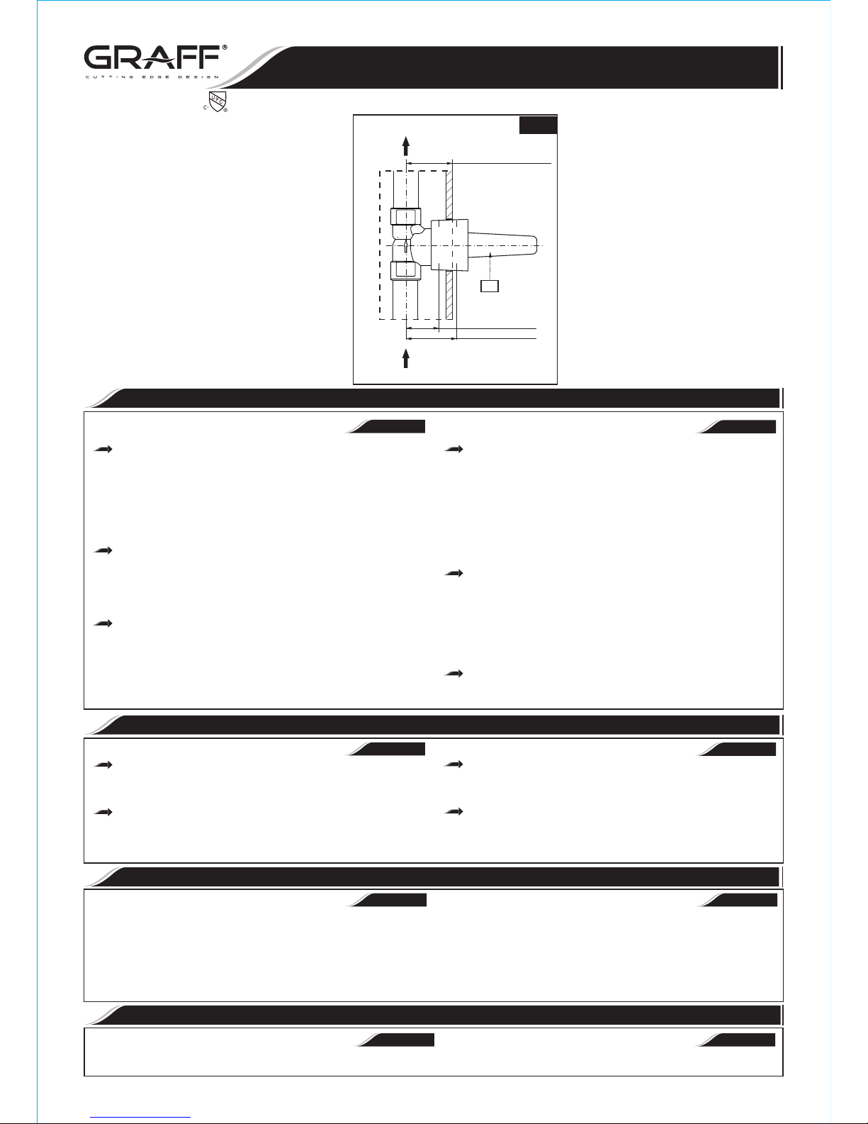
WALL MIN
WALL MAX
A
MIN.1-3/8"-MAX.2-1/8"
(MIN.35mm-MAX.54mm)
WATER SUPPLY
(from Thermostatic Mixing Valve)
SUMINISTRO DE AGUA
(del la Válvula Mezcladora Termostática)
TO RECEIVER
AL RECEPTOR
MIN. 1-3/8" (35mm)
MAX. 2-1/8" (54mm)
2.1
Prepare the recess in the wall for the valve body pipe Prepare la hendidura en la pared para el trabajo de la tuberia
work taking into account the maximum and minimum del cuerpo del mezclador considerando la profundidad máxima y
depth allowed. Place valve body with plaster guard (A) mínima permitida. Ponga el cuerpo de la válvula con protector del
into the wall recess. Recommended depth for valve body in yaso (A) en la hendidura de la pared. La profundidad recomendada
wall measured from center of valve outlet to finished wall para el cuerpo de válvula en la pared medida del centro del enchufe
surface is in the range 1-3/8” (35mm) - 2-1/8” (54mm). de la válvula a la superficie acabada de la pared esta en el intervalo
de 1-3/8” (35mm) - 2-1/8” (54mm).
Turn on the water supply lines to the valve, and check for
leaks. Run water through the mixing valve and all shower
Abrir las líneas de suministro del agua para la válvula y
devices, and check the system for leakage. Use the
controlar si no hay fugas. Dejar pasar el agua por la válvula
stop/volume control valve to control the water flow to the
mezcladora y por todos los elementos de la ducha y controlar si no
shower outlets.
hay fugas en el sistema. Usar la válvula de cierre/control de flujo
para controlar el flujo del agua por los cańos de la ducha. Cerrar el
agua. Terminar el acabado de la pared.
~
ESPANOL
ENGLISH
INSTALLATION INSTRUCTIONS INSTRUCCIONES DE INSTALACIÓN
See fig. 1.1, 2 1 Ver dis. 1.1 2 1. ,
Use correct piping use size accordingly from mixing valve to
stop volume control for optimal GPM perfomance.
Cap or plug outlets and test setup for leaks.
Turn off check valve stops on mixing valve.
Complete the finished wall. Flash all water lines.
: Remove cartridge if heating up the valve body
CAUTION
The water flow is opened using the lever or the cross handle. It is Para abrir la salida I de ajuste de temperatura sirve la palanca o la
opened fully by turning the lever (cross handle) in counterclockwise llave cruzados. Obtenemos la apertura completa girando la palanca (la
direction. llave cruzados) en la dirección opuesta al movimiento del reloj.
Lever or cross handle is used to open and regulate the flow of Para abrir la salida y ajustar el flujo del agua sirven la palanca o la
water. The flow is opened fully by rotating the lever or cross handle by llave cruzados . La apertura total la obtenemos girando la palanca o la
0
quarter-turn countercl ockwise. The intensity of the water flow is llave cruzada 90 en contra del sentido de las manillas del rejol. La
0 0
regulated by positions between 0 ÷ 90 angle. regulación de la intensidad del flujo del agua sucede en las posiciones
0 0
entre 0 y 90 .
~
ESPANOL
ENGLISH
OPERATING INSTRUCTIONS DESCRIPCIÓN DEL FUNCIONAMIENTO
ENGLISH
~
ESPANOL
CARE AND MAINTENANCE CUIDADO Y MANTENIMIENTO
Your Graff valve is designed and engineered in accordance with the Su válvula de la Graff esta diseńado y se regido de acuerdo con los
highest quality and performance standards. Be sure not to damage the estándares de funcionamiento y calidad más altos. Este seguro no dańar las
finish during installation. Care should be given to the cleaning of this terminaciones del grifo durante la instalación. Cuide el producto
product. Although its finish is extremely durable, it can be damaged by manteniendolo siempre limpio. Aunque su acabado es extremadamente
harsh abrasives or polish. Never use abrasive cleaners, acids, durable, puede ser dańado por los abrasivos o pulientes ásperos. Nunca
solvents, etc. to clean any Graff product. To clean, simply wipe utilice limpiadores abrasivos, ácidos, solventes, el etc. para limpiar
gently with a damp cloth and blot dry with a soft towel. cualquier producto de la Graff. Para limpiar, simplemente use un
pańo húmedo y seque con una toalla suave.
~
ESPANOL
ENGLISH
WARRANTY GARANTÍA
Warranty conditions and warranty registration card are outlined on a Las condiciones de la garantía y la tarjeta del registro de la garantía se
separate sheet. encuentran en una pagina separada.
Use el de
de control de volumen a fin de obtener un
rendimiento óptimo de galones por minuto GPM.
correcto respectivamente, desde la
tamańo cańeria
válvula mezcladora hasta
la
válvula
Tape o conecte las solidas
y verifique que no existan fugas.Cierre los topes de las
válvulas
de retención que se encuentran en la
válvula mezcladora.
Haga correr agua por todas las lineas de agua.
PRECAUTIÓN:
Quite el cartucho si se produce el
calentamiento del cuerpo de la
válvula .
Installation Instructions Instrucciones de Instalación
3/4 STOP/VOLUME CONTROL VALVES
3/4 VÁLVULAS REGULADORAS DE CIERRE
This faucet complies with NSF61/9, ASME/ANSI A112.18.1
and CSA B 125 Standards.
Este grifo se encuentra conforme con losestandares de NSF61/9,
de ASME/ANSI A112.18.1 y de CSA B 125.
 Loading...