

Graco Merkur A Series, Merkur LW025A, Merkur LW075A, Merkur LW100A, Merkur LW050A Repair And Parts Manual
...
Repair/Parts
Merkur
®
312792F
Displacement Pump
For use with high-performance finishing and coating pumps in hazardous and
non-hazardous locations. For professional use only.
Important Safety Instructions
Read all warnings and instructions in this manual.
For complete warnings and instructions see your
pump or package manual. Hazard symbols refer to
specific procedure risks. Save all instructions.
See page 3 for model information, including maximum working pressures.
LW025A
LW150A
ENG
TI11643a
TI11645

Related Manuals
Contents
Related Manuals . . . . . . . . . . . . . . . . . . . . . . . . . . . 2
Models . . . . . . . . . . . . . . . . . . . . . . . . . . . . . . . . . . . 3
Component Identification . . . . . . . . . . . . . . . . . . . . 4
Repair . . . . . . . . . . . . . . . . . . . . . . . . . . . . . . . . . . . . 5
General Information . . . . . . . . . . . . . . . . . . . . . . 5
Preparation . . . . . . . . . . . . . . . . . . . . . . . . . . . . . 5
Disassembly . . . . . . . . . . . . . . . . . . . . . . . . . . . . 5
Reassembly . . . . . . . . . . . . . . . . . . . . . . . . . . . . 6
Related Manuals
Manual Description
312796
312794 Merkur Pump Assembly
312797 Merkur Spray Packages, ambient, AA
312798 Merkur Electrostatic Spray Packages
313255 Merkur Heated Spray Packages
™
NXT
Air Motor
and Airless
Parts . . . . . . . . . . . . . . . . . . . . . . . . . . . . . . . . . . . . . 9
Repair Kits . . . . . . . . . . . . . . . . . . . . . . . . . . . . . . . 11
Optional Kits . . . . . . . . . . . . . . . . . . . . . . . . . . . . . . 11
Dimensions . . . . . . . . . . . . . . . . . . . . . . . . . . . . . . . 12
Technical Data . . . . . . . . . . . . . . . . . . . . . . . . . . . . 13
Graco Standard Warranty . . . . . . . . . . . . . . . . . . . 14
Graco Information . . . . . . . . . . . . . . . . . . . . . . . . . 14
2 312792F
Models
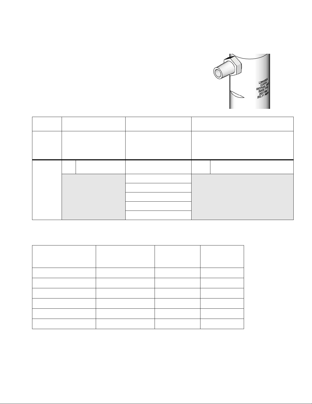
Check your displacement pump’s identification marking for the 6-digit part
number. Use the following matrix to define the construction of your displacement pump. For example, displacement pump model LW025A represents a
wet-cup style stainless steel displacement pump, 25 cc, with a Chromex
coated rod and 3 UHMWPE, 2 PTFE packings.
To order replacement parts, see Parts section starting on page 9. The digits in
the matrix do not correspond to the reference numbers in the Parts drawings
and lists.
LW 025 A
Third, Fourth, and Fifth
Digits
First Digit
Second Digit
(Description)
(Displacement Pump
Volume Per Cycle* in cc)
(Packings; Displacement Rod Coating)
Sixth Digit
Models
ti12415a
L
(Lower)
W
Wet-cup style,
stainless steel
025 A
050
075
100
125
150
* Cycle refers to combination of one upstroke and one downstroke.
Maximum Working
Pressure
Model, Series
LW025A, Series A
LW050A, Series A
LW075A, Series A
LW100A, Series A
psi (MPa, bar) Fluid Inlet Fluid Outlet
3000 (20.7, 207) 1/2 in. npt 3/8 in. npt
4500 (31.0, 310) 3/4 in. npt 3/8 in. npt
4800 (33.1, 331) 3/4 in. npt 3/8 in. npt
3600 (24.8, 248) 3/4 in. npt 3/8 in. npt
3 UHMWPE, 2 PTFE; Chromex™
LW125A, Series A
LW150A, Series A
312792F 3
2900 (20.0, 200) 1 in. npt 1/2 in. npt
2400 (16.5, 165) 1 in. npt 3/4 in. npt
Component Identification
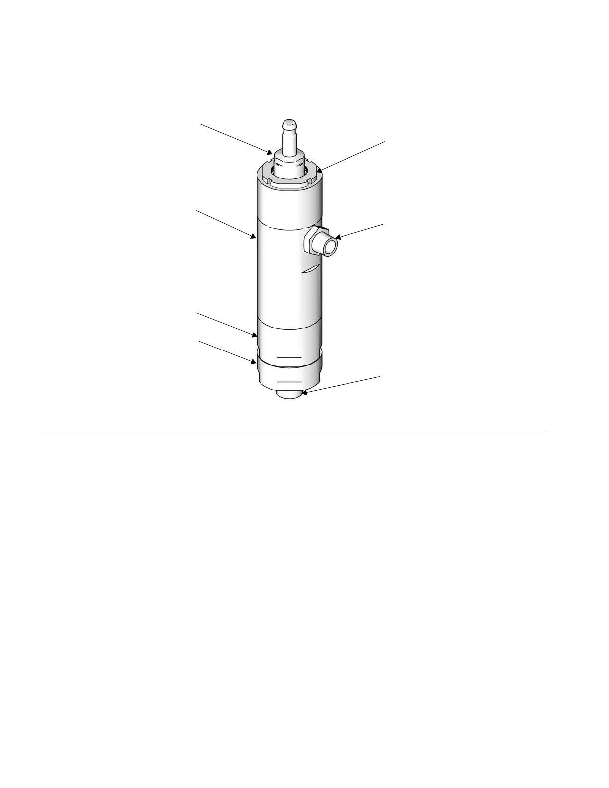
Component Identification
A
F
E
B
C
FIG. 1. Component Identification
Key:
A Piston/Rod Assembly
BWet Cup
C Fluid Outlet
D Fluid Inlet
E Lower Cylinder
F Upper Cylinder
G Intake Valve
G
D
ti11645a
4 312792F
Repair
General Information
Repair
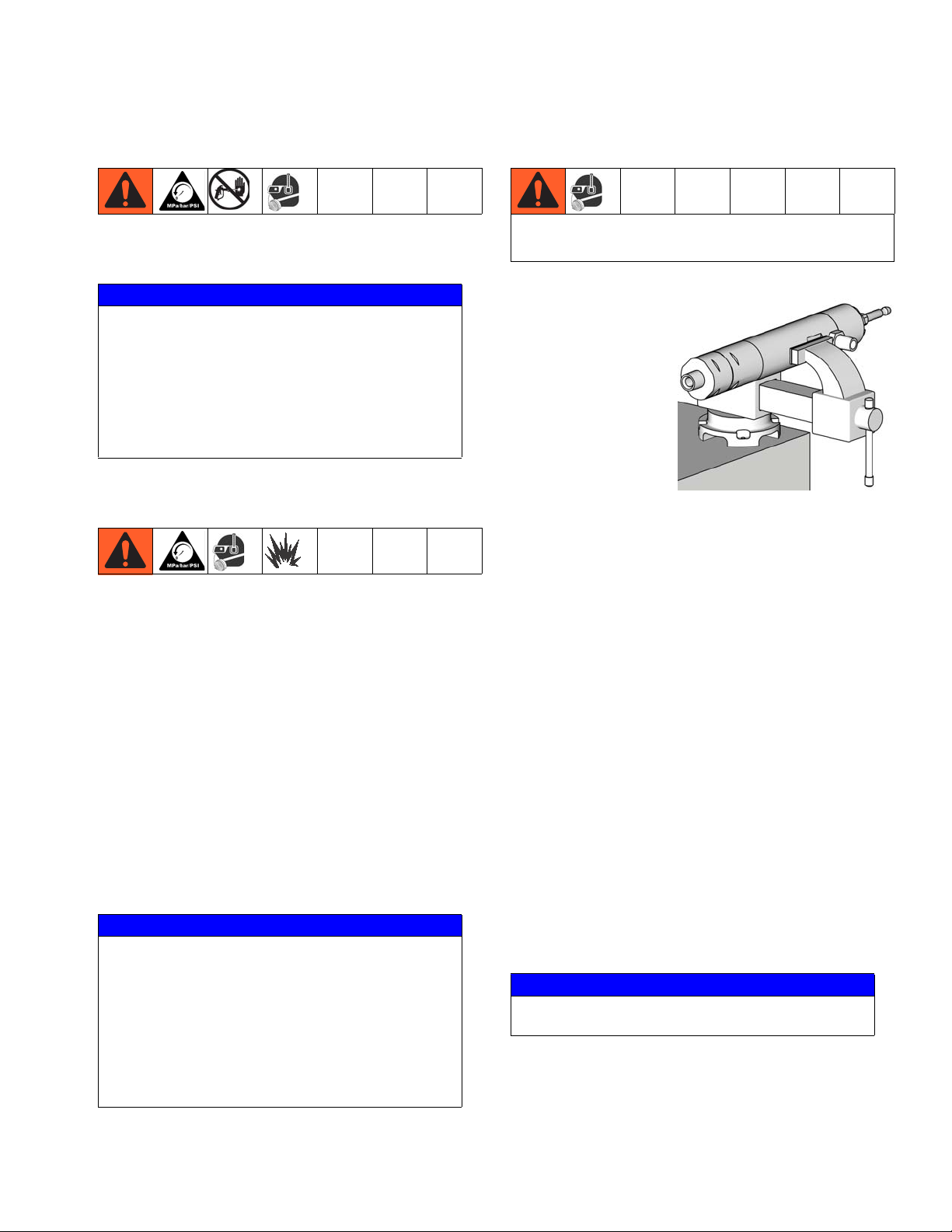
Threads are very sharp. Use a rag to protect hands.
NOTICE
Reference numbers and letters in parentheses in the
text refer to the callouts in the figures and the parts
drawing.
Always use Genuine Graco Parts and Accessories,
available from your Graco distributor. If you supply
your own accessories, be sure they are adequately
sized and pressure rated for your system.
Preparation
Follow all warnings and instructions in your pump manual for the following preliminary steps:
1. Flush the equipment.
2. Relieve the pressure.
3. Remove the displacement pump from the pump
assembly.
1. Place cylinder (1)
sideways in a
vise with soft
jaws.
2. Use an adjustable
wrench on hex of
intake housing
(23) to unscrew it
from the lower
cylinder (2).
Loosen vice
briefly and tip out
the ball (24◆).
3. Remove the seat (22†) and use an o-ring pick to
remove the seal (26†) from the intake housing. See
F
IG. 7.
4. Use an adjustable wrench on hex of lower cylinder
(2) to remove it from the upper cylinder (1) and slide
it straight off the pump. Be careful not to damage
the piston/rod assembly (3).
5. Remove the o-ring (21*†) from the top of the lower
cylinder.
ti12918a
6. Loosen the wet cup (5).
Disassembly
Lay out all removed parts in sequence to ease
reassembly. Clean all parts with a compatible solvent
and inspect them for wear or damage.
NOTICE
Repair Kits are available. See the chart on page 11
to order the correct kit(s) for your pump.
• Parts included in the Seal Repair Kit are marked
with an *, for example 8*.
• Parts included in the Seat Repair Kit are marked
with a †.
• Parts included in the Check Ball Kit are marked
with a ◆.
312792F 5
7. Pull the piston/rod assembly out the bottom of the
upper cylinder. Remove the spring (10*), piston
packings (12* and 13*) and glands (11* and 14*).
8. Remove the wet cup (5).
9. Remove the throat packings (7*, 8*) and glands (6*,
9*) from the bottom of the wet cup.
NOTICE
The jam nut can remain attached to the upper cylinder.
10. Remove the spring (4*) from the top of the upper
cylinder (1).
 Loading...