


R2600
Table of contents
 Loading...
Interface description
R2600 / R2601
DIN Draft 19244 Interface
3-348-815-15
6/11.03


CONTENTS Page Page
1 General ...................................................................................... 4
1.1 Interface hardware ............................................................. 4
1.2 Communications protocol ................................................... 4
1.3 How to connect the interface .............................................. 5
1.4 Principal function ............................................................... 6
1.5 Time action ....................................................................... 7
2 Telegram structure ..................................................................... 8
2.1 Short set ........................................................................... 8
2.2 Control set ........................................................................ 9
2.3 Long set .......................................................................... 10
2.4 Function and value range of the format characters ............. 11
2.5 Criteria for the validity of a request telegram ...................... 14
3 Telegram contents R2600/01 .................................................... 15
3.1 Equipment reset .............................................................. 15
3.2 Interrogation: Equipment OK? ........................................... 15
3.3 Request for cycle data ...................................................... 16
3.4 Request for event data ..................................................... 17
3.5 Request data from R2600/01 ........................................... 20
3.6 Send data to R2600/01 ................................................... 22
GOSSEN METRAWATT GMBH 3
4 Parameter indices of the equipment parameters ........................ 24
4.1 Temperature parameters ................................................. 24
4.2 Control parameters ......................................................... 28
4.3 Control instructions ......................................................... 29
4.4 Equipment specifications ................................................. 32
4.5 Heating current monitor ................................................... 37
5 Storage operations ................................................................... 38
5.1 Request a record ............................................................ 38
5.2 Send a record ................................................................. 39
GOSSEN METRAWATT GMBH 4
1 General
1.1 Interface hardware
To communicate with a host computer, an SPS, etc., the controllers R2600 / 01 must be equipped with marking F1. In this case, the controllers are
equipped with a serial interface having the following data:
• Level types RS-232 and RS-485 (two-wire)
• Baud rate 9600 bd
• Character format 8 data bits, 1 parity bit, 1 stop bit
• Parity Even
• Maximum number of equipment on the bus: 32
• With RS-485 bus operation, each connected R2600/01 must
have a different interface address (Addr = 0 ... 250)
(see operating instructions 3-348-778-15).
1.2 Communications protocol
The transmission protocol used complies with DIN draft 19244. The R2600 / 01 uses only a partial amount of the defined functions which are
described below.
in the unit selectable
2
3
2
-
S
5
8
4
-
S
R
R
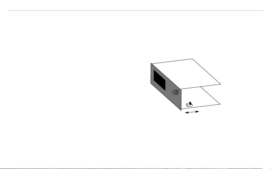
1.3 How to connect the interface
1.3.1 RS-232 connection
When using the a RS-232 interface, only one R2600/01 can be connected to a master (e.g. PC), for example, for pre-loading the unit with user-specific
data.
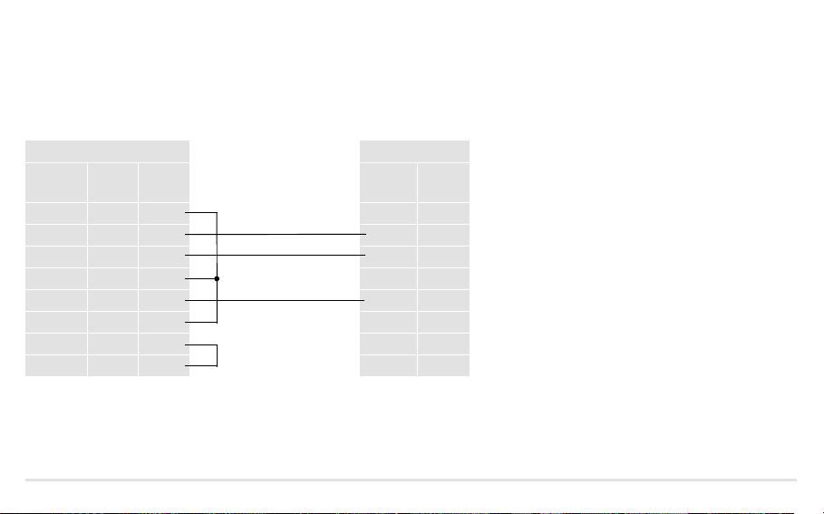
Sub-D socket R2600/01
Number
of pins:
DCD 8 1
RxD 3 2 20 TxD
TxD 2 3 21 RxD
DTR 20 4
Gnd 7 5 19 Gnd
DSR 6 6
RTS 4 7
CTS 5 8
Depending upon the driver software, the jumpers on the master side can be omitted and/or can be different.
GOSSEN METRAWATT GMBH 5
25 9
GOSSEN METRAWATT GMBH 6
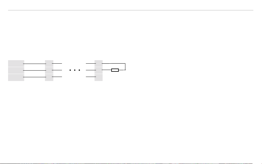
1.3.2 RS-485 connection
When using a RS-485 interface, as many as 32 equipment (R2600/01 and others) can be connected to the bus.
Thereby, all terminals A, B and/or C are interconnected in parallel. The wiring must be made from equipment to equipment and must not be a star connection. With longer bus lines (longer than about 5 m) the bus should be terminated at both ends with the characteristic impedance
(e.g. 200 Ω between A and B).
Master R2600/01 R2600/01
A 21 21
B 20 20
C 19 19
When using the 1799-V5040 interface converter on the master, the following pins are connected on the Sub-D plug:
A = 3 B = 8 C = 5
1.4 Principal function
Involved is a master/slave protocol with a fixedly assigned master (e.g. SPS) and as many as 255 slaves (equipment e.g. R2600/01).
Communication is in half-duplex mode.
An equipment connected to the master becomes active (responds) only, when
– it receives a valid telegram addressed to itself and
– the minimum specified response delay time (t
av) has elapsed so that the host computer has time to get ready to receive data.
Following, the master may only become active again, when
– it receives a reply telegram from the addressed equipment and the specified wait time after a reply telegram (t aw) has elapsed, or
– the maximum specified response delay time (t
av) has elapsed.
Within a telegram, pauses of limited duration (t zv = character delay time) may occur between 2 character transmissions.
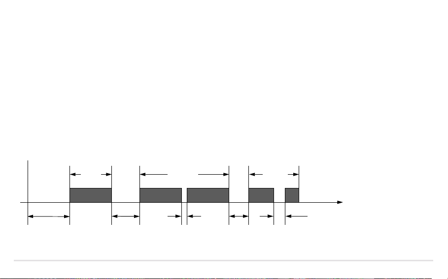
1.5 Time action
Ready to send/receive after turn-on t ber approx. 5 s
Character delay time (R2600 transmitter) t
Character delay time (master) t
Response delay time (R2600 transmitter) 10 ms < t
Wait time after R2600 response (master) t
zvs <3ms
zvm < 500 ms
av < 100 ms
aw > 10 ms
ber
t
approx. 5 s
Master
sends
t
av
10 ...
100 ms
Equipment
responds
tzvs
< 3 ms
taw
> 10 ms
Master
sends
t
zvm
< 500 ms
Time
GOSSEN METRAWATT GMBH 7

GOSSEN METRAWATT GMBH 8
2 Telegram structure
All telegrams consist of one of 3 sets in both request and reply direction, they differ in their principal structure.
Their use is fixed for each interface function of the R2600/01.
Structure and use of the set types are described as follows.
2.1 Short set
Short sets are used on the request side (from the master)
• for transmission of short instructions to the equipment (e.g. Reset)
• for short requests of important data from the equipment (e.g. event data)
Short sets are used on the reply side (from the R2600/01)
• for acknowledgement of requests that require no reply data.
Principal construction short set
Character No. Contents Meaning Remarks
1 10h Start character Especially for short set
2 0 ... FAh, FFh Equipment address Addr and/or 255 (see 2.4.1)
3 Function field (FF) see 2.4.2
4 Checksum (PS) = Equipment address + FFh
5 16h End character Common to all set types

2.2 Control set
The R2600/01 uses control sets on the request side only. They serve to request all equipment data that cannot be requested via a short set because a
detailed specification is required for them.
Principal construction control set
Character No. Contents Meaning Remarks
1 68h Start character
2 3 and/or 6 Length Number of characters from equipment address to checksum exclusive
3 3 and/or 6 Length (repeat)
4 68h Start character (repeat)
5 0 ... FAh, FFh Equipment address Addr and/or 255 (see 2.4.1)
6 Function field (FF) see 2.4.2
7 Parameter index (PI) see 2.4.3
8 1 From channel For reasons of compatibility with multi-channel controllers these charac9 1 To channel
10 0 Receipt number
8 and/or 11
Checksum (PS)
9 and/or 12 16h End character
1) For the set types, the checksum is formed by bytewise summation without overflow summation over all characters from the equipment address to checksum exclusive.
GOSSEN METRAWATT GMBH 9
ters must be available, omitted for parameter index 30h ... 3Fh.
1)

GOSSEN METRAWATT GMBH 10
2.3 Long set
The R2600/01 uses long sets to transmit instructions and parameters to the equipment and to receive data from the equipment.
Principal construction long set
Character No. Contents Meaning Remark
1 68h Start character
2 Length Number of characters from equipment address to checksum
3 Length (repeat)
4 68h Start character (repeat)
5 0 ... FAh, FFh Equipment address Addr and/or 255 (see 2.4.1)
6 Function field (FF) see 2.4.2.
7
8 1
9
10
Parameter index (PI)
From channel
1
0
To c h a nnel
Receipt number
1)
1)
1)
1)
. . . n character data block see 2.4.4.
Length + 5
Checksum (PS)
Length + 6 16h End character
1) Omitted for reply cycle data and event data.
2) For the set types, the checksum is formed by bytewise summation without overflow summation over all characters from the equipment address to checksum exclusive.
exclusive
see 2.4.3.
Omitted for parameter index 30h ... 3Fh
2)

2.4 Function and value range of the format characters
2.4.1 Equipment address
• 0 ... 250 Range for individual equipment addresses = interface address Addr
• 255 All equipment connected to a bus can simultaneously be addressed under this address. Data and instructions entered with this address
are accepted by all equipment, but there is no acknowledgement made to the master.
2.4.2 Function field (FF)
The function field contains
• with the short set the proper user information, predefined by bits and different in request and response direction
• with the control and long set the direction and control information for the transmitted data block
2.4.2.1 Function coding of the function field in request direction
Request check Code Set Remark
Reset equipment 09h
Interrogation: Equipment OK? 29h Short set
Request cycle data from equipment 89h The R2600/01 evaluates the given codes only; an error acknowledgement is
Request event data from equipment A9h
Send data to R2600/01 69h Long set
Request data from R2600/01 89h
GOSSEN METRAWATT GMBH 11
issued for invalid ones

GOSSEN METRAWATT GMBH 12
2.4.2.2 Function coding of the function field (FF) in response direction
Bit No. Function Value Meaning
0 ... 2 Reserved 0, 0, 0 (fixed)
3 Request disable 01Instruction executed, equipment ready
4 Instruction acknowledgement 01Instruction executed, equipment ready
5 Transmission error 01Request telegram correct
6 Not used 0
7 Service request 01None of the errors contained in error status words 1 and 2 occurred
Equipment not ready for this instruction, eventually repeat instruction
Instruction could not be executed, equipment ready
Request telegram incorrect
One or more errors occurred, request error status for exact identification!
Loading...