

Page 1
- 2-2 -
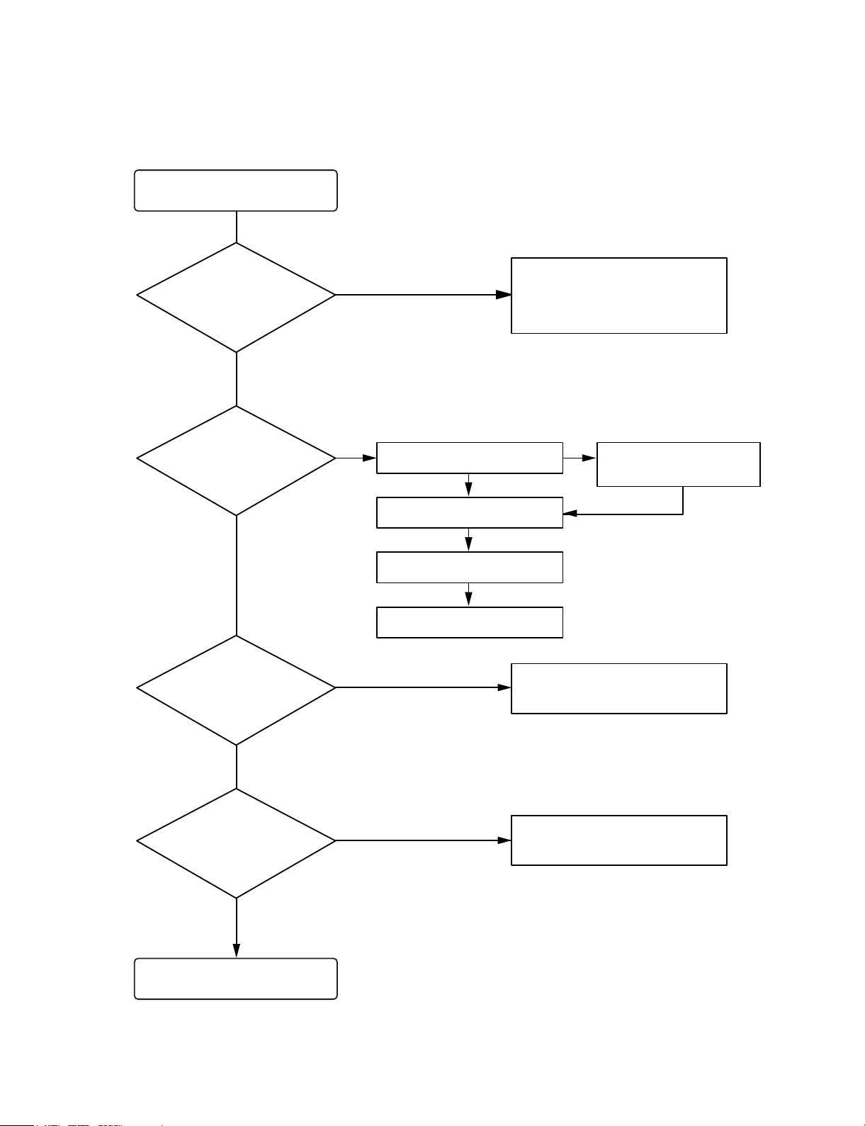
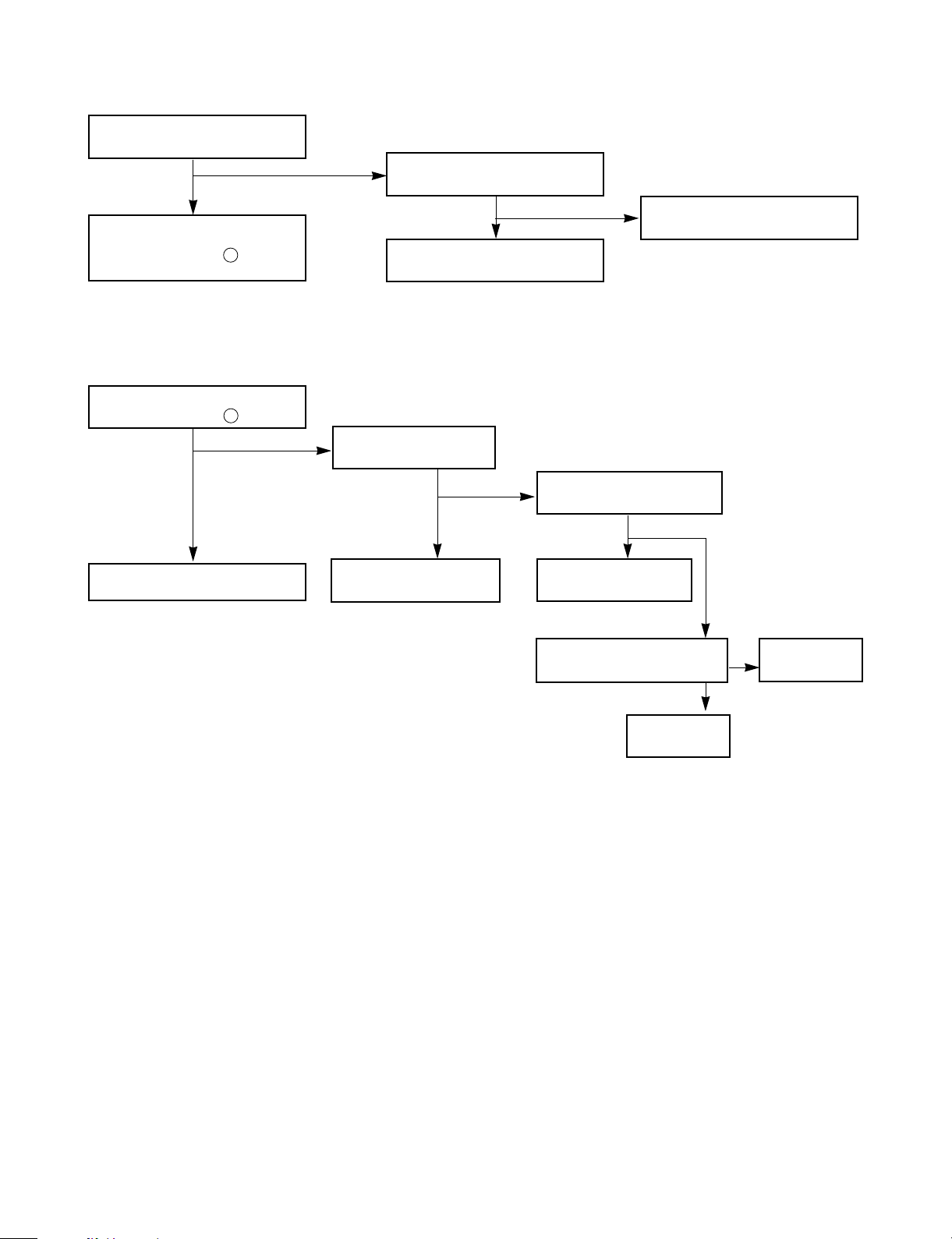
TROUBLESHOOTING
Turn power on.
Is power on?
Does initial read work?
Does it play?
Does it output audio?
Check power supply circuit.
PN508 PIN 8, 6.2V
PN508 PIN 7, 5V
IC503 PIN 2, 3.3V
Check the connector
PN502, PN503, PN507
Check the tracking servo circuit.
Check the PN508 PIN1, 3
OK
YES
YES
YES
YES
YES
YES
YES
YES
NO
NONO
Check the DISK turns
Check the Laser
Check the focus circuit
Check the TRAKING circuit
NO
NO
Page 2
- 2-3 -
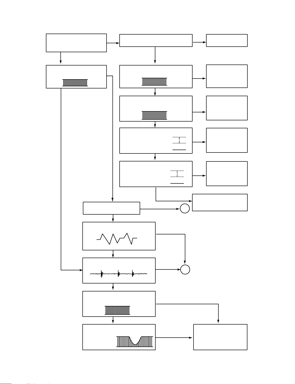
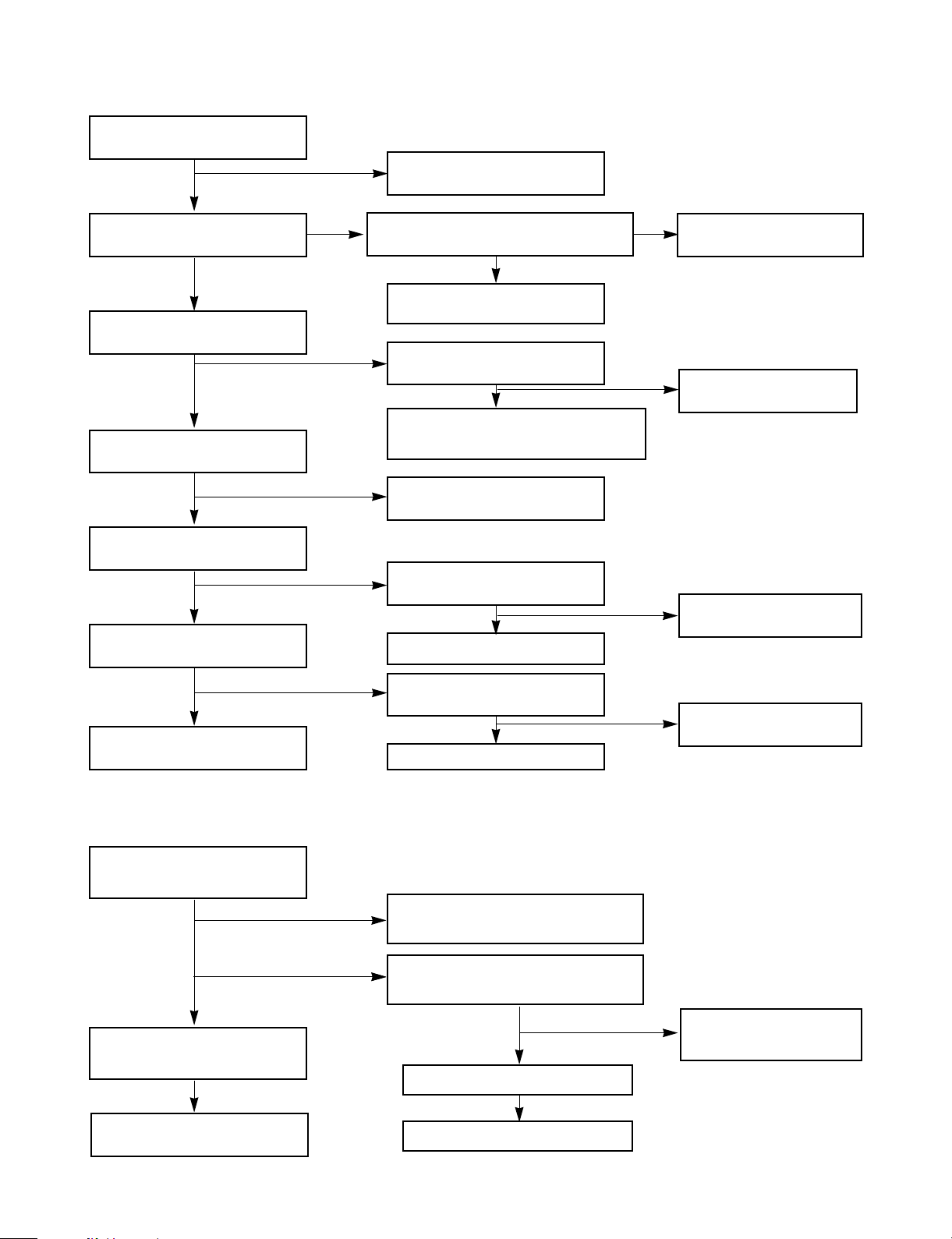
Fails to initial read
A
B
2V
5V
0V
5V
0V
1V
0V
1.2V
0V
0.8V
NO NO
NO
NO
NO
NO
NO
NO
YES
YES
YES
YES
YES
YES
YES
YES
YES
YES
YES
YES
Disc motor turns
Does RF waveform appear?
IC501 Pin4
Check the Data transmission from
PN507 pin8 to CD DSP
Check the Data transmission from
PN507 pin6 to MICOM
Check the change of SLDO
Voltage(IC501 pin23)
Check the change of SL +,
SL - Voltage
(IC502 pin 18, 19)
Check the Voltage change of PN 507
pin2(OPEN, CLOSE)
Defective connector
PN507
Defective connector
PN507 Defective
MICOM
Defective connector
PN507 Defective
IC501
Defective IC501
Defective IC502
Defective contact PN503
Defective PICK-UP
Does laser light?
focus coil drive wareform.
TRACKING ERROR wareform
Is rotation normal?
Defective IC501
Defective PICK-UP
Is there no dropout of RF signal?
Does FA+ waveform appear at
IC502 pin13?
Does TE waveform appear at
IC501 pin 15?
Page 3
- 2-4 -
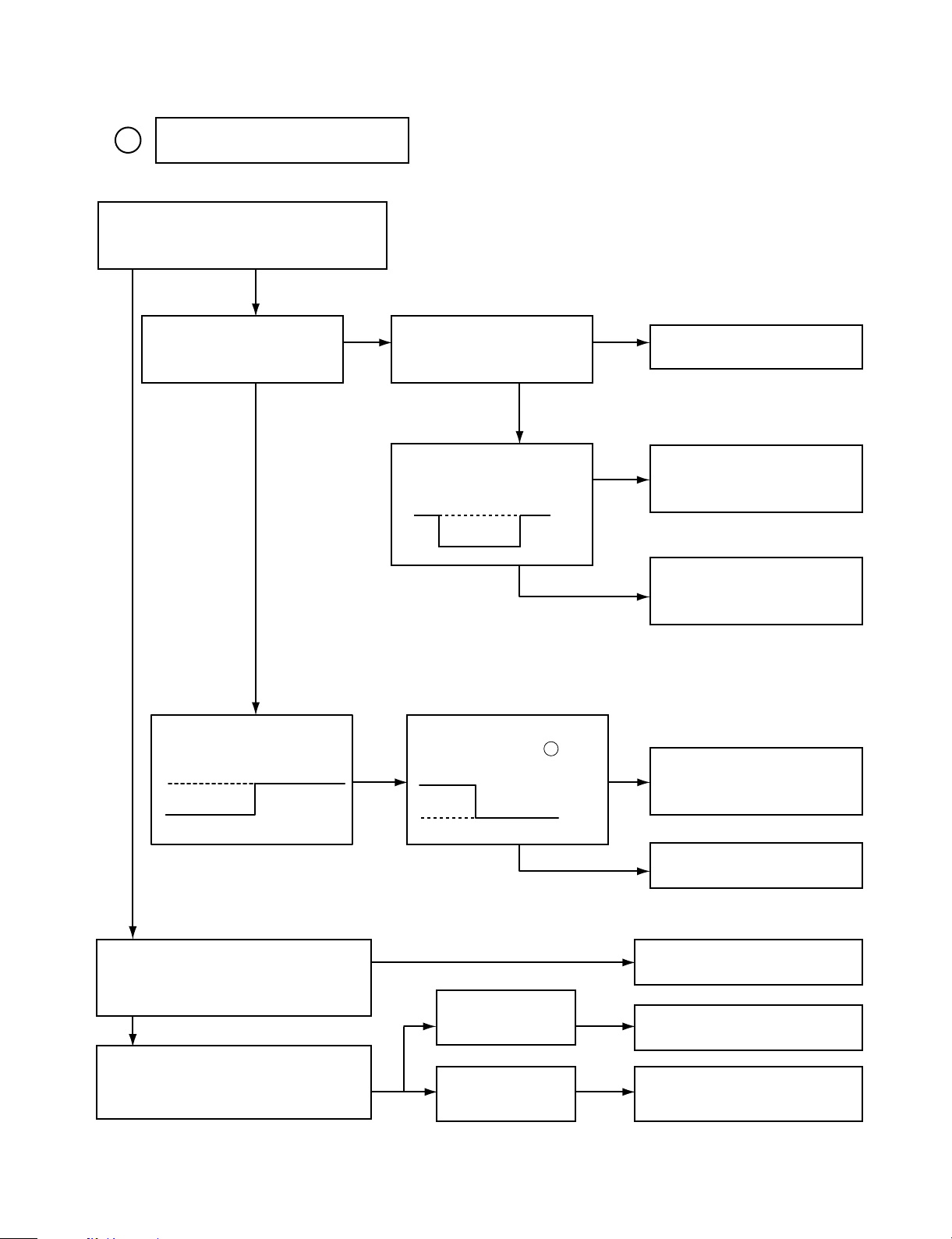
A
NO
NO
NO
NO
NO
NO
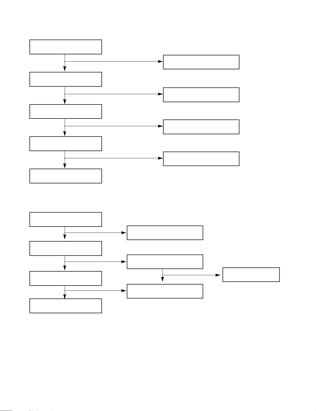
Laser does not light.
Is “3.5V” applied to pin 80 of IC 501?
Is power supplied to laser Q501?
(Q 501 collector: about 1.8V)
Does laser current flow?
1.0V across R508
Is data transferred from
MICOM IC ?
Does voltage appear at IC
502 pin 18,19 ?
Defective MICOM.
Defective MICOM.
Defective connector.
Defective IC 501, 502
Defective slide motor and/or
connector.
Defective LMT SW and/or
connector.
Defective Q 501 and/or laser.
Defective laser and/or
connector.
Did pickup return to
innermost circular?
Does it stop at inner pick
circular after shift?
Is defect output from LM
SW applied to pin of
PN503?
R508»1.0V
R508«1.0V
YES
YES
YES
YES
OPEN
CLOSE
YES
YES
YES
YES
YES
YES
5
Page 4
- 2-5 -
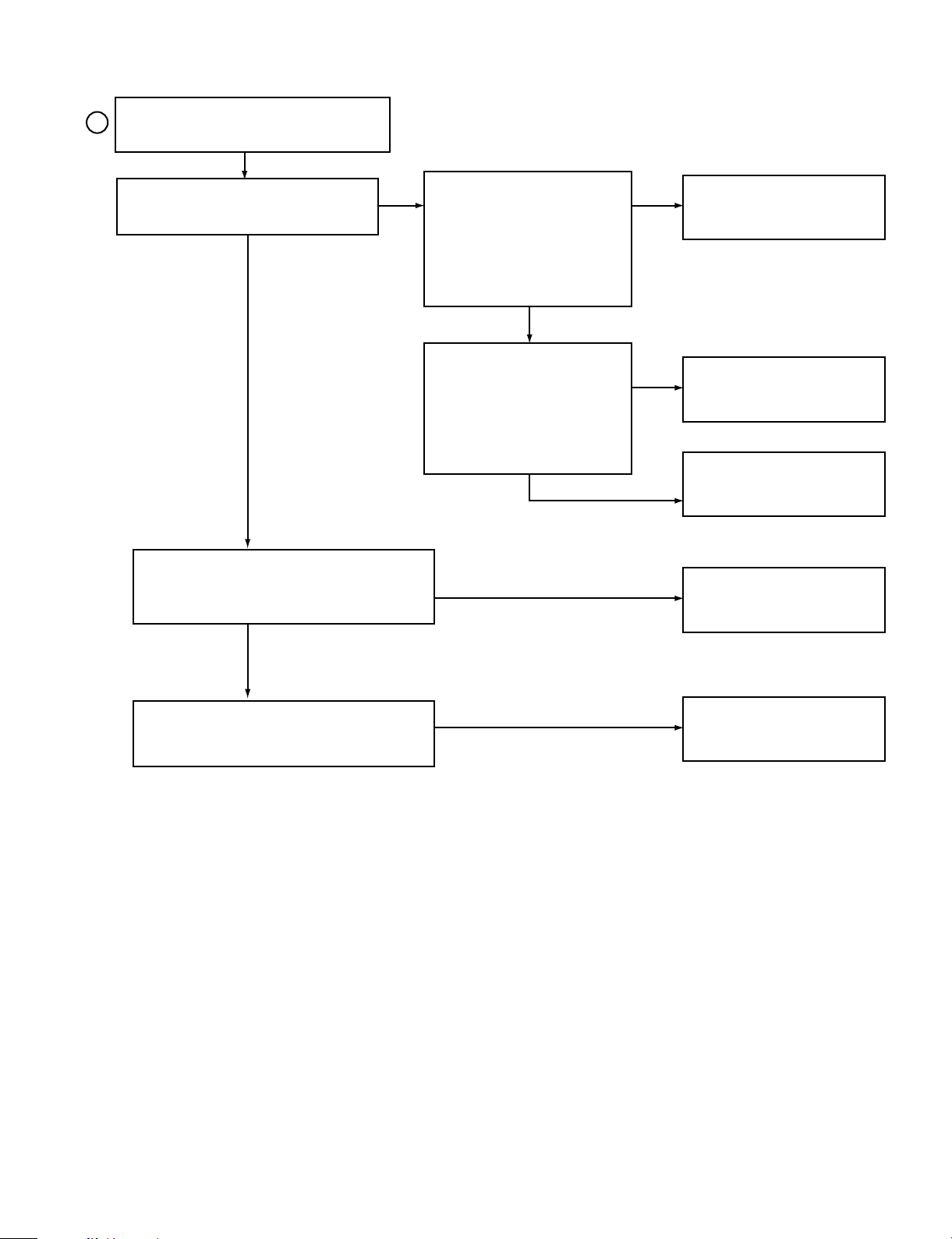
B
NO
NO
NO
NO
NO
YES
YES
YES
YES
Laser lights
Does lens move up/down?
Check the signal of
FOCUS SEARCH
(IC501 Pin 21)
Chekc the signal of PN502
pin 13, 14
Does FE signal appear?
(IC501 pin 13)
Does DRF signal appear? (IC 501 pin67)
Defective IC501
Defective IC502
Open activator and/or connector
Defective IC501
Degraded laser diode
Defective PICK-UP
Page 5
- 2-7 -
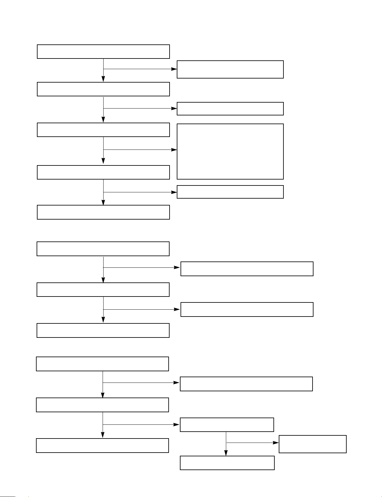
VKK PART
Does DC - 27V appear at
PN301 Pin .
END
Dose -27V appear at
ZD801(-)
Check the Q801
TURN ON
Check the -27V (LOW)
of C773(-)
Replace the D801
Replace the D801, D802
Check the
power
END
YES
YES
YES
YES
NO
NO
NO
NO
P-SENS PART
Does +5V appear at ZD702?
Check the pattern of
IC301 Pin .
Check the waveform
of D706 (+).
Check the R718 and
replace ZD703.
Replace the D706
YES
YES
NO
NO
26
20
Page 6
- 2-8 -
Power Circuit
Muting circuit (MUTE)
Check the Fuse
Check the DC output
of C608(+), C609(-)
Check the DC 12V
Output of IC602, IC603
Check the DC 6.2V
output of IC601
Check the DC 12V
Output of IC601
Check the 5.6V of Q704 “C”
(CD FUNCTION)
END
Dose “High” appear at
Q701, Q751“B”
check the “Low” of Q701,
Q751, “C”
MUTE
Replace the Fuse
Check the power
Check the D611, D612
Replace the IC703
Replace the D606, D607,
D608, 609
Replace the D611, D612
Check the D602, D610
Check the “High” of
IC703 pin4
Check the “High” of Q705“B”
Refer to “IC 203 Troubleshooting
(ONLY Q201/251)
Check the “Low” of the Q702 “B”
Check the “HIGH” of Q702, “E”
Replace the Q702
Refer to IC 301
Troubleshooting
Replace the Q704
Replace the Transformer
Replace the Transformer
Check the “LOW” Voltage
of IC401 Pin 8
Refer to IC401
Troubleshooting
YES
YES
YES
YES
YES
YES
YES
YES
YES
YES
YES
YES
YES
YES
NO
NO
NO
NO
NO
NO
NO
NO
NO
NO
NO
NO
NO
Page 7
- 2-9 -
Audio abnormal
SPK Relay Troubleshooting
Check the output of
IC701 Pin 6, 10
Check the connecting to
SPEAKER
Check the 0.6V of Q710 “B”
Check the input terminal of
Function
OK
Check the output of IC 703
Check “High” of IC400 pin 5
Check the CLOCK of
IC400 PIN 2, 3
Replace the REPLAY(RY710)
Check the input of
IC701 Pin 1, 15
Check the DC10V of IC400
pin24
Check the DC 12V Output of
IC702
Check the power
Check the 12V of R71
Check the High of Q710 “B”
Check the output
END
YES
YES
YES
YES
YES
YES
YES
YES
NO
NO
NO
NO
NO
NO
NO
NO
Page 8

- 2-10 -
FUNCTION MODE Audio abnormal
TAPE
Check the signal input of IC400 pin 7, 28
Refer to “IC201 Troubleshooting”
AUX
Chekc the signal input of IC400, pin 1, 6
Check the signal input of JK705
Check the signal input of IC400 pin 3, 4
Check the signal of PN599 pin 6, 8 or
Refer to “CD Troubleshooting”
Check the signal input of IC400 pin 2, 5
Refer to “IC102 Troubleshooting”
CD
Tuner
Page 9

- 2-11 -
Refer to “IC301
Troubleshooting”
IC301 Troubleshooting
IC400 Troubleshooting
Check the power supplying IC301 Pin 17, 46, 72, 90?
Refer to “Power Circuit Troubleshooting”
Check the P-SENS
Replace the X301
Check the RESET circuit
Refer to “Power Circuit Troubleshooting”
Check the Data of IC301 Pin 9, 10
(CD ➞ TAPE FUNCTION)
Replace the
IC400
Check the pattern
of (IC301 & IC400)
Check the P-SENS “High” of IC301 pin 26
Check the oscillation of X301
When power supplying to IC301 pin11.
(Low ➞ High)
Replace the IC301
Check the power supplying to IC400 pin24
Check the CLK Data of IC400 pin 21, 22
Check the CONTROLL function
END
YES
YES
YES
YES
YES
YES
YES
NO
NO
NO
NO
NO
NO
NO
Page 10

- 2-12 -
FM (TUN101)
Check the +12V input of TUN101 B+ 6
Check the “High” Voltage of TUN101 VT 5
Check the OSC waveform of TUN101 Pin 8
Refer to “IC102 Troubleshooting”
Check the 12V of Q102 “E”
Refer to “Power
Circuit Trouble-
shooting”
Check the “LOW” of IC103 Pin 7
Refer to “IC103
Troubleshooting”
Replace the Q102
Replace the TUN101
Replace the TUN101
YES
YES
YES
YES
YES
NO
NO
IC102 Troubleshooting
Check the power supplying to pin8
Check the waveform of Pin 20, 21
Check the waveform output of Pin 16, 17
END
Refer to “Power Circuit
Troubleshooting”
Check the FM(TUN101) & AM(L107)
Replace the IC102
Replace the IC102
Check the “Low” of Pin 13
Refer to “IC103
Troubleshooting”
YES
YES
YES
YES
NO
NO
NO
NO
NO
Page 11
- 2-13 -
IC103 Troubleshooting
Check the power supplying to pin 17
Check the oscillation of X104
Check the clock of CE, DI, DO, CLK
Is the normal ?
END
Refer to “Power Circuit
Troubleshooting”
Replace the X104
Check the line orrefer to “IC 301
Troubleshooting”
CE: Chip Enable
DI: Data Input(from u-com)
DO: Data Output(to u-com)
CLK: Tuner mode clock
Replace the IC103
YES
YES
YES
YES
NO
NO
NO
NO
AM•COIL Troubleshooting
Check the “High” of L107 Pin 2
Refer to “IC103 Troubleshooting”
Replace the L107
Check the oscillation of L107 Pin 13
Refer to “IC102 Troubleshooting”
YES
YES
NO
NO
Play
Check the VCC supplying to IC201 pin 4
Refer to “Power Circuit Troubleshooting”
Check the Deck Mecha
Replace the Deck
Mecha.
Replace the IC201
Check the signal output of IC201 pin 3, 6
Check the “LOW” of Q201, Q251, “B”
YES
YES
YES
NO
NO
NO
Page 12

- 2-14 -
REC (Q252, Q202 ON / R273, R223 High)
Check signal supplied to IC203 pin 2, 8 ?
Check the output of IC203 Pin3, 7
Check the “High” of IC203 pin 6
Check the power or Refer to “IC203
Troubleshooting”
Check the power
supplying to C227(+)
Check the oscillation of
Q204, “E”
Check the 0.6V of
Q205 “B”
END
Check the Vcc power of IC203 Pin6
Check the oscillation of L201 pin 1, 3
Replace the DECK
Check the “Low” of Q202,
Q252 “B”
Replace the Q202, Q252
Refer to “IC203
Troubleshooting”
Refer to “Power Circuit
Troubleshooting”
Check the 0.6V of
Q205 “B”
Check the IC401 pin12
or Replace the L203
YES
YES
YES
YES
YES
YES
YES
YES
NO
NO
NO
NO
NO
NO
NO
NO
 Loading...