


221966B.12.04 |
Instructions for Use |
Installation and Servicing |
To b e l e f t w i t h t h e u s e r |
4272 |
100FF 120FF
G.C. No. 41 047 59 |
G.C. No. 41 319 75 |
Fanned Flue Boiler
BS 6332
BS 5258
This is a Cat I2H Appliance
Reference in these instructions to British Standards and Statutory
Regulations/Requirements apply only to the United Kingdom.
For Ireland the rules in force must be used.
The instructions consist of three parts, User, Installation and Servicing Instructions.
The instructions are an integral part of the appliance and must, to comply with the current issue of the Gas Safety (Installation and Use) Regulations, be handed to the user on completion of the installation.
Guarantee Registration
Thank you for installing a new Glow-worm appliance in your home.
Glow-worm appliances' are manufactured to the very highest standard so we are pleased to offer our customers' a Comprehensive First Year Guarantee.
We recommend you complete and return your Guarantee Registration Card as soon as possible.
If this card is missing you can obtain a copy or record your registration by telephoning the Glow-worm Customer Service number 01773 828100.
Our Guarantee gives you peace of mind plus valuable protection against breakdown by covering the cost of:
All replacement parts REGISTER YOUR GLOW-WORM APPLIANCE
|
All labour charges |
FOR 1ST YEAR GUARANTEE PROTECTION |
|
|
|
|
|
All call-out charges |
CALL 0800 073 2142 |
||
|
|
|
||
|
|
|
|
|
|
|
|
|
Glow-worm, |
|
|
|
|
|
|
|
|
Tel: (01773) 828100 |
Nottingham Road, Belper, Derbyshire. DE56 1JT |
|
|
|
General/Sales enquiries: |
|
|
|
|
Fax: (01773) 828070 |
|
|
|
|
Tel: (01773) 824141 Fax: (01773) 820569 |
|
|
|
|
||
|
|
|
|
|
www.glow-worm.co.uk

Important Information
Testing and Certification
This boiler is tested and certificated for safety and performance. It is therefore important that no alteration is made to the boiler, without permission, in writing, from Glow-worm.
Any alteration not approved by Glow-worm, could invalidate the certification, boiler warranty and may also infringe the current issue of the Statutory Requirements, see Section 1.4.
CE Mark
This boiler meets the requirements of Statutory Instrument No. 3083 The boiler (Efficiency) Regulations, and therefore is deemed to meet the requirements of Directive 92/42/EEC on the efficiency requirements for new hot water boilers fired with liquid or gaseous fuels.
Type test for purposes of Regulation 5 certified by: Notified body 0086.
Product/productioncertifiedby: Notified body 0086.
The CE mark on this appliance shows compliance with:
1.Directive 90/396/EEC on the approximation of the laws of the Member States relating to appliances burning gaseous fuels.
2.Directive 73/23/EEC on the harmonization of the Laws of the Member States relating to the electrical equipment designed for use within certain voltage limits.
3.Directive 89/336/EEC on the approximation of the Laws of the Member States relating to electromagnetic compatibility.
INFORMATION FOR THE INSTALLER AND SERVICE ENGINEER.
Under Section 6 of The Health and Safety at Work Act 1974, we are required to provide information on substances hazardous to health.
REFRACTORY CERAMIC FIBRE
This product uses insulation material containing Refractory Ceramic Fibre (RCF), which are man-made vitreous silicate fibres. Excessive exposure to these materials may cause temporary irritation to eyes, skin and respiratory tract, consequently, it makes sense to take care when handling these articles to ensure that the release of dust is kept to a minimum.
To ensure that the release of fibres from these RCF articles is kept to a minimum, during installation and servicing we recommend that you use a HEPA filtered vacuum to remove any dust accumulated in and around the boiler before and after working on the boiler. When replacing these articles we recommend that the replaced items are not broken up, but are sealed within heavy duty polythene bags, clearly labelled as RCF waste. This is not classified as “hazardous waste” and may be disposed of at a tipping site licensed for the disposal of industrial waste. Protective clothing is not required when handling these articles, but we recommend you follow the normal hygiene rules of not smoking, eating or drinking in the work area and always wash your hands before eating or drinking.
INSULATION PADS, GLASSYARN.
These can cause irritation to skin, eyes and the respiratory tract. If you have a history of skin complaint you may be susceptible to irritation. High dust levels are usual only if the material is broken. Normal handling should not cause discomfort, but follow normal good hygiene and wash your hands before eating, drinking or going to the lavatory. If you do suffer irritation of the eyes or severe irritation to the skin seek medical attention.
THERMOSTATS
These contain very small amounts of xylene in the sealed phial and capillary. If broken, under normal circumstances the fluid does not cause a problem, but in case of skin contact, wash with cold water. If swallowed drink plenty of water and seek medical attention
CUT-OFF DEVICES
These contain activated charcoal and a very small amount of chlorodifluormethane in the sealed phial and capillary. If broken, under normal circumstances the fluid does not cause a problem. If there is irritation to the eyes or skin then seek medical attention.
Spare Parts
REMEMBER: When replacing a part on this appliance, use only spare parts that you can be assured conform to the safety and performance specification that we require. Do not use reconditioned or copy parts that have not been clearly authorised by Glowworm.
221966B |
2 |

Important Information
CONTENTS |
DESCRIPTION |
SECTION |
PAGE No. |
|||
|
|
|
|
|
|
|
|
|
|
|
|
|
|
INSTRUCTIONS |
|
Introduction |
|
|
|
3 |
FOR USE |
|
Lighting the Boiler |
|
|
|
5 |
|
|
|
|
|
|
|
INSTALLATION |
|
General Data |
|
1 |
|
6 |
|
Flue Terminal |
|
2 |
|
9 |
|
|
|
|
|
|||
INSTRUCTIONS |
|
Water Systems |
|
3 |
|
10 |
|
|
Flue and Appliance Preparation |
|
4 |
|
13 |
|
|
Boiler Installation |
|
5 |
|
17 |
|
|
Flue Fixing |
|
6 |
|
19 |
|
|
Electrical Connectors |
|
7 |
|
20 |
|
|
Commissioning |
|
8 |
|
21 |
|
|
Instructions to the User |
|
9 |
|
24 |
SERVICING |
|
Servicing |
|
10 |
|
24 |
|
Fault Finding |
|
11 |
|
27 |
|
INSTRUCTIONS |
|
|
|
|||
|
Replacement of Parts |
|
12 |
|
31 |
|
|
|
Spare Parts |
|
13 |
|
34 |
|
|
|
|
|
|
|
Instructions for Use
Introduction
WARNING: It is important that the case (not the controls tray) is not disturbed or removed other than for servicing by a competent person.
The user shall not interfere with or adjust sealed parts.
Please read these instructions and follow them carefully for the safe and economical use of your boiler.
The Ultimate FF series are fanned flue boilers designed to provide central heating and indirect domestic hot water.
The boiler is fully automatic in operation having only one user control, the control thermostat.
Gas Leak or Fault
Turn off the gas emergency control valve immediately. Eliminate all sources of ignition, i.e.smoking, blowlamps, hot air guns etc. Do not operate electrical lights or switches either on or off. Open all doors and windows,ventilate the area.
Electrical Supply Failure
Failure of the electrical supply will cause the burner to go out. Should this occur, operation of the appliance will normally resume after the electrical supply is restored.
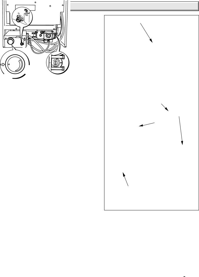
If the boiler does not relight after an electrical supply failure the overheat safety cutoff device may need resetting, remove the controls cover and press the reset button, refer to diagram 1.
IMPORTANT NOTICE
This boiler is for use only on natural gas (G20).
The Gas Safety (Installation and Use)
Regulations
In your interest and that of gas safety it is the law that ALL gas appliances are installed by a competent person in accordance with the above regulations.
Overheat Safety Cutoff
If the overheat safety cutoff device operates on any other occasion than an electrical supply failure, press the reset button as in “Electrical Supply Failure”. If the overheat operates again, turn the appliance off and contact your installation/servicing company.
3 |
221966B |
Instructions for Use
Maintenance
To ensure the continued efficient and safe operation of the boiler it is recommended that it is checked and serviced as necessary at regular intervals. The frequency of servicing will depend upon the particular installation conditions and usage, but in general once a year should be enough.
If this appliance is installed in a rented property in the UK there is a duty or care imposed on the owner of the property by the current issue of The Gas Safety (Installation and Use) Regulations, Section 35.
It is the law that any servicing is carried out by a competent person.
To obtain service, please call your installer or Glow-worm’s own Service Organisation using the telephone number given on the controls tray.
Please be advised that the ‘Benchmark’ logbook should be completed by the installation engineer on completion of commissioning and servicing.
All CORGI Registered Installers carry a CORGI ID card, and have a registration number. Both should be recorded in your boiler Logbook. You can check your installer is CORGI registered by calling CORGI direct on :- 01256 372300.
Boiler Clearances
If fixtures are positioned close to the boiler space must be left as shown in diagram 2. At least a minimum clearance of 500mm must be left in front of the boiler to allow for servicing.
Boilers Installed in a Compartment or Cupboard
If the boiler is installed in a compartment or cupboard do not obstruct any ventilation openings.
Do not use the compartment or cupboard for storage.
Cleaning
WARNING: This appliance contains metal parts (components) and care should be taken when handling and cleaning, with particular regard to edges.
Clean the casing occasionally by wiping it over with a damp cloth or dry polishing duster.
Do not use an abrasive cleaner.
Boiler Electrical Supply
WARNING: This boiler must be earthed.
The boiler must only be connected to a 230V~50Hz supply protected by a 3A fuse.
All system components shall be of an approved type and shall be connected in accordance with the current issue of BS7671 and any applicable local regulations.
External wiring must be correctly earthed, polarised and in accordance with the relevant standards.
In GB this is BS 6891.
In IE this is the current edition of I.S.813 "Domestic Gas Installations".
Wiring to the boiler must be PVC insulated type to the current issue of BS6500 Table 16, not less than 0.75mm2 (24/0.20mm).
CONTROLS COVER |
4140 |
|
30FF to 60FF Ultimate User Controls illustrated, details for the 70FF to 120FF are different but the controls are the same.
4625 |
VIEWING WINDOW |
DATA & |
|
SERIAL |
|||
|
|||
|
|
||
|
|
NUMBER |
|
|
|
LABEL |
|
|
|
|
|
|
RESET |
|
|
|
BUTTON |
|
CONTROL |
|
THERMOSTAT |
|
KNOB |
GAS SERVICE |
SETTING POINT |
COCK (Shown |
|
Off) |
|
Diagram 1 |
The colours of three core flexible cable are:
Brown - live, Blue - neutral,
Green/yellow - earth.
As the markings on your plug may not correspond with these colours continue as follows:
The cable coloured blue must be connected to the terminal marked “N” or black.
The cable coloured brown must be connected to the terminal marked “L” or red.
The cable coloured green/yellow must be connected to the terminal marked “E”, or green or the earth symbol  .
.
221966B |
4 |

Instructions for Use
To Light the Boiler
WARNING: Sealed Systems
Do not operate the boiler wthout water.
A sealed water system must be filled and pressurised by a competent person.
Only light the boiler when you are sure that the system has been filled and pressurised.
The pressure gauge should show at least 0.7bar, anything less than this figure could indicate a leak and you MUST contact your installation/servicing company.
If there is any doubt about the boiler being full of water consult your installation/servicing company.
ALL SYSTEMS:
Turn the electrical supply on to the boiler and check that all remote controls are calling for heat.
To Turn the Boiler On
Remove the controls cover, by withdrawing it forward and off, see diagram 1.
Turn the control thermostat knob clockwise to any position between MIN and MAX. The maximum temperature setting is about 82oC (180oF), see diagram 1.
The boiler lighting operation is now automatic as follows.
The fan operates, followed by an ignition spark until the pilot is lit. When the pilot is alight the ignition system switches off and the main burner lights. The flames can be seen through the viewing window, see diagram 1.
The main burner will remain alight until switched off by the control thermostat or any remote control.
If the boiler is switched OFF, by hand, wait at least 30 seconds before switching on again.
When the boiler switches off, both the pilot and main burner go out.
The automatic lighting sequence will operate again when heat is required.
Refit the controls cover.
It should be noted that this is a fan flue appliance and fan operation may be heard.
To Turn the Boiler Off
For short periods, turn the control thermostat knob anti-clockwise to “O” Off. To relight, turn the control thermostat knob to any position between “MIN” and “MAX”.
For longer periods, turn the control thermostat knob fully anticlockwise to “O” Off and switch off the electrical supply to the boiler.
To relight follow the lighting sequence given above.
Protection Against Freezing.
If the boiler is to be out of use for any long period of time during severe weather conditions we recommend that the whole of the system, including the boiler, be drained off to avoid the risk of freezing up. Make sure that, if fitted, the immersion heater in the cylinder is switched off.
For the position of the serial number, see diagram 1.
0208M
6mm
 6mm
6mm
500mm
Additional clearances may be required for installation
160mm |
6mm |
|
6mm |
|
6mm |
FRONT
VIEW
65mm
Diagram 2
5 |
221966B |

1 General
B |
|
|
|
|
PUMPED FLOW |
|
|
PUMPED RETURN |
|
|
|
|
|
|
|
|
|
C |
|
|
|
|
|
|
F |
|
|
||
A |
O |
|
|
|
|
|
|
|
|
|
|
|||
|
|
|
|
|
|
|
|
|
|
|
||||
|
|
|
|
|
|
|
|
|
H |
G |
|
|
||
|
|
|
|
|
|
|
|
|
|
|
|
|
||
|
|
|
|
E |
|
|
|
|
|
P |
|
|
|
|
|
|
|
|
|
|
|
|
|
|
|
|
|
|
|
|
D |
|
|
|
|
|
|
|
|
|
|
C |
|
|
|
|
|
|
WATER CONNECTIONS |
|
|
|
L |
|
|
||||
J |
|
|
|
|
|
|
|
|
|
K |
||||
|
|
|
|
28mm COPPER PIPE |
|
|
|
|
|
|
||||
|
|
|
|
|
|
|
|
|
|
|
||||
|
|
|
|
|
GAS CONNECTIONS |
|
|
|
|
|
|
|||
|
|
|
|
|
RC1/2 (1/2 in. BSPT) |
|
|
|
|
|
|
|
||
|
|
|
|
|
|
|
|
|
|
|
|
|
|
L |
|
|
|
|
|
|
|
|
|
|
|
|
M |
|
|
SIDE ELEVATION |
|
|
|
|
|
|
|
|
FRONT ELEVATION |
|
||||
MODEL |
A |
B |
C |
D |
E |
F |
G |
H |
J |
K |
L |
M |
O |
P |
100FF,120FF |
67 |
300 |
58 |
127 |
114 |
450 |
168 |
132.5 |
835 |
772 |
63 |
132 |
43 |
78.5 |
|
|
|
|
|
|
|
|
|
|
|
|
|
Diagram 1.1 |
|
IMPORTANT NOTICE
This boiler is for use on Natural Gas (G20) as distributed in the United Kingdom and Ireland and cannot be used on any other gas. This boiler must be installed by a competent person
ONLY.
This boiler can be used on open vented or sealed water systems.
When used on an open vented system domestic hot water can only be provided by pumped circulation to the indirect cylinder.
Wherever possible, all materials, appliances and components used shall comply with the requirements of applicable British Standards.
Where no British Standard exists, materials and equipment should be fit for their purpose and of suitable quality and workmanship.
Refer to Manual Handling Operations, 1992 regulations.
The Health and Safety at Work Act, Control of Substances Hazardous to Health (COSHH).
The Current I.E.E. Wiring Regulations.
Where no specific instructions are given, reference should be made to the relevant British Standard Code of Practice.
In IE, the installation must be carried out by a competent person and installed in accordance with the current edition of I.S.813 "Domestic Gas Installations", the current Building Regulations and reference should be made to the current ETCI rules for Electrical Installation.
In GB the following Codes of Practice apply:
BS4814, BS6798, BS5440 Part 1 and 2, BS5546 Part 1, BS5449, BS6891, BS6700, BS7074 Part 1 and 2, BS7593, BS7671.
In IE: I.S.813, BS5546, BS 5449, BS 7074, BS 7593.
Manufacturer’s instructions must not be taken as overriding statutory requirements.
Sheet Metal Parts
WARNING: When installing or servicing this boiler care should be taken when handling sheet metal parts, to avoid any possibility of personal injury.
1.1 Statutory Requirements
In GB the installation of the boiler must be carried out by a competent person as described in the following regulations:
The manufacturer’s instructions supplied.
The Gas Safety (Installation and Use) Regulations.
The appropriate Buildings Regulations either The Building Regulations, The Building Regulations (Scotland),The Building Regulations (Northern Ireland).
The Water Fittings Regulations or Water byelaws in Scotland.
1.2 Data
See Table 1
All dimensions are given in millimetres (except as noted).
*NOTE: Lift weight is with Flue Elbow, Controls Cover and Front Cover removed.
The Seasonal Efficiency Domestic Boilers UK (SEDBUK) is Ultimate 100FF = 79, Ultimate 120FF = 78.1.
The value is used in the UK Government’s Standard Assessment Procedure (SAP) for energy rating of dwellings. The test data from which it has been calculated have been certified by B.S.I.
1.3 Range Rating
This boiler is range rated and may be adjusted to suit individual system requirements.
Table 2 gives the ratings and settings.
221966B |
6 |

1 General
DATA TABLE 1. |
|
|
|
9072 |
|
|
|
|
|
|
|
MODEL |
|
100FF |
|
120FF |
|
|
|
|
|||
|
|
|
|
|
|
TOTAL DRY |
|
|
|
|
|
WEIGHT |
|
71.0 kg |
|
71.0 kg |
|
(Including |
|
(157 lb) |
|
(157 lb) |
|
Terminal) |
|
|
|
|
|
|
|
|
|
|
|
* |
|
63.3 kg |
|
63.3 kg |
|
LIFT WEIGHT |
|
(140 lb) |
|
(140 lb) |
|
|
|
|
|
||
|
|
|
|
|
|
WATER |
|
3.8 litres |
|
3.8 litres |
|
CONTENT |
|
(0.84 gal) |
|
(0.84 gal) |
|
|
|
|
|
|
|
GAS |
|
Rc 1/2 in. |
|
|
|
CONNECTION |
|
|
|
|
|
|
|
|
|
|
|
ELECTRICITY |
|
71W |
|
97W |
|
RATING |
|
Internal fuse F1 & F2 (F1A) |
|
||
|
|
|
|
|
|
WATER |
|
2x28mm copper pipes from |
|
||
CONNECTION |
|
top of case |
|
||
|
|
|
|
|
|
ELECTRICITY |
|
230V~50Hz, fused 3A |
|
||
SUPPLY |
|
|
|||
|
|
|
|
|
|
|
|
|
|
|
|
DATA LABEL |
|
Bottom right hand side of case |
|
||
|
|
|
|
|
|
1.4 B.S.I. Certification
This boiler is certificated to the current issue of BS6332 Part 1, invoking the current issue of BS5258 Part 1 for performance and safety. It is, therefore, important that no alteration is made to this boiler without permission, in writing, from Glow-worm.
Any alteration that is not approved by Glow-worm, could invalidate the B.S.I. Certification of the boiler, warranty and could also infringe the current issue of the Statutory Requirements.
1.5 Gas Supply
The gas installation shall be in accordance with the relevant standards.
In GB this is BS6891.
In IE this is the current edition of I.S.813 "Domestic Gas Installations".
The supply from the governed meter must be of adequate size to provide a steady inlet working pressure of 20mbar (8in wg) at the boiler.
On completion test the gas installation using the pressure drop method and suitable leak detection fluid, purge in accordance with the current issue of BS6891.
1.6 Electrical Supply
WARNING: This boiler must be earthed.
All system components shall be of an approved type and shall comply with and be connected in accordance with the current issue of BS7671 and any applicable local regulations.
External wiring must be correctly earthed, polarised and in accordance with the relevant standards.
In GB this is BS 6891.
In IE this is the current edition of I.S.813 "Domestic Gas Installations".
Connection of the boiler and system controls to the mains supply must be through a common isolator and must be fused 3A, maximum. This method of connection must be by a fused double pole isolating switch with a minimum contact separation
TABLE 2. |
100FF |
|
|
|
9715 |
|
|
|
|
||
|
|
|
|
|
|
RANGE RATING |
Min. |
Med. |
Max. |
|
|
|
|
|
|
|
|
NOMINAL |
kW |
26.44 |
29.24 |
32.38 |
|
HEAT |
|
|
|||
|
90,210 |
99,760 |
110,485 |
|
|
INPUT(NETT) |
Btu/h |
|
|||
|
|
|
|
|
|
NOMINAL |
kW |
23.45 |
26.38 |
29.31 |
|
HEAT |
|
|
|||
|
80,000 |
90,000 |
100,000 |
|
|
OUTPUT |
Btu/h |
|
|||
|
|
|
|
||
|
|
|
|
|
|
BURNER. |
m bar |
9.2 |
11.6 |
14.4 |
|
SETTING |
|
|
|||
|
3.7 |
4.7 |
5.8 |
|
|
PRESSURE |
in. wg. |
|
|||
|
|
|
|
||
|
|
|
|
|
|
APPROX. |
m3/h |
2.8 |
3.1 |
3.5 |
|
GAS |
|
|
|||
ft3/h |
100 |
111 |
123 |
|
|
RATE |
|
||||
|
|
|
|
|
|
BURNER INJECTOR MARKING: 205727 |
|
||||
BURNER INJECTOR SIZE: |
4.7mm |
|
|||
|
|
|
|
|
|
TABLE 2. |
120FF |
|
|
|
|
|
|
|
|
||
RANGE RATING |
Min. |
Medium. |
Max. |
||
|
|
|
|
|
|
NOMINAL |
kW |
|
36.52 |
|
|
HEAT |
|
|
|
||
|
|
124,608 |
|
||
INPUT(NETT) |
Btu/h |
|
|
||
|
|
|
|||
|
|
|
|
|
|
NOMINAL |
kW |
|
32.24 |
|
|
HEAT |
|
|
|
||
|
|
110,000 |
|
||
OUTPUT |
Btu/h |
|
|
||
|
|
|
|||
|
|
|
|
|
|
BURNER. |
m bar |
9.9 |
12.0 |
14.2 |
|
SETTING |
|
||||
|
4.0 |
4.8 |
5.7 |
||
PRESSURE |
in. wg. |
||||
|
|
|
|||
|
|
|
|
|
|
APPROX. |
m3/h |
|
3.9 |
|
|
GAS |
|
|
|
||
ft3/h |
|
137 |
|
||
RATE |
|
|
|||
|
|
|
|
||
BURNER INJECTOR MARKING: 205726 |
|||||
BURNER INJECTOR SIZE: |
5.2mm |
||||
|
|
|
|
|
|
of 3mm on both poles. The switch should be readily accessible and preferably adjacent to the appliance. It should supply the appliance only and be easilyidentifiable as so doing.
Alternatively, an unswitched shuttered socket outlet and 3A fused 3 pin plug both to the current issue of BS1363 may be used, provided that they are not used in a room containing a bath or shower.
Wiring to the boiler must be PVC insulated type to the current issue of BS6500 Table 16.
1.7 Contents of Packaging
The boiler is delivered in one pack, refer to Section 4.1 for contents.
Refer to Section 4.2 to check that the flue terminal assembly supplied is suitable.
1.8 Water System
This boiler may be fitted to an open vented or sealed water system.
7 |
221966B |

1 General
It is recommended that plastic pipes for primary pipework should not be used for this boiler.
1.9 Drain
System
A draining tap must be provided at the lowest points of the system which will allow the entire system, boiler and hot water cylinder to be drained.
Draining taps should be to the current issue of BS2879.
Boiler
A draining point is fitted at the bottom right hand side of the heat exchanger.
Cover controls to avoid water damage.
If required remove the combustion chamber front cover to improve access.
1.10 Safety Valve
A safety valve need not be fitted to an open vented system.
1.11 Location
This boiler is not suitable for outdoor installation.
This boiler is suitable for installation in bathroom zones 2 and 3.
The boiler may be installed in any room, although particular attention is drawn to the requirements of BS7671 with respect to the installation of a boiler in a room containing a bath or shower. Any electrical switch should be so positioned that it cannot be touched by a person using the bath or shower. The electrical provisions of the Building Standards (Scotland) Regulations apply to such installations in Scotland.
In GB this is the current I.E.E. WIRING REGULATIONS and BUILDING REGULATIONS.
In IE reference should be made to the current edition of I.S.813 "Domestic Gas Installations" and the current ETCI rules.
The boiler must be mounted on a flat wall which is sufficiently robust to take its total weight.
The boiler may be fitted to a wall made of combustible material.
1.12 Boiler Clearances
Refer to diagram 1.2.
The boiler must be positioned so that at least the minimum operational and servicing clearances are provided.
Additional clearances may be required for installation.
If fixtures are positioned next to the boiler they should be made removable for access to pipework.
Sufficient clearance must be left in front of the boiler for servicing.
1.13 Room Ventilation
The boiler is room sealed and does not require the room or space containing it to have permanent airvents.
1.14 Boilers in a Compartment
Where the installation of the boiler will be in an unusual position, special requirements are needed, the current issue of BS6798 gives detailed guidance on these requirements.
A compartment used to enclose the boiler must be designed and constructed specifically for this purpose. An existing cupboard or compartment modified for the purpose may be used. Details of essential requirements for cupboard or compartment design are given in the current issue of BS6798.
The doorway opening should be of sufficient size to allow for easy removal of the boiler.
Where the boiler is fitted in a cupboard or compartment, permanent high and low level ventilation must be provided. The minimum ventilation areas are given in Table 3.
0208M
6mm
 6mm
6mm
PLAN
VIEW
500mm
Additional clearances may be required for installation
160mm |
6mm |
6mm |
6mm |
FRONT
VIEW
65mm
MINIMUM CLEARANCES FROM WALLS CEILING, FLOOR, CUPBOARD, WORKTOPS, AND INFLAMMABLE MATERIALS
TABLE 3. COMPARTMENT AIR VENTS |
0209M |
|||||
|
||||||
|
|
|
|
|
|
|
VENTILATION |
HIGH LEVEL |
LOW LEVEL |
|
|||
REQUIREMENTS |
VENT AREA |
VENT AREA |
|
|||
|
|
|
|
|
|
|
|
MODEL |
cm2 |
in2 |
cm2 |
in2 |
|
VENTILATION |
|
|
|
|
|
|
100FF |
330 |
51 |
330 |
51 |
|
|
FROM |
|
|
|
|
|
|
ROOM |
|
|
|
|
|
|
|
|
|
|
|
|
|
OR SPACE |
120FF |
396 |
61.5 |
396 |
61.5 |
|
|
|
|||||
|
|
|
|
|
|
|
VENTILATION |
100FF |
165 |
25.5 |
165 |
25.5 |
|
FROM |
|
|
|
|
|
|
OUTSIDE |
|
|
|
|
|
|
|
120FF |
198 |
30.5 |
198 |
30.5 |
|
|
|
|
|
|
|
|
1.15 Timber Frame Building
If the boiler is to be installed in a timber frame building it should be fitted in accordance with the Institute of Gas Engineers document IGE/UP/7/1998. If in doubt seek advice from the local gas undertaking or Glow-worm.
1.16 Heating System Controls
The heating system should have installed: a programmer and room thermostat controlling the boiler.
Thermostatic radiator valves may be installed, however they must not be fitted in a room where the room thermostat is located.
NOTE: For further information, see the current issue of the Building Regulations, approved document L1, and the references:
1)GIL 59, 2000: Central heating system specification (CheSS) and
2)GPG 302, 2001: Controls for domestic central heating
system and hot water. BRECSU.
221966B |
8 |

2 Flue Terminal
NOTE: Detailed recommendations for flues are given in the current issue of BS5440 Part 1.
2.1 Terminal Position
The minimum acceptable siting dimensions for the terminal from obstruction, other terminals and ventilation openings are shown in diagram 2.1. For Ireland the minimum distances for flue terminal positioning must be those detailed in I.S.813 "Domestic Gas Installations".
The terminal must be exposed to the external air, the position allowing free passage of air across it at all times.
Car ports or similar extensions of a roof only, or a roof and one wall, require special consideration with respect to any openings, doors, vents or windows under the roof. Care is required to protect the roof if it is made of plastic sheeting. If the car port consists of a roof and two or more walls, seek advice from the local gas company before installing the boiler.
If the terminal is fitted within 600mm below plastic guttering or painted soffit an aluminium shield 1500mm long should be fitted immediately beneath the guttering or eaves. If the terminal is fitted within 450mm below painted eaves or a painted gutter, an aluminium shield 750mm long should be fitted immediately beneath the guttering or eaves.
2.2 Terminal Guard
A terminal guard is required if persons could come into contact with the terminal or the terminal could be subject to damage.
If a terminal guard is required, it must be positioned to provide a minimum of 50mm clearance from any part of the terminal and be central over the terminal.
A suitable guard, reference Type K3, can be obtained from:
Tower Flue Components Ltd
Morley Road
Tonbridge
Kent
TN9 1RA
0103M
A |
C |
|
|
|
B,C |
B,C |
K |
|
|
|
|
|
A |
|
G |
K |
L L |
|
|
|||
|
M |
K |
||
F |
|
F |
||
|
F |
|
||
G |
E |
A |
|
|
G |
|
G |
||
|
|
G |
|
|
Under Car Port etc.
D |
J |
F |
K |
H,I |
MINIMUM SITING DIMENSIONS FOR |
MINIMUM |
||
FANNED FLUE TERMINALS POSITION |
SPACING in mm |
||
|
|
|
|
A |
DIRECTLY BELOW, ABOVE OR HORIZONTALLY |
|
|
|
TO AN OPENING, AIR BRICK, OPENING WINDOWS, |
||
|
AIR VENT OR ANY OTHER |
|
|
|
VENTILATION OPENING. |
|
300 |
B |
BELOW GUTTER, DRAIN/SOIL PIPE |
|
75 |
C |
BELOW EAVES |
|
200 |
D |
BELOW A BALCONY OR CAR PORT |
|
200 |
E |
FROM VERTICAL DRAIN PIPES AND SOIL PIPES |
25 |
|
F |
FROM EXTERNAL CORNERS |
|
25 |
G |
ABOVE ADJACENT GROUND OR BALCONY LEVEL 25 |
||
H |
FROM A SURFACE FACING THE TERMINAL |
600 |
|
I |
FACING TERMINALS |
|
1200 |
J |
FROM OPENING (DOOR/WINDOW) IN |
|
|
|
CAR PORT INTO DWELLING |
|
1200 |
K |
VERTICAL FROM A TERMINAL |
|
1500 |
L |
HORIZONTALLY FROM A TERMINAL |
|
300 |
M |
FROM INTERNAL CORNERS |
|
25 |
4307
Diagram 2.1
9 |
221966B |

3 Water Systems
The installation of the boiler must comply with the requirements of the current issue of BS6798, in Ireland, refer also to the current edition of I.S.813 "Domestic Gas Installations".
In GB it is necessary to comply with the Water Supply (Water Fittings) Regulations 1999 (for Scotland, the Water Byelaws 2000, Scotland).
To comply with the Water regulations your attention is drawn to: The Water Regulations guide published by the Water Regulations Advisory Service (WRAS) gives full details of the requirements.
In IE the requirements given in the current edition of I.S.813 "Domestic Gas Installations" and the current Building Regulations must be followed.
It is recommended that plastic pipes for primary pipework should not be used for this boiler.
3.1 Frost Protection
If the position of the boiler is such that it may be vulnerable to freezing it should be protected as specified in the current issue of BS5422. It is recommended that a frost protection thermostat be fitted.
3.2 Pump
The pump, with integral valves, should be fitted in the heating flow pipework from the boiler, it should be set to produce a temperature difference of 11oC (20o), between the flow and return, with the control thermostat set at “MAX”, which is about 82oC (180oF).
The pressure loss of the boiler can be found from diagram 3.1.
High resistance microbore systems may require a higher duty pump.
3.3 Bypass - Fully Pumped and Sealed Water
System
A bypass MUST be fitted to a fully pumped and sealed water system.
Where the water system allows the boiler and pump to operate on bypass only, the bypass connection must be at least 2.5metres away from the boiler.
The flow through the boiler must not be allowed to fall such that there is a temperature difference greater than 20oC between the flow and return.
3.4 Water System
For an open vented system the boiler must be supplied from an unrestricted water supply taken from a feed and expansion cistern fitted at a maximum height of 27metres above the boiler.
The cold feed must be 15mm minimum size.
It is important that the relative positions of the pump, cold feed and open vent are as shown in diagram 3.2.
The unrestricted open vent from the boiler must rise continuously to over the feed and expansion cistern.
3.5 Domestic Hot Water System
General - All domestic hot water circuits, connections, fittings must be in accordance with the relevant standards and water supply regulations.
For GB: Guidance G17 to G24 and recommendation R17 to R24 of the Water Regulations Guide.
For IE: The current edition of I.S.813 "Domestic Gas Installations".
The domestic hot water service must be in accordance with the current issue of BS5546, refer also to the current issue of BS6700.
|
|
750 |
|
|
|
|
|
|
|
|
|
|
|
|
|
|
|
|
|
|
|
|
|
|
|
|
|
|
|
|
|
|
|
|
|
pressureWaterloss |
water)ofhead(mm |
|
|
|
700mm |
|
(120FF |
|
) |
|
|
|
|
|
|
|
|
500 |
|
|
|
|
|
|
|
|
|
|
|
|
|
|
|
||
|
|
|
|
|
|
|
|
|
|
|
|
|
|
|
|
|
|
|
|
|
|
|
|
|
|
|
|
|
|
|
|
|
|
|
|
|
|
|
|
|
450mm |
|
(100FF |
|
) |
|
|
|
|
|
|
|
|
|
|
250 |
|
|
|
|
|
|
|
|
|
|
|
|
|
|
|
|
|
|
|
|
|
|
|
|
|
|
|
|
|
|
|
|
|
|
|
0 |
|
|
|
|
|
|
|
|
|
|
|
|
|
|
|
|
|
|
|
|
|
|
|
|
|
|
|
|
|
|
|
||
|
|
|
|
|
|
|
|
|
|
|
|
|
|
|
|
|
|
0 |
5 |
10 |
15 |
20 |
25 |
30 |
35 |
40 |
45 |
0088(z)M |
|
|
Flow rate (litres/minute) |
|
|
||||
|
|
|
|
|
|||||
|
|
Design Flow Rate |
|
|
|
|
|||
|
|
|
|
|
|
|
|
||
PRESSURE LOSS |
|
|
|
|
|
|
|
||
OF BOILER 100FF/120FF |
|
|
|
Diagram 3.1 |
|||||
3.6 Indirect Cylinder
For all systems supplying domestic hot water the cylinder must be indirect. It is recommended that the indirect cylinder be fitted with some form of temperature control.
3.7 Fully Pumped Heating and Domestic Hot
Water
The connections for this type of system MUST be as shown in diagram 3.2 and 3.3.
3.8 Inhibitor
Attention is drawn to the current issue of BS5449 and BS7593 on the use of inhibitors in central heating systems.
If an inhibitor is to be used, contact a manufacturer or Glowworm, for their recommendations as to the best product to use.
When installing in an existing system take special care to drain the entire system, including the radiators, then thoroughly cleaning out before installing the boiler whether or not adding an inhibitor.
3.9 Sealed Water Systems
The installation should comply with the appropriate requirements of the current issue of BS4814, BS5449, BS6759, BS6798 and BS7074 Part 1 and 2, see diagram 3.4 for a suggested layout.
3.10 Safety Valve
A safety valve must be fitted to a sealed water system.
It shall be preset, nonadjustable with a lift pressure of 3bar, incorporating seating of resilient material, a test device and a connection for drain.
The drain from the safety valve must be routed clear of any electrical fittings and positioned so that any discharge can be seen.
221966B |
10 |
3 Water Systems
OPEN VENTED FULLY PUMPED WATER SYSTEM |
6349 |
|||
RECOMMENDED RELATIONSHIP BETWEEN |
|
|
||
PUMP COLD FEED AND VENT |
|
|
|
|
|
22mm VENT |
|
|
|
450mm |
(MIN.) |
|
|
|
MIN. |
FEED AND |
|
|
|
HEIGHT |
|
|
|
|
|
EXPANSION |
|
|
|
|
CISTERN |
|
|
|
|
15mm (MINIMUM) |
|||
|
COLD FEED |
|
|
|
1150mm |
RETURN |
FLOW |
|
|
MIN. |
|
|
|
|
|
CYLINDER |
|
|
|
|
PUMP |
|
HEATING |
|
There must |
FLOW |
|
||
|
|
|||
always be a |
|
|
||
150mm |
|
|
|
|
cold water |
MAX. |
|
|
|
path to the |
|
|
|
|
return |
RET. |
|
|
|
connection |
|
|
||
|
|
|
|
|
of the boiler. |
28mm (MINIMUM) |
|
||
BOILER
BY-PASS WITH
LOCKSHIELD VALVE
Diagram 3.2
3.11 Expansion Vessel
A diaphragm type expansion vessel, conforming to the current issue of BS4814 (see also BS7074 Part 1 and 2) must be connected at a point close to the inlet side of the circulating pump, see diagram 3.4, unless laid down differently by the manufacturer.
The expansion vessel volume depends upon the total water system volume and the initial system design pressure. For any system an accurate calculation of vessel size is given in the current issue of BS5449 and BS7074 Part 1, for IE refer to the current edition of I.S.813 "Domestic Gas Installations".
Example. For an initial system design pressure of 0.7bar the minimum total vessel volume required is 0.063xTotal System volume.
NOTE: A higher initial design pressure requires a larger volume expansion vessel.
The charge pressure must not be less than the static head of the system, that is, the height of the highest point of the system above the expansion vessel.
The water content of the boiler is given in Data Table 1.
3.12 Pressure Gauge
A pressure gauge with a set pointer and covering at least the range of 0 to 4bar (0 to 60lb/in2) shall be permanently fitted to the system in a position where it can be seen when filling the system.
FLOW |
RETURN |
4273 |
|
|
|
||
|
|
|
|
|
|
|
|
28mm PIPE
22mm VENT & 15mm COLD FEED TO BE FITTED IN ACCORDANCE WITH BS 5449
6459
INDIRECT
CYLINDER
1metre Min.
27 metres BYPASS 28mm Max. MIN WITH
LOCKSHIELD VALVE
HEATING


 SYSTEM PUMP

 ALTERNATIVE
SYSTEM
CONTROL
VALVES
FULLY PUMPED CIRCULATION
BYPASS (DIAGRAMMATIC)
22mm FOR COMBINED FEED & VENT TO BE FITTED IN ACCORDANCE
WITH BS 5449 |
6466 |
|
INDIRECT
CYLINDER
1metre Min. |
BYPASS 28mm |
|
||||||
27 metres |
MIN WITH |
|
||||||
Max. |
|
|||||||
LOCKSHIELD |
|
|||||||
|
|
|
|
|||||
|
|
|
VALVE |
|
||||
|
|
|
|
|
|
|
|
HEATING |
|
|
|
|
|
|
|
|
|
|
|
|
|
|
|
|
|
SYSTEM |
|
|
|
|
|
|
PUMP |
||
|
|
|
|
|
|
ALTERNATIVE |
||
|
|
|
|
|
|
|
|
|
|
|
|
|
|
|
|
|
|
|
|
|
|
|
|
|
|
SYSTEM |
|
|
|
|
|
|
|
|
CONTROL |
|
|
|
|
|
|
|
|
|
|
|
|
|
|
|
|
|
VALVES |
FULLY PUMPED CIRCULATION |
|
|||||||
BYPASS (DIAGRAMMATIC) |
Diagram 3.3 |
|||||||
|
|
|
|
|
|
|
|
|
11 |
221966B |
 Loading...