


Flexicom cx

Installation
and Servicing
Condensing Boilers/
Flexicom cx
24cx
30cx G.C.No. 47-047-34
35cx G.C.No. 47-047-35
G.C.No. 47-047-33

Guarantee Registration
Thank you for installing a new Glow-worm appliance in your home.
Glow-worm appliances are manufactured to the very highest standard so we are pleased to offer
our customers a Comprehensive Guarantee.
This product is guaranteed for 24 months from the date of installation or 30 months from the date
of manufacture, whichever is the shorter, for parts and labour.
The second year of the parts guarantee, from the beginning of the 13th month onwards after
installation or manufacture, is conditional upon the boiler having been serviced by a competent
person approved at the time by the Health and Safety Executive in accordance with the
manufacturer’s recommendations. We strongly recommend regular servicing of your gas
appliance, but where the condition is not met, any chargeable spare parts or components issued
within the applicable guarantee period still benet from a 12 month warranty from the date of issue
by the manufacturer.
We recommend you complete and return as soon as possible your guarantee registration card.
If your guarantee registration card is missing you can obtain a copy or record your registration by
telephoning the Glow-worm Customer Service number 01773 828100.
Customer Service:
01773 828100
Technical Helpline:
01773 828300
General and Sales enquiries:
Tel. 01773 824639
Fax: 01773 820569
To register your Glow-worm appliance call:
0800 0732142
Benchmark places responsibilities on both manufacturers and installers. The purpose is to ensure that customers are provided
with the correct equipment for their needs, that it is installed, commissioned and serviced in accordance with the manufacturer’s
instructions by competent persons and that it meets the requirements of the appropriate Building Regulations. The Benchmark
Checklist can be used to demonstrate compliance with Building Regulations and should be provided to the customer for future
reference.
Installers are required to carry out installation, commissioning and servicing work in accordance with the Benchmark Code of
Practice which is available from the Heating and Hotwater Industry Council who manage and promote the Scheme.
Visit www.centralheating.co.uk for more information.

TABLE OF CONTENTS
These instructions consist of, Installation, Servicing, Fault Finding, Replacement of Parts
and Spares. The instructions are an integral part of the appliance and must, to comply
with the current issue of the Gas Safety (Installation and Use) Regulations, be handed to
the user on completion of the installation.
CONTENTS DESCRIPTION SECTION PAGE
Warnings 4
Important Information 4
INTRODUCTION
INSTALLATION
Statutory Requirements 5
Boiler Design 6
Safety Devices 6
Servicing, Maintenance and Spare Parts 6
Boiler Specication 1 7
Boiler Dimensions and
Hydraulic Schematic 2 8
Boiler Location, Clearances
and Ventilation 3 9
Evacuation of Combustion Gas 4 10
Water Systems 5 14
Installation Preparation 6 18
Gas/Water Connections 7 20
Boiler Fixing 8 21
Safety Discharge Valve and
Condensate Connections 9 22
Electrical Connection 10 24
Commissioning 11 25
MAINTENANCE
APPENDIX
Servicing 12 29
Fault Finding 13 34
Replacement of Parts 14 40
Spare Parts 15 48
Manual Handling 16 49
Benchmark Logbook 50
Commissioning Flow Chart 53
- 3 -

INTRODUCTION
WARNINGS
Gas Leak or Fault
Turn off the gas emergency control valve immediately. Eliminate all sources of ignition, i.e.smoking, blowlamps,
hot air guns etc. Do not operate electrical lights or switches either on or off. Open all doors and windows,
ventilate the area.
Metal Parts
This boiler contains metal parts (components) and care should be taken when handling and cleaning,
with particular regard to edges.
Sealed Components
Under no circumstances must the user interfere with or adjust sealed parts.
Important Information
Gas Category
This boiler is for use only on G20 natural gas.
Gas Safety (Installation and Use)
Regulations
In your own interests and that of safety, it is the Law that ALL
gas appliances are installed by a competent person approved
at the time by the Health and Safety Executive in accordance
with the current issue of these regulations.
Control of Substances Hazardous to Health
Under Section 6 of The Health and Safety at Work Act 1974, we
are required to provide information on substances hazardous to
health.
The adhesives and sealants used in this appliance are cured
and give no known hazard in this state.
Manual Handling
With regards to the “Manual Handling Operations, 1992
Regulations”, the appliance exceeds the recommended weight
for a one man lift, refer to section 16 for more information.
The handling of the boiler may involve lifting, pushing and
pulling, the use of a sack truck may be required.
The following handling techniques and precautions should be
considered:
- Grip the boiler at its base
- Be physically capable
- Use safety clothing where appropriate, e.g. gloves, safety
footwear.
Ensure safe lifting techniques are used
- Keep back straight.
- Avoid twisting at the waist.
- Avoid upper body/top heavy bending.
- Always grip using the palm of the hand.
- Use designated hand holds.
- Keep load as close to body as possible.
- Always use assistance if required.
Electrical Supply
The boiler MUST be earthed.
All system components shall be of an approved type and all
wiring to current I.E.E. wiring regulations.
External wiring must be correctly earthed, polarised and in
accordance with the relevant standards.
In GB, this is BS 7671.
In IE, this is the current edition of ETCI rules.
The boiler MUST be connected to a permanent 230V ac, 50Hz
supply.
Connection of the whole electrical system of the boiler, including
any heating controls, to the electrical supply MUST be through
one common isolator and must be fused 3 Amp maximum.
Isolation should be by a double pole switched fused spur box,
with a minimum gap of 3mm for both poles. The fused spur
box should be readily accessible and preferably adjacent to the
appliance. It should be identied as to its use.
Alternatively connection can be made through an unswitched
shuttered socket and 3A fused 3-pin plug both to the current
issue of BS 1363, provided they are not used in a room
containing a bath or shower.
Wiring to the boiler must be PVC 85°C insulated cable, not less
than 0.75mm2 (24/0.20mm).
Testing and Certication
This boiler is tested and certicated for safety and performance.
It is, therefore, important that no alteration is made to the boiler,
without permission, in writing, by Glow-worm.
Any alteration not approved by Glow-worm, could invalidate the
certication, boiler warranty and may also infringe the current
issue of the statutory requirements.
- 4 -
0020107232_03 - 12/14 - Glow-worm

INTRODUCTION
CE Mark
This boiler meets the requirements of Statutory Instrument,
No. 3083 The Boiler (Efciency) Regulations, and therefore is
deemed to meet the requirements of Directive 92/42/EEC on
the efciency requirements for new hot water boilers red with
liquid or gaseous fuels.
Type test for purposes of Regulation 5 certied by: Notied
body 0087.
Product/production certied by: Notied body 0086.
The CE mark on this appliance shows compliance with:
1. Directive 2009/142/EC on the approximation of the laws
of the Member States relating to appliances burning gaseous
fuels.
2. Directive 73/23/EEC on the harmonisation of the Laws of
the Member States relating to electrical equipment designed for
use within certain voltage limits.
3. Directive 89/336/EEC on the approximation of the Laws of
the Member States relating to electromagnetic compatibility.
IMPORTANT
Where no British Standards exists, materials and equipment
should be t for their purpose and of suitable quality and
workmanship.
The installation of this boiler must be carried out by a
competent person approved at the time by the Health and
Safety Executive in accordance the rules in force in the
countries of destination.
Manufacturer’s instructions must not be taken as overriding
statutory requirements.
Statutory Requirements
In GB, the installation of the boiler must comply with the
requirements of the current issue of BS6798 and be carried out
by a competent person, approved at the time by the Health
and Safety Executive, as described in the following regulations:
The manufacturer’s instructions supplied.
The Gas Safety (Installation and Use) Regulations.
The appropriate Buildings Regulations either The Building
Regulations, The Building Regulations (Scotland),The Building
Regulations (Northern Ireland).
The Water Supply (water ttings) Regulations 1999 and water
byelaws 2000, Scotland.
The Health and Safety at Work Act, Control of Substances
Hazardous to Health (COSHH).
The Current I.E.E. Wiring Regulations.
Where no specic instructions are given, reference should be
made to the relevant British Standard Code of Practice.
In IE, the installation must be carried out by a competent
person approved at the time by the Health and Safety
Executive and installed in accordance with the current edition
of I.S.813 “Domestic Gas Installations”, the current Building
Regulations and reference should be made to the current ETCI
rules for Electrical Installation.
GB: the following Codes of Practice apply:
BS4814, BS6798, BS5440 Part 1 and 2, BS5546 Part 1,
BS5449, BS6891, BS6700, BS7074 Part 1 and 2, BS7593,
BS7671.
IE: I.S.813, BS5546, BS 5449, BS 7074, BS 7593.
NOTE: For further information, see the current issue of the
Building Regulations, approved document L1 ( in the UK) and
the following current issues of:
1) Central heating system specication (CheSS)
and
2) Controls for domestic central heating system and hot water.
BRECSU.
Gas Supply
The gas installation must be in accordance with the relevant
standards.
In GB, this is BS6891.
In IE, this is the current edition of I.S.813 “Domestic Gas
Installations”.
The supply from the governed meter must be of adequate size
to provide a steady inlet working pressure of 20mbar (8in wg) at
the boiler.
On completion, test the gas installation for tightness using the
pressure drop method and suitable leak detection uid, purge in
accordance with the above standard.
Domestic Hot Water
All domestic hot water circuits, connections, ttings must be
in accordance with the relevant standards and water supply
regulations.
GB: Guidance G17 to G24 and recommendation R17 to R24 of
the Water Regulations Guide.
IE: The current edition of I.S.813 “Domestic Gas Installations”.
Heating System
In GB, it is necessary to comply with the Water Supply (Water
Fittings) Regulations 1999 (for Scotland, the Water Byelaws
2000, Scotland).
To comply with the Water regulations your attention is drawn
to: The Water Regulations guide published by the Water
Regulations Advisory Service (WRAS) gives full details of the
requirements.
In IE, the requirements given in the current edition of I.S.813
“Domestic Gas Installations” and the current Building
Regulations must be followed.
0020107232_03 - 12/14 - Glow-worm
- 5 -

INTRODUCTION
Boiler Design
Boiler Design
These boilers are designed for use as part of a sealed water
central heating system with fully pumped circulation. The
pump, expansion vessel and associated safety devices are all
tted within the boiler. The hot water PRE HEAT temperature
facility will improve the boilers hot water delivery response.
The daily pump and 3 way valve exercise programme combined
with the built-in frost protection will help to maintain and protect
the boiler.
Range Rating
The boilers are fully modulating for central heating, it is
therefore not necessary to range rate the boiler. However, if
desired, it is possible to range rate the max. CH output in 1kW
increments, refer to section 11.
Safety Devices
Electrical Supply Failure
The boiler will not work without an electrical supply.
Normal operation of the boiler should resume when the
electrical supply is restored. Reset any external controls, to
resume normal operation of the central heating. If the boiler
does not resume normal operation press the reset button. If
the boiler does not resume normal operation after this call your
Installation/Servicing company or Glow-worm service.
Overheating Safety
The boiler software is designed to recognise the potential for
an overheat lockout and will shutdown before this happens. To
restart the boiler, press the reset button on the controls fascia.
If the boiler fails to resume normal operation and all external
controls are calling for heat, then call your Installation/Servicing
company or Glow-worm service.
Safety Discharge Valve
A safety discharge valve and discharge pipe are tted to the
boiler. This valve must not be interferred with, should there be
any discharge from the pipe, isolate the boiler electrical supply
and call your installer or Glow-worm’s own service organisation
using the telephone number on the inside front cover of this
booklet.
Condensate Drain
A plastic drain pipe must be tted to allow discharge of
condensate to a drain. Condensate should, if possible, be
discharged into the internal household draining system. If
this is not practical, discharge can be made externally into the
household drainage system or a purpose designed soak away,
see section 8 for more details.
Pluming from ue terminal
Like all condensing boilers this appliance will produce a plume
of condensation from the ue terminal in cool weather. This is
due to the high efciency and hence low ue gas temperature of
the boiler. This is normal and not an indication of a fault.
Frost protection
The appliance has a built in frost protection device that protects
the boiler from freezing. With the gas and electric supplies
ON and irrespective of any room thermostat setting, the frost
protection device will operate the pump when the temperature
of the boiler water falls below 8°C.
A timer is used so that the temperature can be checked
periodically. After 10 minutes the pump will be stopped if the
temperature is higher than 10°C or has already reached 35°C.
The burner will activate if the boiler temperature does not reach
10°C after 30 minutes or at any time if the temperature drops to
5°C.
The burner will switch off when the temperature reaches 35°C.
Condensate Drain Blockage
As a safety feature the boiler will stop working if the condensate
drain becomes blocked. During freezing conditions an ice
blockage in the condense drain, external to the house would
also activate the safety feature. Use warm cloths on the pipe to
release an ice blockage.
Once the blockage is removed the boiler should then restart.
Servicing, Maintenance and Spare Parts
Servicing and Maintenance
To ensure the continued efcient and safe operation of the
boiler it is recommended that it is checked and serviced as
necessary at regular intervals. The frequency of servicing will
depend upon the particular installation conditions and usage.
If this applaince is installed in a rented property there is a duty
of care imposed on the owner of the property by the current
issue of the Gas Safety (Installation and Use) Regulations,
Section 35.
Servicing/maintenance should be carried out by a competent
person approved at the time by the Health and Safety
Executive in accordance with the rules in force in the countries
of destination.
To obtain service, please call your installer or Glow-worm’s own
service organisation using the telephone number on the inside
front cover of this literature.
After servicing, complete the relevant Service Interval Record
- 6 -
section of the Benchmark Checklist located on the inside back
pages of these instructions.
Spare Parts
Remember, when replacing a part on this appliance, use
only spare parts that you can be assured conform to the
safety and performance specication that we require. Do not
use reconditioned or copy parts that have not been clearly
authorised by Glow-worm.
If a part is required contact Glow-worm’s own service
organisation using the telephone number on the inside front
cover of this booklet.
Please quote the name of the appliance, this infomation will be
on the name badge on the front of the appliance.
If in doubt seek advice from the local gas company or Glowworm’s own service organisation using the telephone number
on the inside front cover of this booklet.
0020107232_03 - 12/14 - Glow-worm
BOILER SPECIFICATION 24cx 30cx 35cx
Lift weight 36kg (79Ib) 36kg (79Ib) 36kg (79lb)
Total weight (installed) 41kg (90Ib) 41kg (90Ib) 41kg (90lb)
Gas connection Ø O.D. 15mm. copper 15mm. copper 15mm. copper
Heating and return connection Ø O.D. 22mm. copper 22mm. copper 22mm. copper
Domestic hot water connection Ø O.D. 15mm. copper 15mm. copper 15mm. copper
Condensate connection Ø I.D. 21.5mm. plastic 21.5mm. plastic 21.5mm. plastic
Safety valve discharge connection ØO.D. 15mm. copper 15mm. copper 15mm. copper
Heating circuit safety valve (preset) 3 bar (43.5Ibf/in
2
) 3 bar (43.5Ibf/in2) 3 bar (43.5Ibf/in2)
Heating system minimum pressure 0.7bar (10.1Ibf/in
2
) 0.7bar (10.1Ibf/in2) 0.7bar (10.1Ibf/in2)
Maximum domestic hot water circuit 10bar (145Ibf/in
2
) 10bar (145Ibf/in2) 10bar (145Ibf/in2)
1.0bar (14.5lbf/in
2
) 1.0bar (14.5lbf/in2) 1.0bar (14.5lbf/in2)
0.2bar (2.9Ibf/in
2
) 0.2bar (2.9Ibf/in2) 0.2bar (2.9Ibf/in2)
Specific water rate at 35° rise 9.85L/min. 12.3L/min. 14.4L/min
Min. flow rate around C.H. at 20° rise 776L/hr. 1032L/hr. 1204L/hr
Maximum domestic hot water temperature 63° 63° 63°
Expansion vessel capacity 8 litres (1.76 gallons) 8 litres (1.76 gallons) 8 litres (1.76 gallons)
Expansion vessel charge pressure 0.5bar (7.3Ibf/in
2
) 0.5bar (7.3Ibf/in2) 0.5bar (7.3Ibf/in2)
Electrical supply 230V~50Hz fused 3A 230V~50Hz fused 3A 230V~50Hz fused 3A
Electrical rating 180W fused 3A 180W fused 3A 180W fused 3A
EN437 IP clasification IPX4D IPX4D IPX4D
Internal fuse rating on main PCB 2A 2A 2A
Gas supply (governed meter only) and Cat G20 natural gas G20 natural gas G20 natural gas
Gas Category I
2H
I
2H
I
2H
Inlet gas working pressure 20mbar 20mbar 20mbar
Burner % CO
2
case on 9.3 nominal 9.3 nominal 9.3 nominal
Burner % CO
2
case off 9.3 nominal 9.3 nominal 9.3 nominal
1.93 m
3
/h 2.59 m3/h 3.26 m3/h
68.1 ft
3
/h 91.5 ft3/h 115 ft3/h
0.99 m
3
/h 0.99 m3/h 0.99 m3/h
35.1 ft
3
/h 35.1 ft3/h 35.1 ft3/h
Flue type C
13, C33, C43 C13, C33, C43 C13, C33, C43
NOx Class 5 Class 5 Class 5
Heat output condensing mode 18.8kW 24.9kW 31.0kW
Heat input Nett Q = kW DHW max. 25.5 min. 9.4 DHW max. 30.8 min. 9.4 DHW max. 35.8 min. 9.4
CH max. 18.3 min. 9.4 CH max. 24.5 min. 9.4 CH max. 30.8 min. 9.4
Heat output P = kW DHW max. 25.1 min. 9.3 DHW max. 30.0 min. 9.3 DHW max. 35.0 min. 9.3
CH max. 18.0 min. 9.3 CH max. 24.0 min. 9.3 CH max. 30.0 min. 9.3
SEDBUK rating % 2005 90.3 90.0 90.2
SEDBUK rating % 2009 88.4 88.3
89.1
Approximate max. gas rate
after 10 mins. from cold
Approximate min. gas rate
after 10 mins. from cold
Minimum working pressure to obtain
domestic hot water
Minimum working pressure to obtain
maximum domestic flow
PLEASE REFER TO THE COMMISSIONING SECTION
Approximate gas rate
at part load.
1 Boiler Specication
TECHNICAL DATA
14732
0020107232_03 - 12/14 - Glow-worm
- 7 -
INSTALLATION
13893
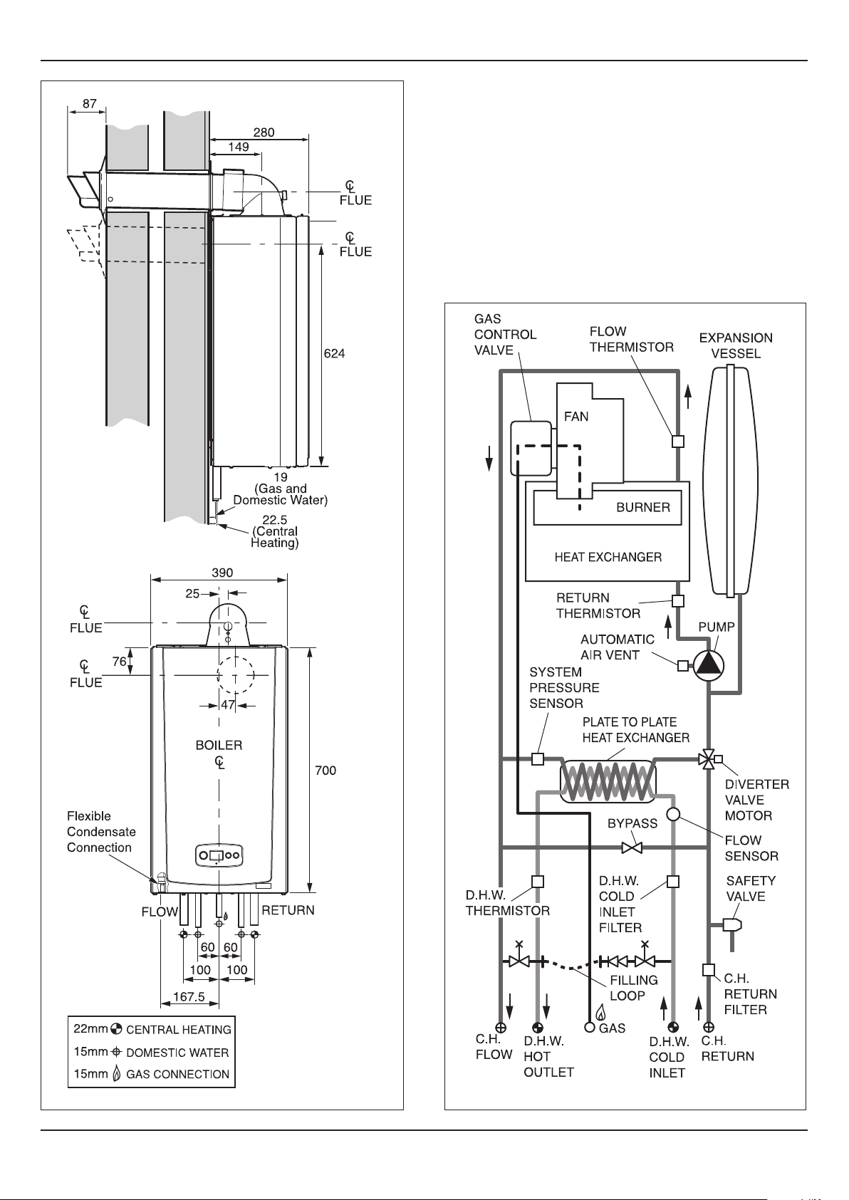
2 Boiler Dimensions and Hydraulic
Schematic
All dimensions are given in millimetres (except as noted).
The general arrangment of the boiler is shown in diagram 2.1
and the hydraulic and gas schematic, diagram 2.2.
The data label is positioned on the front of the inner casing
panel.
13089
- 8 -
Diagram 2.2Diagram 2.1
0020107232_03 - 12/14 - Glow-worm

INSTALLATION
3 Boiler Location, Clearances and
Ventilation
3.1 Location
This boiler is not suitable for outdoor installation.
This boiler may be installed in any room, although particular
attention is drawn to the installation of a boiler in a room
containing a bath or shower where reference must be made to
the relevant requirements.
This boiler is suitable for installation in bathroom zones 2 and 3.
In GB this is the current I.E.E. WIRING REGULATIONS and
BUILDING REGULATIONS.
In IE reference should be made to the current edition of I.S.813
“Domestic Gas Installations” and the current ETCI rules.
3.2 Clearances
The boiler should be positioned so that at least the minimum
operational and servicing clearances are provided, see diagram
3.1.
Additional clearances may be benecial around the boiler for
installation and servicing.
For ue installations where external access is not practicable,
consideration should be given for the space required to insert
the ue internally, which may necessitate clearance larger than
those specied in diagram 3.1.
13127
3.3 Timber Frame Buildings
If the boiler is to be installed in a timber frame building it should
be tted in accordance with the Institute of Gas Engineers
document IGE/UP/7/1998. If in doubt seek advice from local
gas undertaking or Glow-worm.
3.4 Combustible Material
The boiler and ue are suitable for installation onto and through
combustible materials provided that:-
1) Minimum 5mm clearance is maintained around the
circumference of the ue (air intake).
2) The combustible surface and xings are suitable for
supporting the load.
3) The minimum clearances from the boiler case are
maintained.
3.5 Room Ventilation
The boiler is room sealed so a permanent air vent is not
required.
3.6 Cupboard or Compartment Ventilation
Due to the high efciency and low casing temperature of this
boiler, cupboard or compartment ventilation is not necessary.
• Existing ventilation should be investigated for its purpose
before removing.
Diagram 3.1
3.7 Airing Cupboard Installation
If the boiler is to be installed in an airing cupboard it is not
required to separate the boiler with a non-combustible partition.
However, installation and servicing clearances must be
maintained, and the boiler kept clear of any clothing. Details of
essential features of cupboard/compartment design including
airing cupboard installations are given in BS 6891. In IE the
current edition of IS 813.
3.8 Roof Restricting Installation
It is not necessary to ensure sufcient clearance between
the boiler and combustible materials or components. This is
because the temperature of the boiler will always be less than
o
C due to its nominal heat output.
85
0020107232_03 - 12/14 - Glow-worm
- 9 -

INSTALLATION
4 Evacuation of Combustion Gas
4.1 Regulation
Only ue accessories supplied by Glow-worm
must be used.
Different ue outlet congurations can be carried out.
• Consult your supplier for more information about the other
possibilities and associated accessories.
44 mm/m
• Standard ue terminal kits have an in-built fall back to the
boiler to drain the condensate. These can be tted level
between the appliance and the termination position. All other
extended ues must have a fall of at least 44mm/m
If the ue terminal is positioned near a light
source insects may enter the ue system.
Where safe and practical to do so advise the
homeowner to check the ue outlet and clear
visible insects from the terminal end.
H* and J* See diagram 4.2. These dimensions comply with
the building regulations, but they may need to be increased to
avoid wall staining and nuisance from pluming depending on
site conditions.
Terminal Guard
A terminal guard is required if persons could come into contact
with the terminal or the terminal could be subject to damage.
If a terminal guard is required, it must be positioned to provide
minimum of 50mm clearance from any part of the terminal and
be central over the terminal.
The guard should be similar to that shown in diagram 4.1.
A suitable guard is manufactured by: Tower Flue Components
Morley Rd.
Tonbridge
Kent TN9 1RA.
Size: 280mm x 165mm. Part No: CGDK3
15583
The maximum length of the ue outlet is dened according to its
type (for example C13).
• Whatever the kind of ue system chosen, observe the
minimum distances indicated in the chart below to position
the ue terminals.
• To install the ue, refer to the separate ue instruction
supplied with your appliance.
• Explain these requirements to the user of the appliance.
If necessary, you must install terminal
a
In GB the minimum acceptable siting dimensions for the
terminal from obstructions, other terminals and ventilation
openings are shown in diagram overleaf.
In IE the minimum distances for ue terminal positioning must
be those detailed in I.S.813 “Domestic Gas Installations”.
The terminal must be exposed to the external air, allowing free
passage of air across it at all times.
protection.
Caution! The connection between the ue
elbow and the ue outlet must be sealed.
Diagram 4.1
Being a condensing boiler some pluming may occur from
the ue outlet. This should be taken into consideration when
selecting the position for the terminal.
Carports or similar extensions of a roof only, or a roof and one
wall, require special consideration with respect to any openings,
doors, vents or windows under the roof. Care is required
to protect the roof if made of plastic sheeting. If the carport
comprises of a roof and two or more walls, seek advice from the
local gas supply company before installing the boiler.
- 10 -
0020107232_03 - 12/14 - Glow-worm

INSTALLATION
J
J
U
E
F
A 300mm adjacent to a boundary.
B The dimension below eaves, balconies and car ports
can be reduced to 25mm, as long as the flue terminal
is extended to clear any overhang. External flue
joints must be sealed with a suitable silicon sealant.
C 1500mm between a vertical ue terminal and a
window or dormer window.
D 1200mm between terminals facing each other.
E Vertical ue clearance, 300mm adjacent to a
boundary line.
F 600mm distance to a boundary line, unless it will
cause a nuisance. BS 5440:Part 1 recommends
that care is taken when siting terminal in relation to
boundary lines.
G 300mm minimum clearance from a skylight to a
vertical ue or to another vertical ue.
H Vertical ue clearance, 500mm to non-combustible
building material, and 1500mm clearance to
combustible building material.
J 300mm above, below and either side of an opening
door, air vent or opening window.
K 600mm diagonally to an opening door, air vent or
opening window.
L 300mm to an internal or external corner.
M 2000mm below a Velux window, 600mm above or to
either side of the Velux window.
N 400mm from a pitched roof or 500mm in regions with
heavy snowfall.
P 25mm from vertical drain pipes and soil pipes.
A
G
J
J
H
K
J
Q
G
B
S
D,T
M
V
C
N
R
L
L
P
L
S
S
Q 200mm below eaves and 75mm below gutters, pipe
and drains.
R The dimension below eaves, balconies and car ports
can be reduced to 25mm, as long as the ue terminal
is extended to clear any overhang. External ue
joints must be sealed with suitable silicon sealant.
S 300mm above adjacent ground, balcony or storm
porch.
T 600mm distance to a surface facing a terminal,
unless it will cause a nuisance. BS 5440: Part 1
recommends that care is taken when siting terminals
in relation to surfaces facing a terminal.
U 300mm clearance alongside another terminal.
V 300mm above roof level.
ll measurements are the minimum clearances required.
A
Terminals must be positioned so to avoid combustion products
entering the building.
Support the ue at approximately one metre intervals and at a change
of direction, use suitable brackets and xings.
Installations in car ports are not recommended.
A ue outlet should be protected with a guard if persons could come
into contact with it or if it could be damaged.
The ue cannot be lower than 1 metre from the top of a light well due to
the build up of combustion products.
Dimensions from a ue terminal to a fanned air inlet to be determined
by the ventilation equipment manufacturer.
S
0020107232_03 - 12/14 - Glow-worm
- 11 -
INSTALLATION
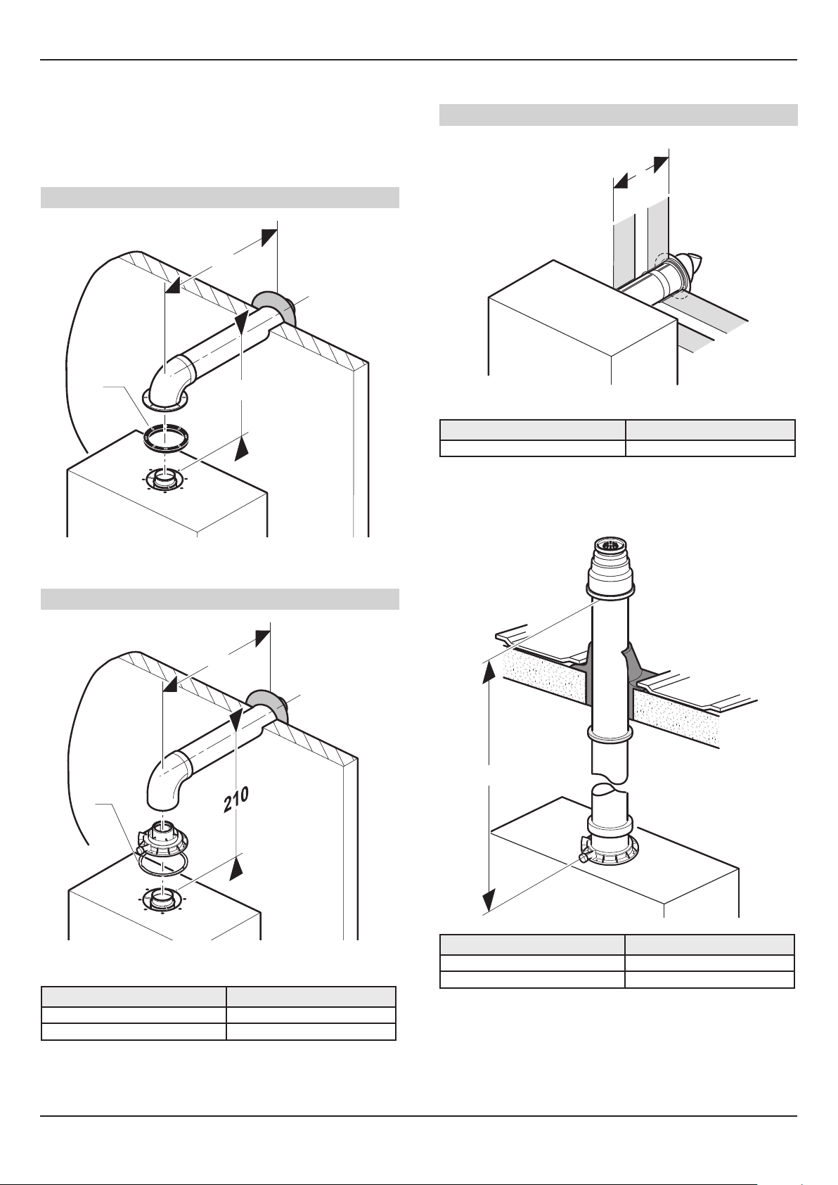
4.2 Flue conguration description
4.2.1 Horizontal concentric ue Ø 60/100 mm
or Ø 80/125 mm (C13 type installation)
Ø 60/100 mm
L
1
63
4.2.2 Telescopic direct rear ue Ø 60/100 mm
Ø 60/100 mm
L
Type Max length
Ø 60/100 512 mm
4.2.3 Vertical concentric ue Ø 60/100 mm
or Ø 80/125 mm (C33 type installation)
Key
1 Gasket (tted)
1
Key
1 Gasket (tted)
Ø 60/100 8 m
Ø 80/125 20 m
Ø 80/125 mm
L
Type Max length
L
Type Max length (L)
Ø 60/100 8 m
Ø 80/125 20 m
Each time an additional 90° bend is necessary (or 2 at 45°), the
length (L) must be reduced by 1 m.
Each time an additional 90° bend is necessary (or 2 at 45°), the
length (L) must be reduced by 1 m.
- 12 -
0020107232_03 - 12/14 - Glow-worm

4.2.4 Multiple boiler chimney ue
L
B
A
1
2
3
4
5
Ø 60/100 mm (C43 type installation)
The ue connecting from the appliance to
the ue system must be supplied from the
manufacturer of the boiler.
C43 ue systems must not be a 'pressurised
system' but act under natural draught principles
C43 type ue systems must have their
own condensate drain tted and not allow
condensate to mix into other appliances
INSTALLATION
Multiple Boiler Chimney Flue Length
The ue length must be calculated and installed according to
the relevant standards EN 13384-1 and 2 (C43 ue systems
only) with reference to the table below and the manufacturers
instructions supplied.
The appliance maximum ue length must be included when
calculating the overall design of the ue system.
NOTE: The horizontal ue terminal must be removed.
Flexicom
24cx
Exhaust mass rate (g/s)
At Min Thermal
Load (40C°/30°C)
At Max Thermal
Load (80C°/60°C)
Exhaust temperature (ºC)
At Min Thermal
Load (40C°/30°C)
At Max Thermal
Load (80C°/60°C)
11.67 14.10 16.39
Key
1 Pressure balancing system
2 Air-inlet pipe
3 Collector pipe
4 Boiler
5 Inspection hatch
A Final storey
B Ground oor
Type Max length (L)
Ø 60/100 8 m
Each time an additional 90° bend is necessary (or 2 at 45°), the
length (L) must be reduced by 1 m.
30cx
Flexicom
Flexicom
35cx
4.30 4.30 4.30
33.2 33.2 36.0
73.3 87.4 86.0
0020107232_03 - 12/14 - Glow-worm
- 13 -
INSTALLATION
5 Water Systems - General
5.1 General
This boiler is designed for use as part of a sealed water central
heating system with fully pumped circulation. The pump,
expansion vessel and associated safety devices are all tted
within the boiler.
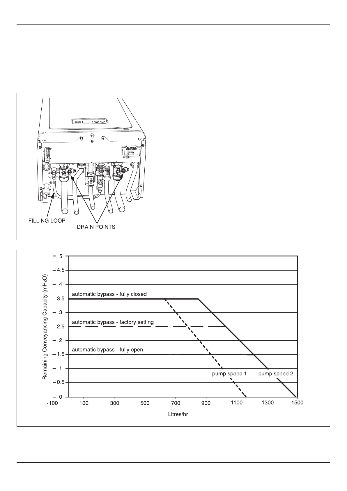
5.2 Draining Points
Draining taps must be provided at all low points of the system,
which will allow the entire system to be drained.
Draining taps shall be to the current issue of BS2879.
Drain points for the appliance are provided at the positions
shown in diagram 5.1.
13925
Diagram 5.1
13102
- 14 -
Diagram 5.2
0020107232_03 - 12/14 - Glow-worm
INSTALLATION
5.3 Water treatment
5.3.1 General
The Glow-worm Flexicom range of boilers have an
Aluminium alloy heat exchanger. Water treatment products
used in the system should be suitable for use with
Aluminium.
Existing system- It is ESSENTIAL that prior to installing
the new boiler the system is thoroughly ushed.
New system- For optimum performance after installation, the
boiler and its associated central heating system should also be
ushed.
For long-term corrosion protection, after ushing, an inhibitor
should be used, refer to the current issue of BS 5449 and BS
7593 on the use of inhibitors in central heating systems.
Debris left in the system can damage the boiler,
reduce efciency and also lead to system
corrosion and generation of ammable gas.
Failure to comply with the guidelines for the
use of water treatment with the appliance will
invalidate the appliance warranty.
The pH value of the system water must be
between 6.5 and 8.5 or the appliance guarantee
will be invalidated.
5.3.3 Inhibiting the system
Add a suitable inhibitor or combined inhibitor/anti-freeze, if the
system is exposed to freezing conditions, to the heating system
in accordance with the DWTA code of practice and inhibitor
manufacturer’s guidelines.
Examples of suitable inhibitors are:
Sentinel X100
Fernox protector F1
Articially softened water must not be used to
ll the central heating system.
Sealing agents - The addition of sealing agents
to the system water is not permitted as this can
cause problems with deposits left in the heat
exchanger.
Ensure that the pH of the treated system water is
i
i
conrmed as between 6.5 and 8.5 and free of any
residual deposits from the ushing process.
Ensure the Benchmark Logbook is completed with
information on water treatment products before
handing over to the user.
Before ushing the system
• Ensure that the system and pipe work is in good working
order.
• Where possible keep the existing boiler/circulating pump in
place when ushing the system.
5.3.2 Flushing the system
• Fill the system with cold water and check for leaks.
• Open all drain cocks and drain the system.
• Close drain cocks and add a suitable ushing agent (cleaner)
compatible with Aluminium at the correct strength for the
system conditions in accordance with the manufacturer’s
instructions.
Examples of suitable ushing agents/cleansers are:
Sentinel X300, X400
Fernox F3
• Circulate the ushing agent before the boiler is red up.
• Run the boiler/system at normal operating temperature as
directed by the manufacturer of the ushing agent.
• It is essential to drain and thoroughly ush the whole system
to remove the ushing agent and debris.
• It may be necessary to use a power ushing machine to aid
the cleansing procedure in some circumstances.
• Close the drain cocks and rell with fresh water and a
suitable inhibitor
• Vent any air from the boiler and system.
0020107232_03 - 12/14 - Glow-worm
- 15 -

INSTALLATION
5 Water systems - Domestic Hot Water
5.4 General
All domestic hot water circuits, connections, ttings must be
in accordance with the relevant standards and water supply
regulations.
For GB: Guidance G17 to G24 and recommendation R17 to
R24 of the Water Regulations Guide (for Scotland, the Water
Byelaws 2000, Scotland).
For IE: The current edition of I.S.813 “Domestic Gas
Installations”.
5.5 Water Pressure
The minimum working pressure to obtain the maximum
domestic ow is:-
24cx 1.0bar
30cx 1.0bar
35cx 1.0bar
The maximum working pressure of the domestic hot water
circuit is 10 bar. If the cold water supply pressure exceeds this,
then a pressure-reducing valve must be tted in the supply to
the boiler.
5.6 ‘Hard’ Water Areas
The temperatures within the heat exchanger are limited by the
boiler control system to minimise scale formation within the hot
water pipework. However, in areas where the water is ‘hard’ (i.e.
more than 200mg/litre), it is recommended that the hot water
setting is reduced and that a scale reducer is tted, refer to the
manufacturer’s instructions or consult the local water company
for additional advice.
5 Water Systems - Sealed Central Heating
system
5.8 Flow Rate
If it is necessary to alter the ow rate, the system can be tted
with a lockable balancing valve in the main ow or return pipes
shown as valve “A” in diagram 5.3. The ow rate through the
boiler must not be allowed to fall below that given in section 1 -
Specication Table.
5.9 Bypass
The boiler is tted with an automatic bypass.
Diagram 5.2 shows the pump head remaining for the heating
system depending on the bypass setting and the speed setting
of the pump, see section 11 Commisioning.
Ensure that under no circumstances does the ow rate drop
below the gure specied, refer to section 1 - Specication
Table and section 11.9.
5.10 Safety Valve
The safety valve is an integral part of the boiler and it cannot
be adjusted. The pipe from the safety discharge valve must
not discharge above an entrance, window or any type of public
access area.
15725
5.7 Domestic Water Flow Rate
The water ow rate is restricted to a maximum 9.4 l/min for
24cx, 11.7 l/min for 30cx and 13.0l/min for 35cx by a restrictor
factory tted within the boiler.
- 16 -
Diagram 5.3
0020107232_03 - 12/14 - Glow-worm
INSTALLATION
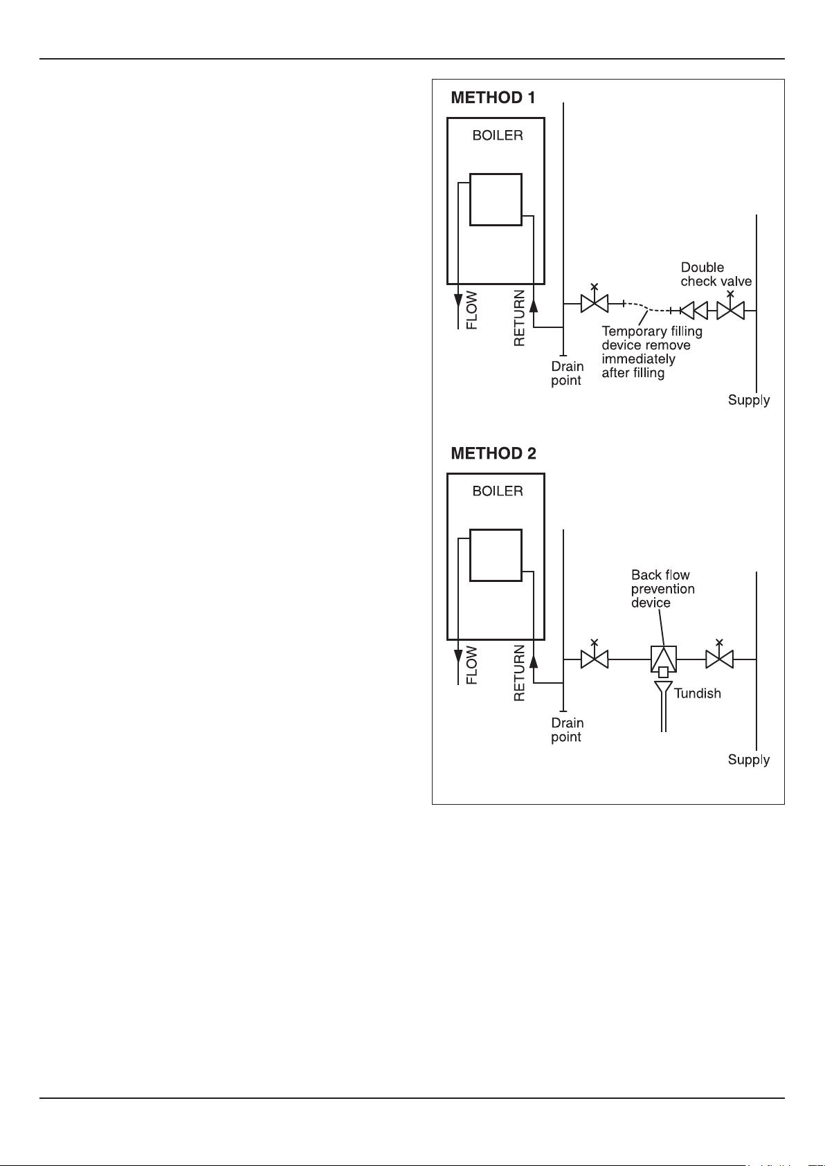
5.11 Filling the Sealed System
The boiler is supplied with a lling device, see diagram 5.1.
This lling device is designed to enable the lling and
pressurisation of the system in the event of loss of pressure.
NOTE: The water pressure at the boiler must be at least
1.2bar to enable lling the boiler to a minimum pressure. If not
pressurisation must be carried out by an alternative lling loop.
Suitable external lling systems are shown diagramatically,
see diagram 5.4. The system should be pressurised to 1bar,
indicated on the digital display with no heating demand.
5.12 Expansion Vessel
The boiler has an integral expansion vessel with a capacity of 8
litres (1.76 gallons), with a charge pressure of 0.5bar.
NOTE: The expansion vessel volume depends on the total
water system volume and the initial system design pressure.
In GB, Guidance on vessel sizing is also given in the current
issue of BS5449 and BS7074 Part 1.
In IE, current edition of I.S.813 “Domestic Gas Installations”.
12253
0020107232_03 - 12/14 - Glow-worm
Diagram 5.4
- 17 -
 Loading...