


Clearly Solar
Installation and Servicing
System Wiring
including
Fluropro
Solar Control
www.glow-worm.co.uk
1

Customer Service:
01773 596510
Technical Helpline:
01773 828300.
General and Sales enquiries:
Tel. 01773 824639
Fax: 01773 820569
To register your Glow-worm appliance call:
0800 0732142
Benchmark places responsibilities on both manufacturers and installers. The purpose is to ensure that customers are provided with the correct equipment for their needs, that it is installed, commissioned and serviced in accordance with the manufacturer’s instructions by competent persons and that it meets the requirements of the appropriate Building Regulations. The Benchmark Checklist can be used to demonstrate compliance with Building Regulations and should be provided to the customer for future reference.
Installers are required to carry out installation, commissioning and servicing work in accordance with the Benchmark Code of Practice which is available from the Heating and Hotwater Industry Council who manage and promote the Scheme.
Visit www.centralheating.co.uk for more information.
2

These instructions consist of, Installation, Commissioning, Service and Fault Finding. The instructions are an integral part of the appliance and must be handed to the user on completion of the installation.
CONTENTS |
|
DESCRIPTION |
SECTION |
PAGE |
|
|
|
|
|
|
|
|
|
|
|
|
Regulations |
|
4 |
|
|
Electrical Supply |
|
4 |
|
|
Testing and Certification |
|
4 |
|
|
CE Mark |
|
4 |
GENERAL |
|
Safety Instructions |
|
4 |
INFORMATION |
|
Intended Use |
|
5 |
|
|
Documents |
|
5 |
|
|
Servicing |
|
5 |
|
|
Cleaning |
|
5 |
|
|
Recycling |
|
5 |
|
|
Specification |
1 |
5 |
|
|
Functions |
2 |
6 |
INSTALLATION |
|
Installation |
3 |
7 |
|
|
Electrical Installation |
4 |
9 |
|
|
Commissioning |
5 |
19 |
|
|
Service / Diagnostics |
6 |
24 |
MAINTENANCE |
|
Sensor Characteristics |
7 |
26 |
|
|
Control - Fault Finding |
8 |
27 |
|
|
|
|
|
3

WARNINGS
SAFETY
The fluropro must be installed by a competent person, who is responsible for adhering to the existing standards and regulations.
ALTERATIONS
Under no circumstances should you ever attempt to make alterations to these components or any other part of the system
SEALED COMPONENTS
Under no circumstances must the user interfere with or adjust sealed parts. IMPORTANT
Danger of death by electric shock! All live parts of the system may be installed, serviced and repaired only by a qualified servicing company!
Risk of overvoltage! Earth the solar circuit as potential equalisation and protection against overvoltage! Attach earthing pipe clips to the solar circuit pipes and connect the clips to a potential rail with a 16mm2 copper cable.
Regulations
When installing and commissioning the system, the current version of regulations below shall be observed.
The electrical installation must be installed by a competent person and in accordance with the relevant standards
CE Mark
The CE mark on the Fluropro solar control indicates that it complies with the basic requirements of the applicable directives as stated on the data badge.
Electrical Supply
The product MUST be earthed.
All system components shall be of an approved type and all wiring to current I.E.E. wiring regulations.
External wiring must be correctly earthed, polarised and in accordance with the relevant standards.
In GB, this is BS 7671.
In IE, this is the current edition of ETCI rules.
The product MUST be connected to a permanent 230V ac, 50Hz supply.
Connection of the whole electrical system of the product, including any heating controls, to the electrical supply MUST be through one common isolator and must be fused 3 Amp maximum.
Isolation should be by a double pole switched fused spur box, with a minimum gap of 3mm for both poles. The fused spur box should be readily accessible and preferably adjacent to the product. It should be identified as to its use.
Alternatively connection can be made through an unswitched shuttered socket and 3A fused 3-pin plug both to the current issue of BS 1363, provided they are not used in a room containing a bath or shower.
Wiring to the product must be PVC 85°C insulated cable, not less than 0.75mm2 (24/0.20mm).
“Benchmark scheme”
Glow-worm support the Benchmark initiative. It is very important that the service record is completed by the installation engineer and handed over to the user.
Safety Instructions
The entire solar system must always be installed and operated in accordance with recognised technical standards. IMPORTANT: Danger of death by electric shock! All live parts of the system may be installed, serviced and repaired only by a qualified servicing company!
IMPORTANT: Risk of overvoltage! Earth the solar circuit as potential equalisation and protection against overvoltage! Attach earthing pipe clips to the solar circuit pipes and connect the clips to a potential rail with a 16mm2 copper cable.
Testing and Certification
This product is tested and certificated for safety and performance. It is, therefore, important that no alteration is made to the product, without permission, in writing, by Glowworm.
Any alteration not approved by Glow-worm, could invalidate the certification, warranty and may also infringe the current issue of the statutory requirements.
4

General Information
Intended use
The Fluropro solar control is a temperature differential controller for solar DHW provision with a cylinder reheat programmer for a supplementary boiler.
The control is suitable for controlling solar systems with a collector array and a storage cylinder.
The Fluropro solar control can be used for controlling a second collector array
If a second collector array is connected, an additional collector sensor (available as an accessory) must be installed. It is possible to determine the solar gain by using an additional gain sensor (supplied with Glow-worm Clearly Solar sets).
The Fluropro solar control is a state-of-the-art control which has been constructed in accordance with recognised safety regulations. Nevertheless, improper use can cause serious or fatal injury to the user or others, and the appliance or other property can be damaged.
The manufacturer or supplier is not liable for any damage resulting from improper use.
The control is not suitable for outdoor use and must be installed in a dry room.
Documents
Please retain these instructions as well as any documents enclosed, for future reference.
We accept no liability in case of damage due to the noncompliance of these instructions.
Servicing
To obtain service, please call your installer or Glow-worm’s own service organisation using the telephone number on the inside front cover of this booklet.
Cleaning
You can clean the housing of the Fluropro solar control with a damp cloth and a little soap.
NOTE: Do not use scouring or cleaning agents which could damage the display.
Recycling
The Fluropro solar control comprises many recyclable parts. The packaging and control shall not be disposed of with domestic waste but according to the current regulations.
1 Specification
14276
5

2 Functions
2.1 Solar gain
The Fluropro solar control works on the principal of differential temperature control. The control always switches on the collector pump when the difference in temperature (collector temperature - cylinder temperature) is greater than the programmed activation difference.
The controller switches off the collector pump when the difference in temperature (collector temperature - cylinder temperature) is less than the programmed deactivation difference.
The installation engineer activates and configures the solar gain function within the Fluropro installer menu.
The solar gain is determined from:
–The difference of temperature between the collector flow and return.
–The flow rate setting of the flow rate adjuster.
–The operating time of the collector pump.
During installation the engineer sets the actual flow rate and enters the setting into the solar control. The solar gain is calculated and displayed by the solar control. The total gain can be called up and reset in the installer menu.
2.2 Solar gain modulation
The rate of solar gain can be modulated to ensure the solar heat at the bottom of the cylinder has sufficient time to dissipate to the top of the cylinder. This maintains demand for solar energy and prevents excessive on and off periods that are inefficient.
The modulation is achieved by means of more frequent on and off operations of the solar pump during solar demand. The pump is switched on and off and the rate depends upon the difference between the collector temperature and lower cylinder sensor. When the activation difference is reached, the function is started (if activated) with an activation duration of 50 % - i.e., the pump is switched on for 30 seconds and then switched off for 30 seconds. If the difference in temperature increases, the activation duration is prolonged (e.g., 45
sec. on, 15 sec. off). When the difference in temperature decreases, the activation duration is reduced (e.g., 20 sec. on, 40 sec. off). The period length is always a minute.
2.3 Cylinder reheat
The cylinder reheat function allows the cylinder to heat up to the required temperature during a set time window, even if the solar gain is insufficient. In this case the water can be reheated using an external boiler or the immersion heater. You can set up times for reheating the solar cylinder, refer to Settings section in Instructions for Use.
2.4 Reheat delay
To prevent unnecessary cylinder reheating by a boiler or an immersion heater, the Fluropro solar control includes a reheat delay function. This function delays the cylinder reheat by up to 30 mins if solar gain is available.
If the solar pump is off and the desired cylinder temperature is not reached after the delay period, the cylinder will be reheated using an external boiler or the immersion heater. The reheat delay function is activated by an engineer within the Fluropro installer menu.
2.5 Legionella protection
The Legionella protection function is designed to kill germs in the cylinder and pipes.
When the function is activated, the cylinder, the hot water pipes, and the circulation pump (if installed), are brought to a temperature of 70°C on the programmed day(s) and at the programmed time
In doing so, the cylinder temperature is raised to 70°C and the corresponding circulation pump is switched on (if installed). First, an attempt will be made using solar gain alone to reach the target temperature over a 90 min. period. If this is not successful, the Legionella protection is carried out using an external boiler or an immersion heater, whichever has been set up for this thermal protection. The Legionella protection function will stop once a temperature of at least 70°C has been maintained for a period of 30 minutes.
The installation engineer activates the Legionella protection function within the Fluropro installer menu and specifies whether the thermal disinfection should take place at 3:30 p.m. or at 4:00 a.m., i.e. offset gain versus cheaper electricity.
2.6 Anti-seize protection for pumps
If no pumping has occurred for 23 hours, all installed pumps are switched on for approx. 3 seconds to prevent pumps from seizing.
2.7 Secondary recirculation
The Fluropro solar control includes a programmer channel for a DHW secondary return. A secondary return should not be used with Glow-worm twin coil unvented solar cylinders.
2.8 Calendar
The controller is equipped with a calendar so that it can automatically adjust the clock by 1hr between GMT and BST. To activate, simply enter the current date within the Fluropro installer menu
NOTE: In the event of a power failure, the controller only has a power reserve of 30 minutes. After 30 minutes, the internal clock stops and the calender will not automatically resume function once power has been restored. In this case the time and date will need to be reset.
6

3 Installation
3.1 Contents of sets
Using Table1, verify the contents of the Fluropro solar control set.
Item |
Quantity |
Components |
1 |
1 |
Fluropro |
2 |
1 |
Collector sensor |
3 |
2 |
Cylinder sensor |
Table 1
The gain sensor is a separate item and is also supplied as part of the Glow-worm Clearly Sets.
3.2 Installing cylinder sensors
The cylinder sensors are designed so that they can be used as immersion sensors or surface sensors.
Install the two sensors in the solar cylinder, see diagram 3.1, and connect to the wiring as shown in wiring diagram. When used as a surface sensor, the sensor is secured to the flow pipe or the return pipe as appropriate using the
supplied tension band, see diagram 3.2. In order to guarantee good heat transfer, the sensor is flat on one side. We also recommend that the pipe with the sensor is insulated, in order to enable the best possible measuring of temperature.
Refer to cylinder instructions for the location of sensors and specific fitting instructions.
3.3 Accessories
If a second collector array is connected, it is necessary to install a second collector sensor from the Glow-worm accessory range.
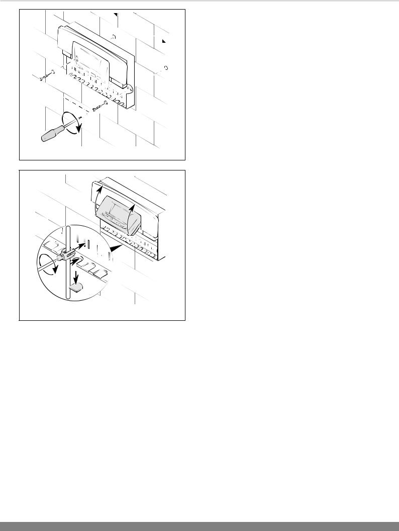
3.4 Installing the Fluropro housing
The Fluropro solar control is designed to be mounted on a wall. The wiring terminals within this control includes the
connectors. These connectors must be used for all wiring to this control.
The cover consists of two parts, which can be removed separately:
•As shown in diagram 3.3, pull the lower front cover off of the controller housing.
•Mark the position of both holes and drill, see diagram 3.4.
•Select wall plugs to suit, and screw the controller housing on tightly.
UPPER |
14361 |
TEMPERATURE |
|
SENSOR |
|
TEMPERATURE |
|
SENSOR |
|
GAIN |
|
|
LOWER |
|
TEMPERATURE |
|
SENSOR |
|
Diagram 3.1 |
|
14261 |
Diagram 3.2
14260
Diagram 3.3
7
3 |
Installation |
230 |
14260 |
|
|
Diagram 3.4 |
|
|
14263 |
Diagram 3.5
•Lift up the control panel, see diagram 3.5.
•Wire the controller according to the selected hydraulic plan
(see Section 4 Electrical installation).
•Secure all cables with the accompanying cable clamps.
•Push the control panel back into place.
•Re-attach the lower front cover.
8

4 Electrical Installation
Electrical Supply
The product MUST be earthed.
All system components shall be of an approved type and all wiring to current I.E.E. wiring regulations.
External wiring must be correctly earthed, polarised and in accordance with the relevant standards.
In GB, this is BS 7671.
In IE, this is the current edition of ETCI rules.
The product MUST be connected to a permanent 230V ac, 50Hz supply.
Connection of the whole electrical system of the product, including any heating controls, to the electrical supply MUST be through one common isolator and must be fused 3 Amp maximum.
Isolation should be by a double pole switched fused spur box, with a minimum gap of 3mm for both poles. The fused spur box should be readily accessible and preferably adjacent to the product. It should be identified as to its use.
Alternatively connection can be made through an unswitched shuttered socket and 3A fused 3-pin plug both to the current issue of BS 1363, provided they are not used in a room containing a bath or shower.
Wiring to the product must be PVC 85°C insulated cable, not less than 0.75mm2 (24/0.20mm).
IMPORTANT: Risk of fatal electric shock from touching live connections.
Before working on the system wiring, including the Fluropro, isolate the power supply.
The circuit board can be damaged if short circuited through the connection leads. For safety purposes, a max. of 30 mm of insulation may be removed from the ends of 230 V leads which will be connected to Fluropro wiring connectors. If more insulation is removed, there is a risk of short circuiting the circuit board.
When exchanging the solar controller in an existing system, sensor-curve characteristics should be taken into consideration and the sensors should be replaced if necessary!
The immersion heater must be installed with an additional relay or contactor with a circuit-breaking capacity of at least 16 A. Never operate an immersion heater in connection with the Fluropro without an additional external relay or contactor.
9
 Loading...