


AGP
AGP 4X ( )AGP 4X(1.5V)
AGP 2X (3.3V) Intel® 845(E/G)/850 (E)
AGP 2X(3.3V) AGP 2X (3.3V)
Diamond Vipper V770
2X/4X Jumper 2X 4X
2X(3.3V) GA-8IR533
Jumper 4X (1.5V)
SiS 305 Power Color ATi Rage
128 Pro 2X/4X
2X(3.3V) GA-8IR533
AG32S(G) ATi
Rage 128 Pro AGP4X

oEN 55011
oEN 55013
oEN 55014
oEN 55015
oEN 55020
T EN 55022
oDIN VDE 0855
opart 10
opart 12
T CE marking
oEN 60065
oEN 60335
Declaration of Conformity
We, Manufacturer/Importer
(full address)
G.B.T. Technology Träding GMbH
Ausschlager Weg 41, 1F, 20537 Hamburg, Germany
declare that the product
( description of the apparatus, system, installation to which it refers)
Mother Board
GA-8IR533
is in conformity with
(reference to the specification under which conformity is declared) in accordance with 89/336 EEC-EMC Directive
Limits and methods of measurement |
o EN 61000-3-2* |
Disturbances in supply systems cause |
|
of radio disturbance characteristics of |
T EN 60555-2 |
by household appliances and similar |
|
industrial,scientific and medical (ISM |
|
electrical equipment “Harmonics” |
|
high frequency equipment |
|
|
|
Limits and methods of measurement |
o EN 61000-3-3* |
Disturbances in supply systems cause |
|
of radio disturbance characteristics of |
T EN 60555-3 |
by household appliances and similar |
|
broadcast receivers and associated |
electrical equipment “Voltage fluctuations” |
||
|
|||
equipment |
|
|
Limits and methods of measurement of radio disturbance characteristics of household electrical appliances, portable tools and similar electrical apparatus
Limits and methods of measurement of radio disturbance characteristics of fluorescent lamps and luminaries
TEN 50081-1
TEN 50082-1
o EN 55081-2
Generic emission standard Part 1: Residual commercial and light industry
Generic immunity standard Part 1: Residual commercial and light industry
Generic emission standard Part 2: Industrial environment
Immunity from radio interference of |
o EN 55082-2 |
Generic emission standard Part 2: |
broadcast receivers and associated |
|
Industrial environment |
equipment |
|
|
Limits and methods of measurement |
o ENV 55104 |
lmmunity requirements for household |
of radio disturbance characteristics of |
|
appliances tools and similar apparatus |
information technology equipment |
|
|
Cabled distribution systems; Equipment |
o EN50091-2 |
EMC requirements for uninterruptible |
for receiving and/or distribution from |
|
power systems (UPS) |
sound and television signals |
|
|
|
(EC conformity marking) |
|
The manufacturer also declares the conformity of above mentioned product |
|
|
with the actual required safety standards in accordance with LVD 73/23 EEC |
|
|
Safety requirements for mains operated |
o EN 60950 |
|
electronic and related apparatus for |
|
|
household and similar general use |
|
|
Safety of household and similar |
o EN 50091-1 |
|
electrical appliances |
|
|
|
Manufacturer/Importer |
|
|
Signature: |
|
(Stamp) |
Date : May. 17, 2002 |
Name: |
|
|
|
Timmy Huang
Timmy Huang

DECLARATION OF CONFORMITY
Per FCC Part 2 Section 2.1077(a)
Responsible Party Name:G.B.T. INC. (U.S.A.)
Address: 17358 Railroad Street
City of Industry, CA 91748
Phone/Fax No: (818) 854-9338/ (818) 854-9339
hereby declares that the product
Product Name: Motherboard
Model Number:GA-8IR533
Conforms to the following specifications:
FCC Part 15, Subpart B, Section 15.107(a) and Section 15.109 (a),Class B Digital Device
Supplementary Information:
This device complies with part 15 of the FCC Rules. Operation is subject to the following two conditions: (1) This device may not cause harmful and (2) this device must accept any inference received, including that may cause undesired operation.
Representative Person’s Name: ERIC LU
Signature: Eric Lu
Date: May. 17,2002
GA-8IR533
P4 DDR
Pentium® 4 Rev . 1004
12MC-8IR533-1004

GA-8IR533 |
|
|
|
.................................................................................. |
4 |
.................................................................................. |
4 |
............................................................................ |
5 |
................................................................................................................ |
5 |
GA-8IR533 Layout .................................................................. |
7 |
........................................................ |
8 |
1: (CPU) ..................................................................... |
9 |
............................................................................................. |
9 |
........................................................................... |
10 |
2: .............................................................................. |
11 |
3: ......................................................................................... |
13 |
4: 14 |
|
4-1 I/O .................................................................... |
14 |
4-2 .............................................................................. |
16 |
4-3 .......................................................................................... |
22 |
BIOS ...................................................... |
23 |
(BIOS F1) ........................................................... |
24 |
CMOS ............................................................................................... |
26 |
BIOS ....................................................................................... |
29 |
................................................................................................... |
31 |
2

|
|
................................................................................................... |
36 |
PCI .......................................................................... |
39 |
................................................................................................... |
40 |
/ ................................................................................................ |
41 |
.............................................................................................................. |
43 |
Fail-Safe ...................................................................................... |
44 |
Optimized .................................................................................... |
45 |
(Supervisor)/ (User) ......................................... |
46 |
SET UP ................................................................... |
47 |
SET UP .............................................................. |
48 |
............................................ |
49 |
........................................................................................ |
49 |
Q-Flash .............................................................................................. |
50 |
Easy T uneTM 4 ............................................................................................. |
52 |
@ BIOSTM ..................................................................................................... |
53 |
.......................................................................... |
54 |
3

GA-8IR533
þGA-8IR533
þx 1 / x 1
þ(IUCD)
þGA-8IR533
þ2 x 1
3.(CPU RAM)
5.ATX
PCB
4

|
— |
ATX 19.6 x 29.5 |
||
|
— |
GA-8IR533 |
|
|
|
|
GA-8IR GA-8I R533 |
||
|
|
|
||
|
— |
Socket 478 Intel Micro FC -PGA2 Pentium® 4 |
|
|
|
— |
Intel® Pentium® 4 (Northwood, 0.13 m) |
||
|
— |
Intel® Pentium® 4 400M Hz FSB |
||
|
— |
Pentium® 4 |
||
|
— |
2nd CPU |
||
|
|
|
||
|
— |
Chipset Intel® 845D HOST/AGP/Controller |
|
|
|
— |
ICH2 I/O Controller Hub |
||
|
|
|
|
|
|
— |
3 |
184-pin DDR DIMM |
|
|
— |
PC1600/PC2100 DDR DIMM |
||
|
— |
2.5V DDR DIMM |
||
|
— 64bit ECC type DRAM integrity mode |
|||
|
— |
2GB |
||
|
|
|
||
I/O |
— |
ITE8702 |
|
|
|
|
|
||
|
— |
1 AGP 4X (1.5V) |
|
|
|
— 5 PCI 33MHz PCI2.2 compliant |
|||
|
|
|
||
IDE |
— |
2 IDE bus master (UDMA 33/ATA 66/ATA 100) IDE |
|
|
|
|
4 ATAPI |
||
|
— |
PIO mode 3,4 (U DMA33/ATA 66/ATA100 IDE) ATAPI CD- |
||
|
|
ROM |
||
|
|
|
|
|
|
— |
1 |
(360K, 720K, 1.2M, 1.44M |
|
|
|
2.88M bytes) |
||
|
— |
1 |
Normal/E PP/ECP |
|
|
— |
2 |
(COM A & CO M B) |
|
|
— |
4 |
USB ( x 2, x 2) |
|
|
— |
1 |
|
|
|
|
|
|
|
.......
5

GA-8IR533
|
— |
RealTek ALC650 CODEC |
|
— |
Line Out : 2 |
|
— |
Line I n : 2 ( ) |
|
— |
Mic I n : / ( ) |
|
— |
SPDIF out : |
|
— CD In / AUX In / Game Port |
|
|
|
|
PS/2 |
— |
PS/2 PS/2 |
|
|
|
BIOS |
— |
AWARD BIOS, 2M bit |
|
— |
Q-Flash |
|
|
|
|
— |
PS/2 |
|
— |
PS/2 |
|
— STR (Suspend-To-RAM) |
|
|
— |
AC Recovery |
|
— |
USB / wake up from S3 |
|
— |
@BIOS™ |
|
— |
EasyTune 4™ |
CPU CPU
CPU
6

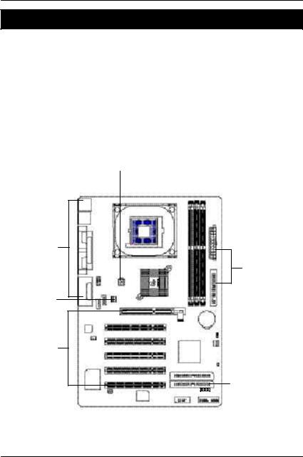
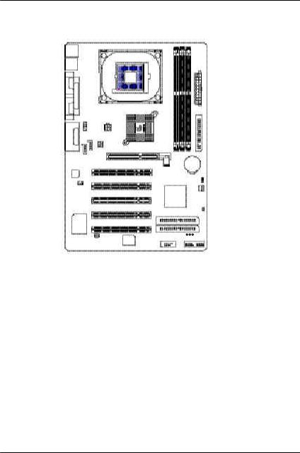
GA-8IR533 Layout
KB_MS |
|
|
|
USB |
|
|
|
COMA |
|
|
|
|
LPT |
|
|
COMB |
|
|
|
|
F_AUDIO |
ATX_12V |
|
IN LINE OUT LINE IN |
GAME |
|
CPU_FAN |
_ |
|
|
|
MIC |
|
|
|
|
AUX IN |
CD IN |
|
CODEC
SUR_CEN
SOCKET478
845D
P4 Tit an533
ITE8702
SPDIF |
BIOS |
AGP
PCI1
PCI2
PCI3
PCI4
PCI5
ATX
GA-8IR533 |
|
FDD |
DDR1 |
DDR2 |
DDR3 |
|
|
BATTERY |
|
|
CLR_CMOS |
|
|
SYS _FAN |
ICH2 |
|
|
|
|
CI |
|
|
IDE2 |
|
|
IDE1 |
PWR_LED  F_USB1 F_PANEL
7
GA-8IR533
1 - (CPU)
2 -
3 -
4 -
5 - BIOS
6 -
4 |
1 |
2 |
||||
|
|
|
|
|
|
|
|
|
|
|
|
|
|
|
|
|
|
|
|
|
4
4
1
3
 4
4
8
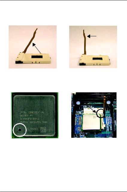
1: (CPU)
65
1. |
2. |
65 , , |
90 |
90 , |
|
” ” |
|
|
|
1 |
|
1 |
|
3. |
|
4. ( |
|
),
MCPU , ,
9
GA-8IR533
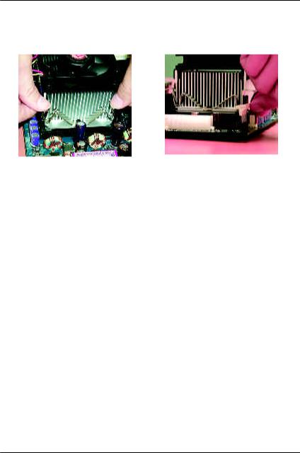
1. CPU |
2. CPU |
|
”C PU |
|
” |
|
|
|
|
MIntel
MCPU
( CPUCPUCPU
)
M,
MCPU CPU FAN
( )
10

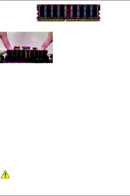
2:
3 184Pin(DIMM) BIOS
DIMM
NEC, Toshiba, PQI, Winbond
Unbuffered DDR DIMM
Devices used on DIMM |
1 DIMM x 64 / x 72 |
2 DIMMs x 64 / x 72 |
3 DIMMs x 64 / x 72 |
||||
|
|
|
|
||||
64 Mbit (2Mx8x4 banks) |
128 MBytes |
256 MBytes |
768 MBytes |
||||
|
|
|
|
||||
64 Mbit (1Mx16x4 banks) |
32 MBytes |
64 MBytes |
96 MBytes |
||||
|
|
|
|
||||
128 Mbit(4Mx8x4 banks) |
256 MBytes |
512 MBytes |
768 MBytes |
||||
|
|
|
|
||||
128 Mbit(2Mx16x4 banks) |
64 MBytes |
128 MBytes |
192 MBytes |
||||
|
|
|
|
||||
256 Mbit(8Mx8x4 banks) |
512 MBytes |
1 GBytes |
1.5 GBytes |
||||
|
|
|
|
||||
256 Mbit(4Mx16x4 banks) |
128 MBytes |
256 MBytes |
384 MBytes |
||||
|
|
|
|
||||
512 Mbit(16Mx8x4 banks) |
1 GBytes |
2 GBytes |
3 GBytes |
||||
|
|
|
|
||||
512 Mbit(8Mx16x4 banks) |
256 MBytes |
512 MBytes |
768 MBytes |
||||
Intel 845E/G x 16 DDR |
|
||||||
|
|
|
|
|
|
|
|
DDR1 |
DDR2 |
|
DDR3 |
|
|
|
|
|
|
|
|
|
|
|
|
S |
S |
|
S |
|
|
|
|
|
|
|
|
|
|
|
|
D |
S |
|
S |
|
|
|
|
|
|
|
|
|
|
|
|
D |
D |
|
X |
|
|
|
|
|
|
|
|
|
|
|
|
D |
X |
|
D |
|
|
|
|
|
|
|
|
|
|
|
|
S |
D |
|
X |
|
|
|
|
|
|
|
|
|
|
|
|
S |
X |
|
D |
|
|
|
|
D: Double Sided DIMM S: Single Sided DIMM
X: Not Use
11
GA-8IR533
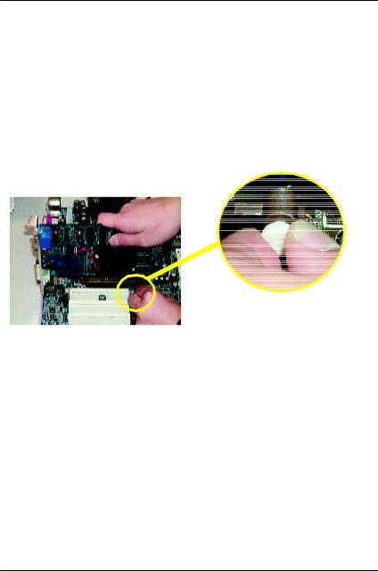
DDR
1.,
組插入定位後,
3. DIMM
DDR
DDR(Double Data Rate) PC SDRAM
SDRA M
DDR OEM
DDR SDRAM
SDRAM DDR SDRAM
DDR 2.1G B/s DDR
DRAM
PC SDRAM 3. 3 volts
DDR 2.5 v olts DDR
MSTR/DIMM DIMM
12
3:
2.()
7.BIOS
|
/ AGP |
|
AGP |
A GP |
|
A G P |
||
|
||
|
AGP |
13
GA-8IR533
4:
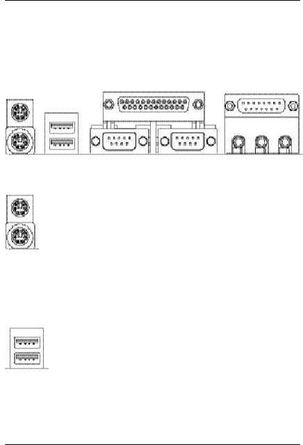
4-1 I/O
w x
u
v
y
u PS /2 PS /2 |
Ø P S/ 2 |
PS/2 |
PS/2 |
|
|
(6 pin Female) |
|
PS/2 |
|
(6 pin Female) |
|
v |
Ø |
||
|
|
|
|
|
|
|
|
|
|
|
USB USB |
|
|
USB 0 |
USB U S B ZI P U S B |
|
|
|
|
|
|
||
|
|
|
|
|
|
USB 1 |
|
|
|
||
|
|
|
|
|
|
|
USB |
|
|
|
|
14
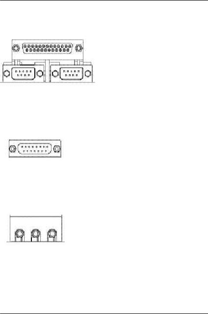
w A/ B/
(25 pin Female)
A B
(9 pin Male)
機,串列埠
x
Ø
(15 pin Female)
y
Ø
|
|
|
|
Line Out |
MIC In |
||
|
|
|
|
Line In
15
GA-8IR533
4-2
P |
|
|
|
|
|
|
|
|
|
|
|
|
|
|
|
|
|
|
|
|
|
A |
|
|
|
|
|
|
|
|
|
|
|
|
|
|
|
|
|||||||
|
|
|
|
|
|
|
|
|
|
|
|
|
|
|
|
|||||||
O |
|
|
|
|
|
|
|
|
|
|
|
|
|
|
|
|
B |
|||||
N |
|
|
|
|
|
|
|
|
|
|
|
|
|
|
|
|
|
|
|
|
||
M |
|
|
|
|
|
|
|
|
|
|
|
|
|
|
|
|
|
|
|
|
||
|
|
|
|
|
|
|
|
|
|
|
|
|
|
|
|
|
||||||
L |
|
|
|
|
|
|
|
|
|
|
|
|
|
|
|
|
|
|
|
|
|
C |
|
|
|
|
|
|
|
|
|
|
|
|
|
|
|
|
|||||||
K |
|
|
|
|
|
|
|
|
|
|
|
|
|
|
|
|
|
|
|
|
|
|
|
|
|
|
|
|
|
|
|
|
|
|
|
|
|
|
|
|
|
|
|||
|
|
|
|
|
|
|
|
|
|
|
|
|
|
|
|
|
|
|
|
|
D |
|
|
|
|
|
|
|
|
|
|
|
|
|
|
|
|
||||||||
|
|
|
|
|
|
|
|
|
|
|
|
|
|
|
|
|
|
|
|
|
|
|
|
|
|
|
|
|
|
|
|
|
|
|
|
|
|
|
|
|
|
|
|
||
|
|
|
|
|
|
|
|
|
|
|
|
|
|
|
|
|
|
|
|
|
|
E |
|
|
|
|
|
|
|
|
|
|
|
|
|
|
|
|
|
|
|
|
|
||
|
|
|
|
|
|
|
|
|
|
|
|
|
|
|
|
|
|
|
|
|
|
F |
|
|
|
|
|
|
|
|
|
|
|
|
|
|
|
|
|
|
|
|
|
||
|
|
|
|
|
J |
|
|
|
|
|
|
|
|
|
|
|
|
|
|
|
|
G |
|
|
|
|
|
|
|
|
|
|
|
|
|
|
|
|
|
|
|||||
|
|
|
|
|
|
|
|
|
|
|
|
|
|
|
|
|
|
|
||||
|
|
|
|
|
|
I |
|
|
|
|
|
H |
||||||||||
|
|
|
|
|
|
|
|
|
|
|
|
|
|
|
|
|
|
|
|
|
|
|
A) ATX |
|
I) |
F_USB1 |
|||||||||||||||||||
|
|
|
|
|
|
|
|
|
|
|
|
|
|
|
|
|
|
|
|
|
|
|
B) FDD |
|
J) |
SPDIF |
|||||||||||||||||||
|
|
|
|
|
|
|
|
|
|
|
|
|
|
|
|
|
|
|
|
|
|
|
C) BATTERY |
|
K) |
SUR_CEN |
|||||||||||||||||||
|
|
|
|
|
|
|
|
|
|
|
|
|
|
|
|
|
|
|
|
|
|
|
D) SYS_FAN |
|
L) |
AUX_IN |
|||||||||||||||||||
|
|
|
|
|
|
|
|
|
|
|
|
|
|
|
|
|
|
|
|
|
|
|
E) CI |
|
M) CD_IN |
||||||||||||||||||||
|
|
|
|
|
|
|
|
|
|
|
|
|
|
|
|
|
|
|
|
|
|
|
F) IDE1/IDE2 |
|
N) |
CPU_FAN |
|||||||||||||||||||
|
|
|
|
|
|
|
|
|
|
|
|
|
|
|
|
|
|
|
|
|
|
|
G) PWR_LED |
|
O) |
F_AUDIO |
|||||||||||||||||||
|
|
|
|
|
|
|
|
|
|
|
|
|
|
|
|
|
|
|
|
|
|
|
H) F_PANEL |
|
P) |
ATX_12V |
|||||||||||||||||||
|
|
|
|
|
|
|
|
|
|
|
|
|
|
|
|
|
|
|
|
|
|
|
16
|
|
|
|
|
|
|
|
|
|
P) ATX12V ( +12V ) |
|
||||||||
3 |
4 |
|
|
Ø ATX + 12V |
|||||
+12V |
|
|
|
|
|
|
+12V |
CPU |
|
|
|
|
|
|
|
||||
|
|
|
|
|
|
|
|
ATX+ 12V , |
|
|
|
|
2 |
||||||
1 |
|
|
|
||||||
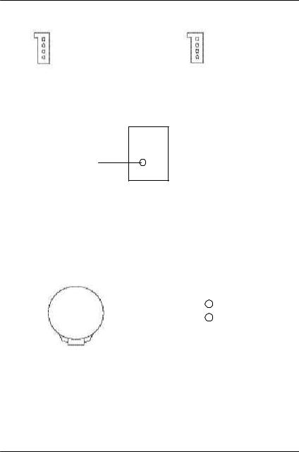
N ) CPU_FAN (CPU ) |
|||||||||
|
|
|
|
|
|
|
|
|
Ø |
|
|
|
|
|
|
|
|
||
|
|
|
|
|
|
|
|||
|
|
|
|
|
|
|
|
+12V/Control |
|
|
|
|
|
|
|
|
|
||
|
|
|
|
|
|
|
|
||
1 |
|
|
|
|
|||||
|
|
|
|
|
|
|
|||
|
|
|
|
|
|
|
CPU |
||
|
|
|
|
|
|
|
|
|
|
|
|
|
|
|
|
|
|
|
600 |
D) SYS_FAN |
|
|
|
|
|
B ) F DD ( ) |
|||
( ) |
|
||||||||
1 |
|
|
|
+12V/Control |
|
|
|
||
|
|
|
|
|
|
|
|||
|
|
|
|
|
|
|
|||
1
F) IDE1/ IDE2 ( IDE )
FDD
IDE |
1 |
Ø :
I DE
IDE
IDE
17
GA-8IR533
M) CD_IN ( ) |
L) AUX_IN ( ) |
||||||||||||
1 |
|
|
|
|
|
1 |
|
|
|
|
|
||
|
|
|
|
|
|
|
|
|
|
||||
|
|
|
|
|
|
|
|
|
|
|
|
|
|
|
|
|
|
|
|
|
|
|
|
|
|
||
|
|
|
|
|
|
|
|
|
|
||||
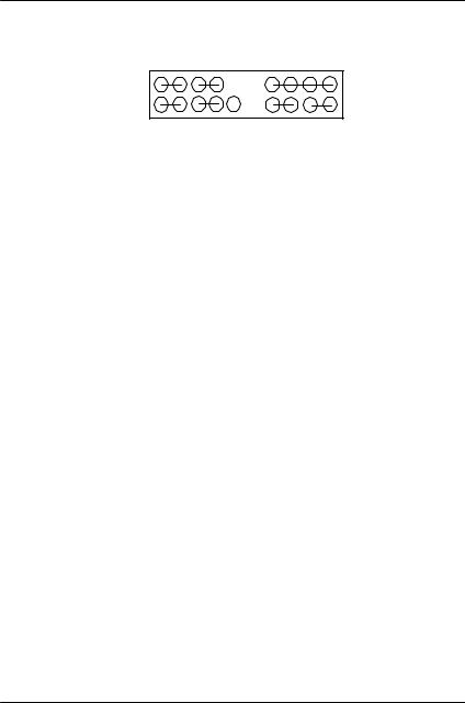
O) F_AU DIO ( )
1 2
MIC 

REF 

Front Audio (R)
 Rear Audio (R)
Reserved
Front Audio (L)
 Rear Audio (L)
910
銷商詢問相關問題。注意:若您要使用第二組音源接腳,請移除Pin5-6 Pin9-10
Jumper
C) BATTERY ( ) |
E) C I ( ) |
||||
+ |
|
|
|
|
|
|
|
|
|
||
|
|
|
|
||
1 |
|
|
|
|
|
|
|
||||
|
|
|
|
|
|
Ø
v
v
v
18
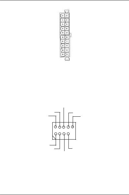
A ) ATX ( ATX Power)
|
|
|
|
+12V |
20 |
|
|
|
|
|
|
||||
5V SB (Stand by +5V) |
|
|
|
|
|
|
VCC |
||||||||
|
|
|
|
|
|
||||||||||
|
|
|
|
|
|
|
|
|
|
|
VCC |
||||
|
|
|
|
|
|
|
|
|
|
|
|||||
Power Good |
|
|
|
|
|
|
|
-5V |
|||||||
|
|
|
|
|
|||||||||||
|
|
|
|
|
|
|
|
|
|
|
|
||||
|
|
|
|
|
|
|
|
||||||||
|
|
|
|
VCC |
|
|
|
|
|
|
GND |
||||
|
|
|
|
||||||||||||
|
|
|
|
|
|
|
|
|
|
|
|||||
|
|
|
|
|
|
|
|
||||||||
|
|
|
|
VCC |
|
|
|
|
|
|
PS-ON(Soft On/Off) |
||||
|
|
|
|
|
|||||||||||
|
|
|
|
|
|
|
|
|
|
|
|
|
|||
|
|
|
|
|
|
|
|
|
|
||||||
|
|
|
|
3.3V |
|
|
|
|
|
|
-12V |
||||
|
|
|
|
|
|||||||||||
3.3V |
|
|
|
|
|
|
|
|
|
|
3.3V |
||||
|
1 |
|
|
|
|
|
|
|
|
||||||
|
|
|
|
|
|
|
|
|
|
|
|
|
|
|
|
ØAC (110/220V) ATXATX AC (110/220V)
I) F_U SB1 ( )(F_U SB1 USB 1.1 )
|
USB Dy+ |
USB Dy - |
|
|
USB Over Current |
1 |
|
|
|
USB Dx - |
|
|
USB Dx+ |
ØUS B US BUSB
19
GA-8IR533 |
|
|
|
|
|
|
|
|
|
H) F _PANEL ( ) |
|
|
|
|
|
||||
|
MPD+ MPD - |
PW+ |
PW- |
|
SPK+ |
|
|
SPK- |
|
2 |
1 |
|
1 |
|
|
1 |
|
|
20 |
|
|
|
|
|
|
|
|
||
1 |
1 |
|
|
1 |
|
1 |
|
1 |
19 |
|
|
|
|
|
|
||||
|
HD+ |
HD- |
RST- |
RST+ |
NC |
GD+ |
GD- |
GN+ |
GN- |
GN (Green Switch) |
Open: Normal Operation |
|
Close: Entering Green Mode |
|
|
GD (Green LED) |
Pin 1: LED anode(+) |
|
Pin 2: LED cathode(-) |
|
M |
|
|
HD (IDE Hard Disk Active LED) |
Pin 1: LED anode(+) |
|
Pin 2: LED cathode(-) |
|
M |
|
|
SPK (Speaker Connector) |
Pin 1: VCC(+) +5v |
|
Pin 2- Pin 3: NC |
|
Pin 4: Data(-) |
|
|
RST (Reset Switch) |
Open: Normal Operation |
|
Close: Reset Hardware System |
|
|
|
M |
|
|
PW (Soft Power Connector) |
Open: Normal Operation : |
|
Close: Power On/Off : / |
|
M |
|
|
MPD (Message LED/Power/ |
Pin 1: LED anode(+) |
Sleep LED) |
Pin 2: LED cathode(-) |
|
M |
|
|
20
 Loading...