


The author assumes no responsibility for any errors or omissions that may appear in this document nor does the author make a commitment to up
date the information contained herein.
Third-party brands and names are the property of their respective owners.
Please do not remove any labels on motherboard, this may void the warranty of this motherboard.
Due to rapid change in technology, some of the specifications might be out of date before pwblicution of this booklet.

GA-6IWF Series
Socket 370 Processor Motherboard
USER’S MANUAL
Socket 370 Processor Motherboard
Rev. 1.0 First Edition
12ME-6IWF-1001

GA-6IWF Series Motherboard |
|
Table of Content |
|
Revision History ..................................................................................... |
6 |
Item Checklist ......................................................................................... |
6 |
WARNING! ............................................................................................... |
7 |
Chapter 1 Introduction ............................................................................. |
8 |
Summary of Features .................................................................................. |
8 |
GA-6IWF Series Motherboard Layout ...................................................... |
10 |
Chapter 2 Hardware Installation Process .............................................. |
11 |
Step 1: Install the Central Processing Unit (CPU)..................................... |
12 |
Step1-1: CPU Installation ................................................................................................ |
12 |
Step1-2:CPU Heat Sink Installation ................................................................................. |
13 |
Step 2: Install memory modules ................................................................ |
14 |
Step 3: Install expension cards ................................................................. |
15 |
Step 4: Connect ribbon cables, cabinet wires, and power supply ........... |
16 |
Step4-1:I/O Back Panel Introduction ................................................................................ |
16 |
Step4-2: Connectors Introduction ..................................................................................... |
18 |
4

|
Table of Content |
Chapter 3 BIOS Setup .......................................................................... |
23 |
The Main Menu (For example: BIOS Ver. :F2) ......................................... |
24 |
Standard CMOS Features ......................................................................... |
26 |
BIOS Features Setup ................................................................................. |
29 |
Chipset Features Setup ............................................................................. |
32 |
Integrated Peripherals .............................................................................. |
34 |
Power Management Setup ....................................................................... |
41 |
PNP/PCI Configuration .............................................................................. |
45 |
PC Health Status ........................................................................................ |
47 |
Frequency/Voltage Control ........................................................................ |
49 |
Load Fail-Safe Defaults ............................................................................. |
50 |
Load Optimized Defaults ........................................................................... |
51 |
Set Supervisor/User Password .................................................................. |
52 |
Save & Exit Setup ....................................................................................... |
53 |
Exit Without Saving ................................................................................... |
54 |
Chapter 4 Technical Reference ............................................................ |
55 |
Block Diagram ........................................................................................... |
55 |
@ BIOS Introduction .................................................................................. |
56 |
Easy TuneIIITM Introduction ....................................................................... |
57 |
Chapter 5 Appendix .............................................................................. |
58 |
5

GA-6IWF Series Motherboard
Revision History
Revision |
Revision Note |
Date |
|
|
|
1.0 |
Initial release of the GA-6IWF Series motherboard user's manual. |
Oct .2001 |
|
|
|
Item Checklist
The GA-6IWF Series motherboard
IDE cable x 1/ Floppy cable x 1
CD for motherboard driver & utility (IUCD)
GA-6IWF Series user’s manual
I/O Shield
6

WARNING!
WARNING!
Computer motherboards and expansion cards contain very delicate Integrated Circuit (IC) chips. To protect them against damage from static electricity, you should follow some precautions whenever you work on your computer.
1.Unplug your computer when working on the inside.
2.Use a grounded wrist strap before handling computer components. If you do not have one, touch both of your hands to a safely grounded object or to a metal object, such as the power supply case.
3.Hold components by the edges and try not touch the IC chips, leads or connectors, or othercomponents.
4.Place components on a grounded antistatic pad or on the bag that came with the components whenever the components are separated from the system.
5.Ensure that the ATX power supply is switched off before you plug in or remove the ATX power connector on the motherboard.
Installing the motherboard to the chassis…
If the motherboard has mounting holes, but they don’t line up with the holes on the base and there are no slots to attach the spacers, do not become alarmed you can still attach the spacers to the mounting holes. Just cut the bottom portion of the spacers (the spacer may be a little hard to cut off, so be careful of your hands). In this way you can still attach the motherboard to the base without worrying about short circuits. Sometimes you may need to use the plastic springs to isolate the screw from the motherboard PCB surface, because the circuit wire may be near by the hole. Be careful, don’t let the screw contact any printed circuit write or parts on the PCB that are near the fixing hole, otherwise it may damage the board or cause board malfunctioning.
7

GA-6IWF Series Motherboard
Chapter 1 |
Introduction |
|
Summary of Features |
||
Form Factor |
|
19.1cm x 23.0cm Flex ATX size form factor, 4 layers PCB. |
|
|
|
Motherboard |
|
GA-6IWF Series Motherboard |
|
|
GA-6IWFE and GA-6IWFL |
|
|
|
CPU |
|
Socket 370 processor |
|
|
supports all new Pentium®III processors (FC-PGA & FC-PGA2 |
|
|
package) |
|
|
supports Celeron processors in FC-PGA & FC-PGA2 package |
|
|
supports 66/100/133MHz system bus frequency |
|
2nd cache depend on CPU |
|
|
|
|
Chipset |
|
Intel 82810E HOST/AGP/SDRAM Controller |
|
|
FW82801BA (ICH2) |
|
|
|
Memory |
|
2 168-pin DIMM sockets |
|
Supports PC-100 SDRAM |
|
|
Supports only 3.3V SDRAM DIMM |
|
|
Supports up to 512MB SDRAM (Max) |
|
|
|
|
I/O Control |
|
W83627HF |
|
|
|
Slots |
|
1 CNR(Communication and Networking Riser) Slot |
|
3 PCI slot supports 33MHz & PCI 2.2 compliant |
|
|
|
|
On-Board IDE |
|
2 IDE bus master (DMA33/ATA66/ATA100) IDE ports for up to 4 |
|
|
ATAPI devices |
|
Supports PIO mode3,4 (UDMA 33/ATA66/ATA100) IDE & ATAPI |
|
|
|
CD-ROM |
|
|
|
On-Board Peripherals |
|
1 Floppy port supports 2 FDD with 360K, 720K,1.2M, 1.44M |
|
|
and 2.88M bytes. |
|
1 Parallel port supports Normal/EPP/ECP mode |
|
|
1 Serial port (COMA) |
|
|
|
1 VGA port |
|
4 USB ports (Rear USB x 2, Front USB x 2) |
|
|
1 IrDA connector for IR |
|
|
|
|
to be continued......
8

Introduction
Hardware Monitor |
|
CPU/Power/System Fan Revolution detect |
|
|
CPU temperature detect |
|
|
System Voltage Detect |
|
|
|
On-Board Sound |
|
AC97 CODEC |
|
Line In/Line Out/Mic In/CD In/Game Port |
|
|
|
|
On-Board LAN |
|
Build in ICH2 Chipset (KINNERETH 82562ET)* |
|
|
|
PS/2 Connector |
|
PS/2 Keyboard interface and PS/2 Mouse interace |
|
|
|
BIOS |
|
Licensed AWARD BIOS, 2M/4M* bit Flash ROM |
|
|
|
AdditionalFeatures |
|
STR(Suspend-To-RAM) |
|
|
Wake on LAN |
|
USB KB/Mouse wake up from S3~S5 |
|
|
|
Supports @BIOSTM |
|
Supports Easy TuneIIITM |
|
Please set the CPU host frequency in accordance with your processor’s specifications. We don’t recommend you to set the system bus frequency over the CPU’s specification because these specific bus frequencies are not the standard specifications for CPU, chipset and most of the peripherals. Whether your system can run under these specific bus frequencies properly will depend on your hardware configurations, including CPU, Chipsets,SDRAM,Cards….etc.
"*" Only for GA-6IWFL.
9

GA-6IWF Series Motherboard
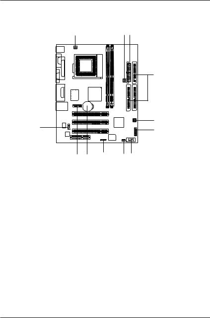
GA-6IWF Series Motherboard Layout
KB_MS
|
COMA |
|
|
|
LPT |
VGA |
|
|
LINE_OUT |
IN |
E |
IN |
LINE_ |
GAM |
MIC_ |
|
|
USB |
|
LAN* |
KINNERETH*
CPU_FAN
SOCKET 370
GMCH
W83627HF
F AUDIO
BATTERY
CD_IN
AC97
CNR
|
|
|
FLOPPY |
|
|
ATXPWR |
|
L) |
|
|
|
GA-6IWF (E or |
|
PWR FAN |
|
|
|
|
|
DIMM1 |
|
DIMM2 |
|
PCI1 |
|
IDE2 |
IDE1 |
|
|
||
PCI2 |
|
SYS |
|
|
|
FAN |
|
|
|
ICH2 |
|
PCI3 |
|
|
|
|
|
F_PANEL |
|
IR |
BIOS |
F_USB |
|
WAKE ON LAN |
|
||
"*" Only for GA-6IWFL.
1 0
Hardware Installation Process
Chapter 2 Hardware Installation Process
To set up your computer, you must complete the following setups:
Step 1- Install the Central Processing Unit (CPU)
Step 2- Install memory modules
Step 3- Install expansion cards
Step 4- Connect ribbon cables, cabinet wires, and power supply
Step 5- Setup BIOS software
Step 6- Install supporting software tools
Step 1 |
Step 2 Step 5 |
|||||
|
|
|
|
|
|
|
|
|
|
|
|
|
|
|
|
|
|
|
|
|
|
|
|
|
|
|
|
Step 4
Step 5
Step 3
Step 5
1 1
GA-6IWF Series Motherboard
Step 1: Install the Central Processing Unit (CPU)
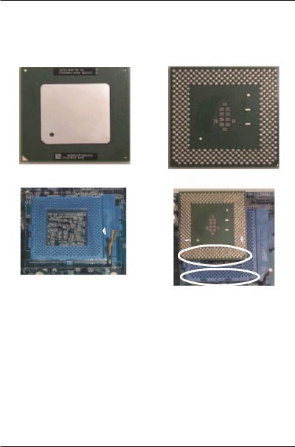
Step1-1: CPU Installation
For example: The newest Pentium III processor (FC-PGA2 package).
CPU Top View
Socket Actuation Lever
1.Pull up the CPU socket level and up to 90-degree angle.
CPU Bottom View
Pin1 indicator
2.Locate Pin 1 in the socket and look for a (golden) cut edge on the CPU upper corner. Then insert the CPU into the socket.
Please make sure the CPU type is supported by the motherboard.
If you do not match the CPU socket Pin 1 and CPU cut edge well, it will cause improper installation. Please change the insert orientation.
1 2
Hardware Installation Process
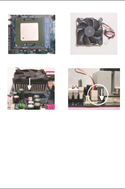
Step1-2:CPU Heat Sink Installation
1.Press down the CPU socket lever and finish CPU installation.
3.Fasten the heatsink supporting-base onto the CPU socket on the mainboard.
2. Use qualified fan approved by Intel.
4.Make sure the CPU fan is plugged to the CPU fan connector, than install complete.
Please use Intel approved cooling fan.
We recommend you to apply the thermal paste to provide better heat conduction between your CPU and heatsink.
Make sure the CPU fan power cable is plugged in to the CPU fan connector, this completes the installation.
Please refer to CPU heat sink user’s manual for more detail installation procedure.
1 3
GA-6IWF Series Motherboard
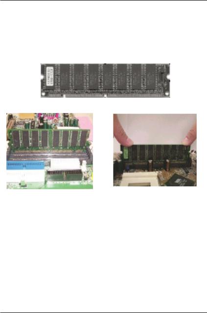
Step 2: Install memory modules
The motherboard has 2 dual in-line memory module (DIMM) sockets support 4 banks. The BIOS will automatically detects memory type and size. To install the memory module, just push it vertically into the DIMM Slot .The DIMM module can only fit in one direction due to the two notch. Memory size can vary between sockets.
SDRAM
1.The DIMM slot has two notch, so the DIMM memory module can only fit in one direction.
2.Insert the DIMM memory module vertically into the DIMM slot. Then push it down.
3.Close the plastic clip at both edges of the DIMM slots to lock the DIMM module. Reverse the installation steps when you wish to remove the DIMM module.
When STR/DIMM LED is ON, do not install/remove SDRAM from socket.
Please note that the DIMM module can only fit in one direction due to the two notches. Wrong orientation will cause improper installation. Please change the insert orientation.
1 4
Hardware Installation Process
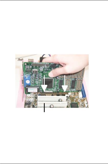
Step 3: Install expension cards
1.Read the related expansion card’s instruction document before install the expansion card into the computer.
2.Remove your computer’s chassis cover, necessary screws and slot bracket from the computer.
3.Press the expansion card firmly into expansion slot in motherboard.
4.Be sure the metal contacts on the card are indeed seated in the slot.
5.Replace the screw to secure the slot bracket of the expansion card.
6.Replace your computer’s chassis cover.
7.Power on the computer, if necessary, setup BIOS utility of expansion card from BIOS.
8.Install related driver from the operating system.
PCI Slot
1 5
GA-6IWF Series Motherboard
Step 4: Connect ribbon cables, cabinet wires, and power
supply |
|
|
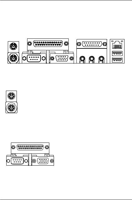
Step4-1:I/O Back Panel Introduction |
|
|
|
|
|
|
|
|
|
|
|
PS/2 Keyboard and PS/2 Mouse Connector
PS/2 Mouse Connector |
This connector supports standard PS/2 keyboard |
(6 pin Female) |
and PS/2 mouse. |
PS/2 Keyboard Connector |
|
(6 pin Female) |
|
Parallel Port , Serial Port and VGA Port (LPT/COMA/VGA)
Parallel Port (25 pin Female)
COMA |
VGA |
Serial Port |
VGA Port |
(9 pin Male) |
(15 pin Female) |
This connector supports 1 standard COM port ,1 Parallel port and 1 VGA port. Device like printercan be connected to Parallel port ; mouse and modem etc can be connected to Serial ports.
1 6
Hardware Installation Process
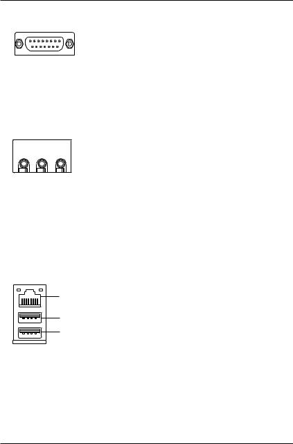
Game /MIDI Ports
Joystick/ MIDI (15 pin Female)
Audio Connectors
|
|
|
|
Line Out |
MIC In |
||
|
|
|
|
Line In
USB & LAN Connector
LAN*
USB 0
USB 1
"*" Only for GA-6IWFL.
This connector supports joystick, MIDI keyboard and other relate audio devices.
After install onboard audio driver, you may connect speaker to Line Out jack, micro phone to MIC In jack. Device like CD-ROM , walkman etc can be connected to Line-In jack.
Before you connect your device(s) into USB connector(s), please make sure your device(s) such as USB keyboard,mouse, scanner, zip, speaker..etc. Have a standard USB interface. Also make sure your OS (Win 95 with USB supplement, Win98, Windows 2000, Windows ME, Win NT with SP 6) supports USB controller. If your OS does not support USB controller, please contact OS vendor for possible patch or driver upgrade. For more information please contact your OS or device(s) vendors.
1 7
GA-6IWF Series Motherboard
Step4-2: Connectors Introduction
A B C
D
L |
E |
|
F |
||
|
|
K J |
I |
H G |
|
|
|
|
A) |
CPU FAN |
H) |
WAKE ON LAN |
|
|
|
|
B) |
PWR FAN |
I ) |
IR |
|
|
|
|
C) |
ATX PWR |
J) |
BATTERY |
|
|
|
|
D) |
Floppy/IDE1/IDE2 |
K) |
F AUDIO |
|
|
|
|
E) |
SYS FAN |
L) |
CD_IN |
|
|
|
|
F) |
F_PANEL |
|
|
|
|
|
|
G) |
F_USB |
|
|
|
|
|
|
1 8
Hardware Installation Process
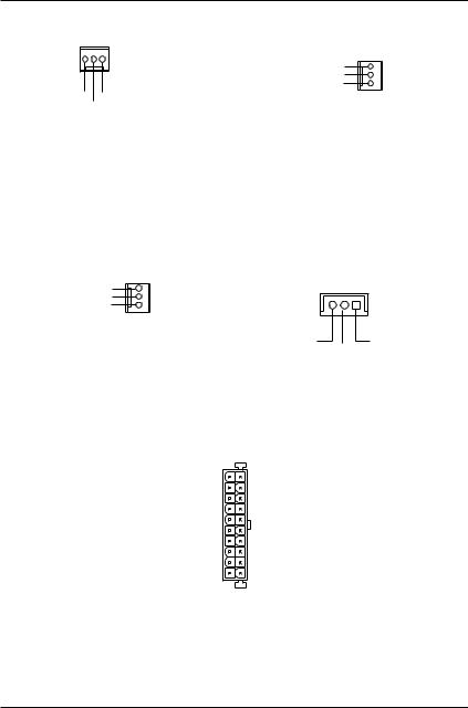
A) CPU_FAN (CPU_FAN Connector) |
E) SYS_FAN (SYS_FAN Connector) |
|
1 |
GND |
1 |
|
||
|
+12V/Control |
|
GND +12V/Control Sense |
Sense |
|
|
|
|
The CPU fan connector supports Max. current up to 600 mA .
B) PWR_FAN (PWR_FAN Connector) H) WAKE ON LAN
GND |
1 |
|
+12V/Control |
|
1 |
Sense |
|
|
|
|
|
|
Signal |
+5V SB |
|
|
GND |
C) ATX PWR (ATX Power)
|
|
|
|
20 |
|
|
+12V |
|
|
|
|
|
VCC |
5V SB (Stand by +5V) |
|
|
|
|
VCC |
|
|
|
|
|
|||
Power Good |
|
|
|
|
-5V |
|
|
|
|
|
|||
GND |
|
|
|
|
GND |
|
|
|
|
|
|||
VCC |
|
|
|
|
GND |
|
|
|
|
|
|||
GND |
|
|
|
|
GND |
|
|
|
|
|
|||
VCC |
|
|
|
|
PS-ON(Soft On/Off) |
|
|
|
|
|
|||
GND |
|
|
|
|
GND |
|
|
|
|
|
|||
3.3V |
|
|
|
|
-12V |
|
|
|
|
|
|||
3.3V |
|
|
|
|
3.3V |
|
1 |
|
|
||||
|
|
|
|
|
||
AC power cord should only be connected to your power supply unit after ATX power cable and other related devices are firmly connected to the mainboard.
1 9
GA-6IWF Series Motherboard
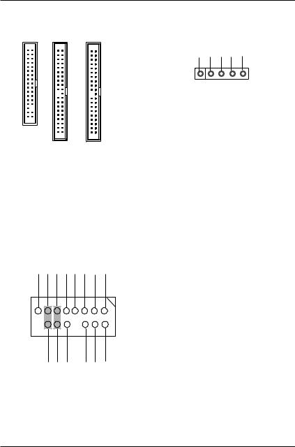
D) Floppy / IDE1 / IDE2
1
Floppy |
IDE1 |
IDE2 |
|
1 |
1 |
K ) Front Audio Connector
Audio(L) Front GND |
Audio(R) Front |
+12V MIC |
GND |
GND |
(R) Speaker Incase |
15 |
|
|
|
|
1 |
16 |
|
|
|
|
2 |
|
|
|
|
|
|
Audio(L) Rear |
Audio(R) Rear |
GND |
GND |
GND |
Speaker Incase |
|
|
|
|
|
(L) |
I ) IR
VCC N C |
IRRX GND IRTX |
1
Be careful with the polarity of the IR connector while you connect the IR. Please contact you nearest dealer for optional IR device.
If you want to use "Front Audio" connector, you must move 11-12,13-14 Jumper.
In order to utilize the front audio header, your chassis must have front audio connector. Also please makesurethepinassigmentonthecable is the same as the pin assigment on the MB header. To find out if the chassis you are buying support front audio connector, please contact your dealer.
2 0
Hardware Installation Process
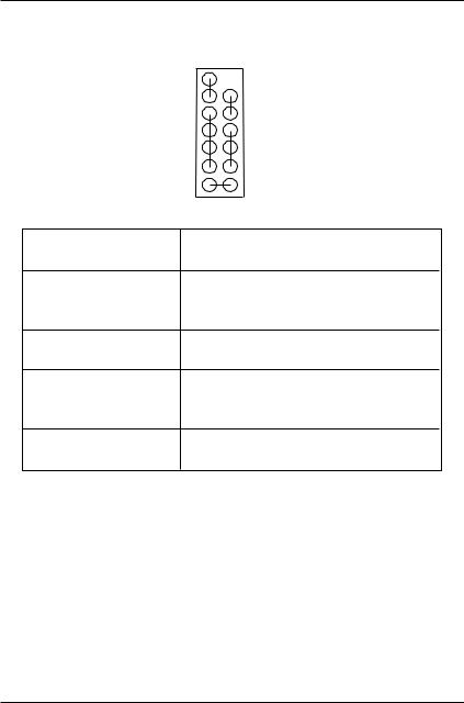
G) F_USB
Power
USB D3-
USB D3+
N C
GND
GND
N C
USB D2+
USB D2-
Power
Be careful with the polarity of the front panel USB connector. Check the pin assignment while you connect the front panel USB cable. Please contact your nearest dealer for optional front panel USB cable.
J ) Battery |
L) CD_IN |
|
|
+ |
CD-R |
|
GND |
|
|
|
|
|
1 |
CD-L |
CAUTION
Danger of explosion if battery is incorrectly replaced.
Replace only with the same or equivalent type recommended by the manufacturer.
Dispose of used batteries according to the manufacturer’sinstructions.
2 1
GA-6IWF Series Motherboard
F) F_PANEL (2x7 pins jumper)
|
14 |
13 |
|
RST |
|
||
|
1 |
PW |
|
|
|
||
SPK |
P+ |
||
P- |
|||
|
|
||
|
|
P- |
|
HD- |
1 HD+ |
||
|
2 |
1 |
|
HD (IDE Hard Disk Active LED) |
Pin 1: LED anode(+) |
||
|
Pin 2: LED cathode(-) |
||
SPK (Speaker Connector) |
Pin 1: VCC(+) |
||
|
Pin 2- Pin 3: NC |
||
|
Pin 4: Data(-) |
||
RST (Reset Switch) |
Open: Normal Operation |
||
|
Close: Reset Hardware System |
||
P+P-P-(Power LED) |
Pin 1: LED anode(+) |
||
|
Pin 2: LED cathode(-) |
||
|
Pin 3: LED cathode(-) |
||
PW (Soft Power Connector) |
Open: Normal Operation |
||
|
Close: Power On/Off |
||
Please connect the power LED, PC speaker, reset switch and power switch etc of your chassis front panel to the front panel jumper according to the pin assignment above.
2 2

BIOS Setup
Chapter 3 BIOS Setup
BIOS Setup is an overview of the BIOS Setup Program. The program that allows users to modify the basic system configuration. This type of information is stored in battery-backed CMOS RAM so that it retains the Setup information when the power is turned off.
ENTERINGSETUP
Power ON the computer and press <Del> immediately will allow you to enter Setup. If the message disappears before you respond and you still wish to enter Setup, restart the system to try again by turning it OFF then ON or pressing the “RESET” bottom on the system case. You may also restart by simultaneously press <Ctrl> - <Alt>- <Del> keys.
CONTROLKEYS
< > |
Move to previous item |
|
|
< > |
Move to next item |
|
|
< > |
Move to the item in the left hand |
|
|
< > |
Move to the item in the right hand |
|
|
<Esc> |
Main Menu - Quit and not save changes into CMOS Status Page Setup Menu and |
|
Option Page Setup Menu - Exit current page and return to Main Menu |
|
|
<+/PgUp> |
Increase the numeric value or make changes |
|
|
<-/PgDn> |
Decrease the numeric value or make changes |
|
|
<F1> |
General help, only for Status Page Setup Menu and Option Page Setup Menu |
|
|
<F2> |
Reserved |
|
|
<F3> |
Reserved |
|
|
<F4> |
Reserved |
|
|
<F5> |
Restore the previous CMOS value from CMOS, only for Option Page Setup Menu |
|
|
<F6> |
Load the default CMOS value from BIOS default table, only for Option Page Setup |
|
Menu |
|
|
<F7> |
Load the Setup Defaults |
|
|
<F8> |
Reserved |
|
|
<F9> |
Reserved |
|
|
<F10> |
Save all the CMOS changes, only for Main Menu |
|
|
2 3

GA-6IWF Series Motherboard
GETTINGHELP
Main Menu
The on-line description of the highlighted setup function is displayed at the bottom of the screen.
Status Page Setup Menu / Option Page Setup Menu
Press F1 to pop up a small help window that describes the appropriate keys to use and the possible selections for the highlighted item. To exit the Help Window press <Esc>.
The Main Menu (For example: BIOS Ver. :F2)
Once you enter AWARD BIOS CMOS Setup Utility, the Main Menu (Figure 1) will appear on the screen. The Main Menu allows you to select from eight setup functions and two exit choices. Use arrow keys to select among the items and press <Enter> to accept or enter the sub-menu.
CMOS Setup Utility-Copyright (C) 1984-2001 Award Software
Standard CMOS Features |
Frequency/Voltage Control |
Advanced BIOS Features |
Load Fail-Safe Defaults |
Advanced Chipset Features |
Load Optimized Defaults |
Integrated Peripherals |
Set Supervisor Password |
Power Management Setup |
Set User Password |
PnP/PCI Configurations |
Save & Exit Setup |
PC Health Status |
Exit Without Saving |
|
|
ESC:Quit |
:Select Itect |
F10:Save & Exit Setup |
|
Time, Date, Hard Disk Type...
Figure 1: Main Menu
Standard CMOS Features
This setup page includes all the items in standard compatible BIOS.
Advanced BIOS Features
This setup page includes all the items of Award special enhanced features.
Advanced Chipset Features
This setup page includes all the items of chipset special features.
2 4

BIOS Setup
Integrated Peripherals
This setup page includes all onboard peripherals.
Power Management Setup
This setup page includes all the items of Green function features.
PnP/PCI Configurations
This setup page includes all the configurations of PCI & PnP ISA resources.
PC Health Status
This setup page is the System auto detect Temperature, voltage, fan, speed.
Frequency/Voltage Control
This setup page is control CPU’s clock and frequency ratio.
Load Fail-Safe Defaults
Fail-Safe Defaults indicates the value of the system parameters which the system would be in safe configuration.
Load Optimized Defaults
Optimized Defaults indicates the value of the system parameters which the system would be in best performance configuration.
Set Supervisor password
Change, set, or disable password. It allows you to limit access to the system and Setup, or just to Setup.
Set User password
Change, set, or disable password. It allows you to limit access to the system.
Save & Exit Setup
Save CMOS value settings to CMOS and exit setup.
Exit Without Saving
Abandon all CMOS value changes and exit setup.
2 5
 Loading...