


GA-5EXSH-RH
Pentium® 4/D Processor Motherboard
USER’S MANUAL
Pentium® 4/D Processor Motherboard Rev. 1001 12ME-5EXSHRH-1001R
*The WEEE marking on the product indicates this product must not be disposed of with user's other household waste and must be handed over to a designated collection point for the recycling of waste electrical and electronic equipment!!
*The WEEE marking applies only in European Union's member states.

GA-5EXSH-RH Motherboard |
|
Table of Content |
|
Item Checklist ......................................................................................... |
4 |
WARNING! ............................................................................................... |
4 |
Chapter 1 Introduction ............................................................................ |
5 |
1.1 Features Summary ................................................................................ |
5 |
1.2 GA-5EXSH-RH Motherboard Components .......................................... |
8 |
Chapter 2 Hardware Installation Process ............................................. |
10 |
2-1: Installing Processor and CPU Haet Sink ........................................... |
10 |
2-1-1: Installing CPU ....................................................................................................... |
10 |
2-1-2: Installing Heat Sink ................................................................................................ |
11 |
2-2: Install Memory Modules ..................................................................... |
12 |
2-3: Connect ribbon cables, cabinet wires, and power supply ................ |
14 |
2-3-1 : I/O Back Panel Introduction ................................................................................ |
14 |
2-4: Connectors Introduction & Jumper Setting ........................................ |
16 |
2-5: Block Diagram ................................................................................... |
25 |
Chapter 3 BIOS Setup .......................................................................... |
26 |
Main ........................................................................................................... |
28 |
Advanced Processor Options ........................................................................................ |
31 |
Advanced ................................................................................................... |
34 |
Memory Configuration ..................................................................................................... |
35 |
PCI Configuration ............................................................................................................. |
36 |
SIO ITE8718F Configuration ........................................................................................... |
37 |
Advanced Chipset Control ............................................................................................. |
42 |
Hardware Monitor ............................................................................................................ |
44 |
Security ...................................................................................................... |
47 |
Server ......................................................................................................... |
49 |
System Management ...................................................................................................... |
50 |
Console Redirection ........................................................................................................ |
51 |
Event Log Configuration .................................................................................................. |
53 |
Boot ............................................................................................................ |
56 |
Exit ............................................................................................................. |
57 |
2

|
Table of Content |
Chapter 4 INTEL RAID BIOS Configuration ........................................... |
63 |
Chapter 5 Application Driver Installation ............................................... |
68 |
A. Intel Chipset Software Installation Utilities ................................................................ |
68 |
B. Intel LAN Driver Installation ...................................................................................... |
71 |
C. XGI VGA Driver Installation ....................................................................................... |
75 |
D. Intel ICH7R RAID Driver Installation .......................................................................... |
78 |
E. Matrix Storgae Manager Utility Installation ............................................................. |
80 |
F. DirectX 9.0C Driver Installation ................................................................................. |
84 |
Chapter 6 Appendix .............................................................................. |
87 |
3

|
GA-5EXSH-RH Motherboard |
|
|
Item Checklist |
|
|
The GA-5EXSH-RH motherboard |
Serial ATA cable x 4 |
|
IDE (ATA100 ) cable x 1 / Floppy cable x 1 |
I/O Shield Kit |
|
CD for motherboard driver & utility |
SATA Power cable x 2 |
|
GA-5EXSH-RH user’s manual |
USB2.0 cable x 2 |

 WARNING!
Computer motherboards and expansion cards contain very delicate Integrated Circuit (IC) chips. To protect them against damage from static electricity, you should follow some precautions whenever you work on your computer.
1.Unplug your computer when working on the inside.
2.Use a grounded wrist strap before handling computer components. If you do not have one, touch both of your hands to a safely grounded object or to a metal object, such as the power supply case.
3.Hold components by the edges and try not touch the IC chips, leads or connectors, or other components.
4.Place components on a grounded antistatic pad or on the bag that came with the components whenever the components are separated from the system.
5.Ensure that the ATX power supply is switched off before you plug in or remove the ATX power connector on the motherboard.
Installing the motherboard to the chassis…
If the motherboard has mounting holes, but they don’t line up with the holes on the base and there are no slots to attach the spacers, do not become alarmed you can still attach the spacers to the mounting holes. Just cut the bottom portion of the spacers (the spacer may be a little hard to cut off, so be careful of your hands). In this way you can still attach the motherboard to the base without worrying about short circuits. Sometimes you may need to use the plastic springs to isolate the screw from the motherboard PCB surface, because the circuit wire may be near by the hole. Be careful, don’t let the screw contact any printed circuit write or parts on the PCB that are near the fixing hole, otherwise it may damage the board or cause board malfunctioning.
4

Introduction
Chapter 1 Introduction
1.1Features Summary
Form Factor |
y |
9.6” x 9.6” m ATX form factor, 6 layers PCB. |
CPU |
y |
Supports single Intel® Pentium® 4/Pentium® D processor |
|
|
in LGA775 socket |
|
y Intel Pentium® Dual Core(Smithfield/800 MHz ) Processor |
|
|
y Intel Pentium® Quad Code (Kentsfield) Processor |
|
|
y |
Supports 800/1066MHz FSB |
|
y L2 cache on-die per processor from 4M |
|
|
|
|
Chipset |
y |
Intel® 3000 Chipset |
|
y |
Intel® ICH7R |
|
y |
Intel® PXH-V |
Memory |
y |
4 x DDRII DIMM sockets |
|
y |
Supports up to 8GB 533/667 memory |
|
y Dual Channel memory bus |
|
|
y ECC Unbuffered DDRII 533/667 |
|
|
y Supports 512MB, 1GB, and 2GB memory |
|
|
|
|
I/O Control |
y |
ITE IT8718F Super I/O |
Expansion Slots |
y |
Supports 1 PCI slot 32-Bit/33MHz (5V) |
|
y Supports 2 PCI-X slots 64-Bit/100MHz |
|
|
y Supports 1 PCI-Express x8 slot |
|
|
|
|
SATA RAID Controller |
y |
Built in Intel® ICH7R with Software RAID 0,1,10, 5 |
|
y |
Supports 4 SATA 3.0 Gb/s connectors |
|
|
|
On-Board Graphic |
y |
XGI Volari Z7 |
|
y |
16MB SDRAM |
|
|
|
On-Board Peripherals |
y |
1 ATA 100 connector |
|
y |
1 Floppyport supports 360K, 720K,1.2M, 1.44M and |
|
|
2.88M bytes. |
|
y |
2 PS/2 connectors |
|
y 1 Parallel port supports Normal/EPP/ECP mode |
|
|
y 2 Serial port (COM, 1 by cable) |
|
|
y 4 x USB 2.0 (2 by cable) |
|
|
y |
1 VGA connector |
|
y 2 x LAN RJ45 |
|
|
y |
4 x SATA 3.0 Gb/s connectors |
5

GA-5EXSH-RH Motherboard
Hardware Monitor |
y |
Enhanced features with CPU Vcore, 1.5V reference, |
|
|
|
VCC3 (3.3V) , VBAT3V, +5VSB, CPUA/B Temperature, |
|
|
|
and System Temperature Values viewing |
|
|
y |
CPU/Power/System Fan Revolution Detect |
|
|
y |
CPU shutdown when overheat |
|
|
y |
System Voltage Detect |
|
|
|
|
|
On-Board LAN |
y |
Intel® 82573L and Intel® 82573V GbE controllers |
|
|
y |
Supports WOL, PXE |
|
|
y |
Intel® 82573V supports flexible hardware design to switch |
|
|
|
remote transactions through IPMI interface |
|
|
|
|
|
BIOS |
y |
Phoenix BIOS on 8Mb flash ROM |
|
Special Features |
y |
Ehanced feature with GSMT Lite Utility |
|
|
|
|
|
Server Manageability (Optionall) |
y |
IPMI 2.0 module |
|
AdditionalFeatures |
y |
PS/2 Mouse wake up from S1 under Windows Operating |
|
|
|
System |
|
|
y |
External Modem wake up |
|
|
y |
Supports S1, S4, S5 under Windows Operating System |
|
|
y |
Wake on LAN (WOL) |
|
|
y |
Wake on Ring (WOR) |
|
|
y |
AC Recovery |
|
|
y |
Supports Console Redirection |
|
|
y |
Supports 4-pin Fan controller |
|
|
|
|
|
6

Introduction
7

GA-5EXSH-RH Motherboard
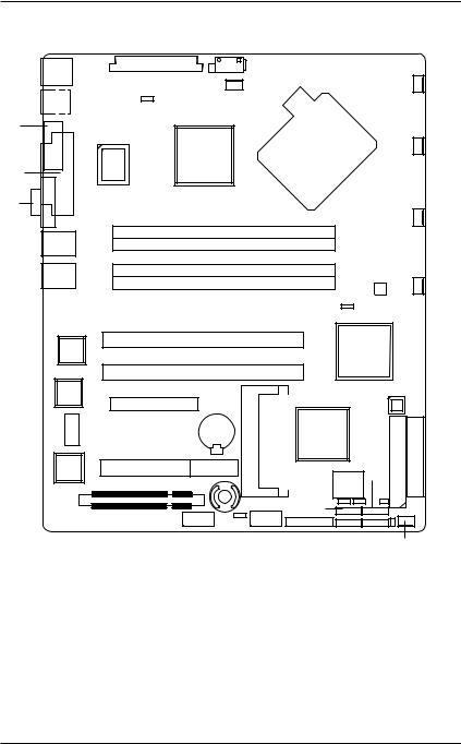
1.2 GA-5EXSH-RH Motherboard Components
1. |
CPU |
25. |
PCI1 Slot(32bit/33MHz) |
2. |
Intel 3000 |
26. |
PCI-X1 Slot (64bit/100MHz) |
3. |
Intel ICH7R |
27. |
PCI-X2 Slot (64bit/100MHz) |
4. |
Intel PXH-V |
28. |
PCI-E x8 Slot |
5. |
XGI Volari Z7 |
29. |
IPMI Connector |
6. |
Hynix 606T |
30. |
SO-DIMM |
7. |
ITE IT8718F |
31. |
DDRII 1 |
8. |
Intel 82573V GbE |
32. |
DDRII 2 |
9. |
Intel 82573L GbE |
33. |
DDRII 3 |
10. |
IDE Connector |
34. |
DDRII 4 |
11. |
Floppy Connector |
35. |
RJ45 LAN Port |
12. |
COM2 Connector |
|
(Support IPMI 2.0/Optional) |
13. |
USB2 Connector |
36. |
RJ45 LAN Port |
14. |
Windbond W83792G |
37. |
VGAPort |
15. |
SATA1 Connector |
38. |
Parallel Port |
16. |
SATA2 Connector |
39. |
COM Port |
17. |
SATA3 Connector |
40. |
USB Ports |
18. |
SATA4 Connector |
41. |
PS/2 Connectors |
19. |
UF1 (System Fan Connector) |
42. |
BIOS Flash |
20. |
UF2 (System Fan Connector) |
43. |
Battery |
21. |
UF3 (System Fan Connector) |
44. |
ibutton |
22. |
UF4 (System Fan Connector) |
45. |
Auxiliary Power (ATX1) |
23. |
UF5 (CPU Fan Connector) |
46. |
Auxiliary Power (ATX 12V) |
24.UF6 (System Fan Connector)
8
Introduction
41
40
39
38
37
35
36
8
9
6
5
29
45 456
|
23 |
7 |
2 |
|
31
32
33 34
26
27
28
43 30
25
44
12 13
19
120
21
|
|
22 |
|
4 |
|
|
14 |
|
3 |
|
|
|
|
10 |
42 |
18 |
11 |
17 |
|
|
16 |
15 |
|
|
|
24 |
9
GA-5EXSH-RH Motherboard
Chapter 2 Hardware Installation Process
2-1: Installing Processor and CPU Haet Sink
Before installing the processor and cooling fan, adhere to the following cautions:
1. The processor will overheat without the heatsink and/or fan, resulting in permanent irreparable damage.
2.Never force the processor into the socket.
3.Apply thermal grease on the processor before placing cooling fan.
4.Please make sure the CPU type is supported by the motherboard.
5.If you do not match the CPU socket Pin 1 and CPU cut edge well, it may damage the CPU. Please change the insert orientation.
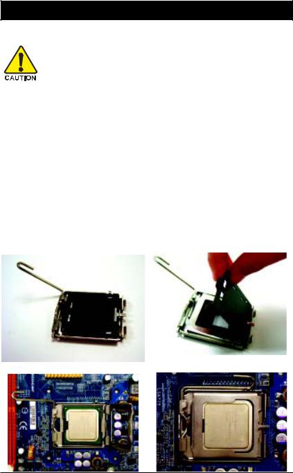
2-1-1: Installing CPU
Step 1 Raise the metal locking lever on the socket. Step 2 Remove the plastic covering on the CPU socket. Step 3 Lift the metal cover.
Step 4 Insert the CPU with the correct orientation. The CPU only fits in one orientation. Step 5 Once the CPU is properly placed, please replace the metal cover and push the metal
lever back into locked position.
1 0
Hardware Installation Process
2-1-2: Installing Heat Sink
Male Push Pin
 The top of Female Push Pin
Female Push Pin
Step 1.
Please apply heat sink paste on the surface of the installed CPU.
Step. 3
Place the heat sink on top the CPU and make sure the push pins align to the pin hole on the motherboard.Push down the push pins diagonally.
Step. 5
Please check the back side of teh motherboard. Make sure the push pin is seated firmly as the picture shown.
Step. 2
( to remove the heat sink, turning the push pin along the direction of arrow; and reverse the previous step to install the heat sink.)
Please note the direction of arrow sign on the male push pin doesn't face inwards before installation. (This instruction is only for Intel boxed fan)
Step. 4
Please make sure the Male and Female push pin are brought together. (for detailed installation instructions, please refer to the heat sink installation section of the user manual)
Step 6.
Attach the power connector of the heat sink to the CPU fan header located on the motherboard. Heat sink installation is completed.
1 1
GA-5EXSH-RH Motherboard
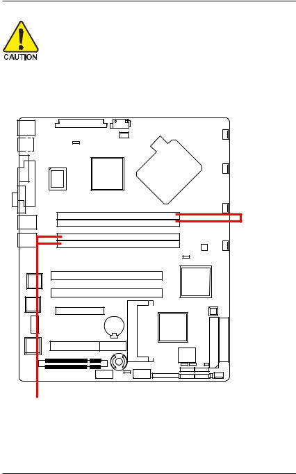
2-2: Install Memory Modules
Before installing the processor and heatsink, adhere to the following warning: When DIMM LED is ON, do not install/remove DIMM from socket.
GA-5EXSH-RH has 4 dual inline memory module (DIMM) sokcets. It supports Dual Channels Technology. The BIOS will automatically detects memory type and size during system boot. For detail DIMM installation, please refer to the following instructions.
Channel A
Channel B
1 2
Hardware Installation Process
Table 1. Supported DIMM Module Type
Size |
Organization |
RAM Chips/DIMM |
|
|
|
256MB |
8MB x 8 x 4 bks |
8 |
|
16MB x 4 x 4bks |
16 |
512MB |
16MB x 8 x 4bks |
8 |
|
32MB x 4 x 4bks |
16 |
1GB |
32MB x 8 x 4bks |
8 |
|
64MB x 4 x 4bks |
16 |
|
|
|
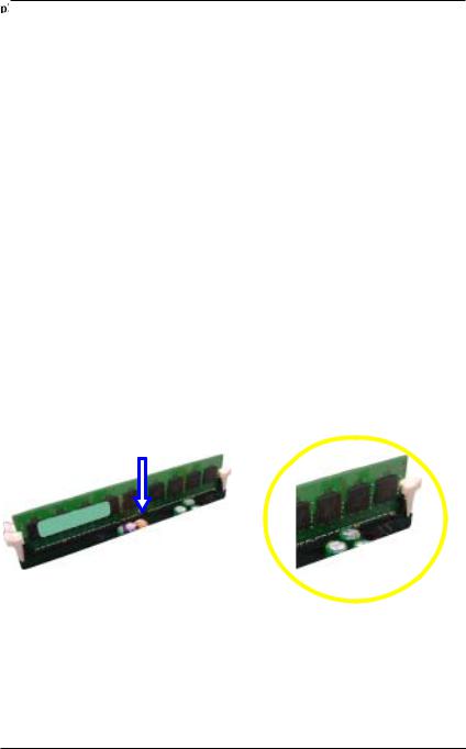
Installation Steps:
1.Unlock a DIMM socket by pressing the retaining clips outwards.
2.Aling a DIMM on the socket such that the notch on the DIMM exactly match the notch in the socket.
3.Firmly insert the DIMMinto the socket until the retaining clips snap back in place.
4.When installing the memory into the DIMM socket, we recommend to populate the memory as a pair. One in Channel A module and one in Channel B module for best performance. Please populate DIMM starting from Channel A (Yellow slot).
Note that each logical DIMM must be made of two identical DIMMs having the same device size on each and the same DIMM size.
5.Reverse the installation steps if you want to remove the DIMM module.
1 3
GA-5EXSH-RH Motherboard
2-3: Connect ribbon cables, cabinet wires, and power supply
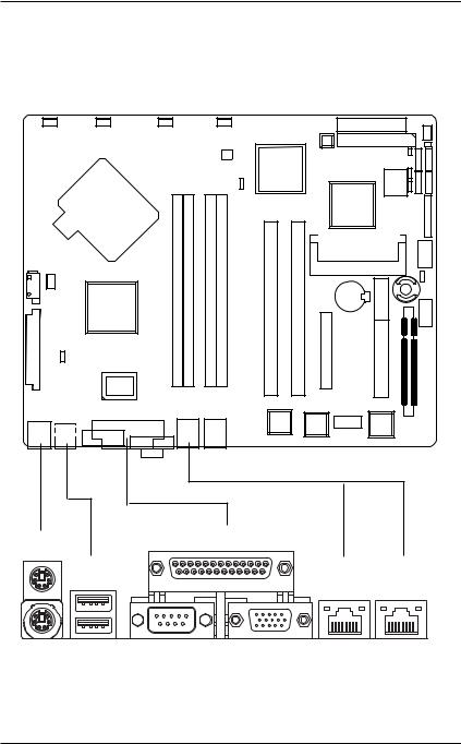
2-3-1 : I/O Back Panel Introduction
X Z
Y
] ^
[\
1 4
Hardware Installation Process
XPS/2 Keyboard and PS/2 Mouse Connector
To install a PS/2 port keyboard and mouse, plug the mouse to the upper port (green) and the keyboard to the lower port (purple).
YUSB Ports
Before you connect your device(s) into USB connector(s), please make sure your device(s) such as USB keyboard, mouse, scanner, zip, speaker...etc. have a standard USB interface.
Also make sure your OS supports USB controller. If your OS does not support USB controller, please contact OS vendor for possible patch or driver updated. For more information please contact your OS or device(s) vendors.
ZParallel Port
The parallel port allows connection of a printer, scanner and other peripheral devices.
[Serial Port
Modem can be connected to Serial port.
\VGA Port
Monitor can be connected to VGA port.
]LAN Port
The LAN port provides Internet connection of Gigabit Ethernet with data transfer speeds of 10/100/1000Mbps. This port supports IPMI 2.0.
^LAN Port
The LAN port provides Internet connection of Gigabit Ethernet with data transfer speeds of 10/100/1000Mbps.
LAN LED Description
LED2 (Green/Yellow) |
|
|
|
|
|
|
|
|
|
|
|
LED1 (Green) |
|
|
|
|
|
|
|
|
|
|
|
|
|
|
|
|
|
|
|
|
|
|
|
|
|
|
|
|
|
|
|
|
|
|
|
|
|
|
|
|
|
|
|
|
|
|
|
|
|
||||||||
Name |
Color |
Condition |
|
|
Description |
||||||||
LED1 |
Green |
O N |
|
|
LAN Link / no Access |
||||||||
|
Green |
BLINK |
|
|
LAN Access |
||||||||
|
- |
OFF |
|
|
Idle |
||||||||
|
- |
OFF |
|
|
10Mbps connection |
||||||||
LED2 |
|
|
|||||||||||
|
- |
OFF |
|
|
Port identification with 10 Mbps connection |
||||||||
|
Green |
ON |
|
|
100Mbps connection |
||||||||
|
Green |
BLINK |
|
|
Port identification with 100Mbps connection |
||||||||
|
Yellow |
ON |
|
|
1Gbps connection |
||||||||
|
Yellow |
BLINK |
|
|
Port identification with 1Gbps connection |
||||||||
|
|
|
|
|
|
|
|
|
|
|
|
|
|
NOTE!! LED1 will NOT function under 10Mbps environment.
1 5
GA-5EXSH-RH Motherboard
2-4: Connectors Introduction & Jumper Setting
2
1
15 |
14 |
|
13 |
12
11
|
|
17 |
|
|
|
3 |
|
|
|
|
|
20 |
|
8 |
4 |
|
|
|
9 |
10 |
7 |
6 |
5 |
|
|
16 |
|
18 |
|
|
|||||
|
|
19 |
|
|
|
|||
|
|
|
|
|
|
|
|
|
1. |
ATX1 |
11. |
UF1 (System Fan Connector) |
|||||
2. |
ATX2 |
12. |
UF2 (System Fan Connector) |
|||||
3. |
IDE1 (IDE Connector) |
13. |
UF3 (System Fan Connector) |
|||||
4. |
FDC1 (Floppy Connector) |
14. |
UF4 (System Fan Connector) |
|||||
5. |
SATA 1 (SATA Connector) |
15. |
UF5 (CPU Fan Connector) |
|||||
6. |
SATA 2 (SATA Connector) |
16. |
UF6 (System Fan Connector) |
|||||
7. |
SATA 3 (SATA Connector) |
17. BAT1 (Battery) |
|
|
|
|||
8. |
SATA 4 (SATA Connector) |
18. |
F_Panel (Front Panel Connector) |
|||||
9. |
COM2 |
19. |
CLR_CMOS (Clear CMOS Jumper) |
|||||
10. |
USB2 (Front USB Connector) |
20. |
RECOVERY1 (Recovery Jumper) |
|||||
1 6

ConnectorIntroduction
1) ATX1 (Auxukiary Power Connector)
1 |
12 |
13 |
24 |
AC power cord should only be connected to your power supply unit after ATX power cable and other related devices are firmly connected to the mainboard.
PIN No. Definition
1+3.3V
2+3.3V
3GND
4+5V
5GND
6+5V
7GND
8POK
95VSB
10+12V
11+12V
12+3.3V
13+3.3V
14-12V
15GND
16PSON
17GND
18GND
19GND
20-5V
21+5V
22+5V
23+5V
24GND
2 ) ATX2 (Auxukiary +12V Power Connector)
1 |
4 |
|
5 |
8 |
|
|
|
|
Pin No. |
Definition |
|
|
1 |
GND |
|
2 |
GND |
|
3 |
GND |
|
4 |
GND |
|
5 |
P12V_CPU1 |
|
6 |
P12V_CPU1 |
|
7 |
P12V_CPU0 |
|
8 |
P12V_CPU0 |
This connector (ATX +12V) is used only for
CPU Core Voltage.
1 7
GA-5EXSH-RH Motherboard
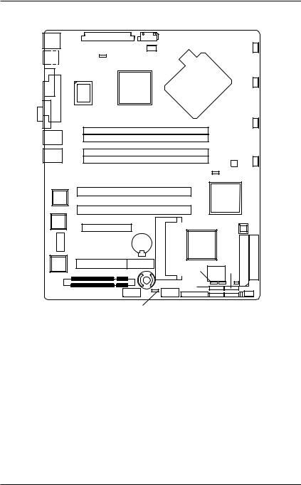
3 ) IDE1 (IDE Connector)
Please connect first harddisk to IDE1. The red stripe of the ribbon cable must be the same side with the Pin1.
40 2
39 1
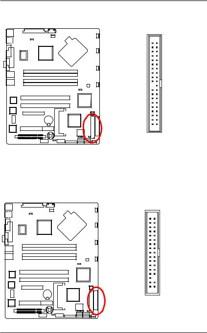
4 ) FDC1 (Floppy Connector)
Please connect the floppy drive ribbon cables to FDD. It supports 720K,1.2M,1.44M and 2.88Mbytes floppy disk types. The red stripe of the ribbon cable must be the same side with the Pin1.
33 34
1 2
1 8
ConnectorIntroduction
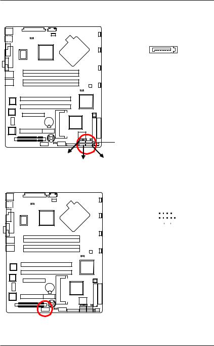
5/ 6/ 7/ 8 ) SATA 1~4 (Serial ATA Connectors)
You can connect the Serial ATA device to this connector, it provides you high speed transfer rates (3.0Gb/s).
7 |
1 |
|
|
|
|
|
|
|
Pin No. |
Definition |
|
|
|
|
|
|
1 |
GND |
|
|
2 |
TXP |
|
|
3 |
TXN |
|
|
4 |
GND |
|
|
5 |
RXN |
|
|
6 |
RXP |
|
|
7 |
GND |
|
 SATA4
SATA4
SATA3
SATA2 SATA1
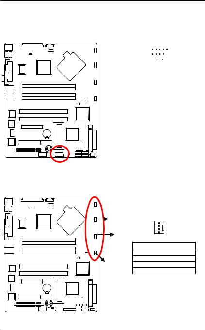
9 ) COM2
1 |
9 |
|
||
|
|
|
|
|
|
|
|
|
|
2 |
10 |
|
||
|
|
|
|
|
Pin No. |
Definition |
|||
1 |
|
|
DCD- |
|
2 |
|
|
SIN2 |
|
3 |
|
|
SOUT2 |
|
4 |
|
|
DTR2- |
|
5 |
|
|
GND |
|
6 |
|
|
DSR2- |
|
7 |
|
|
RTS2- |
|
8 |
|
|
CTS2- |
|
9 |
|
|
RI2- |
|
10 |
|
|
NC |
|
1 9
GA-5EXSH-RH Motherboard
10 ) USB2 (Front USB Connector)
Be careful with the polarity of the front USB connector. Check the pin assignment carefully while you connect the front USB cable, incorrect connection between the cable and connector will make the device unable to work or even damage it. For optional front USB cable, please contact your local dealer.
2 |
10 |
|
||||
|
|
|
|
|
|
|
|
|
|
|
|
|
|
1 |
9 |
|
||||
|
|
|
|
|
|
|
Pin No. |
|
Definition |
||||
1 |
|
|
|
Power |
||
2 |
|
|
|
Power |
||
3 |
|
|
|
USB Dx- |
||
4 |
|
|
|
USB Dy- |
||
5 |
|
|
|
USB Dx+ |
||
6 |
|
|
|
USB Dy+ |
||
7 |
|
|
|
GND |
||
8 |
|
|
|
GND |
||
9 |
|
|
|
No Pin |
||
10 |
|
|
NC |
|||
|
|
|
|
|
|
|
11/ 12/13/14/16 ) UF1/2/3/4/6 (System Fan Connectors)
This connector allows you to link with the cooling fan on the system case to lower the system temperature. These connectors are for system use only.

 UF1
UF1
UF2 |
|
1 |
|
|
|
||
UF3 |
|
|
|
|
Pin No. |
Definition |
|
|
1 |
GND |
|
|
2 |
12V |
|
UF4 |
3 |
Sense |
|
4 |
Control |
||
|
2 0
ConnectorIntroduction
15 ) UF5 (CPU Fan Connectors)
Please note, a proper installation of the CPU cooler is essential to prevent the CPU from running under abnormal condition or damaged by overheating.The CPU fan connector supports Max. current up to 1A .
1
Pin No. |
Definition |
1 |
GND |
2 |
12V |
3 |
Sense |
4 |
Control |
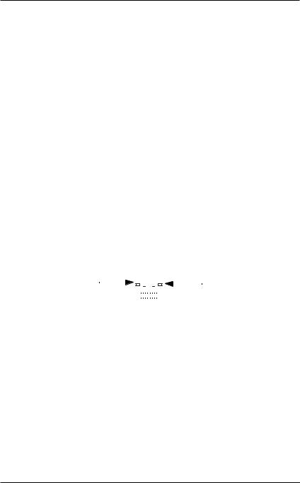
17 ) Battery
If you want to erase CMOS...
1.Turn OFF the computer and unplug the power cord. 2.Remove the battery, wait for 30 second. 3.Re-install the battery.
4.Plug the power cord and turn ON the computer.
CAUTION
Danger of explosion if battery is incorrectly replaced.
Replace only with the same or equivalent type recommended by the manufacturer. Dispose of used batteries according to the manufacturer’sinstructions.
2 1
GA-5EXSH-RH Motherboard
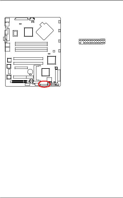
18 ) F_Panel (2X12 Pins Front Panel connector)
Please connect the power LED, PC speaker, reset switch and power switch of your chassis front panel to the F_PANEL connector according to the pin assignment above.
2 |
24 |
1 |
23 |
Pin No. |
Signal Name |
Description |
1. |
PWLED+ |
Power LED Signal anode (+) |
2. |
5VSB |
P5V Stand By Power |
3. |
KEY |
Pin Removed |
4. |
ID_LED+ |
ID LED Signal anode (+) |
5. |
PWLED- |
Power LED Signal cathode(-) |
6. |
ID_LED- |
ID LED Signal cathode(-) |
7. |
HD+ |
Hard Disk LED Signal anode (+) |
8. |
F_SYSRDY |
System Fan Fail LED Signal |
9. |
HD- |
Hard Disk LED Signal cathode(-) |
10. |
F_SYSTATUS |
System Status LED Signal |
11. |
PWB+ |
Power Button Signal anode (+) |
12. |
L1_ACT |
LAN1 access LED Signal |
13. |
PWB+_GND |
Power Button Ground |
14. |
L1_LNK- |
LAN1 linked LED Signal cathode(-) |
15. |
RST_BTN- |
Reset Button cathode(-) |
16. |
SENSOR_SDA |
SMBus Data |
17. |
RST_BTN_GND |
Reset Button Ground |
18. |
SENSOR_SCL |
SMBus Clock |
19. |
ID_SW- |
ID Switch Signal cathode(-) |
20. |
CASE_OPEN- |
Chassis intrusion Signal |
21. |
ID_SW-_GND |
ID Switch Ground |
22. |
L2_ACT |
LAN2 access LED Signal |
23. |
NMI_SW- |
NMI Switch cathode(-) |
24. |
L2_LNK- |
LAN2 linked LED Signal cathode(-) |
2 2
ConnectorIntroduction
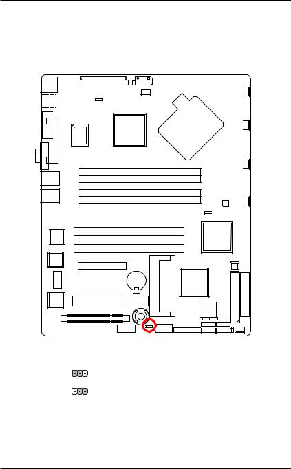
19 ) CLR_CMOS1 (Clear CMOS Function)
You may clear the CMOS data to restore its default values by this jumper.
Default value doesn’t include the “Shunter” to prevent from improper use this jumper. To clear CMOS, temporarily short 2-3 pin.
1 |
1-2 Close: Clear CMOS |
1 |
2-3 Close: Normal (Default value) |
2 3
GA-5EXSH-RH Motherboard
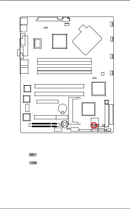
20 ) RECCOVERY1 ( BIOS Recovery Function)
1 |
1-2 Close: Enable BIOS Recovery function. |
1 |
2-3 Close: Normal (Default value) |
2 4

|
|
|
|
|
|
|
|
|
|
|
|
|
|
|
|
|
|
|
|
|
|
|
|
|
|
|
|
|
|
|
|
|
|
|
|
|
|
|
|
|
|
|
|
|
Block Diagram |
||||
2-5: Block Diagram |
|
|
|
|
|
|
|
|
|
|
|
|
|
|
|
|
|
|
|
|
|
|
|
|
|
||||||||||||||||||||||||
|
|
|
|
|
|
|
|
|
|
|
|
|
|
|
|
|
|
|
|
|
|
|
|
|
|
|
|
|
|
|
|
|
|
|
|||||||||||||||
|
|
CLOCK GENERATOR |
|
|
|
|
|
|
|
|
|
|
|
|
|
|
|
|
|
|
|
|
|
|
|
|
|
|
|
|
|
|
|
|
|
|
|||||||||||||
|
|
CK410M ICS ICS954148 |
|
|
|
|
|
|
|
|
|
|
|
|
|
|
|
|
|
|
|
|
|
|
|
|
|
|
|
|
|
|
|
|
|
|
|||||||||||||
|
|
|
|
|
|
INTEL LGA775 |
|
|
|
|
|
|
|
|
|
VRD 11 |
|
|
|
||||||||||||||||||||||||||||||
|
|
|
|
|
|
|
|
|
|
|
|
|
|
|
|
|
|
|
|
|
|
|
|
|
|
|
|
|
|
|
|
|
|
|
|||||||||||||||
|
|
|
|
|
|
|
|
|
|
|
|
|
|
|
|
|
|
|
|
Pentium 4/Pentium D |
|
|
|
|
|
|
|
|
|
ISL6326 |
|
|
|
||||||||||||||||
|
|
|
|
|
|
|
|
|
|
|
|
|
|
|
|
|
|
|
|
Presler / Cedar Mill Core |
|
|
|
|
|
|
|
|
|
|
|
|
|
|
|
|
|||||||||||||
|
|
|
|
|
|
|
|
|
|
|
|
|
|
|
|
|
|
|
|
|
|
|
|
|
|
|
|
|
|
|
|
|
|
|
|||||||||||||||
|
|
|
|
|
|
|
|
|
|
|
|
|
|
|
|
|
|
|
|
|
|
FSB 1066/800/533 |
|
|
|
|
|
|
|
|
|
|
|
|
|
|
|
|
|||||||||||
|
|
|
|
|
|
|
|
|
|
|
|
|
|
|
|
|
|
|
|
|
|
|
|
|
|
|
|
|
|
|
|
|
|
|
|
|
|
|
|
|
|
|
|
|
|
|
|
|
|
|
|
|
|
|
|
|
|
|
|
|
|
|
|
|
|
|
|
|
|
|
|
|
|
|
|
|
|
|
|
|
|
|
|
|
|
|
|
|
|
|
|
|
|
|
|
|
|
|
|
|
|
|
|
|
|
|
|
|
|
|
|
|
|
|
|
|
|
|
|
|
|
|
|
|
|
|
|
|
|
|
|
|
|
|
|
|
|
|
|
|
|
|
|
|
|
|
|
|
|
|
|
|
|
|
|
|
|
|
|
|
|
PCIE x8 |
|
|
|
|
|
|
|
|
|
|
|
|
|
|
|
|
|
|
CHANNEL A |
|
|
|
|||||||||||||||
|
|
PCIE x8 Slot |
|
|
|
|
|
|
|
|
|
|
|
|
|
|
|
|
|
|
|
|
|
|
|
|
|||||||||||||||||||||||
|
|
|
|
|
|
|
|
|
|
|
|
|
|
|
|
|
|
MCH |
|
|
|
|
|
|
DDRII533/667 Un-Buffered ECC |
|
|||||||||||||||||||||||
|
|
|
|
|
|
|
|
|
|
|
|
|
|
|
|
|
|
|
|
|
|
|
|
|
|||||||||||||||||||||||||
|
|
|
|
|
|
|
|
|
|
|
|
|
|
|
|
|
|
|
|
|
|
|
|
|
|
|
|
|
|
|
|
||||||||||||||||||
|
|
|
|
|
|
|
|
|
|
|
|
|
|
|
|
|
|
|
|
|
|
|
|
|
|
|
|
|
|
|
DIMM x 2 (2G one DIMM) |
|
|
|
|||||||||||||||
|
|
|
|
|
|
|
|
|
|
|
|
|
|
|
|
|
|
|
|
|
|
|
INTEL3000 |
|
|
|
|
|
|
|
|||||||||||||||||||
|
|
|
|
|
|
|
|
|
|
|
|
|
|
|
|
|
|
|
|
|
|
|
|
|
|
|
|
|
|
||||||||||||||||||||
|
|
|
|
|
|
|
|
|
|
|
|
|
|
|
|
|
|
|
|
|
|
|
|
|
|
|
|
|
|
|
|
|
|
|
|
|
|
|
|
||||||||||
|
|
|
|
|
|
|
|
|
|
|
|
|
|
|
|
|
|
|
|
|
|
|
|
|
|
|
|
|
|
|
|
|
|
|
|
|
|
|
|
|
|
|
|
|
|
|
|
|
|
|
|
|
|
|
|
|
|
|
|
|
|
|
|
|
|
|
|
|
|
|
|
|
|
|
|
|
|
|
|
|
|
|
|
|
|
|
|
|
|
|
|
|
|
|
|
|
|
|
|
|
|
|
|
|
|
|
|
|
|
|
|
|
|
|
|
|
|
|
|
|
|
|
|
|
|
|
|
|
|
|
|
|
|
|
|
|
CHANNEL B |
|
|
|
|||||||||
|
|
|
|
|
|
|
|
|
|
|
|
|
|
|
|
|
|
|
|
|
|
|
|
|
|
|
|
|
|
|
|
|
|
|
|
|
DDRII533/667 Un-Buffered ECC |
|
|||||||||||
|
|
|
|
|
|
|
|
|
|
|
|
|
|
|
|
|
|
|
|
|
|
|
|
|
DMI |
|
|
|
|
|
|
|
|
|
DIMM x 2 (2G one DIMM) |
|
|
|
|||||||||||
|
|
|
|
|
|
|
|
|
|
|
|
|
|
|
|
|
|
|
|
|
|
|
|
|
|
|
|
|
|
|
|
|
|
||||||||||||||||
|
|
PCI-X 100MHz |
|
|
|
|
|
|
|
|
|
|
|
|
|
|
|
|
|
|
|
|
|
|
|
|
|
|
|
|
|
|
|
|
|
|
|
|
|
|
|
||||||||
|
|
|
|
|
|
|
|
|
|
|
|
|
|
|
|
|
|
|
|
|
|
|
|
|
|
|
|
|
|
|
|
|
|
|
|
|
|
|
|
|
|
|
|
|
|
|
|
||
|
|
|
|
|
|
|
|
|
|
|
|
|
|
|
|
|
|
|
|
|
|
|
|
|
|
|
|
|
|
|
|
|
|
|
|
|
|
|
|
|
|
|
|
|
|
|
|
|
|
|
|
PCI-X 100MHz |
|
|
|
|
|
|
|
|
|
|
|
|
|
|
|
|
|
|
|
|
|
|
|
|
SATA |
|
|
|
|
|
|
|
|
|
|
|
|||||||||||
|
|
|
|
|
|
|
|
|
|
|
|
|
|
|
|
|
|
|
|
|
|
|
|
|
|
|
|
|
|
|
|
|
|
|
|
|
|
|
|
|
SATA x 4 |
|
|
|
|
|
|
||
|
|
|
PXH-V |
|
PCIE x4 |
|
|
|
|
|
|
|
|
|
|
|
|
|
|
|
|
|
|
|
|
|
|
|
|
|
|
|
|
|
|||||||||||||||
|
|
|
|
|
|
|
|
|
|
|
|
|
|
|
|
|
|
|
|
|
|
|
|
|
|
|
|
|
|
|
|
|
|
|
|
||||||||||||||
|
|
PCIE to PCIX Bridge |
|
|
|
|
|
|
|
|
|
|
ICH7R |
|
|
|
|
|
|
|
|
|
|
|
|
|
|
|
|
|
|
|
|||||||||||||||||
|
|
|
|
|
|
|
|
|
|
|
|
|
|
|
|
|
|
|
|
|
|
|
|
|
|
||||||||||||||||||||||||
|
|
|
|
|
|
|
|
|
|
|
|
|
|
|
|
|
|
|
|
|
|
|
|
|
|
||||||||||||||||||||||||
|
|
|
|
|
|
|
|
|
|
|
|
|
|
|
|
|
|
|
|
|
|
|
|
|
|
||||||||||||||||||||||||
|
|
|
|
|
|
|
|
|
|
|
|
|
|
|
|
|
|
|
|
|
|
|
|
|
|
|
|
|
|
|
|
|
|
|
|
|
|
|
|
||||||||||
|
|
|
|
|
|
|
|
|
|
|
|
|
|
|
|
|
|
|
|
|
|
|
|
|
|
|
|
|
PCIE x1 |
|
|
|
|
|
|
|
|
|
|
|
|||||||||
|
|
|
|
|
|
|
|
|
|
|
|
|
|
|
|
|
|
|
|
|
|
|
|
|
|
|
|
|
|
|
INTEL TAKOA |
|
RJ45 |
||||||||||||||||
|
|
|
|
|
|
|
|
|
|
|
|
|
|
|
|
|
|
|
|
|
|
|
|
|
|
|
|
|
|
|
|
|
|
|
|
|
|
|
|
|
GbE MAC/PHY |
|
LAN |
||||||
|
|
PCI32/33MHz |
|
|
|
|
|
|
|
|
|
|
|
|
|
|
|
|
|
|
|
|
|
|
|
|
|
|
|
|
|
|
|
|
|
|
|||||||||||||
|
|
|
|
|
|
|
|
|
|
|
|
|
|
|
|
|
|
|
|
|
|
|
|
|
|
|
|
|
|
|
|
|
|
|
|
||||||||||||||
|
|
|
|
|
|
|
|
|
|
|
|
|
|
|
|
|
|
|
|
|
|
|
|
|
|
|
|
|
|
|
|
|
|
|
|
|
|
|
|
|
|
|
|||||||
|
|
|
|
|
|
|
|
|
|
|
|
|
|
|
|
|
|
|
|
|
|
|
|
|
|
|
|
|
|
|
|
|
|
|
PCIE x1 |
|
|
INTEL TAKOA |
|
RJ45 |
|||||||||
|
|
|
|
|
|
|
|
|
|
|
|
|
|
|
|
|
|
|
|
|
|
|
|
|
|
|
|
|
|
|
|
|
|
|
|
|
|
||||||||||||
|
|
|
|
|
|
|
|
|
|
|
|
|
|
|
|
|
|
|
|
|
|
|
|
|
|
|
|
|
|
|
|
|
|
|
|
|
|
|
|
|
GbE MAC/PHY |
|
LAN |
||||||
|
|
|
|
|
|
|
|
|
|
|
|
|
|
|
|
|
|
|
|
|
|
|
|
|
|
|
|
|
|
|
|
|
|
|
|
|
|
|
|
|
|
||||||||
|
|
|
|
|
|
|
|
|
|
|
|
|
|
|
|
|
|
|
|
|
|
|
|
|
|
|
|
|
|
|
|
|
|
|
|
|
|
|
|
|
|
|
|
|
|
|
|||
|
|
|
|
|
|
|
|
|
|
|
|
|
|
|
|
|
FWH |
|
|
|
|
|
|
|
|
|
IPMI2.0 |
|
|
|
|
|
|
|
|
|
|
|
|
|
|
|
|
||||||
|
|
|
|
|
|
|
|
|
|
|
|
|
|
|
|
|
|
|
|
|
|
|
|
|
|
|
|
|
|
|
|
|
|
||||||||||||||||
|
|
|
|
|
|
|
|
|
|
|
|
|
|
|
|
|
|
|
|
|
|
|
|
|
|
|
|
|
|
|
|
|
|
|
|
|
|
|
|
|
|
|
|
|
|
|
|
|
|
|
|
|
|
|
|
|
|
|
|
|
|
|
|
|
|
|
|
|
|
|
|
|
LPC BUS |
|
|
|
|
|
|
|
|
|
|
|
|
|
|
|
|
|
|
|
|||||||
|
|
|
|
|
|
|
|
|
|
|
|
|
|
|
|
|
|
|
|
|
|
|
|
|
|
|
|
|
|
|
|
|
|
|
|
|
|
|
|
|
|
|
|
|
|
|
|
|
|
|
|
|
|
|
|
|
|
|
|
|
|
|
|
|
|
|
|
|
ITE 8718F |
|
|
|
|
|
|
COM2 |
|
|
|
|
|
|
|
|
|
|
|
|
|
|
|
|
|||||||
|
|
|
|
|
|
|
|
|
|
|
|
|
|
|
|
|
|
|
|
|
|
|
|
|
|
|
|
|
|
|
|
|
|
|
|
|
|
|
|
|
|||||||||
|
|
|
|
|
|
|
|
|
|
|
|
|
|
|
|
|
|
|
|
|
|
|
|
|
|
|
|
|
|
|
|
|
|
|
|
|
|
|
|
|
|
|
|||||||
|
|
|
|
|
|
|
|
|
|
|
|
|
|
|
|
|
|
|
|
|
|
|
|
|
|
|
|
|
|
|
|
|
|
|
|
|
|
|
|
|
|
|
|||||||
|
|
BUS SWITCH |
|
|
|
|
|
|
|
|
|
|
|
|
|
|
|
|
|
|
|
|
|
|
|
IDE Connector |
|
|
|
|
|
|
|
||||||||||||||||
|
|
|
|
|
|
|
|
|
|
|
|
|
|
|
|
|
|
|
|
|
|
|
|
|
|
|
|
|
|
|
|
|
|
|
|
|
|
|
|
|
|
|
|
|
|
||||
|
|
|
|
|
|
|
|
|
|
|
|
|
|
|
|
|
|
|
|
|
|
|
|
|
|
|
|
|
|
|
|
|
|
|
|
|
|
|
|
|
|
|
|
|
|||||
|
|
XGI Z7 |
|
|
1MX1 16M |
|
|
|
|
|
|
|
|
|
|
|
|
|
|
|
|
|
|
|
|
|
|
|
|
|
|
|
|
|
|
|
|
|
|
||||||||||
|
|
|
|
|
|
|
|
DDRAM |
|
|
|
|
|
|
|
|
|
|
|
|
|
|
|
|
|
|
|
|
|
|
|
|
|
|
|
|
|
|
|
|
|
|
|||||||
|
|
|
|
|
|
|
|
|
|
|
|
|
|
|
|
|
|
|
|
|
|
|
|
|
|
|
|
|
|
|
|
|
|
|
|
|
|
|
|||||||||||
|
|
|
|
|
|
|
|
|
|
|
|
|
|
|
|
|
|
|
|
|
|
|
|
|
|
|
|
|
|
|
|
|
|
|
|
|
|
|
|
|
|
|
|||||||
|
|
|
|
|
|
|
|
|
|
|
Back |
Panel |
|
|
|
|
|
|
KB |
|
|
|
|
|
|
|
|
|
|
|
|
|
|
|
|
|
|
|
|
|
|||||||||
|
|
|
VGA |
|
|
|
|
USB 2.0 x2 |
|
|
|
|
|
|
& |
|
|
|
|
|
|
|
|
|
|
|
|
|
|
|
|
|
|
|
|
|
|
|
|||||||||||
|
|
Connector |
|
|
|
|
|
|
|
|
|
|
|
|
|
|
|
|
|
|
|
|
|
|
|
|
|
|
|
|
|
|
|
|
|
||||||||||||||
|
|
|
|
|
|
|
|
|
|
|
|
|
|
|
|
|
|
|
|
MS |
|
|
|
|
|
|
|
|
|
|
|
|
|
|
|
|
|
|
|
|
|
||||||||
|
|
|
|
|
|
|
|
|
|
|
|
|
|
|
COM1 |
|
|
|
Floppy Connector |
|
|
Printer Port |
|
|
|
|
|
||||||||||||||||||||||
|
|
|
|
|
|
|
|
|
|
|
|
|
|
|
|
|
|
|
|
|
|
|
|
|
|
|
|
|
|||||||||||||||||||||
|
|
|
|
|
|
|
|
|
|
|
|
|
|
|
|
|
|
|
|
|
|
|
|
|
|
|
|
|
|
|
|
|
|
|
|
|
|
|
|
|
|
|
|
|
|
|
|
|
|
25

GA-5EXSH-RH Motherboard
Chapter 3 BIOS Setup
BIOS Setup is an overview of the BIOS Setup Program. The program that allows users to modify the basic system configuration. This type of information is stored in battery-backed CMOS RAM so that it retains the Setup information when the power is turned off.
ENTERINGSETUP
Power ON the computer and press <F2> immediately will allow you to enter Setup.
CONTROLKEYS
<Ç> |
Move to previous item |
<È> |
Move to next item |
|
|
<Å> |
Move to the item in the left hand |
|
|
<Æ> |
Move to the item in the right hand |
|
|
<Esc> |
Main Menu - Quit and not save changes into CMOS Status Page Setup Menu and |
|
Option Page Setup Menu - Exit current page and return to Main Menu |
|
|
<+/PgUp> |
Increase the numeric value or make changes |
|
|
<-/PgDn> |
Decrease the numeric value or make changes |
|
|
<F1> |
General help, only for Status Page Setup Menu and Option Page Setup Menu |
|
|
<F2> |
Reserved |
|
|
<F3> |
Reserved |
|
|
<F4> |
Reserved |
|
|
<F6> |
Reserved |
|
|
<F7> |
Reserved |
|
|
<F8> |
Reserved |
|
|
<F9> |
Load the Optimized Defaults |
|
|
<F10> |
Save all the CMOS changes, only for Main Menu |
|
|
2 6

BIOS Setup
GETTINGHELP MainMenu
The on-line description of the highlighted setup function is displayed at the bottom of the screen.
Status Page Setup Menu / Option Page Setup Menu
Press F1 to pop up a small help window that describes the appropriate keys to use and the possible selections for the highlighted item. To exit the Help Window press <Esc>.
zMain
This setup page includes all the items in standard compatible BIOS.
zAdvanced
This setup page includes all the items of AMI special enhanced features.
(ex:Auto detect fan and temperature status, automatically configure hard disk parameters.)
zSecurity
Change, set, or disable password. It allows you to limit access the system and setup.
zServer
Server additional features enabled/disabled setup menus.
zBoot
This setup page include all the items of first boot function features.
zExit
There are five optionsin this selection: Exit Saving Changes, Exit Discarding Changes, Load Optimal Defaults, Load Failsafe Defaults, and Discard Changes.
2 7
 Loading...