


GA-5BXWL-RH
Xeon® 3000 Series Processor Motherboard
USER’S MANUAL
Intel® CoreTM2 Duo processor and Intel® CoreTM2 Quad processorMotherboard Rev. 1001
*The WEEE marking on the product indicates this product must not be disposed of with user's other household waste and must be handed over to a designated collection point for the recycling of waste electrical and electronic equipment!!
*The WEEE marking applies only in European Union's member states.

GA-5BXWL-RH Motherboard
2

Introduction
Item Checklist
The GA-5BXWL-RH motherboard |
Serial ATA cable x 4 |
IDE (ATA100 ) cable x 1 / Floppy cable x 1 |
I/O Shield Kit |
CD for motherboard driver & utility |
SATA Power cable x 4 |
GA-5BXWL-RH Quick Reference Guide |
USB+1394 cable x 1 |

 WARNING!
Computer motherboards and expansion cards contain very delicate Integrated Circuit (IC) chips. To protect them against damage from static electricity, you should follow some precautions whenever you work on your computer.
1.Unplug your computer when working on the inside.
2.Use a grounded wrist strap before handling computer components. If you do not have one, touch both of your hands to a safely grounded object or to a metal object, such as the power supply case.
3.Hold components by the edges and try not touch the IC chips, leads or connectors, or other components.
4.Place components on a grounded antistatic pad or on the bag that came with the components whenever the components are separated from the system.
5.Ensure that the ATX power supply is switched off before you plug in or remove the ATX power connector on the motherboard.
Installing the motherboard to the chassis…
If the motherboard has mounting holes, but they don’t line up with the holes on the base and there are no slots to attach the spacers, do not become alarmed you can still attach the spacers to the mounting holes. Just cut the bottom portion of the spacers (the spacer may be a little hard to cut off, so be careful of your hands). In this way you can still attach the motherboard to the base without worrying about short circuits. Sometimes you may need to use the plastic springs to isolate the screw from the motherboard PCB surface, because the circuit wire may be near by the hole. Be careful, don’t let the screw contact any printed circuit write or parts on the PCB that are near the fixing hole, otherwise it may damage the board or cause board malfunctioning.
3

GA-5BXWL-RH Motherboard
Chapter 1 Introduction
1.1Features Summary
Form Factor |
y |
12” x 9.6” ATX form factor, 6 layers PCB. |
|
CPU |
y |
Supports single Intel® Xeon® processor |
|
|
y Intel® Dual Core/Quad Core in LGA 775 socket |
||
|
y |
Supports 1066/1333MHz FSB |
|
|
|
|
|
Chipset |
y |
Intel® X38 MCH Chipset |
|
|
y Intel® 82801IR ICH9 RAID |
||
Memory |
y |
4 x DDR2 DIMM sockets |
|
|
y |
Supports up to 8GB 667/800 memory |
|
|
y Dual Channel memory bus |
||
|
y |
Unbuffered DDR 667/800 |
|
|
|
|
|
I/O Control |
y |
ITE IT8718F-S Super I/O |
|
Expansion Slots |
y |
Supports 4 PCI slots 32-Bit/33MHz |
|
|
y Supports 1 PCI-Express x16 slot |
||
|
y Supports 1 PCI-Express x4 slot |
||
|
|
|
|
SATA RAID Controller |
y |
Built in Intel® 82801IR ICH9 RAID with Software RAID 0,1,10, 5 |
|
|
y |
Supports 5 SATA 3.0 Gb/s connectors |
|
|
|
|
|
On-Board Graphic |
y |
Build in Intel® X38 MCH Chipset |
|
On-Board Sound |
y |
Relteak® ALC 262 Chipset |
|
|
y Support Jack-Sensing |
||
|
y Line Out / 2 front speaker |
||
|
y Line In / 2 rear speaker(by s/w switch) |
||
|
y Mic In / center& subwoofer(by s/w switch) |
||
|
y SPDIF Out /SPDIF In |
||
|
y |
CD_In |
|
|
y Surround Back speaker (by optional Surround-Kit) |
||
|
y Compliant with Vista Premium |
||
|
|
|
|
On-BoardIEEE 1934 |
y |
TI TSB43AB23 |
|
y 2 x 1394a box headers
4

Introduction
On-Board LAN |
y |
Broadcom® BCM5786 GbE controller |
|
y |
Supports WOL, PXE |
|
|
|
On-Board Peripherals |
y |
1 x ATA 133 connector |
|
y 1 x Floppy connector |
|
|
y 2 x PS/2 connectors |
|
|
y 1 x Parallel port supports Normal/EPP/ECP mode |
|
|
y 1 x Serial port (COM) |
|
|
y 2 x IEEE 1394 connectors |
|
|
y 8 x USB 2.0 (4 x Rear, 4 x by cable) |
|
|
y 4 x Audio ports (1 x Line-out/ 1 x Line-in/ 1 x MIC/ 1 by cable) |
|
|
y 1 x LAN RJ45 |
|
|
y 5 x SATA 3.0Gb/s connectors |
|
|
|
|
Hardware Monitor |
y |
EnhancedfeaturesVoltagedetection(+3.3V/+5V/+12V/Vbat/Vcore) |
|
y Temperature auto detection (CPU/VRM/chassis) |
|
|
y CPU shutdown when overheat |
|
|
y |
System Voltage Detect |
|
|
|
BIOS |
y |
AWARD BIOS on 8MB SPI ROM |
AdditionalFeatures |
y |
PS/2 Mouse wake up from S1 under Windows Operating System |
|
y External Modem wake up |
|
|
y Supports S1, S4, S5 under Windows Operating System |
|
|
y Wake on LAN (WOL) |
|
|
y Wake on Ring (WOR) |
|
|
y |
AC Recovery |
|
y |
Supports Console Redirection |
y Supports 4-pin Fan controller
5

GA-5BXWL-RH Motherboard
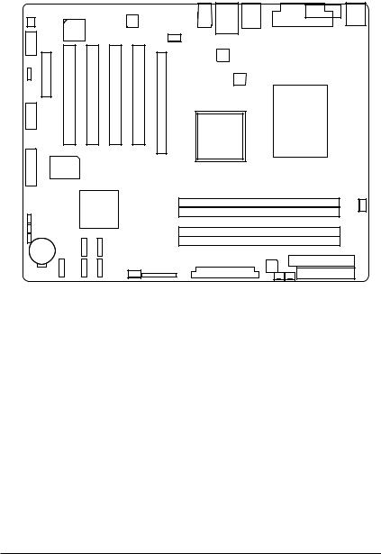
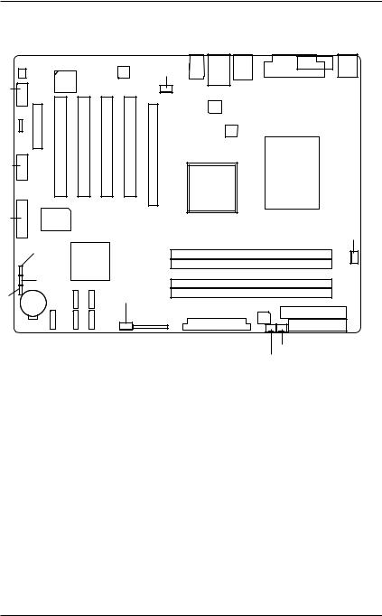
1.2 GA-5BXWL-RH Motherboard Components
1. |
CPU |
24. |
System fan cbale connector |
2. |
Intel X38 MCH |
25. |
Channel 1DDR1 socket |
3. |
Intel 82801IR ICH9 RAID |
26. |
Channel 2 DDR1 socket |
4. |
ITE IT8718F-S |
27. |
Channel 2 DDR2 socket |
5. |
IEEE 1394 controller |
28. |
Channel 2 DDR2 socket |
6. |
Broadcom BCM5786 |
29. |
PCI Express x4 slot |
7. |
Realtek ALC262 |
30. |
32bit/33MHz PCI slot #5 |
8. |
Case open intrusion connector |
31. |
32bit/33MHz PCI slot #4 |
9. |
IDE Connector |
32. |
32bit/33MHz PCI slot #3 |
10. |
Floppy Connector |
33. |
32bit/33MHz PCI slot #2 |
11. |
SATA1 cable connector |
34. |
PCI Express x16 slot |
12. |
SATA2 cable connector |
35. |
Keyboard Mouse port |
13. |
SATA3 cable connector |
36. |
COM port |
14. |
SATA4 cable connector |
37. |
Printer port |
15. |
SATA5 cable connector |
38. |
USB 2.0 port + IEEE1394 |
16. |
Internal Audio cable connector |
|
port |
17. |
Battery |
39. |
USB 2.0 port + Gigabit LAN |
18. |
Internal USB cable connector |
|
port |
19. |
Front USB and IEEE 1394 |
40. |
Audio port |
|
cable connectors |
41. |
24-pin ATX power connector |
20. |
CPU fan cable connector |
42. |
4-pin ATX power connector |
21. |
Front fan cable connector |
43. |
Front panel connector |
22.Rear fan cbale connector
23.Power supply fan cable connector
6
|
|
|
|
|
|
|
|
|
|
|
|
|
|
|
|
|
|
|
Introduction |
8 |
|
|
|
|
|
|
|
|
|
37 |
36 |
||||||||
|
|
|
|
|
|
7 |
|
|
|
40 |
39 |
38 |
|
|
|
|
|
||
|
|
|
|
|
|
|
|
|
|
|
|
|
|
|
35 |
||||
|
|
|
|
|
|
|
|
|
|
|
|
|
|
|
|||||
|
|
|
|
|
|
|
|
|
|
|
|
|
|
||||||
16 |
|
|
|
5 |
|
|
|
|
22 |
|
|
|
|
|
|
|
|
|
|
|
|
|
|
|
|
|
|
|
6 |
|
|
|
|
|
|
|
|
|
|
|
|
|
|
|
|
|
|
|
|
|
|
|
|
|
|
|
|
||
29 |
30 |
31 |
32 |
33 |
34 |
|
|
|
|
|
|
|
|
|
|||||
|
|
42 |
|
|
|
|
|
|
|
||||||||||
|
|
|
|
|
|
|
|
|
|
|
|
|
|
|
|
|
|
|
|
18 |
|
|
|
|
|
|
|
|
|
|
2 |
|
1 |
|
|
|
|||
|
|
|
|
|
|
|
|
|
|
|
|
|
|
||||||
|
|
|
|
|
|
|
|
|
|
|
|
|
|
|
|||||
|
|
|
|
|
|
|
|
|
|
|
|
|
|
|
|
|
|
|
|
19 |
|
|
|
4 |
|
|
|
|
|
25 |
|
|
|
|
|
|
20 |
||
|
|
|
|
|
|
|
|
|
|
|
|
|
|
||||||
|
|
|
|
|
|
|
|
|
|
|
|
|
|
|
|
||||
|
|
|
|
|
3 |
|
|
|
|
|
|
|
|
|
|
|
|
|
|
|
|
|
|
|
|
|
|
|
|
26 |
|
|
|
|
|
|
|
|
|
|
|
|
|
|
|
|
|
|
|
|
27 |
|
|
|
|
|
|
|
|
|
|
|
|
|
|
|
|
|
|
|
|
28 |
|
|
|
|
|
|
|
17 |
13 |
|
11 |
21 |
|
|
|
|
|
|
|
|
9 |
||||||
15 |
14 |
|
12 |
|
|
|
41 |
|
|
|
|
|
|||||||
|
|
|
|
|
|
|
|
|
|
10 |
|
|
|||||||
|
|
|
|
|
|
|
|
|
|
|
|
|
|
|
|
|
|
|
|
|
|
|
|
|
|
|
|
43 |
|
|
|
|
|
|
|
|
|
|
|
|
|
|
|
|
|
|
|
|
|
|
|
23 |
|
|
|
||||
|
|
|
|
|
|
|
|
|
|
|
|
|
24 |
|
|
|
|
|
|
7
GA-5BXWL-RH Motherboard
Chapter 2 Hardware Installation Process
2-1: Installing Processor and CPU Haet Sink
Before installing the processor and cooling fan, adhere to the following cautions:
1. The processor will overheat without the heatsink and/or fan, resulting in permanent irreparable damage.
2.Never force the processor into the socket.
3.Apply thermal grease on the processor before placing cooling fan.
4.Please make sure the CPU type is supported by the motherboard.
5.If you do not match the CPU socket Pin 1 and CPU cut edge well, it may damage the CPU. Please change the insert orientation.
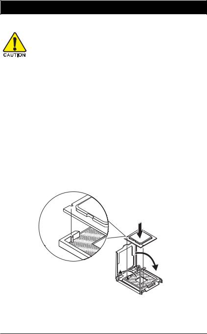
2-1-1: Installing CPU
Step 1 Raise the metal locking lever on the socket. Step 2 Remove the plastic covering on the CPU socket. Step 3 Lift the metal cover.
Step 4 Insert the CPU with the correct orientation. The CPU only fits in one orientation. Step 5 Once the CPU is properly placed, please replace the metal cover and push the metal
lever back into locked position.
8
Hardware Installation Process
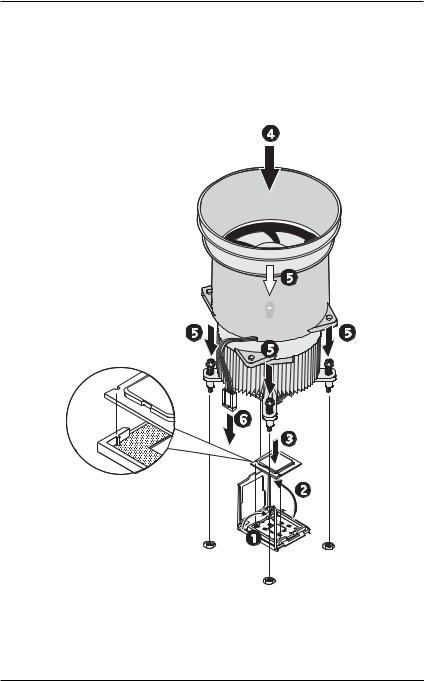
2-1-2: Installing Cooling Fan
Step 1 Attach the heat sink clip to the processor socket.
Step 2 Place the cooling fan on the heat sink.
Step 3 Secure the cooing fan with screws.
Step 4 Connect processor fan can cable to the processor fanconnector
9
GA-5BXWL-RH Motherboard
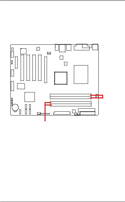
2-2: Install Memory Modules
GA-5BXWL-RH has 4 dual inline memory module (DIMM) sokcets. It supports Dual Channels Technology. The BIOS will automatically detects memory type and size during system boot. For detail DIMM installation, please refer to the following instructions.
Channel 1
Channel 2
1 0
Hardware Installation Process
Table 1. Supported DIMM Module Type
Size |
Organization |
RAM Chips/DIMM |
|
|
|
256MB |
8MB x 8 x 4 bks |
8 |
|
16MB x 4 x 4bks |
16 |
512MB |
16MB x 8 x 4bks |
8 |
|
32MB x 4 x 4bks |
16 |
1GB |
32MB x 8 x 4bks |
8 |
|
64MB x 4 x 4bks |
16 |
|
|
|
Installation Steps:
1.Unlock a DIMM socket by pressing the retaining clips outwards.Aling a DIMM on the socket such that the notch on the DIMM exactly match the notch in the socket.
2.Firmly insert the DIMMinto the socket until the retaining clips snap back in place.
NOTE!! We recommened you to populate the same device size on each socket and the same DIMM size.
4. Reverse the installation steps if you want to remove the DIMM module.
1 1

GA-5BXWL-RH Motherboard
2-3: Connect ribbon cables, cabinet wires, and power supply
2-3-1 : I/O Back Panel Introduction
1 2

Hardware Installation Process
 PS/2 Keyboard and PS/2 Mouse Connector
To install a PS/2 port keyboard and mouse, plug the mouse to the upper port (green) and the keyboard to the lower port (purple).
Parallel Port
The parallel port allows connection of a printer, scanner and other peripheral devices.
 COM Port
Modem can be connected to COM port.
 IEEE1394 Port
Serial interface standard set by Institute of Electrical and Electronics Engineers, which has features with high speed, high bandwidth and hot plug
USB Port
Before you connect your device(s) into USB connector(s), please make sure your device(s) such as USB keyboard, mouse, scanner, zip, speaker...etc. have a standard USB interface. Also make sure your OS supports USB controller. If your OS does not support USB controller, please contact OS vendor for possible patch or driver updated. For more information please contact your OS or device(s) vendors.
 LAN Port
The provided Internet connection is Gigabit Ethernet, providing data transfer speeds of 10/100/ 1000Mbps.
 Line In
The default Line In jack. Devices like CD-ROM, walkman etc. can be connected to Line In jack.
 Line Out (Front Speaker Out)
The default Line Out (Front Speaker Out) jack. Stereo speakers, earphone or front surround speakers can be connected to Line Out (Front Speaker Out) jack.
 MIC In
The default MIC In jack. Microphone must be connected to MIC In jack.
1 3
GA-5BXWL-RH Motherboard
2-4: Connectors Introduction & Jumper Setting
17
10 |
|
|
|
|
|
|
|
|
|
|
|
|
|
|
2 |
11 |
|
|
|
|
|
|
|
12 |
|
|
|
|
|
|
15 |
|
|
|
|
|
|
|
|
|
20 |
|
|
|
|
|
|
|
21 |
|
|
16 |
|
|
|
22 |
14 |
7 |
5 |
|
|
3 |
|
|
|
|
|||||
|
9 |
8 |
6 |
|
13 |
1 |
|
|
|
4 |
|||||
|
|
|
|
|
|
|
18 |
|
|
|
|
|
|
|
19 |
1. |
ATX1 |
|
|
|
|
13. |
F_PANEL1 |
2. |
ATX_12V |
|
|
|
|
14. |
BAT1 (Battery) |
3. |
IDE1 (IDE cable connector) |
|
15. |
CPU_FAN |
|||
4. |
FDD (Floppy cable connector) |
16. |
FRONT_FAN |
||||
5. |
S_ATA1 (SATA cable connector) |
17. |
REAR_FAN |
||||
6. |
S_ATA2 (SATA cable connector) |
18. |
PSU_FAN |
||||
7. |
S_ATA3 (SATA cable connector) |
19. |
SYS_FAN |
||||
8. |
S_ATA4 (SATA cable connector) |
20. |
JP2 |
||||
9. |
S_ATA5 (SATA cable connector) |
21 |
JP3 |
||||
10. |
FAUDIO_ACZ |
|
|
|
22.. JP1 |
||
11.F_USB2 (Internal USB cable connector)
12.F_USB1+1394 (Front 1394 cable connector)
1 4
 Loading...