


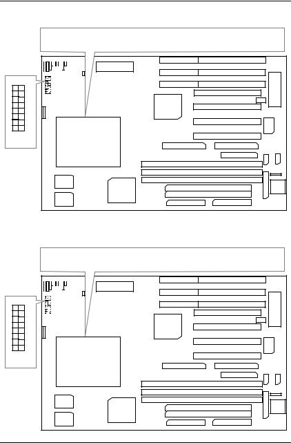
GA - 586TX3
USER'S MANUAL
¯Auto detect CPU Voltage.
¯Support MMX CPU.
¯Auto CPU Over heat Protect System (A.C.O.P.S.)
¯Switching mode Voltage regulator on Board.
¯Modem-Ring-On.
¯Support Cyrix / IBM 6x86MX & AMD-K6 CPU.
¯In CASE you want to Power OFF System Before Boot up please press Soft-Power more than 4- Secs.
¯FOR 5V CMOS ISA CARD, PLS insert in Slot5.
+ |
CPU |
¯ J8¡ ATXG POWER USE only.
¯ J8¡ ONG |
System After AC BACK¡ FullG _ON. |
¯ J8¡ OFFG |
System After AC BACK¡ SoftG _OFF. |
Pentium â Processor PCI - ISA BUS MAINBOARD
REV. 1.0 Second Edition
Release Date 97.05.20

GA-586TX3
I.Quick Installation Guide:
|
CPU |
SW1 |
SW2 |
SW3 |
SW4 |
SW5 |
SW6 |
SW7 |
SW8 |
|
|
|
|
|
|
|
|
|
|
|
|
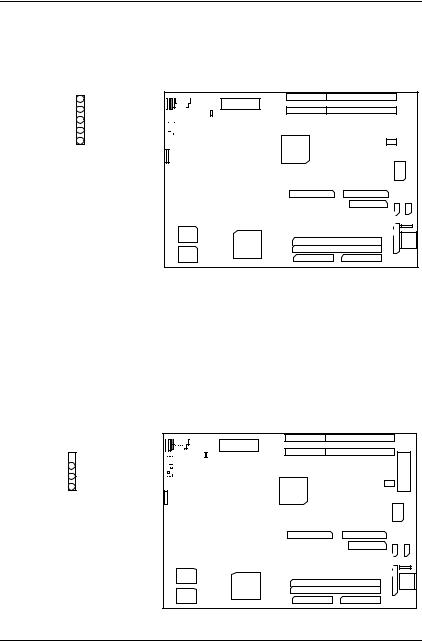
1. |
Pentiumâ Processor 90 MHz |
ON |
OFF |
OFF |
OFF |
OFF |
OFF |
ON |
OFF |
|
|
|
|
|
|
|
|
|
|
|
|
2. |
Pentiumâ Processor 100 MHz |
OFF |
OFF |
OFF |
OFF |
OFF |
OFF |
ON |
OFF |
|
|
|
|
|
|
|
|
|
|
|
|
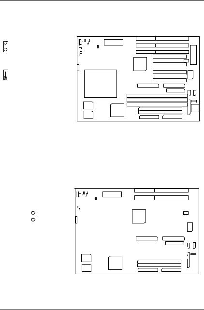
3. |
Pentiumâ Processor 120 MHz |
ON |
ON |
OFF |
OFF |
OFF |
OFF |
ON |
OFF |
|
|
|
|
|
|
|
|
|
|
|
|
4. |
Pentiumâ Processor 133 MHz |
OFF |
ON |
OFF |
OFF |
OFF |
OFF |
ON |
OFF |
|
|
|
|
|
|
|
|
|
|
|
|
5. |
Pentiumâ Processor 150 MHz |
ON |
ON |
ON |
OFF |
OFF |
OFF |
ON |
OFF |
|
|
|
|
|
|
|
|
|
|
|
|
6. |
Pentiumâ Processor 166 MHz |
OFF |
ON |
ON |
OFF |
OFF |
OFF |
ON |
OFF |
|
|
|
|
|
|
|
|
|
|
|
|
7. |
Pentiumâ Processor 180 MHz |
ON |
OFF |
ON |
OFF |
OFF |
OFF |
ON |
OFF |
|
|
|
|
|
|
|
|
|
|
|
|
8. |
Pentiumâ Processor 200 MHz |
OFF |
OFF |
ON |
OFF |
OFF |
OFF |
ON |
OFF |
|
|
|
|
|
|
|
|
|
|
|
|
9. |
Intel MMX-150MHz |
ON |
ON |
ON |
OFF |
OFF |
OFF |
ON |
OFF |
|
|
|
|
|
|
|
|
|
|
||
10. Intel MMX-166MHz |
OFF |
ON |
ON |
OFF |
OFF |
OFF |
ON |
OFF |
||
|
|
|
|
|
|
|
|
|
||
11. Intel MMX-200MHz |
OFF |
OFF |
ON |
OFF |
OFF |
OFF |
ON |
OFF |
||
|
|
|
|
|
|
|
|
|
||
12. Intel MMX-233MHz |
OFF |
OFF |
OFF |
OFF |
OFF |
OFF |
ON |
OFF |
||
|
|
|
|
|
|
|
|
|
||
13. P54CT-150 MHz |
ON |
ON |
ON |
OFF |
OFF |
OFF |
ON |
OFF |
||
|
|
|
|
|
|
|
|
|
||
14. P54CT-166 MHz |
OFF |
ON |
ON |
OFF |
OFF |
OFF |
ON |
OFF |
||
|
|
|
|
|
|
|
|
|
|
|
15. |
P54CTB-150 MHz |
ON |
ON |
ON |
OFF |
OFF |
OFF |
ON |
OFF |
|
|
|
|
|
|
|
|
|
|
|
|
16. |
P54CTB-166 MHz |
OFF |
ON |
ON |
OFF |
OFF |
OFF |
ON |
OFF |
|
|
|
|
|
|
|
|
|
|
|
|
|
|
|
|
|
|
|
|
|
|
|
|
|
2 |
|
|
|
|
|
|
|
|

Table of Contents
|
AMD/Cyrix CPU |
SW1 |
SW2 |
SW3 |
SW4 |
SW5 |
SW6 |
SW7 |
SW8 |
||
|
|
|
|
|
|
|
|
|
|
||
17. |
P54CTB-180 MHz |
ON |
OFF |
ON |
OFF |
OFF |
OFF |
ON |
OFF |
||
|
|
|
|
|
|
|
|
|
|
||
18. |
P54CTB-200 MHz |
OFF |
OFF |
ON |
OFF |
OFF |
OFF |
ON |
OFF |
||
|
|
|
|
|
|
|
|
|
|
||
19. |
AMDK5-PR133 |
OFF |
ON |
OFF |
OFF |
OFF |
OFF |
ON |
OFF |
||
|
|
|
|
|
|
|
|
|
|
||
20. |
AMDK5-PR166 |
OFF |
ON |
ON |
OFF |
OFF |
OFF |
ON |
OFF |
||
|
|
|
|
|
|
|
|
|
|
|
|
21. |
AMD-K6 |
/ 166 |
(2.9V) |
OFF |
ON |
ON |
OFF |
OFF |
ON |
ON |
OFF |
|
|
|
|
|
|
|
|
|
|
|
|
22. |
AMD-K6 |
/ 180 |
(2.9V) |
ON |
OFF |
ON |
OFF |
OFF |
ON |
ON |
OFF |
|
|
|
|
|
|
|
|
|
|
|
|
23. .AMD-K6 |
/ 200 |
(2.9V) |
OFF |
OFF |
ON |
OFF |
OFF |
ON |
ON |
OFF |
|
|
|
|
|
|
|
|
|
|
|
|
|
24. |
AMD-K6 |
/ 233 |
(3.2V) |
OFF |
OFF |
OFF |
ON |
OFF |
OFF |
ON |
OFF |
|
|
|
|
|
|
|
|
|
|||
25. Cyrix/ IBM 6x86-120 MHz-PR150+ |
ON |
ON |
OFF |
OFF |
OFF |
OFF |
ON |
OFF |
|||
|
|
|
|
|
|
|
|
|
|||
26. Cyrix/ IBM 6x86-133 MHz-PR166+ |
OFF |
ON |
OFF |
OFF |
OFF |
OFF |
ON |
OFF |
|||
|
|
|
|
|
|
|
|
|
|||
27. Cyrix/ IBM 6x86LPR150+ (2.8V) |
ON |
ON |
OFF |
OFF |
OFF |
OFF |
ON |
OFF |
|||
|
|
|
|
|
|
|
|
|
|||
28. Cyrix/ IBM 6x86L-PR166+ (2.8V) |
OFF |
ON |
OFF |
OFF |
OFF |
OFF |
ON |
OFF |
|||
|
|
|
|
|
|
|
|
|
|||
29. Cyrix/IBM 6x86MX-PR166GP(2.9V) |
ON |
ON |
ON |
OFF |
OFF |
ON |
ON |
OFF |
|||
|
|
|
|
|
|
|
|
|
|||
30. Cyrix/IBM 6x86MX-PR200GP(2.9V) |
OFF |
ON |
ON |
OFF |
OFF |
ON |
ON |
OFF |
|||
|
|
|
|
|
|
|
|
|
|||
31. Cyrix/IBM 6x86MX-PR233GP(2.9V) |
OFF |
OFF |
ON |
OFF |
OFF |
ON |
ON |
OFF |
|||
|
|
|
|
|
|
|
|
|
|
|
|
¬Note : If Cyrix 6x86 is being used, please check the CPU Date Code after 605.
¬Note : Cyrix/IBM 6x86MX-PR166GP (60*2.5) , Cyrix/IBM 6x86MX-PR200GP (66*2.5) ,
Cyrix/IBM 6x86MX-PR233GP (66*3) .
3

GA-586TX3
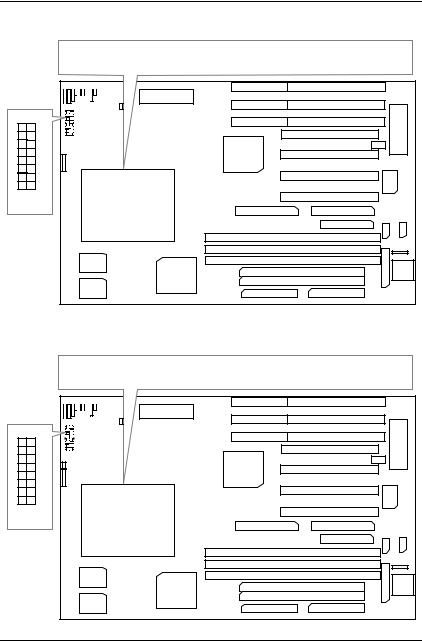
1. Pentiumâ Processor 90 MHz
Pentium R Processor 90 MHz
+ |
 8
8
 7
7
 6
6
 5
5
 4
4
 3
3
 2
2
 1
1
ON OFF
CPU
2. Pentiumâ Processor 100 MHz
Pentium R Processor 100 MHz
+ |
 8
8
 7
7
 6
6
 5
5
 4
4
 3
3
 2
2
 1
1
ON OFF
CPU
4
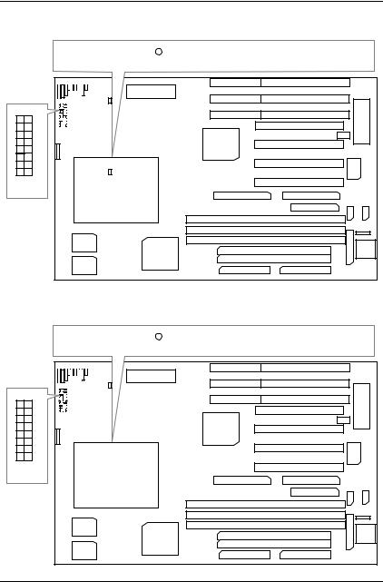
Table of Contents
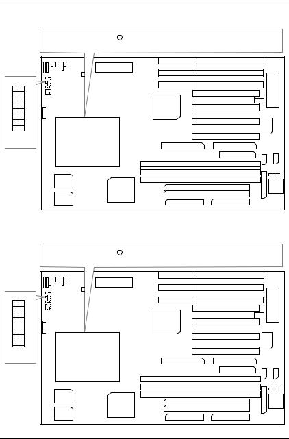
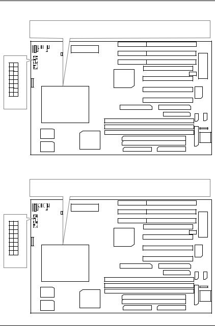
3. Pentiumâ Processor 120 MHz
Pentium R Processor 120 MHz
+ |
 8
8
 7
7
 6
6
 5
5
 4
4
 3
3
 2
2
 1
1
ON OFF
CPU
4. Pentiumâ Processor 133 MHz
Pentium R Processor 133 MHz
+ |
 8
8
 7
7
 6
6
 5
5
 4
4
 3
3
 2
2
 1
1
ON OFF
CPU
5
GA-586TX3
5. Pentiumâ Processor 150 MHz
Pentium R Processor 150 MHz
+ |
 8
8
 7
7
 6
6
 5
5
 4
4
 3
3
 2
2
 1
1
ON OFF
CPU
6. Pentiumâ Processor 166 MHz
Pentium R Processor 166 MHz
+ |
 8
8
 7
7
 6
6
 5
5
 4
4
 3
3
 2
2
 1
1
ON OFF
CPU
6
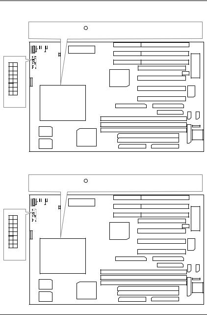
Table of Contents
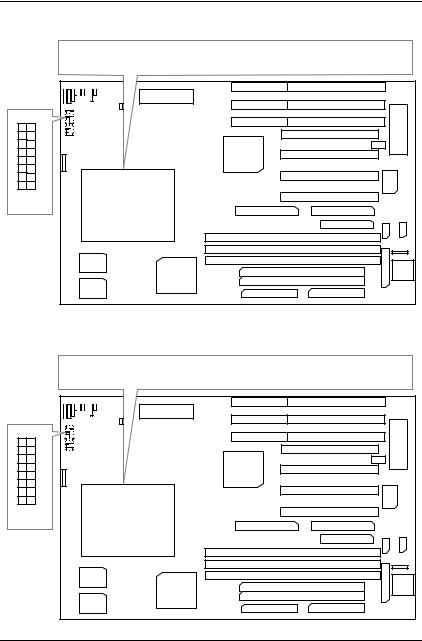
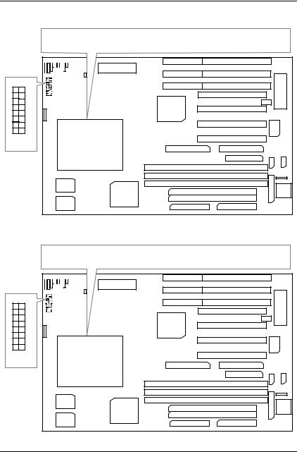
7. Pentiumâ Processor 180 MHz
Pentium R Processor 180 MHz
+ |
 8
8
 7
7
 6
6
 5
5
 4
4
 3
3
 2
2
 1
1
ON OFF
CPU
8. Pentiumâ Processor 200 MHz
Pentium R Processor 200 MHz
+ |
 8
8
 7
7
 6
6
 5
5
 4
4
 3
3
 2
2
 1
1
ON OFF
CPU
7
GA-586TX3
9. Intel MMX-150 MHz
Intel MMX-150MHz
+ |
 8
8
 7
7
 6
6
 5
5
 4
4
 3
3
 2
2
 1
1
ON OFF
CPU
10. Intel MMX-166 MHz
Intel MMX-166 MHz
+ |
 8
8
 7
7
 6
6
 5
5
 4
4
 3
3
 2
2
 1
1
ON OFF
CPU
8

Table of Contents
11. Intel MMX-200 MHz
Intel MMX-200 MHz
+ |
 8
8
 7
7
 6
6
 5
5
 4
4
 3
3
 2
2
 1
1
ON OFF
CPU
12. Intel MMX-233 MHz
Intel MMX-233 MHz
+ |
 8
8
 7
7
 6
6
 5
5
 4
4
 3
3
 2
2
 1
1
ON OFF
CPU
9
GA-586TX3
13. P54CT-150 MHz
P54CT-150 MHz
+ |
 8
8
 7
7
 6
6
 5
5
 4
4
 3
3
 2
2
 1
1
ON OFF
CPU
14. P54CT-166 MHz
P54CT-166 MHz
+ |
 8
8
 7
7
 6
6
 5
5
 4
4
 3
3
 2
2
 1
1
ON OFF
CPU
10
Table of Contents
15. P54CTB-150 MHz
P54CTB-150 MHz
+ |
 8
8
 7
7
 6
6
 5
5
 4
4
 3
3
 2
2
 1
1
ON OFF
CPU
16. P54CTB-166 MHz
P54CTB-166 MHz
+ |
 8
8
 7
7
 6
6
 5
5
 4
4
 3
3
 2
2
 1
1
ON OFF
CPU
11

GA-586TX3
17. P54CTB-180 MHz
P54CTB-180 MHz
+ |
 8
8
 7
7
 6
6
 5
5
 4
4
 3
3
 2
2
 1
1
ON OFF
CPU
18. P54CTB-200 MHz
P54CTB-200 MHz
+ |
 8
8
 7
7
 6
6
 5
5
 4
4
 3
3
 2
2
 1
1
ON OFF
CPU
12

Table of Contents
19. AMDK5-PR133
AMDK5-PR133
+ |
 8
8
 7
7
 6
6
 5
5
 4
4
 3
3
 2
2
 1
1
ON OFF
CPU
20. AMDK5-PR166
AMDK5-PR166
+ |
 8
8
 7
7
 6
6
 5
5
 4
4
 3
3
 2
2
 1
1
ON OFF
CPU
13
GA-586TX3
21. AMD-K6/166 (2.9V)
AMD-K6/166 (2.9V)
+ |
 8
8
 7
7
 6
6
 5
5
 4
4
 3
3
 2
2
 1
1
ON OFF
CPU
22. AMD-K6/180 (2.9V)
AMD-K6/180 (2.9V)
+ |
 8
8
 7
7
 6
6
 5
5
 4
4
 3
3
 2
2
 1
1
ON OFF
CPU
14
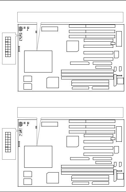
Table of Contents
23. AMD-K6/200 (2.9V)
AMD-K6/200 (2.9V)
+ |
 8
8
 7
7
 6
6
 5
5
 4
4
 3
3
 2
2
 1
1
ON OFF
CPU
24. AMD-K6/233 (3.2V)
AMD-K6/233 (3.2V)
+ |
 8
8
 7
7
 6
6
 5
5
 4
4
 3
3
 2
2
 1
1
ON OFF
CPU
15
GA-586TX3
25. Cyrix / IBM 6x86-120 MHz-PR150+
Cyrix / IBM 6x86-120 MHz-PR150+
+ |
 8
8
 7
7
 6
6
 5
5
 4
4
 3
3
 2
2
 1
1
ON OFF
CPU
26. Cyrix /IBM 6x86-133 MHz-PR166+
Cyrix / IBM 6x86-133 MHz-PR166+
+ |
 8
8
 7
7
 6
6
 5
5
 4
4
 3
3
 2
2
 1
1
ON OFF
CPU
16

Table of Contents
27. Cyrix / IBM 6x86L-PR150+ (2.8V)
Cyrix / IBM 6x86L-PR150+ (2.8V)
+ |
 8
8
 7
7
 6
6
 5
5
 4
4
 3
3
 2
2
 1
1
ON OFF
CPU
28. Cyrix / IBM 6x86L-PR166+ (2.8V)
Cyrix / IBM 6x86L-PR166+ (2.8V)
+ |
 8
8
 7
7
 6
6
 5
5
 4
4
 3
3
 2
2
 1
1
ON OFF
CPU
17
GA-586TX3
29. Cyrix / IBM 6x86MX-PR166GP (60x2.5 2.9V)
Cyrix / IBM 6x86MX-PR166GP (60x2.5 2.9V)
+ |
 8
8
 7
7
 6
6
 5
5
 4
4
 3
3
 2
2
 1
1
ON OFF
CPU
30. Cyrix / IBM 6x86MX-PR200GP (66x2.5 2.9V)
Cyrix / IBM 6x86MX-PR200GP (66x2.5 2.9V)
+ |
 8
8
 7
7
 6
6
 5
5
 4
4
 3
3
 2
2
 1
1
ON OFF
CPU
18
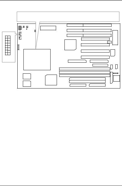
Table of Contents
31. Cyrix / IBM 6x86MX-PR233GP (66x3 2.9V)
Cyrix / IBM 6x86MX-PR233GP (66x3 2.9V)
+ |
 8
8
 7
7
 6
6
 5
5
 4
4
 3
3
 2
2
 1
1
ON OFF
CPU
19
GA-586TX3
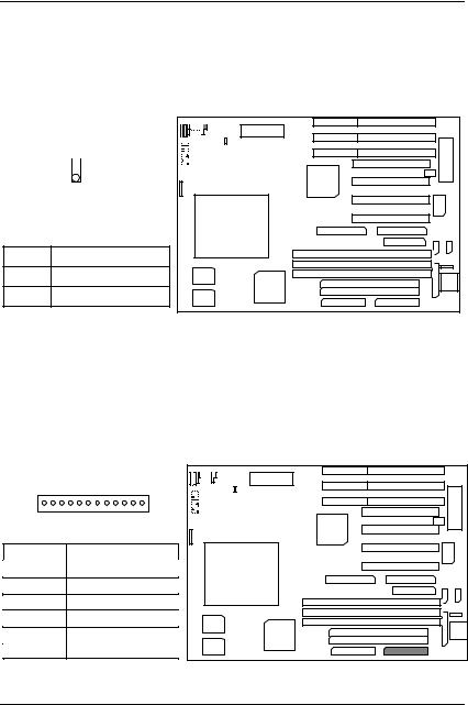
II. Quick Installation Guide of Jumper setting:
PWR : Power / Key-Lock Connector
1 |
1 |
|
+ |
||
|
|
|
|
|
|
|
|
|
|
|
|
|
|
|
|
|
|
|
|
|
|
|
|
|
|
|
|
|
|
|
|
|
|
|
|
|
|
|
|
|
|
|
|
|
|
|
|
|
|
|
|
|
|
|
|
|
|
|
|
|
|
|
|
|
|
|
|
|
|
Pin No. |
Function |
|
|
|
|
|
|
|
|
|
|
|
|
|
|
|
|
|
|
|
|
|
|
|
|
|
|
|
|
|
|
|
|
|
|
|
|
|
|
|
|
|
|
||
|
|
|
|
|
|
|
|
|
|
|
|
|
|
|
|
|
|
|
|
|
|
|
1 |
LED anode (+) |
|
|
|
|
|
CPU |
|
|
|
|
|
|
|
|
|
|
|
|
|
||
|
|
|
|
|
|
|
|
|
|
|
|
|
|
|
|
|
|
|||||
|
|
|
|
|
|
|
|
|
|
|
|
|
|
|
|
|
|
|||||
|
|
|
|
|
|
|
|
|
|
|
|
|
|
|
|
|
|
|
|
|||
2 |
NC |
|
|
|
|
|
|
|
|
|
|
|
|
|
||||||||
|
|
|
|
|
|
|
|
|
|
|
|
|
|
|
|
|
|
|
|
|
||
|
|
|
|
|
|
|
|
|
|
|
|
|
|
|
|
|
|
|
|
|
|
|
3 |
LED cathode (-) |
|
|
|
|
|
|
|
|
|
|
|
|
|
|
|
|
|
|
|
|
|
|
|
|
|
|
|
|
|
|
|
|
|
|
|
|
|
|
|
|
|
|
||
|
|
|
|
|
|
|
|
|
|
|
|
|
|
|
|
|
|
|
|
|
|
|
4 |
Key Lock |
|
|
|
|
|
|
|
|
|
|
|
|
|
|
|
|
|
|
|
|
|
|
|
|
|
|
|
|
|
|
|
|
|
|
|
|
|
|
|
|
|
|
|
|
5 |
GND |
|
|
|
|
|
|
|
|
|
|
|
|
|
|
|
|
|
|
|
|
|
|
|
|
|
|
|
|
|
|
|
|
|
|
|
|
|
|
|
|
|
|
|
|
]1. Power LED will be flashed twice per second when system Get into Green mode on CPU temperature over Limit.
2.Power LED will be flashed once per second when system Get into Soft-off mode (ATX PWR only).
SPK : Speaker Connector
1 |
+ |
1 
|
|
|
|
|
|
|
|
|
|
|
|
|
|
|
|
|
|
|
|
|
|
|
|
|
|
|
|
|
|
|
|
|
|
|
|
|
|
|
|
|
|
|
|
|
|
|
|
|
|
|
|
|
|
|
|
|
|
|
|
|
|
|
|
|
|
|
|
|
|
|
|
|
|
|
|
|
|
|
|
|
|
|
|
|
|
|
|
|
|
|
|
|
|
|
|
|
|
|
|
|
|
|
|
|
|
|
|
|
|
|
|
|
|
|
|
|
|
|
|
|
|
|
|
|
|
|
|
Pin No. |
Function |
|
|
|
CPU |
|
|
|
|
|
|
|
|
|
|
|
|
|
|
|
|
|
|
|
|
|
|
|
|
||
|
|
|
|
|
|
|
|
|
|
|
|
|
|
|
|
1 |
VCC |
|
|
|
|
|
|
|
|
|
|
||||
|
|
|
|
|
|
|
|
|
|
|
|
|
|
||
|
|
|
|
|
|
|
|
|
|
|
|
|
|
|
|
2 |
NC |
|
|
|
|
|
|
|
|
|
|
|
|
|
|
|
|
|
|
|
|
|
|
|
|
|
|
|
|
||
|
|
|
|
|
|
|
|
|
|
|
|
|
|
|
|
3 |
NC |
|
|
|
|
|
|
|
|
|
|
|
|
|
|
|
|
|
|
|
|
|
|
|
|
|
|
|
|
|
|
4 |
Data |
|
|
|
|
|
|
|
|
|
|
|
|
|
|
|
|
|
|
|
|
|
|
|
|
|
|
|
|
||
|
|
|
|
|
|
|
|
|
|
|
|
|
|
|
|
20
Table of Contents
TD : Turbo LED Connector
1
+ |
1
|
|
|
|
|
|
|
|
|
|
|
|
|
|
|
|
|
|
|
|
|
|
|
|
|
|
|
|
|
|
|
|
|
|
|
|
|
|
|
|
|
|
|
|
|
|
|
|
|
|
|
|
|
|
|
|
|
|
|
|
|
|
|
|
|
|
|
|
|
|
|
|
|
|
|
|
|
|
|
|
|
|
|
|
|
|
|
|
|
|
|
|
|
|
|
|
|
|
|
|
|
|
|
|
|
|
|
|
|
|
|
|
|
|
|
|
|
|
|
|
|
|
|
|
|
|
|
|
|
|
|
|
|
|
|
|
|
|
|
|
|
|
|
|
Pin No. |
Function |
|
|
|
CPU |
|
|
|
|
|
|
|
|
|
|
|
|
1 |
LED anode (+) |
|
|
|
|
|
|
|
|
|
|
|
|
|
|
|
|
|
|
|
|
|
|
|
|
|
|
|
|
|
|
|
|
|
|
2 |
LED cathode (-) |
|
|
|
|
|
|
|
|
|
|
|
|
|
|
|
|
|
|
|
|
|
|
|
|
|
|
|
|
|
|
|
|
|
|
|
|
|
|
|
|
|
|
|
|
|
|
|
|
|
|
|
|
TB : Turbo Switch Connector
1
+ |
Function Reserved.
CPU
21
GA-586TX3
RST : Reset Switch
1
+
1
Open :
Normal operation.
1 
Close : |
|
For hardware reset system. |
CPU |
GD : Green Function LED
1
+ |
|
1 |
|
|
|
|
|
|
|
|
|
|
|
|
|
|
|
|
|
|
|
|
|
|
|
|
|
|
|
|
|
|
|
|
|
|
|
|
|
|
|
|
|
|
|
|
|
|
|
|
|
|
|
|
|
|
|
|
|
|
|
|
|
|
|
|
|
|
|
|
|
|
|
|
|
|
|
|
|
|
|
|
|
|
|
|
|
|
|
|
|
|
|
|
|
|
|
|
|
|
|
|
|
|
|
|
|
|
|
CPU |
|
|
|
|
|
|
|
|
|
|
|
|
|
||
|
|
|
|
|
|
|
|
|
|
|
|
|
|
|
|
|
|
|
|
|
|
|||
|
|
|
|
|
|
|
|
|
|
|
|
|
|
|
|
|
|
|
|
|
|
|||
|
|
|
|
|
|
|
|
|
|
|
|
|
|
|
|
|
|
|
|
|
|
|||
Pin No. |
|
Function |
|
|
|
|
|
|
|
|
|
|
|
|
|
|
|
|
|
|
|
|
|
|
1 |
LED anode (+) |
|
|
|
|
|
|
|
|
|
|
|
|
|
|
|
|
|
|
|
|
|
||
|
|
|
|
|
|
|
|
|
|
|
|
|
|
|
|
|
|
|
|
|
||||
|
|
|
|
|
|
|
|
|
|
|
|
|
|
|
|
|
|
|
|
|
||||
2 |
LED cathode (-) |
|
|
|
|
|
|
|
|
|
|
|
|
|
|
|
|
|
|
|
|
|
||
|
|
|
|
|
|
|
|
|
|
|
|
|
|
|
|
|
|
|
|
|
||||
|
|
|
|
|
|
|
|
|
|
|
|
|
|
|
|
|
|
|
|
|
|
|
|
|
22
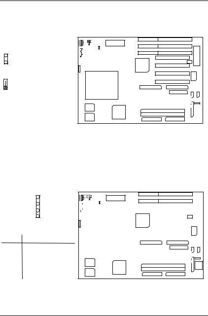
Table of Contents
GN : Green Function Switch
1
+ |
1
Open :
Normal operation.
1 
Close One Time : |
CPU |
|
|
||||
|
|
|
|||||
For system entering Green |
|
|
|
|
|
|
|
|
|
|
|
|
|
|
|
|
|
|
|
|
|
|
|
|
|
|
|
|
|
|
|
HD : IDE Hard Disk Active LED
|
1 |
1 |
+ |
|
|
|
|
|
|
|
|
|
|
|
|
|
|
|
|
|
|
|
|
|
|
|
|
|
|
|
|
|
|
|
|
|
|
|
|
|
|
|
|
|
|
|
|
|
|
|
|
|
|
|
|
|
|
|
|
|
|
|
|
|
|
|
|
|
|
|
|
|
|
|
|
|
|
|
|
|
|
|
|
|
|
|
|
|
|
|
|
|
|
|
|
|
|
|
|
|
|
|
|
|
|
|
|
|
|
|
|
|
|
|
|
|
|
|
|
|
|
|
|
|
|
|
|
|
Pin No. |
Function |
|
|
|
|
|
CPU |
|
|
|
|
|
|
|
|
|
|
|
|
|
|
|
||
|
|
|
|
|
|
|
|
|
|
|
|
|
|
|
|
|
|
|
|
|||||
1 |
LED anode (+) |
|
|
|
|
|
|
|
|
|
|
|
|
|
|
|
|
|
|
|
|
|||
|
|
|
|
|
|
|
|
|
|
|
|
|
|
|
|
|
|
|
|
|
|
|
||
2 |
LED cathode (-) |
|
|
|
|
|
|
|
|
|
|
|
|
|
|
|
|
|
|
|
|
|
|
|
|
|
|
|
|
|
|
|
|
|
|
|
|
|
|
|
|
|
|
|
|
|
|
|
|
3 |
LED cathode (-) |
|
|
|
|
|
|
|
|
|
|
|
|
|
|
|
|
|
|
|
|
|
|
|
|
|
|
|
|
|
|
|
|
|
|
|
|
|
|
|
|
|
|
|
|
|
|
|
|
4 |
LED anode (+) |
|
|
|
|
|
|
|
|
|
|
|
|
|
|
|
|
|
|
|
|
|
|
|
23
GA-586TX3
Soft Power Connector
1
+ |
1 
CPU
Pin No. |
Function |
1 GND
2 CTRL-Signal
PW1 : Power Connector |
|
||
|
|
+ |
|
|
1 |
|
|
Pin No. |
Function |
|
|
1 |
Power Good signal |
CPU |
|
2,10,11,12 |
VCC (+5V) |
||
|
|||
3 |
+12V |
|
|
4 |
-12V |
|
|
5,6,7,8 |
GND |
|
|
9 |
-5V |
1 |
|
|
|||
|
|
24 |
|
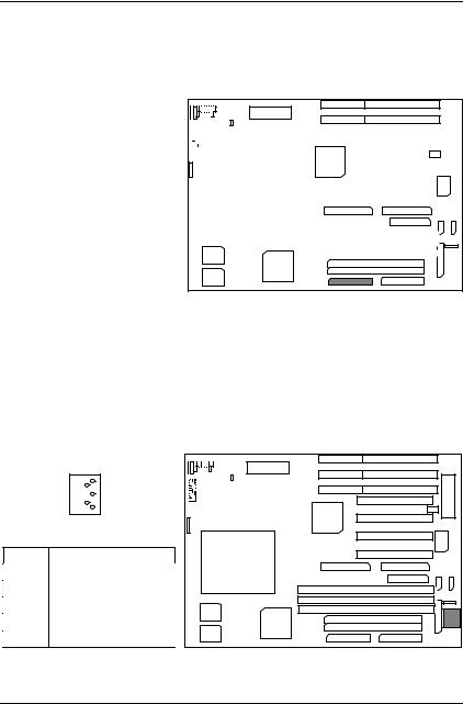
Table of Contents
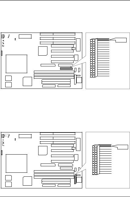
Power1: ATX POWER Connector
+ |
|
|
|
|
|
|
|
|
|
|
|
|
|
|
|
|
|
|
|
|
|
|
|
Pin No. |
Function |
|
|
|
|
|
|
|
|
|
|
|
|
|
|
|
|
|
|
|
|
|
3,5,7,13,15-17 |
GND |
|
|
|
|
|
|
|
|
|
|
|
|
|
|
|
|
|
|
|
|
|
|
|
|
|
|
|
|
|
|
|
|
|
|
|
|
|
|
|
|
|
|
|
|
4,6,19,20 |
VCC (+5V) |
|
|
|
|
|
|
|
|
|
|
|
|
|
|
|
|
|
|
|
|
|
|
|
|
|
|
|
|
|
|
|
|
|
|
|
|
|
|
|
|
|
|
||
|
|
|
|
|
|
|
|
|
|
|
|
|
|
|
|
|
|
|
|
|
||
10 |
+12V |
|
|
|
|
|
CPU |
|
|
|
|
|
|
|
|
|
|
|
|
|
||
|
|
|
|
|
|
|
|
|
|
|
|
|
|
|
|
|
|
|||||
|
|
|
|
|
|
|
|
|
|
|
|
|
|
|
|
|
|
|||||
12 |
-12V |
|
|
|
|
|
|
|
|
|
|
|
|
|
|
|
|
|
|
|||
|
|
|
|
|
|
|
|
|
|
|
|
|
|
|
|
|
|
|
|
|
||
18 |
-5V |
|
|
|
|
|
|
|
|
|
|
|
|
|
|
|
|
|
|
|
|
|
|
|
|
|
|
|
|
|
|
|
|
|
|
|
|
|
|
|
|
|
|
||
|
|
|
|
|
|
|
|
|
|
|
|
|
|
|
|
|
|
|
|
|
|
|
8 |
Power Good |
|
|
|
|
|
|
|
|
|
|
|
|
|
|
|
|
|
|
|
|
|
9 |
5V SB (Stand by +5V) |
|
|
|
|
|
|
|
|
|
|
|
|
|
|
|
|
|
|
|
|
|
|
|
1 |
|
|
|
|
|
|
|
|
|
|||||||||||
14 |
PS-ON (Soft ON/OFF) |
|
|
|
|
|
|
|
|
|
||||||||||||
|
|
|
|
|
|
|
|
|
|
|
|
|
|
|
|
|
|
|
|
|
||
|
|
|
|
|
|
|
|
|
|
|
|
|
|
|
|
|
|
|
|
|
|
|
J1 : Keyboard Connector
|
|
+ |
|
1 |
|
|
2 |
|
|
3 |
|
|
4 |
|
|
5 |
|
Pin No. |
Function |
CPU |
1 |
Key Clock. |
|
2 |
Key Data |
|
3 |
NC |
|
4 |
VCC (+5V) |
|
5 |
GND |
|
|
|
25 |
GA-586TX3
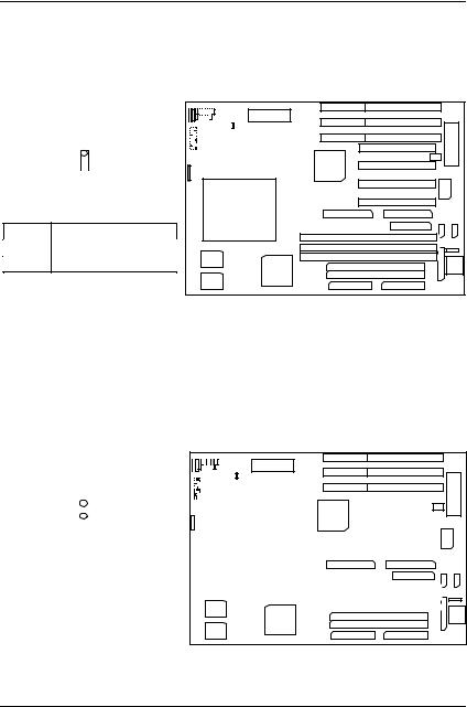
J6: CPU Cooling Fan Power Connector
+ |
1 
1
CPU
Pin No. |
Function |
1+12V
2GND
J8 : ATX POWER USE Only
+ |
1
|
1 |
|
|
|
|
|
|
|
|
|
|
|
|
|
|
|
|
|
|
|
|
|
|
|
|
|
|
|
|
|
|
|
|
|
|
|
|
|
|
|
|
|
|
|
|
|
|
|
|
|
|
|
|
|
|
|
|
|
|
|
|
|
|
|
|
|
|
|
|
|
|
|
|
|
|
|
|
|
|
|
|
|
|
|
|
|
CPU |
|
|
|
|
|
|
|
|
|
|
|
|
|
|
|
|
|
|
|
|
|
|
|
|
|
|
|
|
|
|
|
|
|
|
|
|
|
|
|
|
|
|
|
|
|
|
|
|
|
|
|
|
|
|
|
|
Pin No. |
|
Function |
|
|
|
|
|
|
|
|
|||||
|
|
|
|
|
|
|
|
|
|
|
|
|
|||
ON |
System After AC BACK: |
|
|
|
|
|
|
|
|
|
|
|
|
||
|
|
|
|
|
|
|
|
|
|
|
|
||||
|
|
|
|
|
|
|
|
|
|
|
|
||||
|
Full_ON. |
|
|
|
|
|
|
|
|
|
|
|
|
||
|
|
|
|
|
|
|
|
|
|
|
|
|
|||
OFF |
System After AC BACK: |
|
|
|
|
|
|
|
|
|
|
|
|
||
Soft_OFF. |
|
|
|
|
|
|
|
|
|
|
|
|
|||
|
|
|
|
|
|
|
|
|
|
|
|
|
|||
26
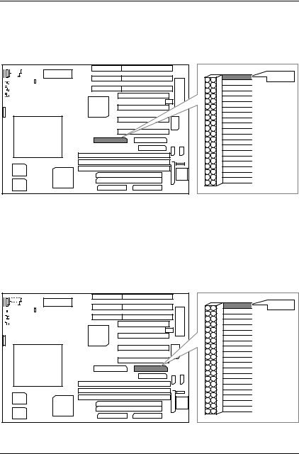
Table of Contents
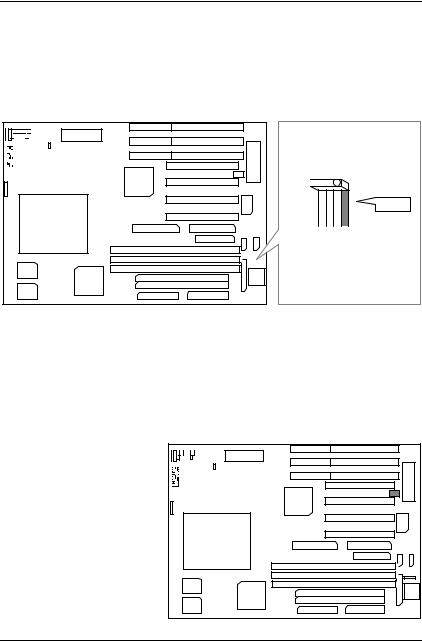
J4 : For Primary IDE port
+ |
RED LINE |
|
|
|
1 |
CPU |
1 |
J3 : For Secondary IDE port |
|
+ |
RED LINE |
|
|
|
1 |
CPU |
1 |
|
|
|
27 |
GA-586TX3
CN4 : FLOPPY PORT
+ |
|
1 |
RED LINE |
CPU |
|
1 |
|
CN1 : LPT PORT |
|
+ |
|
1 |
RED LINE |
CPU |
|
1 |
|
28 |
|
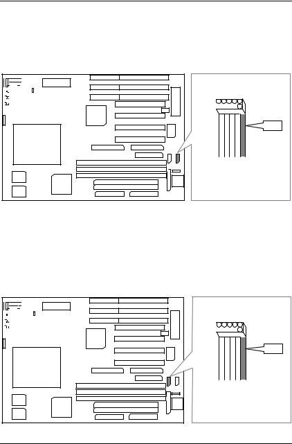
Table of Contents
CN2 : COM B
+


 1
1
RED LINE
CPU
1
CN3 : COM A
+


 1
1
RED LINE
CPU
1
29
GA-586TX3
J2 : PS/2 MOUSE
+


 1
1
RED LINE
CPU

 1
1
JP1: USB Port
Pin No. |
Function |
1 |
SBV0 |
2 |
SBD0- |
|
|
3 |
SBD0+ |
|
|
4 |
GND |
|
|
5 |
GND |
|
|
6 |
SBD1+ |
|
|
7 |
SBD1- |
|
|
8 |
SBV1 |
|
|
+ |
CPU
30
 Loading...