


GA - 586HX
USER'S MANUAL
PCI - ISA SOLUTION
PENTIUMä PCI - ISA BUS MAINBOARD
REV.2.0 Second Edition

GA-586HX
Who need 82430HX?
1. If you want to get the best performance.
(Because more buffers & Quick DRAM Timing is supported.) 2. If your DATABASE is very imporant.
(Because single bit error correction & Multi-bit error detection is supported.) 3. If you want to use memory more than 64MB.
(Because 512MB memory size cacheable is supported.)
4.If you need more flexibility to upgrade your memory. (Because 4 banks DRAM is supported.)
5.If you need a USB ports for C&C application.
(Because 2 USB ports will be ready in the end of Q2/96".)
Why do you need GA-586HX 82430HX motherboard?
1.Because it is the best performance motherboard, see next page, we compare GA-586HX with PC Magazine EDITOR choice-system.
2.Because user can easily make you memory cacheable size to 512MB. Others can't, because they don't have an EXTRA TAG-RAM socket.
3.Because GA-586HX has 3 banks DRAM, you may upgrade your memory easily & with flexibility.
Others don't, because they only have 2 banks 72-pin SIMM modules.
4. Just plug a 256KB Pipeline cache module, you can get cache size to 512KB easily, no jumper setting needed.
Others don't, because they don't have an upgrade cache module, or they have to change jumper setting to 512KB.
5. No risk for Intel P55CT CPU upgrade because GA-586HX will auto detect P55CT, and support right operation voltage.
Others don't, because they need an EXTRA VRM module or jumper setting for P55CT CPU upgrade.
6. DIP switch setting is supported, you don't have to worry any jumper shunter missed.
Others don't, because they have jumpers on board.
I.PERFORMANCE
2

Table of Contents
Gateway P5-166 XL (P/166) / SAG STF 166(P/166):
These two systems' score are according to PC Magazine February 20, 1996. Page 146-148.
GA-586SVX (P166):
The system tested with 1.2GB hard disk drive, 4 x CD-ROM, and 16MB of EDO RAM. Using each graphics driver provides from Windows95 1024 by 768 resolution with 256 colors, small font, and a refresh rate 72Hz, we defragmented hard disk before each test for Windows95 manage virtual memory setting.
Hardware Configuration:
∙ CPU |
Intel 166 MHz |
|
|
||
∙ RAM |
8MB 2pcs. Total 16 MB (Panasonic EUXSR08XX00E) |
||||
∙ Cache size |
256 KB Pipeline Burst SRAM (UMC UM61L3232AF-7) 2 pcs. |
||||
|
512 KB Pipeline Burst SRAM (UMC UM61L3232AF-7) 4 pcs. |
||||
∙ DISPLAY |
Matrox MGA Millennium Power Desk |
|
|||
∙ STORAGE |
Quantum Fireball 1280AT |
|
|||
∙ O.S. |
Windows 95 |
|
|
|
|
|
|
|
|
|
|
|
O.S. |
|
Cache size |
VGA |
WINSTONE96 |
|
|
|
|
|
|
Gateway |
Windows95 |
|
256KB |
Matrox MGA Impression |
75 |
P5-166 XL(P/166) |
|
|
|
|
|
|
|
|
|
|
|
SAG |
Windows95 |
|
512KB |
Image 128#9 |
76 |
STF 166(P/166) |
|
|
|
|
|
|
|
|
|
|
|
GA-586HX(P/166) |
Windows95 |
|
256KB |
Matrox MGA Millennium |
80.1 |
|
|
|
|
Power Desk |
|
|
|
|
|
|
|
GA-586HX(P/166) |
Windows95 |
|
512KB |
Matrox MGA Millennium |
82.4 |
|
|
|
|
Power Desk |
|
|
|
|
|
|
|
II.Quick Installation Guide:
3

GA-586HX
|
|
Intel CPU |
|
SW1 |
SW2 |
SW3 |
SW4 |
|
|
|
|
|
|
|
|
1. |
Pentium |
75 MHz |
|
OFF |
OFF |
ON |
ON |
|
|
|
|
|
|
|
|
2. |
Pentium |
90 MHz |
|
OFF |
OFF |
OFF |
ON |
|
|
|
|
|
|
|
|
3. |
Pentium 100 MHz |
|
OFF |
OFF |
ON |
OFF |
|
|
|
|
|
|
|
|
|
4. |
Pentium 120 MHz |
|
ON |
OFF |
OFF |
ON |
|
|
|
|
|
|
|
|
|
5. |
Pentium 133 MHz |
|
ON |
OFF |
ON |
OFF |
|
|
|
|
|
|
|
||
6. |
Pentium 150 MHz/P55C-150MHz |
ON |
ON |
OFF |
ON |
||
|
|
|
|
|
|
|
|
7. |
Pentium |
166 |
MHz/P55C- |
ON |
ON |
ON |
OFF |
|
166MHz |
|
|
|
|
|
|
|
|
|
|
|
|
|
|
8. |
Pentium 180 MHz |
|
OFF |
ON |
OFF |
ON |
|
|
|
|
|
|
|
||
9. |
Pentium 200 MHz/P55C-200MHz |
OFF |
ON |
ON |
OFF |
||
|
|
|
|
|
|
|
|
10. |
P54CT-125 MHz |
|
ON |
ON |
ON |
ON |
|
|
|
|
|
|
|
|
|
11. |
P54CT-150 MHz |
|
ON |
ON |
OFF |
ON |
|
|
|
|
|
|
|
|
|
12. |
P54CT-166 MHz |
|
ON |
ON |
ON |
OFF |
|
|
|
|
|
|
|
|
|
13. |
P54CTB-150 MHz |
¬¬ |
ON |
ON |
OFF |
ON |
|
|
|
|
|
|
|
|
|
14. |
P54CTB-166 MHz |
¬¬ |
ON |
ON |
ON |
OFF |
|
|
|
|
|
|
|
|
|
15. |
P54CTB-180 MHz |
¬¬ |
OFF |
ON |
OFF |
ON |
|
|
|
|
|
|
|
|
|
16. |
P54CTB-200 MHz |
¬¬ |
OFF |
ON |
ON |
OFF |
|
|
|
|
|
|
|
|
|
4

Table of Contents
|
AMD/Cyrix CPU |
SW1 |
SW2 |
SW3 |
SW4 |
||
|
|
|
|
|
|
|
|
17. |
AMDK5- |
75 MHz-P75 |
OFF |
OFF |
ON |
ON |
|
|
|
|
|
|
|
|
|
18. |
AMDK5- |
90 MHz-P90 |
OFF |
OFF |
OFF |
ON |
|
|
|
|
|
|
|
||
19. |
AMDK5-100 MHz-P100 |
OFF |
OFF |
ON |
OFF |
||
|
|
|
|
|
|
|
|
20. |
AMDK5- |
90 MHz-P120 |
OFF |
OFF |
OFF |
ON |
|
|
|
|
|
|
|
||
21. |
AMDK5-100 MHz-P133 |
ON |
OFF |
ON |
OFF |
||
|
|
|
|
|
|
|
|
22. |
AMDK5-P166 |
|
ON |
ON |
ON |
OFF |
|
|
|
|
|
|
|
|
|
23. |
AMDK5-P200 |
|
OFF |
ON |
ON |
OFF |
|
|
|
|
|
|
|
||
24. |
Cyrix 6x86-100 MHz-P120+ |
ON |
OFF |
ON |
ON |
||
|
|
|
|
|
|
||
25. |
Cyrix 6x86-110 MHz-P133+ |
ON |
OFF |
OFF |
OFF |
||
|
|
|
|
|
|
||
26. |
Cyrix 6x86-120 MHz-P150+ |
ON |
OFF |
OFF |
ON |
||
|
|
|
|
|
|
||
27. |
Cyrix 6x86-133 MHz-P166+ |
ON |
OFF |
ON |
OFF |
||
|
|
|
|
|
|
||
28. Cyrix 6x86LP150+ |
2.8V |
ON |
OFF |
OFF |
ON |
||
|
|
|
|
|
|
||
29. Cyrix 6x86L-P166+ |
2.8V |
ON |
OFF |
ON |
OFF |
||
|
|
|
|
|
|
|
|
¬Note : If Cyrix 6x86 is being used, please check the CPU Date Code after 605.
¬¬Note : To Support Intel CPU P54CTB-150MHz/166MHz/180MHz/200MHz, GA-586HX Is Available From PCB Ver.1.54.
5
GA-586HX
1. Pentium 75 MHz
Pentium 75 MHz
CPU
OFF ON
1
2
3
4
SW
2. Pentium 90 MHz
Pentium 90 MHz
CPU
OFF ON
1
2
3
4
SW
3.Pentium 100 MHz
Pentium 100 MHz
CPU
OFF ON
1
2
3
4
SW
4.Pentium 120 MHz
6
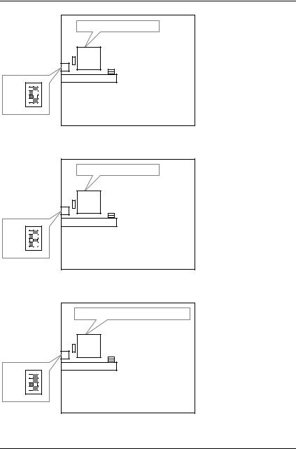
Table of Contents
Pentium 120 MHz
CPU
OFF ON
1
2
3
4
SW
5.Pentium 133 MHz
Pentium 133 MHz
CPU
OFF ON
1
2
3
4
SW
6.Pentium 150 MHz/P55C-150MHz
Pentium 150 MHz/P55C-150MHz |
CPU |
OFF ON
1
2
3
4
SW
7.Pentium 166 MHz/P55C-166MHz
7
GA-586HX
Pentium 166 MHz/P55C-166MHz |
CPU |
OFF ON
1
2
3
4
SW
8.Pentium 180 MHz
Pentium 180 MHz
CPU
OFF ON
1
2
3
4
SW
9.Pentium 200 MHz/P55C-200MHz
Pentium 200 MHz/P55C-200MHz |
CPU |
OFF ON
1
2
3
4
SW
10. P54CT-125 MHz
8
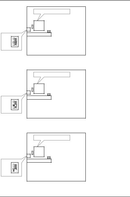
Table of Contents
P54CT-125 MHz
CPU
OFF ON
1
2
3
4
SW
11. P54CT-150 MHz
P54CT-150 MHz
CPU
OFF ON
1
2
3
4
SW
12. P54CT-166 MHz
P54CT-166 MHz
CPU
OFF ON
1
2
3
4
SW
9
GA-586HX
13. P54CTB-150 MHz
P54CTB-150 MHz
CPU
OFF ON
1
2
3
4
SW
14. P54CTB-166 MHz
P54CTB-166 MHz
CPU
OFF ON
1
2
3
4
SW
15. P54CTB-180 MHz
P54CTB-180 MHz
CPU
OFF ON
1
2
3
4
SW
10
Table of Contents
16. P54CTB-200 MHz
P54CTB-200 MHz
CPU
OFF ON
1
2
3
4
SW
17. AMDK575 MHz-P75
AMDK575 MHz-P75 |
CPU |
OFF ON
1
2
3
4
SW
18. AMDK590 MHz-P90
11
GA-586HX
AMDK5-90 MHz-P90 |
CPU |
OFF ON
1
2
3
4
SW
19. AMDK5-100 MHz-P100
AMDK5-100 MHz-P100 |
CPU |
OFF ON
1
2
3
4
SW
20. AMDK590 MHz-P120
AMDK5-90 MHz-P120 |
CPU |
OFF ON
1
2
3
4
SW
12
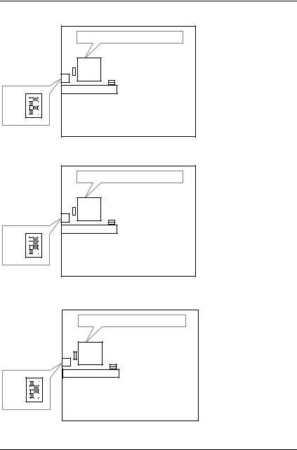
Table of Contents
21. AMDK5-100 MHz-P133
AMDK5-100 MHz-P133 |
CPU |
OFF ON
1
2
3
4
SW
22. AMDK5-P166
AMDK5-P166 |
CPU |
OFF ON
1
2
3
4
SW
23. AMDK5-P200
AMDK5-P200 |
CPU |
OFF ON
1
2
3
4
SW
13
GA-586HX
24. Cyrix 6x86-100 MHz-P120+
Cyrix6x86-100 MHz-P120+ |
CPU |
OFF ON
1
2
3
4
SW
25. Cyrix 6x86-110 MHz-P133+
Cyrix6x86-110 MHz-P133+ |
CPU |
OFF ON
1
2
3
4
SW
26. Cyrix 6x86-120 MHz-P150+
Cyrix6x86-120 MHz-P150+ |
CPU |
OFF ON
1
2
3
4
SW
14
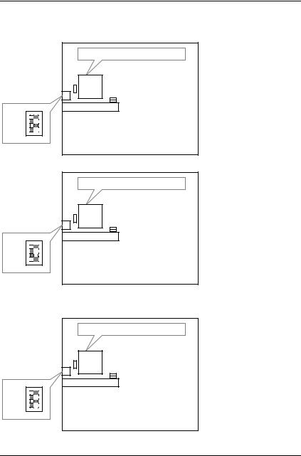
Table of Contents
27. Cyrix 6x86-133 MHz-P166+ |
|
||
|
Cyrix6x86-133 MHz-P166+ |
||
|
CPU |
|
|
OFF |
ON |
|
|
1 |
|
|
|
2 |
|
|
|
3 |
|
|
|
4 |
|
|
|
SW |
|
|
|
28. Cyrix 6x86L-P150+ |
2.8V |
|
|
|
Cyrix6x86L-P150+ |
2.8V |
|
|
CPU |
|
|
OFF |
ON |
|
|
1 |
|
|
|
2 |
|
|
|
3 |
|
|
|
4 |
|
|
|
SW |
|
|
|
29. Cyrix 6x86L-P166+ |
2.8V |
|
|
|
Cyrix6x86L-P166+ |
2.8V |
|
|
CPU |
|
|
OFF |
ON |
|
|
1 |
|
|
|
2 |
|
|
|
3 |
|
|
|
4 |
|
|
|
SW |
|
|
|
|
|
15 |
|

GA-586HX
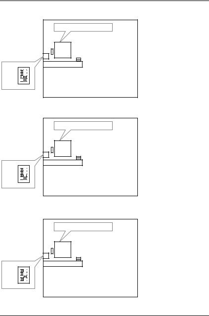
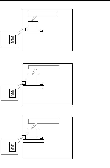
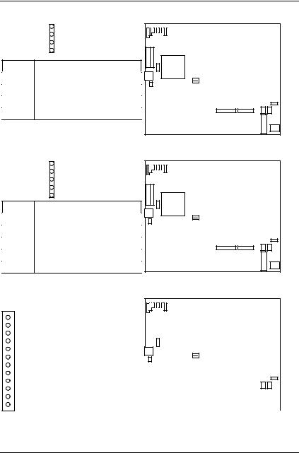
III. SRAM Install
16
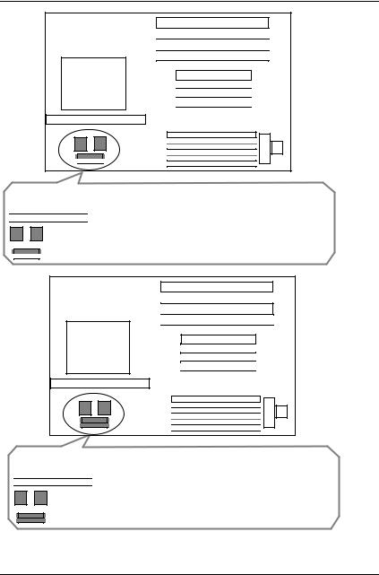
Table of Contents
CPU
Cache Size 256KB / Cacheable Memory Size 64 MB

 CN2: Cache Module
U7,U8 : SRAM Pipeline 256KB Onboard (32K*32) 2pcs.
* U5: Installed only (16K*8-15)
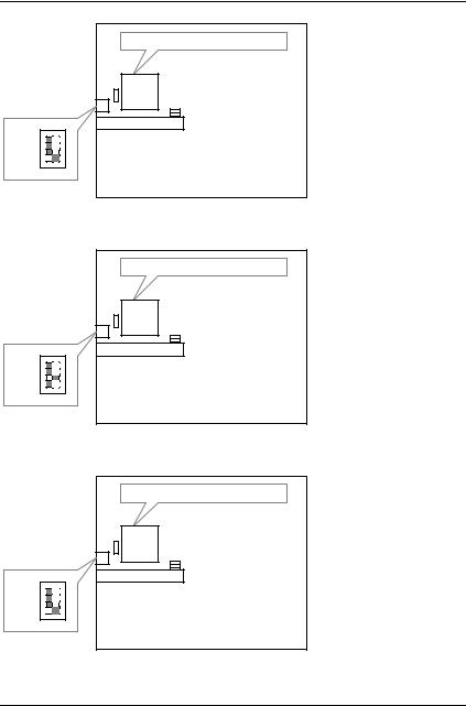
CPU
Cache Size 256KB / Cacheable Memory Size 512 MB

 CN2: Cache Module
U7,U8 : SRAM Pipeline 256KB Onboard (32K*32) 2pcs.
* U4, U5: Installed only (16K*8-15)
(U4 has to be installed only (16K*8-15))
17

GA-586HX
18
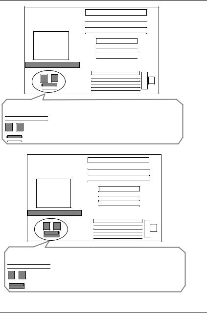
Table of Contents
CPU
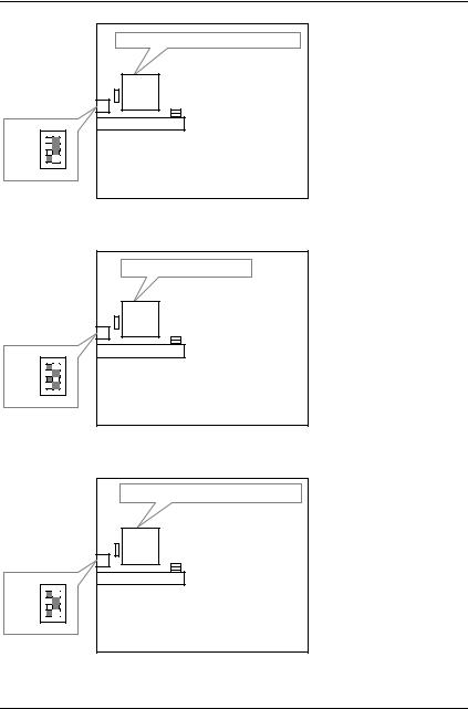
Cache Size 512KB / Cacheable Memory Size 64 MB

 CN2: Cache Module
U7,U8 : SRAM Pipeline 256KB Onboard (32K*32) 2pcs.
* U5: Installed only (16K*8-15)
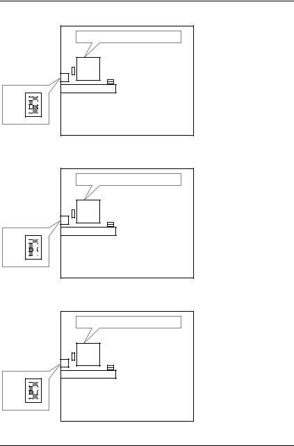
CPU
Cache Size 512KB / Cacheable Memory Size 512 MB

 CN2: Cache Module
U7,U8 : SRAM Pipeline 256KB Onboard (32K*32) 2pcs.
* U5: Installed only (16K*8-15)
(U4 has to be installed only (16K*8-15))
19
GA-586HX
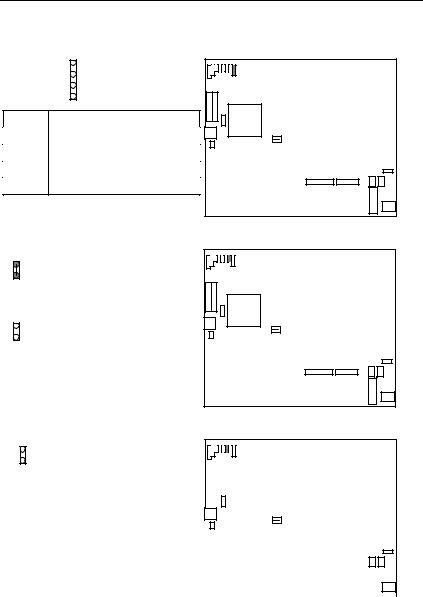
IV. Quick Installation Guide of Jumper setting:
HD: IDE Hard Disk Active LED |
|
|
|
1 |
1 |
Pin No. |
Function |
CPU |
1 |
LED anode (+) |
|
2 |
LED cathode (-) |
|
3 |
LED cathode (-) |
|
4 |
LED anode (+) |
|
GN: Green Function Switch |
|
|
Close: For system entering Green mode.
CPU
Open: Normal operation.
GD: Green Function LED
1
1
|
|
|
|
|
|
|
|
|
|
|
|
|
|
|
|
|
|
|
|
|
|
|
|
|
|
|
|
|
|
|
|
|
|
|
|
|
|
|
|
|
|
|
|
|
|
|
|
|
|
|
|
|
|
|
|
|
Pin No. |
Function |
|
|
|
|
|
|
|
CPU |
|
|
|
|
|
|
|
|
|
|
|
|
|
|
|
|
|
|
|
|
|
|
|
|
|
|
|
|
|
|
|
|
|
|
|
|
|
|
|
|
|
|
|||
|
1 |
LED anode (+) |
|
|
|
|
|
|
|
|
|
|
|
|
|
|
|
|
|
|
|
|
|
|
|
|
|
|
|
|
|
|
|
|
|
|
|
|
|
|
|
|
|
|
|
|
|
|
|
|
|
|
|
||
|
2 |
LED cathode (-) |
|
|
|
|
|
|
|
|
|
|
|
|
|
|
|
|
|
|
|
|
|
|
|
|
|
|
|
|
|
|
|
|
|
|
|
|
|
|
|
|
|
|
|
|
|
|
|
|
|
|
|
|
|
|
|
|
|
|
|
|
|
|
|
|
|
|
|
|
|
|
|
|
|
|
|
|
|
|
|
|
|
|
|
|
|
|
|
|
|
|
|
|
|
|
|
|
|
|
|
|
|
|
|
|
|
|
|
|
|
|
|
|
|
|
|
|
|
|
|
|
|
|
|
|
|
|
|
|
|
|
|
|
|
|
|
|
|
|
|
|
|
|
|
|
|
|
|
|
|
|
|
|
|
|
|
|
|
|
|
|
|
|
|
|
|
|
|
|
|
|
|
|
|
|
|
|
|
|
|
|
|
|
|
|
|
|
|
|
|
|
|
|
|
|
|
|
|
|
|
|
|
|
|
|
|
|
|
|
|
|
|
|
|
|
|
|
|
|
|
|
|
|
|
|
|
|
|
|
|
|
|
|
|
|
|
|
|
|
|
|
|
|
|
|
|
|
|
|
|
|
|
|
|
|
|
|
|
|
|
|
|
|
|
|
|
|
|
|
|
|
|
|
|
|
|
|
|
|
|
|
|
|
|
|
|
|
|
|
|
|
|
|
|
|
|
|
|
|
|
|
|
|
|
|
|
|
|
|
|
|
|
|
|
|
|
|
|
|
|
|
|
|
|
|
|
|
|
|
|
|
|
|
|
|
|
|
|
|
|
|
|
|
|
|
|
|
|
|
|
|
|
|
|
|
|
|
|
|
|
|
|
20
Table of Contents
RST: Reset Switch
Close: For hardware reset system.
CPU
Open: Normal operation.
TB: Turbo Switch
Close: For low speed (50MHz).
CPU
Open: For high speed (Normal).
* Don't switch TB function when system is live.
TD: Turbo LED Connector
1
Pin No. |
Function |
|
|
1 |
LED anode (+) |
|
|
2 |
LED cathode (-) |
|
|
1 |
CPU
21
GA-586HX |
|
|
SPK: Speaker Connector |
|
|
|
1 |
1 |
Pin No. |
Function |
CPU |
1 |
VCC |
|
2 |
NC |
|
3 |
NC |
|
4 |
Data |
|
PWR: Power LED and Key-Lock Connector |
||
|
1 |
1 |
Pin No. |
Function |
CPU |
|
||
1 |
LED anode (+). |
|
2 |
NC |
|
3 |
LED cathode (-). |
|
4 |
Key lock |
|
5 |
GND |
|
POWER: Power Connector
1
Pin No. |
Function |
|
|
|
|
|
|
|
|
|
|
|
|
|
|
|
|
|
|
|
|
1 |
Power Good signal. |
|
|
|
|
|
|
|
CPU |
|
|
|
|
|
|
|
|
|
|
|
|
|
|
|
|
|
|
|
|
|
|
|
|
|
|
|
|
|
|
|
|||
2,10,11,12 |
VCC (+5V) |
|
|
|
|
|
|
|
|
|
|
|
|
|
|
|
|
|
|
|
|
|
|
|
|
|
|
|
|
|
|
|
|
|
|
|
|
|
|
|
|
||
3 |
+12V |
|
|
|
|
|
|
|
|
|
|
|
|
|
|
|
|
|
|
|
|
|
|
|
|
|
|
|
|
|
|
|
|
|
|
|
|
|
|
|
|
|
|
4 |
-12V |
|
|
|
|
|
|
|
|
|
|
|
|
|
|
|
|
|
|
|
|
|
|
|
|
|
|
|
|
|
|
|
|
|
|
|
|
|
|
|
|
||
|
|
|
|
|
|
|
|
|
|
|
|
|
|
|
|
|
|
|
|
|
|
5,6,7,8 |
GND |
|
|
|
|
|
|
|
|
|
|
|
|
|
|
|
|
|
|
|
|
|
|
|
|
|
|
|
|
|
|
|
|
|
|
|
|
|
|
|
|
||
|
|
|
|
|
|
|
|
|
|
|
|
|
|
|
|
1 |
|
||||
|
|
|
|
|
|
|
|
|
|
||||||||||||
9 |
-5V |
|
|
|
|
|
|
|
|
|
|
|
|
|
|
|
|
|
|
|
|
|
|
|
|
|
|
|
|
|
|
|
|
|
|
|
|
|
|
|
|
||
|
|
|
|
|
|
|
|
|
|
|
|
|
|
|
|
|
|
|
|
|
|
|
|
|
|
|
|
|
|
|
|
|
|
|
|
|
|
|
|
|
|
|
|
22
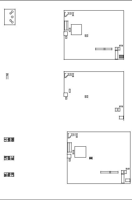
Table of Contents
J1: Keyboard Connector
1
2
3
4
5
Pin No. |
Function |
|
|
|
|
|
|
|
|
|
|
|
|
||
|
|
|
|
|
|
|
|
1 |
Key Clock. |
|
|
|
|
|
|
|
|
|
|
|
|
||
|
|
|
|
|
|
||
|
|
|
|
|
|
|
|
2 |
Key Data |
|
|
|
|
|
|
|
|
|
|
|
|
|
|
3 |
NC |
|
|
|
|
|
|
|
|
|
|
|
|
|
|
4 |
VCC (+5V) |
|
|
|
|
|
|
|
|
|
|
|
|
|
|
5 |
GND |
|
|
|
|
|
|
|
|
|
|
|
|
|
|
CPU
J9: CPU Cooling Fan Power Connector
1
|
|
|
|
|
|
|
|
|
|
|
|
|
|
|
|
|
|
|
|
|
|
|
|
|
|
|
|
|
|
|
|
|
|
|
|
|
|
|
|
|
|
|
|
|
|
|
|
|
|
|
|
Pin No. |
Function |
|
|
|
|
|
|
|
CPU |
|
|
|
|
|
|
|
|
|
|
|
|
|
|
|
|
|
|
|
|
|
|
|
|
|
|
|
|
|
|
|
|
|
|
|
|
|
|
|
|||
1 |
+12V |
|
|
|
|
|
|
|
|
|
|
|
|
|
|
|
|
|
|
|
|
|
|
|
|
|
|
|
|
|
|
|
|
|
|
|
|
|
|
|
|
|
|
|
|
|
|
|
|
||
2 |
GND |
|
|
|
1 |
|
|
|
|
|
|
|
|
|
|
|
|
|
|
|
|
|
|
|
|
|
|
|
|
|
|
|
|
|
|
|
|
|
|
|
|
|
|
|
|
|
|
|
|
||
|
|
|
|
|
|
|
|
|
|
|
|
|
|
|
|
|
|
|
|
|
|
|
|
|
|
|
|
|
|
|
|
|
|
|
|
|
|
|
|
|
|
|
|
|
|
|
|
|
|
|
|
|
|
|
|
|
|
|
|
|
|
|
|
|
|
|
|
|
|
|
|
|
|
|
|
|
|
|
|
|
|
|
|
|
|
|
|
|
|
|
|
|
|
|
|
|
|
|
|
|
|
|
|
|
|
|
|
|
|
|
|
|
|
|
|
|
|
|
|
|
|
|
|
|
|
|
|
|
|
|
|
|
|
|
|
|
|
|
|
|
|
|
|
|
|
|
|
|
|
|
|
|
|
|
|
|
|
|
|
|
|
|
|
|
|
|
|
|
|
|
|
|
|
|
|
|
|
|
|
|
|
|
|
|
|
|
|
|
|
|
|
|
|
|
|
|
|
|
|
|
|
|
|
|
|
|
|
|
|
|
|
|
|
|
|
|
|
|
|
|
|
|
|
|
|
|
|
|
|
|
|
|
|
|
|
|
|
|
|
|
|
|
|
|
|
|
|
|
|
|
|
|
|
|
|
|
|
|
|
|
|
|
|
|
|
|
|
|
|
|
|
|
|
|
|
|
|
|
|
|
|
|
|
|
|
JP1,2: System Speed Selection (For Motherboard with JP1, JP2)
JP2 |
1 |
: For 50 MHz system speed |
|
|
|
||
JP1 |
1 |
|
|
JP2 |
1 |
CPU |
|
: For 60 MHz system speed |
|||
|
|
||
JP1 |
1 |
|
|
JP2 |
1 |
: For 66 MHz system speed |
|
|
|
||
JP1 |
1 |
|
1
1
23

GA-586HX
JP3: CPU INT./EXT. FREQ. (For Motherboard with JP3)
1 |
1 |
|
x 1.5 |
1 |
1 |
|
x 2.5 |
x 2
1
CPU
x 3
CN3,4,J2,3,4,5,6: I/O Ports Connector
1
1
RED LINE
CPU
CN3: For Primary IDE port
1
1
RED LINE
CPU
CN4: For Secondary IDE port
24
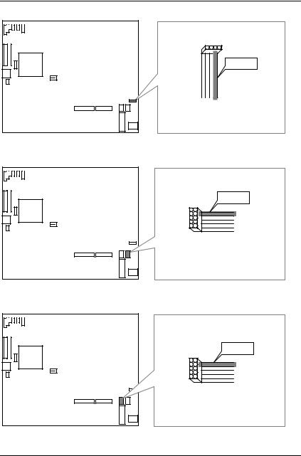
Table of Contents
|
1 |
CPU |
RED LINE |
1
J2: For PS/2 Mouse port
RED LINE
1
CPU
1
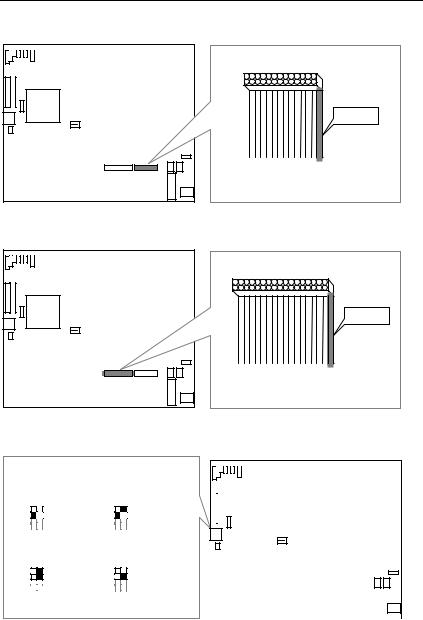
J3: For COM A
RED LINE
1
CPU
1
J4: For COM B
25
GA-586HX
1
CPU
RED LINE
1
J5: For LPT port
1
CPU |
RED LINE |
1
J6: For Floppy port
SW1, SW2: For CPU INT./EXT. FREQ.
|
|
|
|
|
|
|
|
|
|
|
|
|
|
1 |
|
|
|
|
|
|
|
|
|
|
|
|
|
|
|
|
|
OFF |
|
|
|
|
ON |
OFF |
|
|
|
|
|
|
ON |
|
|
|
|
|
|
|
|
|
|
|
|
|
|
|
|
|
|
SW1 |
|
|
|
|
|
SW1 |
|
|
|
|
|
|
|
|
|
|
|
|
|
|
|
|
|
|
|
|
|
|
|
|
|
SW2 |
|
|
|
|
x 1.5 |
SW2 |
|
|
|
|
|
|
x 2 |
|
|
|
CPU |
|
|
|
|
|
|
|
|
|
|
|
|
|
|
|
|
|
|
|
|
|
|
|
|
|
|
|
|
|
|
|
|
|
|
|
|||||||||||
|
|
|
|
|
|
|
|
|
|
|
|
|
|
|
|
|
|
|
|
|
|
|
|
|
|
|
|
|
|||
|
|
|
|
|
|
|
|
|
|
|
|
|
|
|
|
|
|
|
|
|
|
|
|
|
|
|
|
|
|||
|
|
|
|
|
|
|
|
|
|
|
|
|
|
|
|
|
|
|
|
|
|
|
|
|
|
|
|
|
|
|
|
|
|
|
|
|
|
|
|
|
|
|
|
|
|
|
|
|
|
|
|
|
|
|
|
|
|
|
|
|
|
|
|
|
|
|
|
|
|
|
|
|
|
|
|
|
|
|
|
|
|
|
|
|
|
|
|
|
|
|
|
|
|
|
|
OFF |
|
|
|
|
ON |
OFF |
|
ON |
|
|
|
|
|
|
|
|
|
|
|
|
|
|
|
|
|
|
|||||
SW1 |
|
|
|
|
|
SW1 |
|
|
|
|
|
|
|
|
|
|
|
|
|
|
|
|
|
|
|
|
|||||
|
|
|
|
|
|
|
|
|
|
|
|
|
|
|
|
|
|
|
|
|
|
|
|
|
|
|
|||||
|
|
|
|
|
|
|
|
|
|
|
|
|
|
|
|
|
|
|
|
||||||||||||
SW2 |
|
|
|
|
x 2.5 |
SW2 |
|
x 3 |
|
|
|
|
|
|
|
|
|
|
|
|
|
|
|
|
|
|
|||||
|
|
|
|
|
|
|
|
|
|
|
|
|
|
|
|
|
|
||||||||||||||
|
|
|
|
|
|
|
|
|
|
|
|
|
|
|
|
|
|
||||||||||||||
|
|
|
|
|
|
|
|
|
|
|
|
|
|
|
|
|
|
|
|
|
|
|
|
|
|
|
|
|
|
||
|
|
|
|
|
|
|
|
|
|
|
|
|
|
|
|
|
|
|
|
|
|
|
|
|
|
|
|
|
|
|
|
|
|
|
|
|
|
|
|
|
|
|
|
|
|
|
|
|
|
|
|
|
|
|
|
|
|
|
|
|
|
|
|
|
|
|
|
|
|
|
|
|
|
|
|
|
|
|
|
|
|
|
|
|
|
|
|
|
|
|
|
|
|
|
|
|
|
|
|
|
|
|
|
|
|
|
|
|
|
|
|
|
|
|
|
|
|
|
|
|
|
|
|
|
|
|
|
|
|
|
|
|
|
|
|
|
|
|
|
|
|
|
|
|
|
|
|
|
|
|
|
|
|
|
|
|
|
|
|
|
|
|
|
|
|
|
|
|
|
|
|
|
|
|
|
|
|
|
|
|
|
|
|
|
|
|
|
|
|
|
|
|
|
|
|
|
|
|
|
|
|
|
|
|
|
|
|
|
|
|
|
|
|
|
|
|
|
|
|
|
|
|
|
26
Table of Contents
SW3, SW4: For System Speed |
|
|
|
|
|
|
|
|
|
|
|
|
|
|
|
|
|||||
|
|
|
|
|
|
|
|
|
|
|
|
|
|
|
|
||||||
|
|
|
|
|
|
|
|
|
|
|
|
|
|
|
|
|
|
|
|
|
|
OFF |
|
|
|
|
ON |
1 |
|
|
|
|
|
|
|
|
|
|
|
|
|
|
|
SW3 |
|
|
|
|
50 MHz |
|
|
|
|
|
|
|
|
|
|
|
|
|
|
|
|
|
|
|
|
|
|
|
|
|
|
|
|
|
|
|
|
|
|
|
|
||
|
|
|
|
|
|
|
|
|
|
|
|
|
|
|
|
|
|
|
|
||
SW4 |
|
|
|
|
|
|
|
|
|
CPU |
|
|
|
|
|
|
|
|
|
|
|
|
|
|
|
|
|
|
|
|
|
|
|
|
|
|
|
|
|
|
|
||
|
|
|
|
|
|
|
|
|
|
|
|
|
|
|
|
|
|
|
|
||
OFF |
|
ON |
|
|
|
|
|
|
|
|
|
|
|
|
|
|
|
|
|||
SW3 |
|
|
|
|
60 MHz |
|
|
|
|
|
|
|
|
|
|
|
|
|
|
|
|
|
|
|
|
|
|
|
|
|
|
|
|
|
|
|
|
|
|
|
|
||
|
|
|
|
|
|
|
|
|
|
|
|
|
|
|
|
|
|
|
|
||
SW4 |
|
|
|
|
|
|
|
|
|
|
|
|
|
|
|
|
|
|
|||
OFF |
|
|
|
|
ON |
|
|
|
|
|
|
|
|
|
|
|
|
|
|
|
|
|
|
|
|
|
|
|
|
|
|
|
|
|
|
|
|
|
|||||
SW3 |
|
|
|
|
66 MHz |
|
|
|
|
|
|
|
|
|
|
|
|
|
|
|
|
|
|
|
|
|
|
|
|
|
|
|
|
|
|
|
|
|
|
|
|
||
|
|
|
|
|
|
|
|
|
|
|
|
|
|
|
|
|
|
|
|
||
SW4 |
|
|
|
|
|
|
|
|
|
|
|
|
|
|
|
|
|
|
|||
|
|
|
|
|
|
|
|
|
|
|
|
|
|
|
|
|
|
|
|
|
|
|
|
|
|
|
|
|
|
|
|
|
|
|
|
|
|
|
|
|
|
|
|
|
|
|
|
|
|
|
|
|
|
|
|
|
|
|
|
|
|
|
|
|
|
V.Top Performance Test Setting:
Note:Users have to modify the value for each item in chipset features as follow: Note:60ns EDO-60ns DRAM is necessary for top performance setting.
Chipset features setup
ROM PCI / ISA BIOS
CHIPSET FEATURES SETUP
AWARD SOFTWARE, INC.
Auto Configuration |
: Disabled |
Memory Parity/ECC Check |
|
|
: Disabled |
||||
|
|
Single Bit Error Report |
|
|
: Enabled |
||||
DRAM RAS# Precharge Time |
: 3 |
L2 Cache Cacheable size |
|
|
: 64 MB |
||||
DRAM R/W Leadoff Timing |
: 6/5 |
Chipset NA # Asserted |
|
|
: Enabled |
||||
Fast RAS# To CAS# Delay |
: 2 |
Pipeline Cache Timing |
|
|
: Fastest |
||||
DRAM Read Burst (EDO/FPM) |
: x222/x333 |
Passive Release |
|
|
|
|
|
: Enabled |
|
DRAM Write Burst Timing |
: x222 |
Delayed Transaction |
|
|
: Disabled |
||||
Turbo Read Leadoff |
: Disabled |
|
|
|
|
|
|
|
|
DRAM Speculative Leadoff |
: Enabled |
|
|
|
|
|
|
|
|
Turn-Around Insertion |
: Disabled |
|
|
|
|
|
|
|
|
ISA Clock |
: PCI CLK/4 |
|
|
|
|
|
|
|
|
System BIOS Cacheable |
: Enabled |
|
|
|
|
|
|
|
|
Video BIOS Cacheable |
: Enabled |
|
|
|
|
|
|
|
|
|
|
|
|
|
|
|
|
||
8 Bit I/O Recovery Time |
: 1 |
ESC : Quit |
|
|
|
|
|
: Select Item |
|
|
|
|
|
||||||
16 Bit I/O Recovery Time |
: 1 |
F1 |
: Help |
PU/PD/+/- |
|
: Modify |
|||
Memory Hole At 15M-16M |
: Disabled |
F5 |
: Old Values |
(Shift)F2 |
|
: Color |
|||
Peer Concurrency |
: Enabled |
F6 |
: Load BIOS Defaults |
|
|
|
|||
DRAM ECC/PARITY Select |
: Parity |
F7 |
: Load Setup Defaults |
|
|
|
|||
|
|
|
|
|
|
|
|
|
|
27

GA-586HX
The author assumes no responsibility for any errors or omissions which may appear in this document nor does it make a commitment to update the information contained herein.
IBM PC/AT, PC/XT are trademarks of International Business Machine Corporation.
PENTIUM is a trademark of Intel Corporation. AWARD is a trademark of Award Software, Inc.
MS-DOS WINDOWS NT are registered trademarks of Microsoft Corporation. UNIX is a trademark of Bell Laboratories.
OCTOBER 22, 1996 Taipei, Taiwan
28
 Loading...