


SR100
SR100 - (AS05190)
Centralina di controllo
ISTRUZIONI PER L’INSTALLAZIONE
Control unit
INSTRUCTIONS FOR INSTALLATIONS
I UK F E
D P NL GR
I
Grazie per avere scelto GIBIDI.
LEGGERE ATTENTAMENTE QUESTO MANUALE PRIMA DI PROCEDERE ALL’INSTALLAZIONE.
AVVERTENZE: Questo prodotto è stato collaudato in GI.BI.DI. verificando la perfetta corrispondenza delle caratteristiche alle direttive vigenti.
GI.BI.DI. S.r.l. si riserva la facoltà di modificare i dati tecnici senza avviso, in funzione dell’evoluzione del prodotto.
SMALTIMENTO: GI.BI.DI. consiglia di riciclare i componenti in plastica e di smaltire in appositi centri abilitati i componenti elettronici evitando
di contaminare l'ambiente con sostanze inquinanti.
UK
Thank you for choosing GI.BI.DI.
PLEASE READ CAREFULLY THIS MANUAL BEFORE PROCEEDING WITH THE INSTALLATION.
WARNINGS: This product has been tested in GI.BI.DI. verifying the perfect correspondence of the characteristics to the current directive.
GI.BI.DI. S.r.l. reserves the right to modify the technical data without prior notice depending on the product development.
DISPOSAL: GI.BI.DI. advises recycling the plastic components and to dispose of them at special authorised centres for electronic
components thus protecting the environment from polluting substances.
F
Merci d’avoir choisi GI.BI.DI.
NOUS VOUS PRIONS DE BIEN VOULOIR LIRE ATTENTIVEMENT CE MANUEL AVANT DE PROCÉDER À L’INSTALLATION.
AVERTISSEMENT: Ce produit a été testé chez GI.BI.DI. afin de contrôler la correspondance parfaite des caractéristiques avec les règles en vigueur.
GI.BI.DI. S.r.l. se réserve la faculté de modifier les données techniques sans aucun préavis suivant l’évolution de ses produits.
ELIMINATION : GI.BI.DI. conseille de recycler les composants en plastique et de remettre les composants électroniques à des centres
spécialisés pour éviter de polluer l'environnement avec des substances polluantes.
E
Gracias por haber elegido GI.BI.DI.
POR FAVOR LEER CON ATENCIÓN ESTE MANUAL ANTES DE PROCEDER CON LA INSTALACIÓN.
ADVERTENCIAS: Este producto ha sido ensayado en GI.BI.DI. averiguando la perfecta correspondencia de las características a las normas vigentes.
La empresa GI.BI.DI. S.r.l. se reserva el derecho de modificar los datos técnicos sin previo aviso, en función de la evolución del producto.
ELIMINACION: GI.BI.DI. aconseja reciclar los componentes de plástico y llevar los componentes electrónicos a los centros de recogida
correspondientes evitando de esta manera la contaminación ambiental con sustancias perjudiciales.
D
Vielen Dank, dass Sie sich für GI.BI.DI. entschieden haben.
BITTE LESEN SIE VORSICHTIG DIESEN MANUAL BEVOR MIT DER ANGLAGE VORZUGEHEN.
WARNUNGEN: Dieses Produkt wurde in GI.BI.DI. geprüft um die perfekte Entsprechung der merkmäle an die geltende vorschriften zu prüfen.
GI.BI.DI. S.r.l. behält sich das recht vor, die technischen daten der produktentwicklung entsprechend ohne voranzeige abzuändern.
ENTSORGUNG: GI.BI.DI. empfiehlt, Kunststoffkomponenten dem Recycling zuzuführen und elektronische Komponenten in behördlich
genehmigten Zentren zu entsorgen, um die Verschmutzung der Umwelt durch Schadstoffe zu verhindern.
SR100
P
Obrigado por ter escolhido a GI.BI.DI.
LER COM ATENÇÃO ESTE MANUAL ANTES DE PROCEDER COM A INSTALAÇÃO.
ADVERTÊNCIA: Este produto foi testado em GI.BI.DI. verificando a correspondência perfeita das características ao normas vigentes.
A GI.BI.DI. S.r.l. reserva-se o direito de modificar os dados técnicos sem pré-aviso em função de evolução do produto.
ELIMINAÇÃO: GI.BI.DI. Aconselha a reciclar as componentes em plástico e a eliminar as componentes electrónicas em centros habilitados
evitando desta forma poluir o ambiente com substâncias poluentes.
NL
Dank u voor uw keuze van GI.BI.DI.
LEES DEZE GEBRUIKSAANWIJZING ZEER AANDACHTIG ALVORENS DE INSTALLATIE AAN TE VATTEN.
WAARSCHUWINGEN: Dit product werd gekeurd in Gi.Bi.Di. Er werd nauwlettend gecontroleerd of de kenmerken van het product perfect overeenkomen met de
geldige richtlijnen.
GI.BI.DI. S.r.l. behoudt zich het recht voor de technische gegevens te wijzigen zonder waarschuwing vooraf, als dat nodig is voor de evolutie van het product.
VERWERKING: GI.BI.DI. adviseert om de kunststof componenten te recycleren en de elektronische componenten af te voeren naar erkende
inzamelpunten, om te voorkomen dat het milieu verontreinigd wordt door vervuilende stoffen.
GR
Ευχαριστούμε που επιλέξατε τα προιόντα GI.BI.DI.
ΠΑΡΑΚΑΛΟΥΜΕ ΝΑ ΔΙΑΒΑΣΤΕ ΠΡΟΣΕΚΤΙΚΑ ΑΥΤΕΣ ΤΙΣ ΟΔΗΓΙΕΣ ΠΡΙΝ ΤΗΝ ΕΓΚΑΤΑΣΤΑΣΗ.
ΣΗΜΕΙΩΣΗ: Η εταιρία GI.BI.DI. έχει ελέγξει αυτό το προιόν όσον αφορά την τέλεια προσαρμογή των χαρακτηριστικών του στην ισχύουσα νομοθεσία.
Η εταιρία GI.BI.DI. S.r.l. διατηρεί το δικαίωμα αλλαγών των τεχνικών προδιαγραφών χωρίς προϋγούμενη ειδοποίηση και ανάλογα με την ανάπτυξη των
προϊόντων της.
ΔΙΑΘΕΣΗ: Η GI.BI.DI. σας συμβουλεύει να ανακυκλώσετε τα πλαστικά εξαρτήματα και να διαθέσετε τα ηλεκτρονικά εξαρτήματα μετά την
απαξίωση τους, σε εξειδικεύμενα κέντρα που υπάρχουν για τον σκοπό αυτό,συμβάλοντας έτσι στην προστασία του περιβάλλοντος απο τις
παρενέργειες της μόλυνσης.
SR100
91
027G1
F1
DL5
T1
DL4
DIP1
RL1 RL2
DIP2
F2
START
DL8
DL1
DL2
DL3
J3
LEARN
SW12
SW11
A C B
A C B
DL6
RX
M1 M2 M3 M4
1 2 3
PHASE
NEUTRAL
230 Vac
230 Vac
4
EARTH
5 6 7 8
EARTH
LAMP
230Vac 40W MAX
9
101112 13 14 15
LAMP
MOTOR
MOTOR
OPEN
COM
M
+24Vdc
MOTOR
CLOSE
COM
G_OP
16
17 18
ANT
PHOTO
G_CL
START
SAF
GND
92
SR100
9
UK
Control unit
Type
Power supply
N° motors
Motor power supply
Flashing light
Accessories power supply
Functioning time
Pause time
Radio receiver
Operating temperature
Electronic control unit for the automation
SR100 / AS05190
of a shutter motor
230Vac monophase 50/60 Hz
230Vac 25W max
24Vdc 1,2W max
433,92 Mhz on board
TECHNICAL SPECIFICATIONS / FUNCTIONS
• Red warning led of n.c. contacts (photo).
• Green warning leds of n.o. contacts (start, general_open, general_close).
• Green warning leds of phases during time learning procedure.
• Yellow warning led for emergences
• Red warning led of radio codes learning
• Key LEARN to memorize radio codes
• Key START on board.
• Possibility of using the SAF input as limit switch.
• Time self- learning.
INSTALLATION WARNINGS
1
230 Vac
125 s max
125 s max
-20°C +60°C
• Before proceeding with the installation, fit a magnetothermal or differential switch with a maximum capacity of
10A upstream of the system. The switch must guarantee omnipolar separation of the contacts, with an opening
distance of at least 3 mm.
• To prevent possible interference, differentiate and always keep the power cables (minimum cross-section
1,5mm²) separate from the signal cables (minimum cross-section 0,5mm²).
• Make the connections referring to the following tables and to the attached screen-print. Be extremely careful to
connect in series all the devices that must be connected to the same N.C. (normally closed) input, and in
parallel all the devices that share the same N.O. (normally open) input. Incorrect installation or improper use of
the product may compromise system safety.
• Keep all the materials contained in the packaging away from children, since they pose a potential risk.
• The manufacturer declines all responsibility for improper functioning of the automated device if the original
components and accessories suitable for the specific automation are not used.
• At the end of the installation, always check carefully the proper functioning of the system and the devices used.
• This instruction manual addresses people qualified for the installation of “live equipment”. Therefore, good
technical knowledge and professional practice in compliance with the regulations in force are required.
• Maintenance must be carried out by qualified personnel.
• Before carrying out any cleaning or maintenance operation, disconnect the control unit from the mains.
• This control unit may only be used for the purpose for which it was designed.
• Use of the product for purposes different from the intended use has not been tested by the manufacturer,
therefore any work is carried out on full responsibility of the installer.

10
UK
• Mark the automated gate with visible warning plates.
• Warn the user that children and animals may not play or stand around near the gate.
• Appropriately protect the dangerous points (for example, use a sensitive frame).
WARNINGS FOR THE USER
In the event of an operating fault or failure, cut the power upstream of the control unit and call Technical Service.
Periodically check functioning of the safety devices. Any repairs must be carried out by specialised personnel using
original and certified materials.
The product is not to be used by children or people with reduced physical, sensory or mental capabilities, or lack of
experience and knowledge, unless they have been given supervision or instruction. Do not intervene on the board for
regulations and/or maintenance.
WARNING: IMPORTANT SAFETY INSTRUCTIONS
For people's safety, it is important to follow these instructions.
Please keep this manual.
SR100
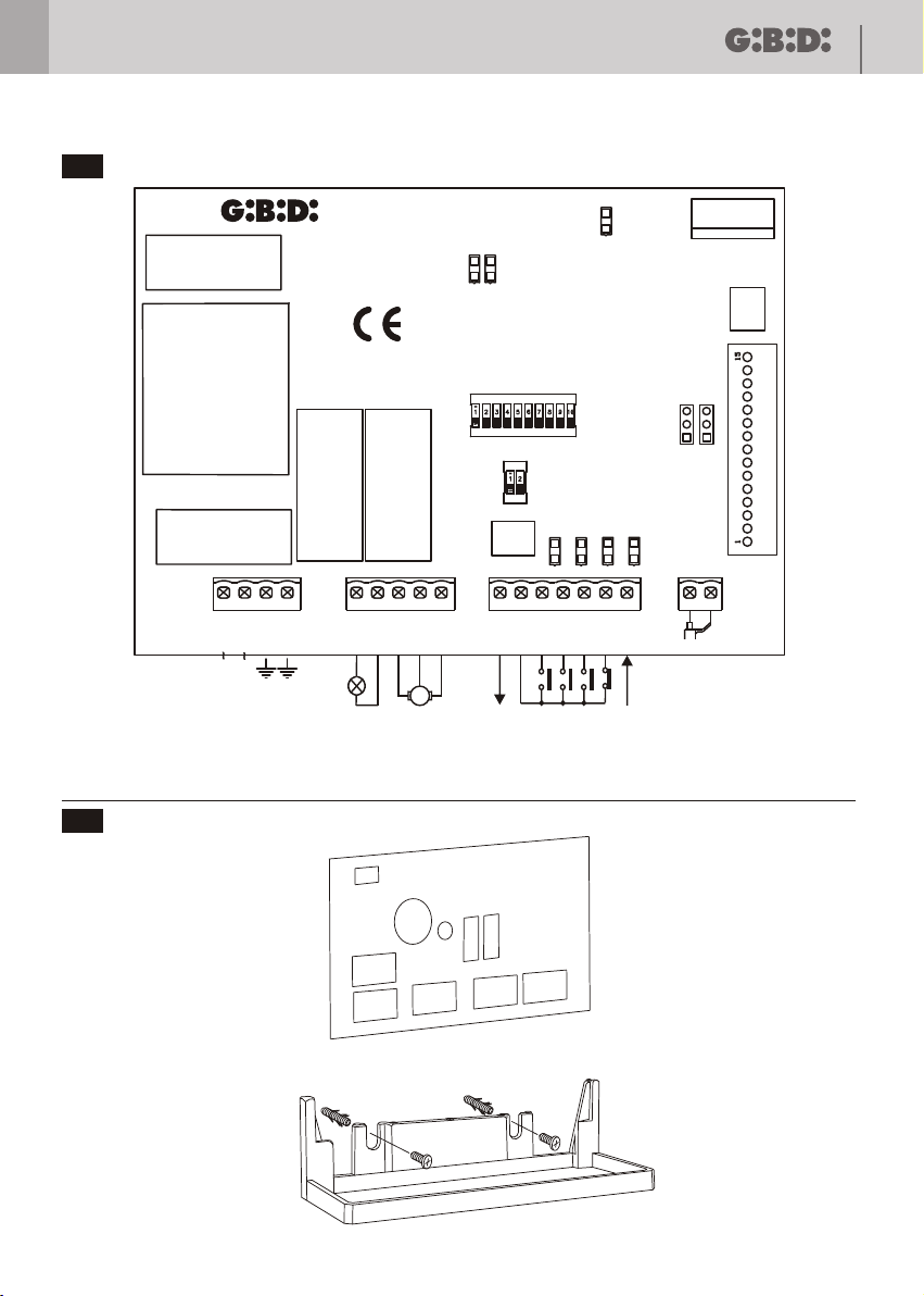
ELECTRICAL CONNECTIONS: TERMINALBOARDS
TerminalM1Position
1
2
3
4
5
M2
M3
M4
J3
6
7
8
9
10
11
12
13
14
15
16
17
18
Connector for connexion to the programmer PRG_01
Signal
N
L
EARTH
EARTH
LAMP
LAMP
OPEN
COM
CLOSE
24VDC
GND
G_OP
G_CL
START
PHOTO
SAF
+ ANT
- ANT
Description
Neutral power supply 230 Vac
Power supply phase 230 Vac
Ground connection
Ground connection
Flashing light output 230Vac 25W
Flashing light output 230Vac 25W
Motor connection (opening)
Common motor
Motor connection (closing)
External accessories 24 Vdc power supply
External accessories power supply. Common Inputs – Outputs
Input GENERAL OPEN (N.O.)
Input GENERAL_CLOSE (N.O.)
Input START (N.O.)
Input PHOTOCELL (N.C.). Active only during closing.
Input SAFETY DEVICES. See DIP 9-10
Input ANTENNA SIGNAL
Input ANTENNA BRAID
Fixed output to be used for
flashing light with flashing circuit
SR100
PROTECTION FUSES
11
UK
Position
F1
F2
Value
500 mA
5 A
Type
RAPIDO
RAPIDO
Description
Accessories power supply input protection
Board protection on 230 Vac power supply input
FUNCTIONS PROGRAMMING ( DIP SWITCH DIP1)
The settings are memorized during the pause phase (door closed).
DIP
DIP 1
DIP 2
DIP 3
DIP 2
DIP 3
DIP 2
DIP 3
DIP 2
DIP 3
Status
ON
OFF
OFF
OFF
ON
OFF
OFF
ON
ON
ON
Function Description
TIME
LEARNING
STEP – STEP
STOP STOP
STEP - STEP
CONDOMINIUM
NOT ENABLED
Enables the time learning procedure
Normal functioning
I Start pulse: OPENS
II Start pulse: STOPS (it will not close automatically)
III Start pulse: CLOSES
IV Start pulse: STOPS
I Start pulse: OPENS
II Start pulse: CLOSES
III Start pulse: OPENS
During opening, it does not receive other START commands after the first one, in
pause other START commands reload the pause time.
I Start pulse: OPENS
Next Start pulses: uninfluential
Pause from FCA or end of opening time
Start pulse during pause: reloads pause time (if automatic closing is enabled)
or CLOSES (if automatic closing is disabled)
Start pulse during closing: OPENS
DIP 4
DIP 5
DIP 8
DIP 5
DIP 8
DIP 5
DIP 8
ON
OFF
OFF
ININFL.
ON
OFF
ON
ON
EXTERNAL
COMMANDS
MANAGEMENT
RADIO INPUT
MANAGEMENT
The keys GENERAL_OPEN and GENERAL_CLOSE work with DEAD MAN logic.
Keeping the key pressed, the motion stops for one second and then the manoeuvre
starts.
The key GENERAL_OPEN manages only opening. Keeping the key pressed, the
motion stops for one second and then the manoeuvre starts.
The key GENERAL_CLOSE manages only the closing. Keeping the key pressed, the
motion stops for one second, then the manoeuvre starts.
Channel 1 transmitter: opens
Channel 3 transmitter: closes
Channel 2 and 4 transmitter: stops the motion
The control unit recognizes only one radio input set with the DIP 6 and 7
The control unit recognizes only one radio input set with the DIP 6 and 7 but:
the continuous pressure for 3 s on the channel 1 of the transmitter manages the
opening of ALL the control units on which the transmitter is memorized;
the continuous pressure for 3 s on the channel 3 of the transmitter manages the
closing of ALL the control units on which the transmitter is memorized.

12
UK
DIP
DIP 6
DIP 7
DIP 6
DIP 7
DIP 6
DIP 7
DIP 6
DIP 7
DIP 9
DIP 10
DIP 9
DIP 10
DIP 9
DIP 10
DIP 9
DIP 10
Status
OFF
OFF
OFF
ON
ON
OFF
ON
ON
OFF
OFF
OFF
ON
ON
OFF
ON
ON
Function
RADIO CHANNELS
SETTING
SAFETY INPUT
MANAGEMENT
SR100
Description
Channel 1 of the transmitter works as START.
Channel 2 of the transmitter works as START.
Channel 3 of the transmitter works as START.
Channel 4 of the transmitter works as START.
It sets the SAF input as STOP with contact NC.
In case of intervention:
door closed: the control unit does not open;
in opening: it stops the motion and the next START will cause the closing;
in pause: it does not allow closing and the next start will cause the closing;
in closing: it stops the motion and the next start will cause the opening.
It sets the SAF input as STOP with contact NO.
In case of intervention:
Doro closed: the control unit does not open;
in opening: it stops the motion and the next start will cause the closing;
in pause: it does not allow closing and the next start will cause closing;
in closing: it stops the motion and the next start will cause the opening.
Please make sure that the dip STOP NC is on OFF.
It sets the SAF input as 8K2 EDGE WITHOUT LIMIT SWITCHES.
In case of intervention:
door closed: the control unit does not open;
in opening: stop and motion inversion for 2 s. at next start pulse the motion starts in
the obstacle-freeing direction;
in pause: it does not allow closing and the next start will cause closing;
in closing: stop and motion inversion for 2 s. At next start pulse the motion restarts
in the obstacle-freeing direction.
It sets the SAF input as 8K2 EDGE WITH LIMIT SWITCHES.
The functioning is the same as the previous point, but with possibility of reading the
limit switches switch
The enabling of this switch before the edge activation is recognized as limit switch.
In this case, the control unit is not blocked because of the edge intervention.
It is necessary that the switch connects in parallel to the 8K2 internal resistor of the
edge another one having the same value. (3)
DEFAULT SETTINGS
DIP 1 ÷ 10 all OFF
93
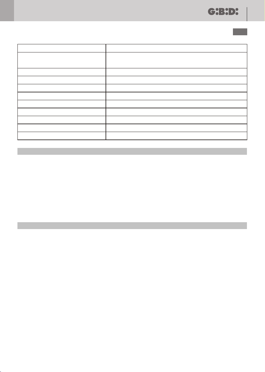
SENSITIVE EDGE
8K2
EDGE INTERNAL RESISTANCE
If the 8K2 external resistor is always in parallel to the edge, the intervention of the same edge is recognized as limit
switch.
CONNECTION TO THE
SR100 CONTROL UNIT
ADDITIONAL 8K2 RESISTANCE
LIMIT SWITCH ASEMBLED
NEAR THE CLOSING

SR100
FUNCTIONS SETTING ( DIP SWITCH DIP2)
Settings are memorized when the door is closed.
13
UK
DIP
DIP1
DIP 2
Status
ON
OFF
ON
OFF
Function
PHOTOCELL
STOP NC
DEFAULT SETTINGS
DIP1
DIP2ONON
SIGNALLING LEDS
Led
DL1
DL2
DL3
DL4
DL5
DL6
DL7
Colour
Green
Green
Green
Green
Yellow
Red
Red
Signal
GENERAL OPEN
GENERAL CLOSE
START
MEMO
SAFETY
PHOTOCELL
RADIO
ON BOARD RADIO MANAGEMENT
SPECIFICATIONS
Radio receiver 433,92 MHz
Memorizable codes max 200
Description
Disables PHOTO input
PHOTO input enabled
Disables SAF input set as STOP with NC contact
Enables SAF input set as STOP with NC contact.
Enables 8K2 edge reading
Description
It switches on when the contact is closed
It switches on when the contact is closed
It switches on when the contact is closed
See “Times learning procedure”
The led switches on with the SAF input enabled. It remains on for 2 s, then it
switches off and, after a few seconds, on again.
It switches off when the photocell contact opens
See “On board radio management”
CODES LEARNING
Press the LEARN key, the DL8 led switches on (it remains on for 6 s, then it switches off).
Press the key selected with the dip n° 6 – 7 of the transmitter that has to be set, and the receiver gives a start
command to the control unit. Without pressing again the LEARN key, it is possible to memorize other transmitters of
the same kind one after the other until the DL8 led remains on. After the learning of the last transmitter, wait until the
led switches off (about 6 s) to indicate that the system has left the learning procedure and is now ready for the
standard work.
Without pressing the LEARN key, it is possible to memorize the transmitters just by pressing simultaneously the keys
1 and 2 of a transmitter already memorized on the control unit for about 6 s. In this way, the transmitter enters the code
learning mode; it is now necessary only to press any of the keys of the new transmitter that has to be memorized.
MEMORY DELETION
In case of mistake, or when the complete deletion of all codes is necessary, press the LEARN key (the red led
switches on) and keep it pressed until the led switches off.

14
UK
CONFIGURATION JUMPER
SW11
Configuration
OPEN
C - B
A - C
Configuration
OPEN
A - C
TIMES LEARNING PROCEDURE
1. When the door is closet, place the DIP n°1 (DIP SWITCH DIP1) on ON. The green led DL4 flashes fast.
In this phase, if the DIP n°1 is put on OFF you leave the procedure, the memorized data remain stored and the
next START command will cause the opening.
2. START → The motor moves in opening. The green led DL4 keeps on flashing fast. The DIP n° 1 becomes
3. START → The motor stops in opening and the green led DL4 switches on fixed. The control unit waits for
If in this phase the DIP n°1 is put on OFF, you leave the procedure, only saving the work time and disabling the
automatic closing. The green led DL4 switches off and the next START command will cause the closing.
4. START → The pause time counting starts. The green led DL4 flashes slowly.
In this phase, if the DIP n°1 is put on OFF, you leave the procedure, only saving the work time and disabling the
automatic closing. The green led DL4 switches off and the next START command will cause the closing.
5. START → It ends the pause time counting, the work time and the pause time are memorized. The green
led DL4 remains on fixed.
6. To leave the times learning procedure, put the DIP n° 1 on OFF and the next START command or
GENERAL_CLOSE will cause the closing.
To modify the memorized times, it is necessary to repeat the above procedure.
Functioning
HCS ROLLING
DIP SWITCH
Functioning
NORMAL
uninfluential.
commands.
mode
HCS FIX
mode
AUA
Description
Standard rolling code functioning with variable code
Rolling code functioning with fixed code manageable with PRG_01 Consolle
Fixed code functioning with dip switch
SW12
Description
Standard functioning
A transmitter set by means of the PRG_01 programmer as another one is
automatically memorized in the event of continuous transmission for 5 s (HCS
ROLLING)
SR100
WARNING
During the times learning phase, the PHOTO, SAF, GENERAL_OPEN, GENERAL_CLOSE are disabled.
If the radio command is used as START, pay attention to the correct configuration of the dip n. 5 – 6 – 7 – 8.
DEFAULT VALUES
Work time: 30 s
Automatic closing disabled.

SR100
CE Declaration of conformity
The manufacturer:
GI.BI.DI. S.r.l.
Via Abetone Brennero, 177/B,
46025 Poggio Rusco (MN) ITALY
Declares that the products:
ELECTRONIC CONTROL UNIT SR100
are in conformity with the following CEE Directives:
LVD Directive 2006/95/CE and subsequent amendments;
•
• EMC Directive 2004/108/CE and subsequent amendments;
15
UK
and that the following harmonised standards have been applied:
• EN60335-1, EN50366
• EN61000-6-2, EN61000-6-3
Date 15/01/09
Managing Director
Oliviero Arosio

Cod. AIC6442 - 02/2009 - Rev. 00
GI.BI.DI. S.r.l.
Via Abetone Brennero, 177/B
46025 Poggio Rusco (MN) - ITALY
Tel. +39.0386.52.20.11
Fax +39.0386.52.20.31
E-mail: comm@gibidi.com
Numero Verde: 800.290156
w w w . g i b i d i . c o m
 Loading...