

Page 1
F4 PLUS
F4 PLUS (AS04180)
Apparecchiatura elettronica
ISTRUZIONI PER L’INSTALLAZIONE
Electronic control unit
INSTRUCTIONS FOR INSTALLATIONS
I UK F E
D P NL GR
Page 2
F4 PLUS
• Questo prodotto è stato collaudato in GI.BI.DI. verificando la perfetta corrispondenza delle caratteristiche
I
alle direttive vigenti.
• La GI.BI.DI. S.r.l. si riserva la facoltà di modificare i dati tecnici senza avviso, in funzione dell'evoluzione
del prodotto.
LEGGERE ATTENTAMENTE QUESTO MANUALE PRIMA DI PROCEDERE ALL’INSTALLAZIONE.
UK
• This product has been tested in Gi.Bi.Di. verifying the perfect correspondence of the characteristics to the
current directive.
• Gi.Bi.Di. S.r.l. reserves the right to modify the technical data without prior notice depending on the product
development.
PLEASE READ CAREFULLY THIS MANUAL BEFORE PROCEEDING WITH THE INSTALLATION.
F
• Ce produit a été essayé en Gi.Bi.Di. en vérifiant la correspondance parfaite des caractéristiques aux
règles en vigueur.
• Gi.Bi.Di. S.r.l. se réserve la faculté de modifier les données techniques sans aucun préavis suivant
l’évolution de ses produits.
S’IL VOUS PLAÎT DE LIRE AVEC ATTENTION CETTE MANUAL AVANT DE PROCÉDER AVEC L’INSTALATION.
D
• Dieses Produkt wurde in Gi.Bi.Di. geprüft um die perfekte Entsprechung der merkmäle an die geltende
vorschriften zu prüfen.
• Gi.Bi.Di. S.r.l. behält sich das recht vor, die technischen daten der produktentwicklung entsprechend ohne
voranzeige abzuändern.
BITTE LESEN SIE VORSICHTIG DIESEN MANUAL BEVOR MIT DER ANGLAGE VORZUGEHEN.
• Este producto ha sido probado en Gi.Bi.Di. averiguando la perfecta correspondencia de las
E
características a las normas vigentes.
• La empresa Gi.Bi.Di. S.r.l. se reserva el derecho de modificar los datos técnicos sin previo aviso, en
función de la evolución del producto.
POR FAVOR LEER CON ATENCIÓN ESTE MANUAL ANTES DE PROCEDER CON LA INSTALACIÓN.
P
• Este produto foi testado em Gi.Bi.Di. verificando a correspondência perfeita das características ao
normas vigentes.
• A Gi.Bi.Di. S.r.l. reserva-se o direito de modificar os dados técnicos sem pré-aviso em função de evolução
do produto.
LER COM ATENÇÃO ESTE MANUAL ANTES DE PROCEDER COM A INSTALAÇÃO.
NL
• Dit product werd gekeurd in Gi.Bi.Di. Er werd nauwlettend gecontroleerd of de kenmerken van het product
perfect overeenkomen met de geldige richtlijnen.
• Gi.Bi.Di. S.r.l. behoudt zich het recht voor de technische gegevens te wijzigen zonder waarschuwing
vooraf, als dat nodig is voor de evolutie van het product.
LEES DEZE GEBRUIKSAANWIJZING ZEER AANDACHTIG ALVORENS DE INSTALLATIE AAN TE VATTEN.
GR
• Η εταιρία GI.BI.DI. S.r.l. έχει ελέγξει αυτό το προιόν όσον αφορά την τέλεια προσαρμογή των
χαρακτηριστικών του στην ισχύουσα νομοθεσία.
• Η εταιρία Gi.Bi.Di. S.r.l διατηρεί το δικαίωμα αλλαγής των τεχνικών προδιαγραφών χωρίς
προειδοποίηση, όσον αφορά ανάπτυξη των προιόντων της.
ΠΑΡΑΚΑΛΟΥΜΕ ΝΑ ΔΙΑΒΑΣΤΕ ΠΡΟΣΕΚΤΙΚΑ ΑΥΤΕΣ ΤΙΣ ΟΔΗΓΙΕΣ ΠΡΙΝ ΤΗΝ ΕΓΚΑΤΑΣΤΑΣΗ.
Page 3
F4 PLUS
1
F 0.16A
F 5A
1
2 3 4 5 6 7 8 9
24 VAC
V1
FORZA
R. APRE
1 2 3 4 5 6 7 8
MOTOR
MOTOR
MOTOR
MOTOR
OPEN
CLOSE
COM
M1
10 11 12 1 2 345 6 7 8 9 10
FA1
FC1
FA2
V2 LAV
V3 SFAS
V4 PAUSA
1 2 3 4 5 6 7 8 9 10
0
14 22
220v
RJZ3
APRE
CHIUDE
MOTOR
MOTOR
CLOSE
OPEN
COM
M2
LAMP
9 10 11 12
LAMP
RIT. CHIUDE
PHASE
NEUTRAL
230 Vac
230 Vac
28 29
13 14 15 16 17 18 19 20 21 22 23 24 25 26 27
EARTH
EARTH
FCC M2
COM
OFF
DIP1 FOTO STOP
DIP2 OFF P.P.V4 OFF
DIP2 ON COND
DIP3 ON C.D’ARIETE
DIP4/8 ESCLUSIONI
DIP9 ON LAMP
DIP9 OFF L.C.
DIP10 ON S.P. CH2TX
FCA M1
FCA M2
FCC M1
I1
FC2
START
RJZ4
S.PED
STOP
LEARN
RESET
SI
CN1
ANT
GND
PED
STOP
COM EL
24Vac
COM
EL 12Vac
FOTO
ON
U2
OFF
PHOTO
START
230Vac 40W MAX
Italiano English Français Deutsch Español Português Nederlands
V1
Forza Force Force Kraft Fuerza Força Kracht
V2
V3
V4
LC
S.P.
Tempo di
lavoro
Tempo di
sfasamento
Tempo di
pausa
Luce di
cortesia
Start
pedonale
Run
time
Phase shift
time
Pause
time
Courtesy
light
Start
pedestrian
gate
T. de fonct.
T. decalage
T. pause
Lumiere de
courtoisie
Start passage
pieton
Arbeitszeit
Phasenverschie
bungszeit
Pausezeit
Zusatzliches
licht
Start
fussganger-
funktion
T. trabajo
T. desfase
T. trabalho
desfasamento
T. pausa T. pausa
Lampara de
cortesia
Start
peatonal
Luz de
cortesia
Start pass
peones
T.
0Vac
Werktijd
Fasever-
schiltijd
Pauzetijd
Welkomstverlic
hting
Start
voetgangers
Ελληνικά
Δύναμη
Χρόνος
εργασίας
Χρόνος
μετατόπισης
φάσεων
Χρόνος
παύσης
Διακριτικό
φως
Start
πεζού
Page 4
F4 PLUS
9
UK
Control unit
Type
Power supply
Motor power supply
No. of motors
Accessory power supply
Flashlight
Radio receiver
Operating temperature
Run time
230 VAC electronic control unit for automation of one
or two motors for swing gates, sliding gates,
220 / 230VAC, single-phase, 50/60 Hz
F4 PLUS/AS04180
overhead doors and barriers
220 / 230 Vdc
1 o 2
24 Vac 8W max
230Vac 40W max
Plug-in
-20°C +60°C
100s max
TECHNICAL SPECIFICATIONS / FUNCTIONS
The F4PLUS electronic control unit for automation of motors for swing gates or sliding gates is in conformity with the
directives in force.
It offers a complete operating range (condominium, step-by-step, step-by-step with automatic reclosing, pedestrian
gate, water hammer) and adjustment functions (run time, pause time, phase shift and motor power).
It is versatile because of its options (4 limit switches, pre-flashing, flashlight controlled by control unit, courtesy light,
cut-out of unused inputs with dip switches, built-in or plug-in radio).
Easy to install thanks to the control LEDs (red for the safety switches = NC contacts, yellow for the controls = NA
contacts); the extractable terminal boards and the silk-screen printing on the printed circuit indicating connections
and functions.
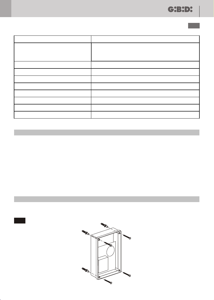
INSTALLATION
Use glands adequate to ensure proper mechanical connection of cable and maintain the box protection degree IP55.
(2).
2
Page 5

10
F4 PLUS
UK
INSTALLATION WARNINGS
• Before proceeding with installation, fit a magnetothermal or differential switch with a maximum capacity of 10A
upstream of the system. The switch must guarantee omnipolar separation of the contacts with an opening
distance of at least 3 mm.
• To prevent possible interference, differentiate and always keep the power cables (minimum cross-section
1.5 mm²) separate from the signal cables (minimum cross-section 0.5 mm²).
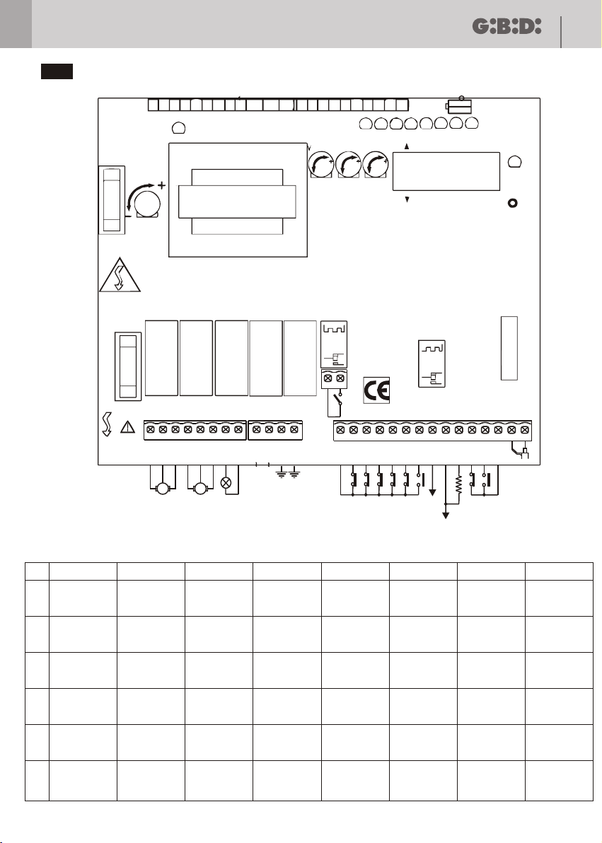
• Make the connections referring to the following tables and to the attached screen-print. Be extremely careful to
connect in series all the devices that are connected to the same N.C. (normally closed) input, and in parallel all
the devices that share the same N.O. (normally open) input. Incorrect installation or improper use of the
product may compromise system safety.
• Keep all the materials contained in the packaging away from children, since they pose a potential risk.
• The manufacturer declines all responsibility for improper functioning of the automated device if the original
components and accessories suitable for the specific application are not used.
• After installation, always carefully check proper functioning of the system and the devices used.
• This instruction manual addresses persons qualified for installation of "live equipment". Therefore, good
technical knowledge and professional practice in compliance with the regulations in force are required.
• Maintenance must be carried out by qualified personnel.
• Before carrying out any cleaning or maintenance operation, disconnect the control unit from the mains.
• This control unit may only be used for the purpose for which it was designed.
• Check the aim of the final use and make sure that all safety measures are taken.
• Use of the product for purposes different from the intended use has not been tested by the manufacturer,
therefore any work is carried out on full responsibility of the installer.
• Mark the automated device with visible warning plates.
• Warn the user that children or animals may not play or stand around near the door.
• Appropriately protect the danger points (for example, using a sensitive frame).
WARNINGS FOR THE USER
In the event of an operating fault or failure, cut the power upstream of the control unit and call Technical Service.
Periodically check functioning of the safety devices. Any repairs must be carried out by specialised personnel
using original and certified materials.
The appliance is not to be used by children or people with reduced physical, sensory or mental capabilities, or
lack of experience and knowledge, unless they have been given supervision or instruction.
Do not touch the card for adjustments and/or maintenance.
WARNING: IMPORTANT SAFETY INSTRUCTIONS.
It is very important to follow the present instructions for your own safety.
Please keep this manual.
Page 6
F4 PLUS
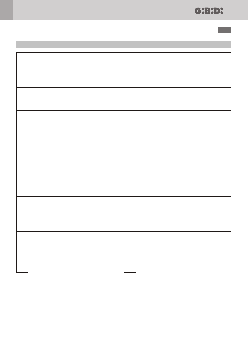
ELECTRICAL CONNECTIONS: TERMINAL BOARDS
11
UK
Output - OPENS motor 1
1
(motor to be used for pedestrian gate) *
COMMON output - motor 1
2
(motor to be used for pedestrian gate) *
Output - CLOSES motor 1
3
(motor to be used for pedestrian gate) *
Output – OPENS motor 2
4
COMMON output - motor 2
5
Output – CLOSES motor 2
6
IF DIP 9 OFF = PHASE output for COURTESY
LIGHT (+2 minutes after run time)
7
IF DIP 9 ON= Fixed output
for FLASHLIGHT code 70106
IF DIP 9 OFF = NEUTRAL output for
COURTESY LIGHT (+2 minutes after run time)
8
IF DIP 9 ON= Fixed output
for FLASHLIGHT code 70106
9
LINE INPUT 230 V ~ NEUTRAL
LINE INPUT 230 V ~ PHASE
10
GROUND
11
GROUND
12
COMMON for FA1-FC1-FC2-FA2- inputs
13
of PHOTOCELL
LIMIT SWITCH input - closes motor 2 (NC)
14
LIMIT SWITCH input-opens motor 2 (NC)
15
LIMIT SWITCH input-closes motor 1(NC)
16
LIMIT SWITCH input-opens motor 1 (NC)
17
PHOTOCELL input (NC)
18
START input (NO)
19
24 Vac output for power supply of
PHOTOCELLS and ACCESSORIES (max. 8W)
20
(2 pair of photocells + radio receiver)
Common output (0 Vac) for power supply of
PHOTOCELLS, ACCESSORIES and
21
ELECTRIC LOCK
12 Vac output for ELECTRIC LOCK (max. 15W)
22
STOP input (NC; if not used connect with
23
jumper to terminal 25)
Input for PEDESTRIAN GATE START
24
(NA, acts on motor 1)
COMMON input for STOP-START-START
25
PEDESTRIAN GATE
ANTENNA CORE input
26
ANTENNA BRAID input
27
Relay clean-contact to:
- connect a flashlight with fixed light (code
70107) drawing power from the terminals 7 and
28
8 (the relay flashes fast during opening and
-
slowly during closing). Control a warning light
29
to signal gate movement.
- connect a 24 Vac lamp powered by terminals
20-21 (max. 1Watt)
The motor capacitor is connected between terminals 1-3 (Motor 1) and 4-6 (Motor 2).
* If the system controls a double-gate system with phase shift (V3 turned clockwise), motor 1 starts opening two
seconds before motor 2, while during closing it starts the mouvement with the delay set by adjusting trimmer
V3.
Page 7
12
UK
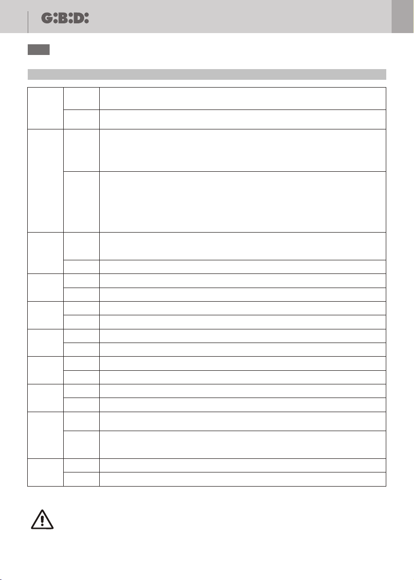
PROGRAMMING FUNCTIONS (DIP SWITCH)
When the photocell is intercepted, both during opening and closing, the gate motion is
ON
DIP1
DIP2
DIP3
DIP4
DIP5
DIP6
DIP7
DIP8
DIP9
DIP10
OFF
OFF
OFF
OFF
OFF
OFF
OFF
OFF
OFF
OFF
locked until the photocell is freed. Subsequently, there is always an opening phase.
The photocell stops and immediately inverts the motion of the gate during the closing
phase, while during opening it is uninfluential.
Enables the CONDOMINIUM function, i.e. one START command opens the gate, and no
other START commands are accepted during opening. During PAUSE, one START
command reloads the pause time. During closing, one START command reopens the
ON
gate.Reclosing occurs only in automatic mode after the pause time, also when V4 is on
minimum.
Enables the STEP-BY-STEP functions (one START command OPENS, a second
command STOPS, a third command CLOSES the gate) or STEP-BY-STEP with
AUTOMATIC RECLOSING depending on how trimmer V4 is positioned:
• If turned completely anticlockwise = STEP-BY-STEP
• If turned clockwise = STEP-BY-STEP with RECLOSING i.e. after the pause time it
recloses automatically. To close with the remote control during the pause, two start
commands must be given (the first command sets the gate to STOP).
Enables the WATER HAMMER function - exercises a brief thrust during closing before
opening, facilitating release of the electric lock (if the limit switches are used, this
ON
function is disabled)
Disables the WATER HAMMER function
Cuts out limit switch input - opens motor 1
ON
Enables the opening limit switch input motor 1
Cuts out limit switch input - closes motor 1
ON
Enables the closing limit switch input motor 1
Cuts out limit switch input - opens motor 2
ON
Enables the opening limit switch input motor 2
Cuts out limit switch input - closes motor 2
ON
Enables the closing limit switch input motor 2
Cuts out photocell input
ON
Enables the photocell input
The outputs 7-8 of the terminal board are used to control a FLASHLIGHT equipped
ON
with its own flashing circuit (code 70106)
The outputs 7-8 of the terminal board become outputs for the COURTESY LIGHT and
remain active for 3 minutes after the run time (max. 100W). In this mode the terminals
28-29 can be used to connect a flashlight without flashing circuit.(code 70107)
ON
NOT USED
NOT USED
F4 PLUS
In the event of a system with only one motor and using the limit switches, the dip switches 4, 5,
6 and 7 must all be set to OFF, while if using only one type of limit switch, e.g. Fa1 and/or Fa2,
enable (OFF position) only the corresponding dip switch.
Page 8
F4 PLUS
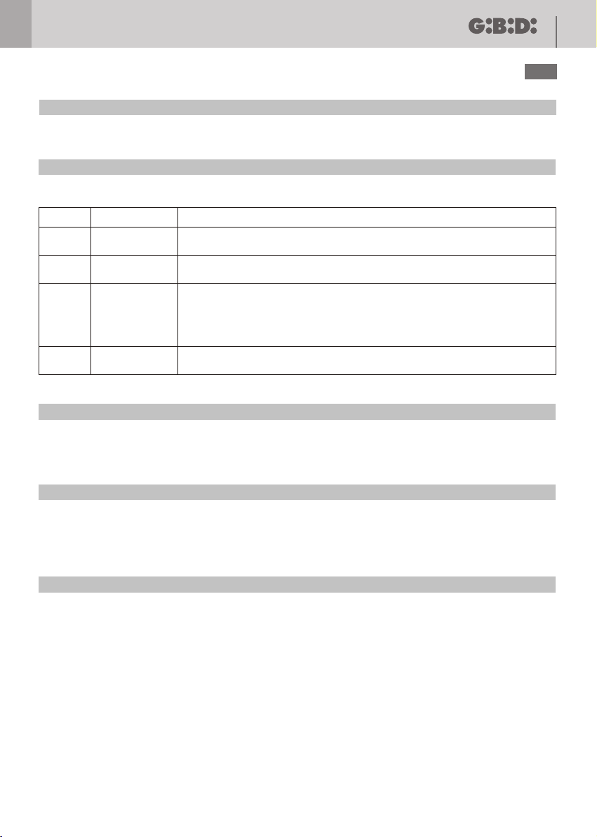
DEFAULT SETTINGS (DIP SWITCH)
DIP SWITCHES 1, 2, 3, 9, 10 OFF; DIP SWITCHES 4, 5, 6, 7, 8 ON
TRIMMER ADJUSTMENT
There are 4 trimmers (V1-V2-V3-V4) on the F4PLUS control unit to adjust the following:
13
UK
TRIMMER
V1
V2
V3
V4
FUNCTION DESCRIPTION
FORCE
RUN TIME
PHASE SHIFT
TIME
PAUSE TIME
Turned clockwise it adjusts the motor torque from 40% to 98%.
For the first 3 seconds pickup occurs.
Turned clockwise, it adjusts the RUN TIME from 2 to 100 seconds.
Turned clockwise, it adjusts the delay time between the start of the closing
mouvement of motor 2 and the start of the closing of motor 1 (from 0 to 20
seconds). The phase shift during opening is fixed at 2 seconds. With V3 set to
minimum the delays are cancelled both during opening and closing
double sliding gate version) and the WATER HAMMER function is disabled.
Turned clockwise it adjusts the PAUSE TIME from 2 to 100 seconds. Adjusted
to minimum, it disables the pause time = STEP-BY-STEP function.
DEFAULT SETTINGS
Trimmer V1 adjusted to maximum.
Trimmers V2, V3 and V4 adjusted to half their travel.
FINAL CHECKS AND TESTING
Before powering the control unit, check the following:
1) Check that the dip switches and trimmers have been set properly according to requirements.
2) Check the electrical connections; Improper connection may cause damage to the control unit and the operator.
POWER THE DEVICES
3) Check that the red LEDs of the safety devices are on and the yellow LEDs off
4) Check that when engaging any limit switches used the corresponding LEDs come on.
5) Check that when passing through the beam of the photocells the corresponding LED goes off.
6) Check that the motors are locked and ready for operation. Remove any obstacles from the operating range of the
gate, then give the START command. Upon the first command, the control unit starts an opening phase; check that
the motor rotation direction is correct.
6) If not, invert the wires of terminals 1-3 and/or 4-6.
7) Fine adjust the trimmers.
Page 9
14
F4 PLUS
UK
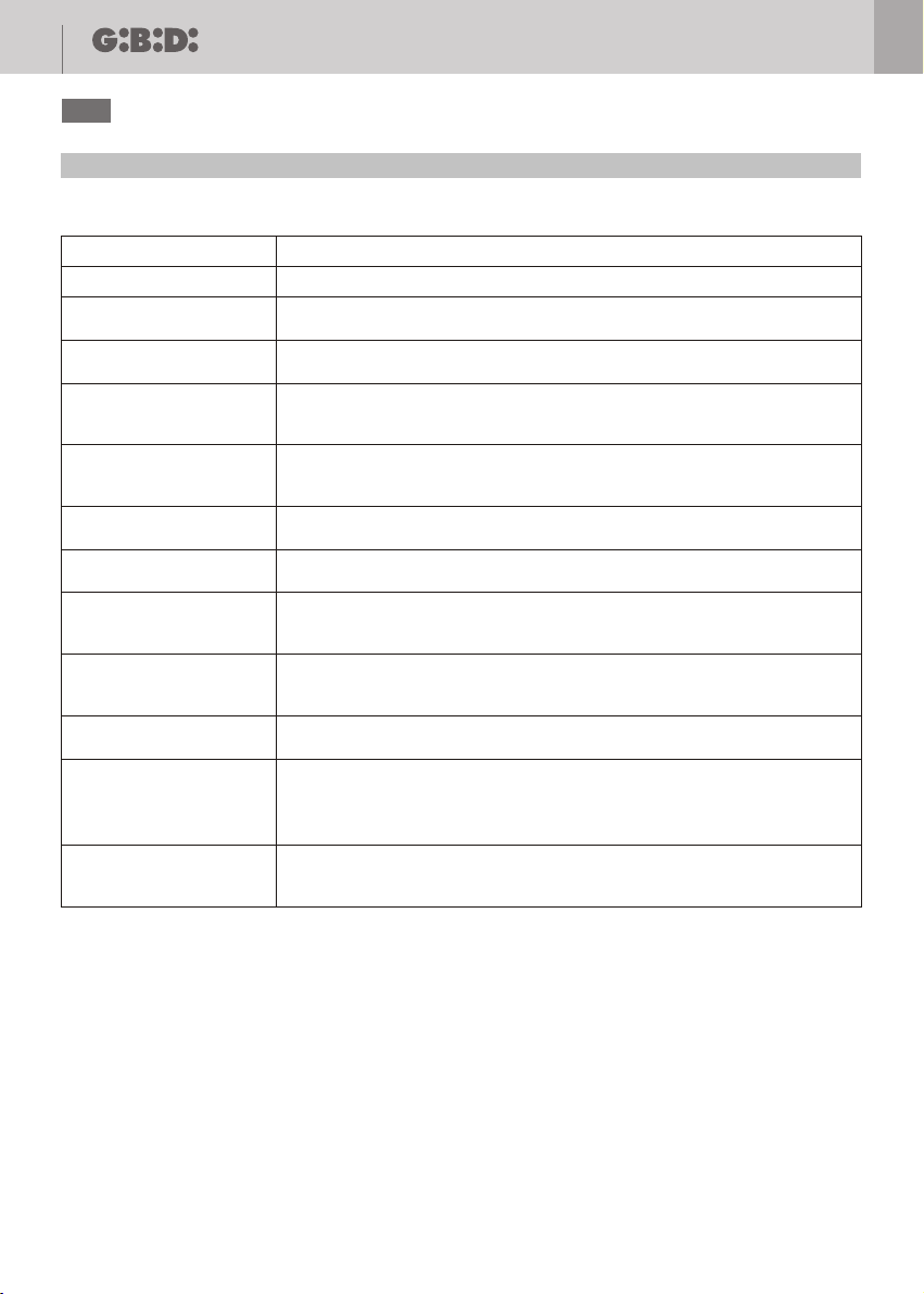
TROUBLESHOOTING
Before any installation or maintenance operation, ensure that the power supply has been disconnected.!!
FAULT POSSIBLE CAUSES and SOLUTIONS
Red 24 Vac LED off
The operator does not
open or reclose
The flashlight is on but the
gate does not move.
Red LEDs
FA1-FC1-FA2-FC2PHOTOCELL off
Red STOP LED off
Yellow LEDs always on
After the run time the gate
does not reclose
After the motors have stopped,
the flashlight connected to
terminals 7-8 does not go off.
Upon starting the gate
does not execute the water
hammer.
The gate does not perform a
phase shift when it starts
The transmitter has a
small range
The card does not learn
the TX code
Check the 230 Vac power supply and the relevant fuse F1(5A)
Check that the red LEDs are on (except the LED of the limit switch active at
that moment) and the yellow ones off.
Start has been pressed with the photocells engaged. Check that the photocells
are not engaged; once released the gate will start moving.
Check that the relevant inputs and safety switches are connected
(FA1-FC1-FA2-FC2-PHOTOCELL) or the relevant DIP SWITCH set to ON.
Check the fuse F2 (0.16A).
Check that the STOP input is connected to an NC button or that a jumper has been
connected between the terminals 23 and 25 (WARNING: the STOP intervention
causes a functional stop and NOT a safety stop).
Check that the START and PEDESTRIAN GATE inputs have been connected
to NO buttons.
Check that the trimmer V4 (Pause) is not turned completely anticlockwise.
Check that DIP9 is set to ON. If only 2 limit switches are used, the relevant
DIP SWITCHES must set to OFF, the other 2 to ON.
Check that DIP3 is set to ON and check that TRIMMER V3 is not on 0.
Check that the trimmer V3 (closing delay) is not turned completely anticlockwise.
Check that the antenna has been positioned properly (braid terminal 26, core terminal
27,if a built-in radio or AU01630N receiver is used) (if an AU01710 plug-in receiver is
used, the antenna must be connected to the terminals on the receiver).
Check that there are no sources of disturbances in the vicinity which limit the range.
Check the maximum number of codes that can be stored (200). Check if remote
controls of the same family as the first are being learned: DIP SWITCH or ROLLING.
Check that the frequency of the radio control is the same as the receiver.
Page 10
F4 PLUS
CE Declaration of conformity
The manufacturer:
GI.BI.DI. S.r.l.
Via Abetone Brennero, 177/B,
46025 Poggio Rusco (MN) ITALY
Declares that the products:
ELECTRONIC CONTROL UNIT F4 PLUS
are in conformity with the following CEE Directives:
LVD Directive 2006/95/CE and subsequent amendments;
•
• EMC Directive 2004/108/CE and subsequent amendments;
and that the following harmonised standards have been applied:
• EN60335-1,
• EN61000-6-2, EN61000-6-3
15
UK
Date 30/07/08
Managing Director
Oliviero Arosio
Page 11

Cod. AIC1071 - 07/2008 - Rev. 00
GI.BI.DI. S.r.l.
Via Abetone Brennero, 177/B
46025 Poggio Rusco (MN) - ITALY
Tel. +39.0386.52.20.11
Fax +39.0386.52.20.31
E-mail: [email protected]
Numero Verde: 800.290156
w w w . g i b i d i . c o m
 Loading...