

Page 1

BL240
BL240 - (15400)
Operatore elettromeccanico lineare
ISTRUZIONI PER L’INSTALLAZIONE
Electromechanical linear operator
INSTRUCTIONS FOR INSTALLATIONS
I UK F E
D P NL GR
Page 2

2
BL240
1a
5
10
91b
8
10
7
4
1
A
3
2
9
B
5
8
A
9
1
2
3a
3b
4a
4b
BL240 - 24Vdc
DESCRIZIONE CAVI / CABLES DETAILS
Rosso / Red
1
Nero / Black
2
3a
Blu / Blue
Marrone / Brown
3b
4a
Blu / Blue
4b
Marrone / Brown
6
Positivo / Positive
Negativo / Negative
FCA OPEN
FCA COM
FCC CLOSE
FCC COM
BL240 - 24Vdc
cavo nero / black cable
cavo rosso / red cable
- MOTORE / - MOTOR
+ MOTORE / + MOTOR
guaina bianca / white sheath
FCA OPEN
FCA COM
FCC COM
FCC CLOSE
guaina nera / black sheath
Page 3

BL240
2
85 78
3
151 mm
740 mm
93
A
a1>60
B ≥ 140 per β = 110°
B > 60+d1 per β = 90°
C
Cu
897 mm
109 mm
d1
D ≥ 90
β
E=60
Page 4

4
4 5
6 7
A
A
100/120
150150
10
0/1
2
0
B
B
BL240
E=60
8 9
Page 5

BL240
10 11
5
141312
15a 15b
A
A
B
B
Page 6
6
BL240
15c
b
c
a
17 18
16
19a
19b
Page 7
BL240
20
7
7
6
4
1
21
2
5
3
7
4
6
5
3
4
2
1
3
5
Page 8

BL240
UK
INTRODUCTION
The BL240 operator for swing gates is an electromechanical device that transmits motion to the gate by means of a
worm screw. It is locked when the motor is not running, and it is therefore not necessary to install locks for leafs up to
2 m.
INSTALLATION WARNINGS
• Before proceeding with installation, fit a magnetothermal or differential switch with a maximum capacity of 10A
upstream of the system. The switch must guarantee omnipolar separation of the contacts with an opening
distance of at least 3 mm.
• Keep all the materials contained in the packaging away from children, since they pose a potential risk.
• The manufacturer declines all responsibility for improper functioning of the automated device if the original
components and accessories suitable for the specific application are not used.
• After installation, always carefully check proper functioning of the system and the devices used.
• This instruction manual addresses professionals qualified to install “live equipment” and therefore requires good
technical knowledge and installation in compliance with the regulations in force.
• Maintenance must be carried out by qualified personnel.
• Before carrying out any cleaning or maintenance operation, disconnect the control unit from the mains.
• This product has been designed and constructed exclusively for the use indicated in this documentation. Any
other use may cause damage to the product and be a source of danger.
• Check the intended end use and take all the necessary safety precautions.
• Use of the product for purposes different from the intended use has not been tested by the manufacturer,
therefore any work is carried out on full responsibility of the installer.
• Mark the automated device with visible warning plates.
• Warn the user that children or animals should not play or stand near the gate.
• Appropriately protect the danger points (for example, using a sensitive frame).
• Check proper installation of the earthing system. connect all the metal parts of doors, gates, etc. and all the
system components to an earth terminal.
• Exclusively use original spare parts for any maintenance or repair operations.
• Do not modify any components of the automated device unless expressly authorised by Gi.Bi.Di.
15
Use suitable cable clamps to ensure that the wiring is properly connected mechanically and such that an IP44
degree of protection is maintained.
WARNINGS FOR THE USER
In the event of an operating fault or failure, cut the power upstream of the control unit and call Technical Service.
Periodically check functioning of the safety devices. Any repairs must be carried out by specialised personnel using
original and certified materials.
The product may not be used by children or persons with reduced physical, sensorial or mental capacities, or lacking
experience and knowledge, unless appropriately instructed.
Do not access the circuit board for adjustments and/or maintenance.
CAUTION: IMPORTANT SAFETY INSTRUCTIONS.
It is important to follow these instructions in order to safeguard persons.
Keep this instruction booklet
Page 9

16
BL240
UK
ELECTRICAL EQUIPMENT
Electric system setup
Set up the electric system as shown (1a - 1b) referring to the electric system regulations and other national
regulations in force. Keep the mains power connections clearly separated from the service connections (photocells,
sensitive frames, control devices, etc.).
The main components are:
1- Antenna; screened coaxial cable
2- Electronic control unit container
3- Electric lock; 1 mm² 2-core (2x1) cable
4- Key selector; 0,5 mm² 3-core (3x0,5) cable
5- 24Vdc operators:
- 1,5 mm² 2-core (2x1,5) cable power supply RED = + BLACK = -
for a cable length of 6 m max., over it’s necessary increase the cable section.
Cable with WHITE sheath for OPENING limit switch
Cable with BLACK sheath for CLOSING limit switch
6- Omnipolar magnetothermal switch with minimum contact opening of 3 mm
220-230V/50-60Hz control unit power line: min. 1,5 mm² 3-core cable (3x1,5)
(adhere to the regulations in force)
7- 24V flashing light; 0,75 mm² 2-core (2x0,75) cable
8- Connector blocks
9- Photocell transmitter; 0,5 mm² 2-core (2x0,5) cable
10- Photocell receiver; 0,5 mm² 4-core (4x0,5) cable
CAUTION: It is important that an omnipolar magnetothermal switch with a minimum contact
opening of 3 mm be fitted upstream of the control unit.
Page 10
BL240
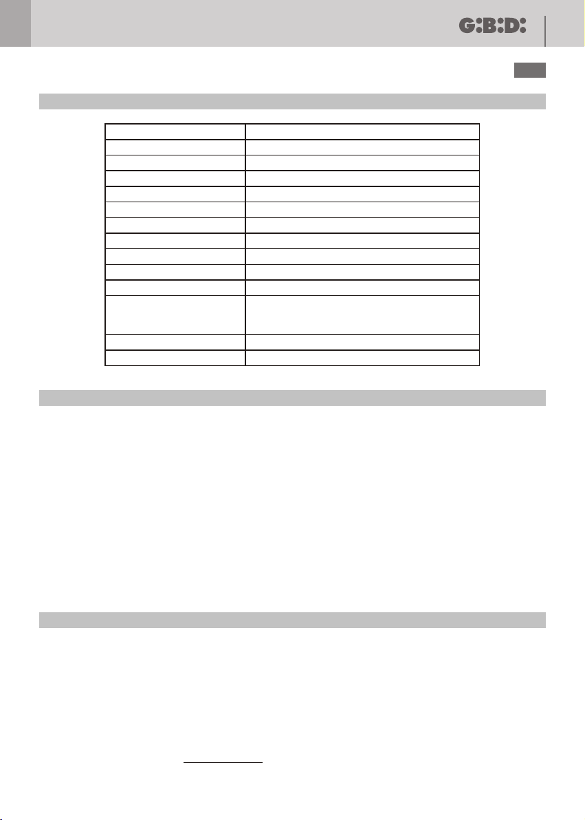
TECHNICAL DATA
17
UK
Operator
Type
Supply voltage
Power absorbed
Current absorbed
Electric motor
Useful travel
Max thrust/traction force
Operating temperature
Degree of protection
Frequency of use (%)
Maximum leaf length
Limit switch
Linear velocity
Irreversible electromechanical with worm screw
1000N (electronically adjustable)
(if fitted on blind/flush panel doors, or longer than 2,5 m
it is advisable to use an electric lock)
BL240
24 Vdc
100 W (~1000 N)
4 A (~1000 N)
24 Vdc 3000 rpm
320 mm
-20°C + 60°C
IP 44
intensive
3,5 m
2 FC (open/close)
20 mm/s
PRELIMINARY WARNINGS
Check that the gate structure is in conformity with the regulations in force and that the gate movement is linear
without friction.
Preliminary checks:
• Check that the gate structure is sufficiently robust.
• In any event, the actuator must push the leaf at a reinforced point.
• Manually check that the leafs move without force along their entire travel.
• Check that the gate opening and closing end-stops A-B(1a) have been installed.
• If the gate is not a new installation, check the state of wear of all the components, and repair or replace the
defective or worn parts.
The reliability and safety of the automated device is directly dependent on the condition of the gate structure.
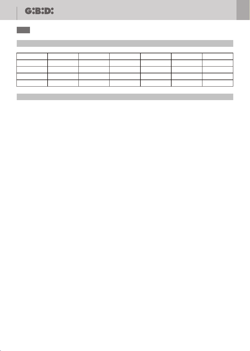
INSTALLATION DIMENSIONS (3)
If it is not possible to maintain the dimensions indicated in Table A, consider the following to calculate different
measurements:
- For β=90° A+B = Cu
- For β>90° A+B<Cu (β Max 110°)
- Dimension A must always be greater than the sum of the dimension D+d1
- In the case of a very thick leaf where it is difficult to respect dimension D, it can be increased; it is advisable to apply
the same increase to dimension A, however, respecting the rules mentioned above
The difference between A and B must not exceed 50 mm; greater differences cause irregular gate movement
(the traction/thrust force and the movement speed vary during the manoeuvre).
Page 11
18
UK
Table A - for 100 mm column and 50 mm leaf thickness
BL240
β
90°
90°
100°
110°
A
140
150
140
120
B
125
150
140
140
C
725
731
730
730
D
100
100
90
90
60
60
60
60
E
Cu
265
300
302
300
OPERATOR INSTALLATION
Preliminary checks:
For proper functioning of the automated device, the existing or new gate structure must meet the following
requirements:
- The individual leafs must have a maximum length of 3,5 metres
- The leaf structure must be robust and rigid
- The leafs must move smoothly and uniformly without irregular friction along their entire travel
- The existing hinges must be in a good condition
- The mechanical end-stops A-B(1a) must be fitted
Installing the operators
1 - Find the most suitable point where to fasten the front bracket of the operator (4) and mark it.
2 - Using a spirit level mark the point on the pillar where to fasten the rear bracket (4).
3 - Identify the point where to fasten the rear bracket in relation to the dimensions A-B and E (5).
CAUTION: Where there are big pillars or walls, a niche (6) must be made so that the dimensions A,B,and D are
respected.
Fastening the rear bracket:
- If it is an iron pillar weld on the bracket check the column thickness and if it is less than 5 mm make a
reinforcement plate of such dimensions that the welds are made on the column rib (7).
- If it is a cement pillar, make a plate of 5 mm thick with 4 holes. Weld the bracket in the centre of the
plate and secure everything with through screws.
4 - Power the operator, move the lead nut forward to about 5-10 mm from the mechanical end-stop.
WARNING: when you feed the operator not installed on the gate, do not force the nut screw on the mechanical
limit switches to avoid damages to the operator. Stop the operator movement some millimetres
before the contact with the mechanical limit switch.
5 - Fasten the front bracket on the operator (9).
6 - Move the leaf to closed position against the mechanical end-stops and secure it with a clamp.
7 - Fit the operator on the rear bracket using the pin provided (10).
8 - Rest the front bracket on the point marked in step 1 above, then use a spirit level to check that the operator is
perfectly level, and mark the exact fastening point for the front bracket (4 - 5).
9 - Remove the operator from the rear bracket.
10 - Remove the front bracket from the operator.
11 - Fasten the front bracket at the point marked.
Fastening the front bracket:
- If it is an iron gate weld on the bracket check the thickness of the pipe on which the bracket is to be welded and
if it is less than 5mm make a reinforcement plate of such dimensions that the welds are made on the pipe rib
(11).
Page 12

BL240
UK
- If the gate is in a material different from iron, make a plate of 5 mm thick with 4 holes. Weld the bracket in the
centre of the plate and secure everything with through screws (12).
12- Unlock the operator (see unlocking device).
13 - Fit the operator on the brackets.
14 - Manually open and close the gate to its full opening and closing travel. The gate must move smoothly without
friction and the lead nut must not reach the mechanical end-stop during opening or closing. If otherwise, adjust
the bracket positions.
It is recommended to leave at least 40-50 mm of cable free.
LIMIT SWITCH ADJUSTMENT
- Cut the power to the system.
- Undo the retaining screws of the front flange (13) and remove it (14).
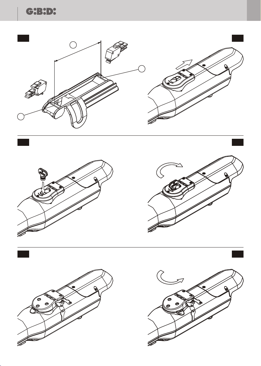
- Using a no. 8 box wrench, turn the screws (15) to adjust the opening limit switch A(15) and the closing limit switch
B(15), respectively.
The right-hand screw adjusts the closing limit switch and the left-hand one the opening limit switch (15a - 15b).
The deceleration stroke made by the operator is determined by the distance between the ends of the cam present on
the nut screw b(15c), where there are some relieves a/c(15c) for micro switches activation, this distance is fixed on
the operator.
On the contrary the stroke in deceleration visible on the leaf is proportional to the relation between the quota b(15c)
and the working stroke of the operator Cu(3). Therefore the lowest is the working stroke Cu(3) used to open/close the
leaf, the longest is the way in deceleration.
UNLOCKING DEVICE
Manual operation
If the gate needs to be operated manually because of a power failure or operator malfunctioning, move the protection
cap (16) in the direction indicated by the arrow (16) and insert the key provided in the lock (17).
Turn the key 90° in the direction indicated by the arrow stamped on the unlocking device; the operator will stay
unlocked without having to hold the key in position.
Manually open and close the leafs.
To prevent the gate from moving in the wind or because it is unbalanced, it is advisable to relock the operator after the
manual emergency manoeuvre by turning the key 90° in the opposite direction indicated by the arrow stamped on
the unlocking device (18).
Remove the key and then slightly move the gate until the operator locks.
- Move the gate manually only in the event of a power failure.
19
OPTIONAL UNLOCKING DEVICE
Manual operation
If the gate needs to be operated manually because of a power failure or operator malfunctioning, lift one of the
protection caps on the sides (19a), and insert the key provided in the lock (19a).
Turn the key 180° anticlockwise (19b) and turn the unlocking slider 90° anticlockwise; the operator will stay
unlocked without having to hold the device in position.
Manually open and close the leafs.
To prevent the gate from moving in the wind or because it is unbalanced, it is advisable to relock the operator after the
manual emergency manoeuvre by turning the unlocking slider 90° clockwise (19b). The operator is relocked
when the cursor is positioned in longitudinal direction.
Turn the key 180° clockwise and remove it (the key can only be removed from one position), then slightly move
the gate until it locks.
- Move the gate manually only in the event of a power failure.
Page 13

20
UK
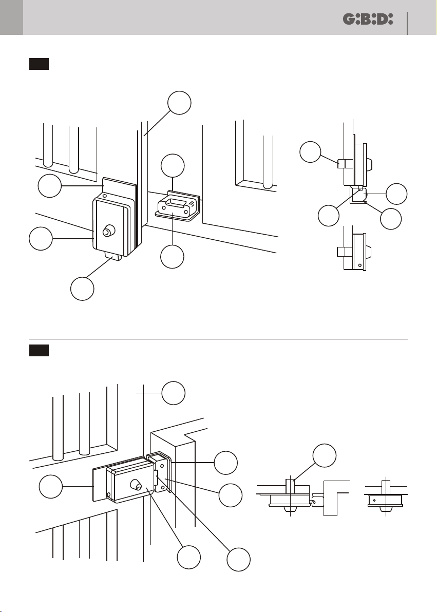
INSTALLING THE ELECTRIC LOCK
If you need to install an electric lock, refer to figures (20) and (21)
1) ELECTRIC LOCK
2) ELECTRIC LOCK FASTENING PLATE
3) BUSHING
4) END-STOP FOR BUSHING
5) SPRING LATCH
6) THROUGH CYLINDER (ON REQUEST)
7) GATE
FINAL CHECKS
Power the system and run a complete opening and closing cycle checking that:
• The safety devices function properly;
• The gate moves smoothly;
• Good hold of the fastening brackets;
• That the power cable moves freely;
• The gate assembly conforms to EN 12453 and EN 12445;
• For further details and information on the reference standards, visit our site: www.gibidi.com
MAINTENANCE
BL240
Periodically check the gate structure, in particular:
- Check functioning of the hinges;
- Check that the leafs are correctly balanced. Excessive inclination of the leafs will result in faster wear of the
operator fastening brackets. Do the test by unlocking the operator and checking that the leafs do not move on their
own;
- Check good functioning of the safety devices;
- Unlock the operator and check that there are no points of friction along the entire travel;
- Check that there is no dirt or debris on the worm screw, and if so, clean and then lubricate the worm screw with
lubricating grease.
- Periodically check proper adjustment of the operator thrust force and the efficiency of the unlocking device for
manual operation (see the relative paragraph).
- The safety devices installed on the system must be checked every six months.
Gi.Bi.Di. Srl reserves the right to change the technical data without prior notice in relation to product development.
MALFUNCTIONING
For any unresolved malfunction, cut the power to the system and call in a qualified technician (installer). In the
period when the gate is out of service, activate the manual unlocking device to allow manual opening and
Page 14

BL240
21
UK
CE Declaration of conformity
The manufacturer:
GI.BI.DI.
S.r.l.
Via Abetone Brennero, 177/B,
46025 Poggio Rusco (MN) ITALY
Declares that the products:
ELECTROMECHANICAL LINEAR OPERATORS BL240
Are in conformity with the following CEE Directives:
• EMC Directive 2004/108/CE and subsequent amendments;
and that the following harmonised standards have been applied:
• EN61000-6-1, EN61000-6-3
Data 20/03/09
Managing Director
Oliviero Arosio
Page 15

Cod. AIC6512 - 03/2009 - Rev. 00
GI.BI.DI. S.r.l.
Via Abetone Brennero, 177/B
46025 Poggio Rusco (MN) - ITALY
Tel. +39.0386.52.20.11
Fax +39.0386.52.20.31
E-mail: [email protected]
Numero Verde: 800.290156
w w w . g i b i d i . c o m
 Loading...