


FLOOR
FLOOR (810 - 812) Operatore oleodinamico
ISTRUZIONI PER L’INSTALLAZIONE
Hydraulic Operator
INSTRUCTIONS FOR INSTALLATIONS
I IF UK D
E DP NL

2
PREDISPOSIZIONI ELETTRICHE
APPAREILLAGES ELECTRIQUES
ELECTRICAL CONNECTIONS
EQUIPOS ELECTRICOS
EQUIPAMENTO ELÉCTRICO
ELEKTROAUSSTATTUNG
ELEKTRISCHE AANSLUITINGEN
I
1 Costole sensibili.
2 Contenitore apparecchiatura elettronica.
3 Operatori; FLOOR 810 alimentazione cavo a 4 conduttori da 1,5 mm² cadauno:
bianco= comune motore, marrone= apertura, nero= chiusura;
FLOOR 812 alimentazione cavo a 2 conduttori da 2,5 mm² cadauno.
4 Pulsantiera; cavo a 5 conduttori da 0,5 mm².
5 Selettore a chiave; cavo a 3 conduttori da 0,5 mm².
6 Linea di alimentazione all’apparecchiatura 220-230 V 50-60 Hz; cavo a 3 conduttori
da 1,5 mm² min. (attenersi alle Norme vigenti).
7 Segnalatore a luce lampeggiante; cavo a 2 conduttori da 1,5 mm².
8 Antenna.
9 Trasmettitore fotocellula; cavo a 2 conduttori da 0,5 mm².
10 Ricevitore fotocellula; cavo a 4 conduttori da 0,5 mm².
11 Elettroserratura.
ATTENZIONE: è importante che sulla linea di alimentazione venga installato, a monte
dell’apparecchiatura, un interruttore magnetotermico onnipolare con apertura minima
dei contatti pari a 3 mm.
F
1 Barres palpeuses.
2 Boîtier de la platine électronique.
3 Opérateurs; FLOOR 810 alimentation par câble à 4 conducteurs de 1,5 mm
cun: blanc= commun moteur, brun= ouverture, noir= fermeture; FLOOR 812
alimentation par câble à 2 conducteurs de 2,5 mm
4 Tableau de commande; câble à 5 conducteurs de 0,5 mm
5 Sélecteur à clé; câble à 3 conducteurs de 0,5 mm
6 Ligne d’alimentation de la platine 220-230 V 50-60 Hz; câble à 3 conducteurs de
2
mini (respecter les normes en vigueur).
1,5mm
7 Clignotant; câble à 2 conducteurs de 1,5 mm
8 Antenne.
9 Emetteur cellule photo-électrique; câble à 2 conducteurs de 0,5 mm
10 Récepteur cellule photo-électrique; câble à 4 conducteurs de 0,5 mm
11 Electroserrure.
ATTENTION: Sur la ligne d’alimentation, en amont de la platine, il est important de
monter un interrupteur magnétothermique omnipolaire ayant une ouverture des contacts
minimale de 3 mm.
2
.
2
chacun.
2
.
2
.
2
cha-
2
.
2
.
UK
1 Sensitive frame.
2 Electronic equipment container.
3 Operators; FLOOR 810 power supply, cable with 4 conductors oF 1.5 mm² each
white= motor common, brown= opening phase, black= closing phase
power supply, cable with 2 conductors oF 2.5 mm² each.
4 Push-button panel; cable with 5 conductors of 0.5 mm².
5 Key-selector; cable with 3 conductors of 0.5 mm².
6 Power supply line to equipment 220-230V 50-60Hz, cable with 3 conductors of min.
1.5 mm² (follow regulations in force).
7 Flashing light; cable with 2 conductors of 1,5 mm².
8 Antenna.
9 Photocell transmitter; cable with 2 conductors of 0.5 mm².
10 Photocell receiver; cable with 4 conductors of 0.5 mm².
11 Electric lock.
WARNING: It is important that an omnipolar magneto-thermal switch with a contact
opening of minimum 3 mm is installed on the power supply line, upstream of the
equipment.
; FLOOR 812
E
1 Bandas sensibles.
2 Contenedor del equipo electrónico.
3 Operadores; FLOOR 810 alimentación por cable de 4 conductores de 1,5 mm²
c/u: blanco= comun del motor, marrón= abertura, negro= cierre; FLOOR 812
alimentación por cable de 2 conductores de 2,5 mm² c/u.
4 Botonera; cable de 5 conductores de 0,5 mm².
5 Selector de llave; cable de 3 conductores de 0,5 mm².
6 Línea de alimentación al equipo 220-230 V 50-60 Hz; cable de 3 conductores de
1,5 mm² (mínimo) (atenerse a las normas vigentes).
7 Destellador; cable de 2 conductores de 1,5 mm².
8 Antena.
9 Fotocélula transmisora; cable de 2 conductores de 0,5 mm².
10 Fotocélula receptora; cable de 4 conductores de 0,5 mm².
11 Electrocerradura.
ATENCIÓN: es importante instalar en la línea de alimentación, antes del equipo, un
interruptor magnetotérmico omnipolar con abertura mínima de los contactos igual a
3 mm.
:

3
P
1 Costa sensível.
2 Invólucro aparelhagem electrónica.
3 Operadores: FLOOR 810 alimentação cabo de 4 condutores de 1,5 mm² cada:
branco= comun do motor, castanho= abertura, preto= encerramento; FLOOR
812 alimentação cabo de 2 condutores de 2,5 mm² cada.
4 Caixa de comandos: cabo de 5 condutores de 0,5 mm².
5 Selector de chave: cabo de 3 condutores de 0,5 mm².
6 Linha de alimentação da aparelhagem 220 - 230 V 50-60 Hz; cabo de 3 condutores
de 1,5 mm² (respeitar as normas em vigor).
7 Lâmpada pisca-pisca; cabo de 2 condutores de 1,5 mm².
8 Antena.
9 Transmissor fotocélula: cabo de 2 condutores de 0,5 mm².
10 Receptor fotocélula: cabo de 4 condutores de 0,5 mm².
11 Fechadura eléctrica.
ATENÇÃO: é importante que a na linha de alimentação, a montante da aparelhagem,
seja instalado um interruptor magnetotérmico omnipolar com abertura mínima dos
contactos de 3 mm.
D
1 1 Kontaktschienen
2 Steuergerätgehäuse
3 Antriebe: FLOOR 810 Versorgung durch Kabel mit 4 Leitern mit je 1,5 mm
weiß = gemeinsam Motor, braun = Öffnung, schwarz = Schließung;
FLOOR 812 Versorgung 2-Leiter-Kabel 2,5 mm
4 Druckknopftafel: 5-Leiter-Kabel 0,5 mm
5 Schlüsselschalter: 3-Leiter-Kabel 0,5 mm
6 Versorgungsleitung zum Steuergerät 220-230 V, 50-60 Hz; 3-Leiter-Kabel 1,5
7 Blinklicht: 2-Leiter-Kabel 1,5 mm
2
(geltende Vorschriften befolgen).
mm
2
8 Antenne
9 Lichtschrankensender: 2-Leiter-Kabel 0,5 mm
10 Lichtschrankenempfänger: 4-Leiter-Kabel 0,5 mm
2
2
2
2
2
11 Elektroschloss
2
:
ACHTUNG: An der Versorgungsleitung vor dem Steuergerät unbedingt einen allpoligen, thermomagnetischen Schalter mit einer Kontaktweite von mindestens 3 mm
anbringen.
NL
1 Veiligheidsstrip : 2 draden sectie 0,5 mm5
2 Elektronische sturingskast
3 Opener 220-230 V : 4 draden sectie 1,5 mm5
- witte = gemeenschappelijke motor
- bruin = openen
- zwart = sluiten
4 Drukknoppaneel : 5 draden sectie 0,5 mm5
5 Sleutelcontact : 3 draden sectie 0,5 mm5
6 Voedingskabel : 220-230 V, 50-60 Hz : 3 draden sectie 1,5 mm5 min.
(respecteer de van kracht zijnde normen).
7 Knipperlicht 220 V : 2 draden sectie 1,5 mm5
8 Antenne
9 Fotocel zender : 2 draden sectie 0,5 mm5
10 Fotocel ontvanger : 4 draden sectie 0,5 mm5
11 Elektrisch slot : 2 draden sectie 1,5 mm5
OPGELET: Het is heel belangrijk dat er een onderbrekingsschakelaar wordt geplaatst
op alle voedingsdraden. De minimum opening van deze schakelcontacten moet 3
mm. bedragen.

4
MON
TAGGIO DEGLI OPERATORI
MONTAGE DES OPERATEURS
INSTALLATION OF THE OPERATORS
MONTAJE DE LOS OPERADORES
MONTAGEM DOS MOTORES
ANTRIEBSMONTAGE
PLAATSING VAN DE OPENERS
I
1 Cassetta di fondazione autoportante (413 x 323 x 198H ).
2 Perno autoportante diametro 70.
3 Tubo in PVC diametro 60/80 per il drenaggio dell’acqua per evitare ristagni.
4 Fori diametro 40 per il passaggio del cavo elettrico di alimentazione del motore.
F
1 Boîte de fondation autoporteuse (413 x 323 x 198 H).
2 Pivot autoporteur Ø 70.
3 Tuyau de drainage en PVC Ø 60/80 pour éviter la stagnation de l’eau.
4
Trous
Ø 40 pour le passage du câble électrique alimentant le moteur.
UK
1 Self-supporting foundation box (413 x 323 x 198 H).
2 Self-supporting pin: 70 diameter.
3 PVC tube: 60/80 diameter for water drainage to prevent stagnation.
4 40-diameter openeings for electric cables motor supply.
D
1 Selbsttragender Fundamentkasten (413 x 323 x 198H).
2 Selbsttragender Zapfen mit Durchmesser 70.
3 PVC-Rohr mit Durchmesser 60/80 für Drainage zur Verhinderung von
Wasseransammlungen.
4 Öffnungen mit Durchmesser 40 als Durchlass für Stromversorgungskabel des
Motors.
ESEMPIO DI FISSAGGIO
CON SALDATURA DEL
CANCELLO SUL PERNO
AUTOPORTANTE
EXEMPLE DE FIXATION
PAR SOUDAGE DE LA
GRILLE SUR LE PIVOT
AUTOPORTEUR
EXEMPLE OF WELDING OF GATE
ON SELF-SUPPORTING PIN
EJEMPLO DE FIJACION CON
SOLDADURA DE LA PUERTA
AL PERNO AUTOPORTANTE
EXEMPLO DE FIXAÇÃO COM
SOLDADURA DO PORTÃO
NO PERNO AUTOPORTANTE
BEISPIEL FÜR TORBEFESTIGUNG
DURCH ANSCHWEISSEN AUF
SELBSTTRAGENDEN ZAPFEN.
VOORBEELD OM HET HEKKEN
AAN DE ZELFDRAGENDE DRAAIAS TE LASSEN
E
1 Cajón de fundación autoportante (412 x 323 x 198 de altura).
2 Perno autoportante Diám. 70.
3 Tubo de PVC Diám. 60/80 de drenaje agua para evitar estancamientos.
4
Agujeros de Diám. 40 para pasar el cable eléctrico de alimentación del motor.
P
1 Caixa de fundação autoportante (413 x 323 x h198).
2 Perno autoportante diâm. 70
3 Tubo de PVC diâm. 60/80 de drenagem para evitar a estagnação da água.
4 Furos diâm. 40 para a passagem do cabo eléctrico de alimentação do motor.
NL
1 Zelfdragende fundatiekast (413x323x198 H)
2 Zelfdragende draaias f 70 mm.
3 PVC buis f 60/80 voor de afwatering om waterophoping te vermijden
4 Openingen f 40 mm. voor de elektrische kabel
VISTA FRONTALE DELL’INTERNO
DELLA CASSETTA
INTERIEUR DE LA BOITE: VUE DE
FACE
FRONT INTERNAL VIEW OF BOX
VISTA ANTERIOR DEL INTERIOR
DEL CAJON
VISTA DIANTEIRA DO INTERIOR
DA CAIXA
FRONTANSICHT DES KASTENINNEREN
I
NWENDIG ZICHT VAN DE FUNDATIEKAST

5
I
ATTENZIONE
É fondamentale che il cancello venga ssato sul perno autoportante nella posizione
di chiusura vericando che la cerniera sia perfettamente in asse con il perno autopor-
tante e l’anta perfettamente a piombo, e che le due tacche di riferimento A-B siano
perfettamente allineate tra loro.
1 Cassetta di fondazione
2 Perno autoportante diametro 70
3 Cancello
4 Bronzina sinterizzata autolubricante
5 Supporto perno autoportante
6 Cerniera
A-B Tacche di riferimento
F
ATTENTION
La grille doit être obligatoirement xée par soudage sur le pivot autoporteur en position
de fermeture. S’assurer que la charnière est parfaitement alignée sur l’axe du pivot
autoporteur, que le ventail est parfaitement à plomb et que les deux encoches repères
A et B sont parfaitement alignées l’une sur l’autre.
1 Boîte de fondation
2 Pivot autoporteur Ø 70
3 Grille
4 Coussinet fritté autolubriant
5 Support du pivot autoporteur
6 Charnière
A-B Encoches repères.
E
ATENCION
Es indispensable que la puerta sea jada con soldadura al perno autoportante en la
posición de cierre, vericando que la bisagra esté perfectamente en eje con el perno
autoportante, la hoja esté a plombo y las dos muescas de referencia A-B alineadas
entre ellas.
1 Cajón
2 Perno autoportante Diám. 70
3 Puerta
4 Casquillo de bronce sinterizado autolubricante
5 soporte del perno autoportante
6 Bisagra
A-B Muescas de referencias.
P
ATENÇÃO
É muito importante que o portão seja soldado no perno autoportante na posição de
encerramento, vericando que a dobradiça esteja perfeitamente alinhada com o perno
autoportante, a folha perfeitamente a prumo e que as duas marcas de referência A-B
estejam perfeitamente alinhadas.
1 Caixa de fundação
2 Perno autoportante diâmetro 70
3 Portão
4 Casquilho sinterizado autolubricante
5 Suporte do perno autoportante
6 Dobradiça
A-B Marcas de referência
UK
WARNING
It is fundamental that the gate is soldered to the self-supporting pin in the closed position,
ensuring that the hinge is perfectly centered on the self-supporting pin and the swing
perfectly vertical, and the two centering marks A-B are perfectly aligned.
1 Fundation box
2 70-Diam. self-supporting pin
3 Gate
4 Self-lubricating sintered bushing
5 Self-supporting pin support
6 Hinge
A-B Centering marks.
D
ACHTUNG
Das Tor muss unbedingt in geschlossener Position auf dem Zapfen befestigt werden.
Dabei ist zu überprüfen, dass das Scharnier perfekt mit dem selbsttragenden Zapfen
geuchtet ist, dass der Torügel perfekt im Lot ist, und dass die beiden Markierungskerben A-B perfekt übereinstimmen.
1 Fundamentkasten
2 Selbsttragender Zapfen mit Durchmesser 70
3 Tor
4 Selbstschmierende gesinterte Bronzebuchse
5 Unterlage selbsttragender Zapfen
6 Scharnier
A-B Markierungskerben
NL
WAARSCHUWING
Het is noodzakelijk dat het hekken op de zelfdragende draaias wordt gelast in de
gesloten positie en eveneens moet het bovenste scharnier in het center liggen van de
zelfdragende draaias. Het hekken moet ook perfect verticaal staan en de markeringen
A en B moeten perfect in lijn zijn met mekaar.
1 Fundatiekast
2 Zelfdragende draaias f 70 mm.
3 Hekken
4 Zelfsmerende bronzen bus
5 Zelfdragende draaias steun
6 Scharnier
A-B Uitlijnmarkeringen
.

6
ESEMPIO DEL MONTAGGIO
DEL CANCELLO CON
L’UTILIZZO DI UNA STAFFA
AD U SALDATA SUL PERNO
AUTOPORTANTE, CHE
PERMETTE LA MESSA IN
ASSE TRA LA CERNIERA ED
IL PERNO
EXEMPLE DE MONTAGE
DE LA GRILLE AVEC UN
ENTRIER EN U SOIDE SUR
LE PIVOT AUTOPORTEUR,
QUI PERMET D’ALIGNER LA
CHARNIERE SUR LE PIVOT
VOORBEELD OM HET
HEKKEN TE INSTALLEREN
OP EEN POORTSCHOEN WELKE GELAST WORDT OP DE
ZELFDRAGENDE DRAAIAS OM
DE DRAAIAS TE CENTEREN
MET HET SCHARNIER
EXAMPLE OF GATE
INSTALLATION USING A UBRAKET SOLDERED TO THE
SELF-SUPPORTING PIN TO
CENTER HINGE AND PIN
EJEMPLO DE MONTAJE DE
LA PURTA UTILIZANDO UNA
ABRAZADERA EN “U” SOLDADA
AL PERNO AUTOPORTANTE,
QUE PERMITE LA PUESTA EN
EJE ENTRE LA BISAGRA Y EL
PERNO
EXEMPLO DE MONTAGEM DO
PORTÃO UTILIZANDO UMA
CALHA EM FORMA DE “U”
SOLDADA AO PERNO
AUTOPORTANTE, QUE
CONSINTA O ALINHAMENTO
DA DOBRADIÇA COM O PERNO
BEISPIEL FÜR DIE MONTAGE
DES TORS UNTER VERWENDUNG
EINES U-BÜGELS, DER AUF DEN
SELBSTTRAGENDEN ZAPFEN
AUFGESCHWEISST WIRD,
WO DURCH SC HARNIER UND
ZAPFEN AUSGERICHTET
WERDEN KÖNNEN.
I
ATTENZIONE
É fondamentale che la staffa che porta il cancello venga saldata sul perno autoportante
nella posizione di chiusura vericando che la cerniera sia perfettamente in asse con il
perno autoportante e l’anta perfettamente a piombo, e che le due tacche di riferimento
A-B siano perfettamente allineate tra loro.
1 Cassetta di fondazione
2 Perno autoportante diametro 70
3 Cancello
4 Bronzina sinterizzata autolubricante
5 Supporto perno autoportante
6 Cerniera
7 Staffa
A-B Tacche di riferimento
F
ATTENTION
L’étrier de support de la grille doit être obligatoirement soudé sur le pivot autoporteur en
position de fermeture. S’assurer que la charnière est parfaitement alignée sur l’axe du
pivot autoporteur, que le ventail est parfaitement à plomb et que les deux encoches
repères A et B sont parfaitement alignées l’une sur l’autre.
1 Boîte de fondation
2 Pivot autoporteur Ø 70
3 Grille
4 Coussinet fritté autolubriant
5 Charnière
6 Charnière
7 Etrier
A-B Encoches repères.
UK
WARNING
It is fundamental that the bracket holding the gate is soldered to the self-supporting pin
in the closed position, ensuring that the hinge is perfectly centered on the self-supporting
pin and the swin perfectly vertical, and the two
centering marks A-B are perfectly aligned.
1 Fundation box
2 70-Diam. self-supporting pin
3 Gate
4 Self-lubricating sintered bushing
5 Self-supporting pin support
6 Hinge
7 Bracket
A-B Centering marks.
E
ATENCION
Es indispensable que la abrazadera de la puerta sea jada con soldadura al perno
autoportante en la posición de cierre, vericando que la bisagra esté perfectamente en
eje con el perno autoportante, la hoja esté a plombo y las dos muescas de referencia
A-B alineadas entre ellas.
VISTA FRONTALE
DELL’INTERNO DELLA
CASSETTA
INTERIEUR DE LA BOITE:
VUE DE FACE
FRONT INTERNAL VIEW
OF BOX
VISTA ANTERIOR DEL
INTERIOR DEL CAJON
VISTA DIANTEIRA DO
INTERIOR DA CAIXA
FRONTANSICHT DES
KASTENINNEREN
1 Cajón
2 Perno autoportante Diám. 70
INWENDIG ZICHT VAN DE
FUNDATIEKAST
3 Puerta
4 Casquillo de bronce sinterizado autolubricante
5 soporte del perno autoportante
6 Bisagra
7 Abrazadera
A-B Muescas de referencias.
P
ATENÇÃO
É muito importante que a calha onde o portão se encontra apoiado seja soldada
ao perno autoportante na posição de encerramento, verificando que a dobradiça esteja perfeitamente alinhada com o perno autoportante, a folha esteja
perfeitamente a prumo e que as duas marcas de referência A-B estejam perfeitamente
alinhadas.
1 Caixa de fundação
2 Perno autoportante diâmetro 70
3 Portão
4 Casquilho sinterizado autolubricante
5 Suporte do perno autoportante
6 Dobradiça
7 Calha
A-B Marcas de referência
D
ACHTUNG
Der das Tor tragende Bügel muss unbedingt in geschlossener Position auf den
selbsttragenden Zapfen aufgeschweißt werden. Dabei ist zu überprüfen, dass das
Scharnier perfekt mit dem selbsttragenden Zapfen ausgerichtet ist, dass der Torügel
perfekt im Lot ist, und dass die beiden Markierungskerben A-B perfekt übereinstimmen.
1 Fundamentkasten
2 Selbsttragender Zapfen mit Durchmesser 70
3 Tor
4 Selbstschmierende gesinterte Bronzebuchse
5 Unterlage selbsttragender Zapfen
6 Scharnier
7 Bügel
A-B Markierungskerben
NL
WAARSCHUWING
Het is noodzakelijk dat de poortschoen welke het hekken draagt op de zelfdragende draaias wordt gelast in de gesloten positie en eveneens moet het bovenste
scharnier in het center liggen van de zelfdragende draaias. Het hekken moet
ook perfect verticaal staan en de markeringen A en B moeten perfect in lijn zijn
met mekaar.
1 Fundatiekast
2 Zelfdragende draaias f 70
3 Hekken
4 Zelfsmerende bronzen bus
5 Zelfdragende draaias steun
6 Scharnier
7 Poortschoen
A-B Uitlijnmarkeringen

7
gura 1, gure 1, gure 1, gura 1, gura 1,
abbildung 1, rekenen 1
I
N.B.: il martinetto (6) deve essere messo in fase prima del
montaggio; procedere come segue:
alimentare la centralina oleodinamica, fare ruotare l’albero del martinetto nel senso
di apertura no quando arriva bene in battuta, quindi invertire il senso di rotazione
dell’albero nel senso di chiusura di circa 10°, fermare l’albero ed innestare il
manicotto scanalato (1) come indicato in gura 2.
MESSA IN FASE MANUALE
Sbloccare con l’apposita chiave il dispositivo per la manovra manuale (vedi pag.
13) che permette, con l’ausilio di una pinza, di ruotare manualmente l’albero (3)
del martinetto eseguendo la messa in fase come sopra riportato.
1 Manicotto scanalato millerighe
2 Particolare inferiore del perno autoportante
3 Albero scanalato millerighe del martinetto
4 Cancello
5 Cassetta di fondazione
6 Martinetto vista interna sinistro
7 Centralina oleodinamica
8 Dadi di ssaggio.
Dopo aver completato i lavori come riportato nelle pagine 5-6-7-8, aprire completamente il cancello, quindi introdurre nella cassetta di fondazione il gruppo martinetto
e centralina montati sull’apposita piastra, spingere il gruppo nel senso indicato
dalle tre frecce controllando che il manicotto (1) si innesti con la parte inferiore del
perno autoportante (2), come rappresentato nella gura 2, inserire completamente
la piastra nelle viti di ssaggio della cassetta di fondazione (5), quindi procedere
al ssaggio della piastra con i dadi in dotazione (8).
F
REMARQUE: Le vérin (6) doit être mis en phase avant le
montage. Procéder de la façon suivante:
alimenter le distributeur oléodynamique, faire tourner l’arbre du vèrin dans
le sens d’ouverture jusqu’à atteindre sa butée, inverser le sens de rotation (dans
le sens de fermeture) d’environ 10°, arrêter l’arbre et brancher le manchon rainuré
(1) selon la g. 2
MISE EN PHASE MANUELLE
Au moyen de la clé appropriée déverrouiler le dispositif de manoeuvre manuelle
(voir page 13) qui permet de tourner manuellement l’arbre (3) du vérin à l’aide
d’une pince et de le mettre en phase comme ci-dessus.
gura 2, gure 2, gure 2, gura 2, gura 2,
abbildung 2, rekenen 2
1 Manchon rainuré mille-raies
2 Détail inférieur du pivot autoporteur
3 Arbre rainuré mille-raies du vérin
4 Grille
5 Boîte de fondation
6 Vue de l’intérieur du vérin - gauche
7 Distributeur oléodynamique
8 Dadi di ssaggio.
Après avoire terminé les opérations rappelées aux pages 5-6-7-8, ouvrir complètement la grille, placer l’ensemble vérin-distributeur (montés sur une plaque)
dans la boîte de fodation et le pousser dans le sens indiqué par le trois èches.
S’assurer que le manchon (1) se branche sur la partie inferiéure du pivot
autoporteur (2) (voir g. 2). Introduire à fond la plaque dans les vis de xation de la
boîte de fondation (5), puis la xer à l’aide des écrous (8) fournis.
UK
N.B.: The jack (6) must be timed before installation. Proceed as follows:
power the hydraulic control unit, let the jack shaft turn in the opening direction
until it arrives at the rabbet, then invert the direction of rotation in the closing
direction by about 10°, stop the shaft and engage the grooved coupling (1) as
indicated in g. 2.
MANUAL SYNCHRONIZATION
Unlock the device for manual operation with the special key (see page 13) and
use pliers to manually turn the jack shaft (3) and carry out the synchronization as
described above.
1 Multi-grooved coupling
2 Lower self-supporting pin detail
3 Multi-grooved jack shaft
4 Gate
5 Foundation box
6 Left internal view of jack
7 Hydraulic control unit
8 Fixing holes.
After carrying out the operations as described on pages 5-6-7-8, open the gate
completely and insert the jack and control unit box in the foundation box mounted
on the special plate, push the unit in the direction indicated by the three arrows,
checking that the coupling (1) slide onto the lower part of the self-supporting pin
(2) (as illustred in g. 2) and completely insert the plate in the xing screws of the
foundation box (5), then fasten the plate with the nuts supplied (8).

8
E
NOTA: El cilindro hidráulico (6) se debe sincronizar
antes del montaje, para ello efectuar las siguientes
operaciones:
alimentar la unidad de fuerza hidráulica, hacre girar el árbol del cilindro en el
sentido de abertura hasta que llegue al tope; luego, invertir aprox. 10° el sentido de
rotación del árbol hacia el sentido de cierre, detener el árbol y acoplar el manguito
acanalado (1) como indica la g. 2.
PUESTA EN FASE MANUAL
Con la llave correspondiente, desbloquear el dispositivo para la maniobra manual
(ver pág. 13), que permite, con la ayuda de una pinza, rotar manualmente el árbol
(3) del cilindro, efectuando la puesta en fase manual.
1 Manguito acanalado
2 Particular inferior del perno autobloqueante
3 Arbol acanalado del cilindro
4 Puerta
5 Cajón de fundación
6 Cilindro vista interno izquierdo
7 Unidad de fuerza hidráulica
8 Agujeros de jación.
L
uego de haber terminado los trabajos tal como se indica en las páginas 5-6-7-8,
abrir completamente la puerta, introducir en el cajón de fundación el grupo cilindro y
unidad de fuerza montados sobre la placa correspondiente. Empujar el grupo en el
sentido indicado por las tres echas, controlando que el manguito (1) se acople con
la parte inferior del perno autoportante (2) (come se presenta en la g. 2). Isertar
completamente la placa en los tornillos de jación del cajón de fundación (5) y jarla
ajustando los mismo
s con las tuercas en dotación (8).
P
N.B.: O macaco (6) deve ser regulado antes da montagem.
Proceder do modo seguinte:
Alimentar a central hidráulica, fazer rodar o eixo do cilindro no sentido de abertura
até que chegue ao m. A seguir inverter o sentido de rotação do eixo no sentido
de encerramento de cerca 10°, parar o eixo e acoplar o manguito estriado (1) tal
como indicado na gura 2.
MANOBRA MANUAL
Desbloquear com a respectiva chave o dispositivo de manobra manual (ver pág.
12) que, com a ajuda de um alicate, permite rodar manualmente o eixo (3) do
cilindro efectuando a regulação como acima indicado.
1 Manguito estriado
2 Particular inferior do perno autoportante
3 Eixo estriado do cilindro
4 Portão
5 Caixa de fundação
6 Cilindro, vista interna esquerda
7 Central hidráulica
8 Porcas de xação
Depois de se ter acabado os trabalhos indicados nas páginas 5-6-7-8, abrir completamente o portão e introduzir o grupo cilindro e central hidráulica na caixa de
fundação, montados na respectiva chapa. Pressionar o grupo no sentido indicado
pelas três echas, controlando que o manguito (1) que inserido na parte inferior
do perno autoportante (2), tal como indicado na gura 2. Montar completamente
a chapa nos parafusos de xação da caixa de fundação (5) e xar a chapa com
as porcas (8) fornecidas em dotação.
D
ANMERKUNG: Die Winde (6) muss vor der Montage voreingestellt werden; dazu folgendermaßen vorgehen:
D
ie Hydraulikzentrale speisen, die Welle der Winde in Öffnungsrichtung drehen lassen, bis sie beim Endanschlag angelangt. Dann die Drehrichtung in
Schließrichtung umkehren und bis ca. 10° laufen lassen. Die Welle stoppen und die
gerillte Verbindungsmuffe (1), wie in Abbildung 2 gezeigt, aufsetzen.
MANUELLES EINSTELLEN
Mi
t dem hierfür vorgesehenen Schlüssel die Vorrichtung für die manuelle
Be
wegung (siehe S. 13) entriegeln. So kann die Welle (3) der Winde von Hand, mit Hilfe
einer Zange gedreht und, wie oben beschrieben, voreingestellt werden.
1 Fein gerillte Verbindungsmuffe
2 Detail des unteren Abschnitts des selbsttragenden Zapfens
3 Fein gerillte Welle der Winde
4 Tor
5 Fundamentkasten
6 Winde Ansicht innen links
7 Hydraulikzentrale
2 Befestigungsmuttern
Nach Abschluss der Arbeiten gemäß Beschreibung der Seiten 5-6-7-8 das Tor
vollständig öffnen und die auf einer Platte montierte Baugruppe Winde-Hydraulikzentrale in den Fundamentkasten einsetzen. Die Baugruppe in
schieben und dabei kontrollieren, dass die Verbindungsmuffe (1)
selbsttragenden Zapfens (2) einschnappt, wie in Abb. 2 zu
an den Befestigungsschrauben im Fundamentkasten
Platte mit den mitgelieferten Muttern (8) festschrauben.
sehen ist. Die Platte ganz
(5) herunterdrücken, dann die
Pfeilrichtung
am unteren Teil des
NL
OPMERKING: De cilinder (6) dient gesynchroniseerd te
worden zoals hierna beschreven:
- sluit de cilindereenheid elektrisch aan en laat hem draaien in de openrichting tot
zijn einde slag is bereikt.
- laat dan de cilindereenheid draaien in de sluitrichting voor ongeveer 10? en
stop de eenheid
-
breng de gegroefde koppeling (1) op de getande as zoals afgebeeld in g. 2
MANUELE SYNCHRONISATIE
Ontgrendel de cilindereenheid met de bijgeleverde sleutel (zie blz. 10) en gebruik
een klemtang om de as (3) te draaien en voer dan de synchronisatie uit zoals
hierboven beschreven
1 Gegroefde koppeling
2 Onderste deel van de zelfdragende draaias
3 Gegroefde cilinderas
4 Poortvleugel
5 Fundatiekast
6 Linkse cilindereenheid van binnenuit gezien
7 Hydraulische eenheid
8 Bevestigingsgaten
Na het uitvoeren van de stappen beschreven op de vorige pagina’s, open dan de
vleugel volledig en breng de cilindereenheid welke reeds op de montageplaat is
bevestigd in de fundatiekast. Duw dan de eenheid in de richting van de drie pijlen,
let erop dat de koppeling (1) schuift in het onderste gedeelte van de zelfdragende
draaias (2) (zoals geïllustreerd in g. 2). Schuif de montageplaat over de bouten,
bevestigd aan de fundatiekast (5), om nadien te blokkeren met de bijgeleverde
moeren (8).

9
Battute di arresto
Butées d’arrêt
Stops
Tope de abertura
Bloco de paragem
Endanschläge
Stoppallen
Apertura a 110°
Ouverture à 110°
110° opening
Abertura de 110°
Abertura de 110°
Öffnung auf 110°
Opening 110°
Apertura a 170°
Ouverture à 170°
170° opening
Abertura de 170°
Abertura de 170°
Öffnung auf 170°
Opening 170°
Battute di arresto
Butées d’arrêt
Stops
Tope de abertura
Bloco de paragem
Endanschläge
Stoppallen
10
REGOLAZIONE DELLA FORZA FLOOR 810
REGLAGE DE LA FORCE FLOOR 810
FORCE ADJUSTMENT FLOOR 810
REGULACIÓN DE LA FUERZA FLOOR 810
REGULAÇÃO DA FORÇA FLOOR 810
SCHUBKRAFTEINSTELLUNG BEI FLOOR 810
KRACHTAFREGELING FLOOR 810
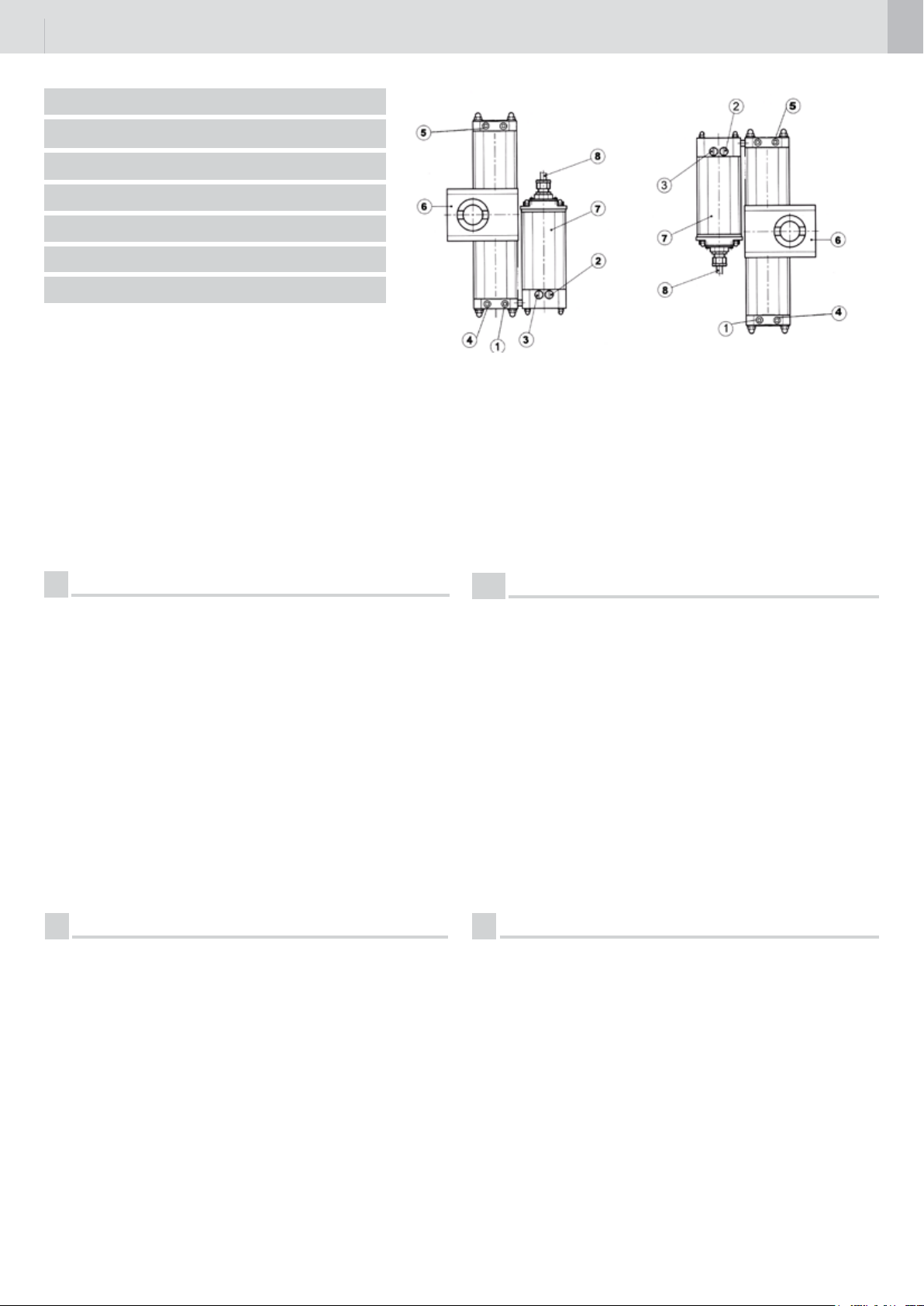
I
1 Dispositivo di sblocco per la manovra manuale.
2 Valvola di regolazione della forza in chiusura .
3 Valvola per la regolazione della forza in apertura .
4 Valvola di regolazione della velocità di rotazione in apertura.
5 Valvola di regolazione della velocità di rotazione in chiusura.
6 Martinetto.
7 Centralina idraulica.
8 Cavo di alimentazione.
FLOOR 810
REGOLAZIONE DELLA FORZA
Per aumentare la forza, con l’ausilio di un cacciavite, ruotare in senso orario la valvola
(2) chiusura e la valvola (3) apertura; per diminuire la forza ruotare le valvole in senso
antiorario.
ATTENZIONE
Nell’eseguire l’operazione di regolazione della forza, ruotare le valvole per gradi dolcemente senza svitarle o avvitarle completamente, tenendo presente che gli operatori vengono
forniti con la forza già regolata in modo ottimale in fase di collaudo.
L’operatore ha in dotazione le etichette regolazioni pressione per la versione destra e
sinistra da applicare sulla centralina.
N.B Con ante chiuse (cieche o superiori a 2,5m )in zone con vento di forte intensità si
consiglia l’uso dell’elettroserratura.
GRUPPO SINISTRO
VISTA INTERNA
PARTIE GAUCHE VUE
DE L’INTERIEUR
LEFT UNIT INTERNAL
VIEW
GRUPO IZQUIERDO
VISTA INTERIOR
GRUPO ESQUERDO
VISTA INTERIOR
BAUGRUPPE LINKS
INNENANSICHT
LINKSE EENHEID VAN
BINNENUIT GEZIEN
GRUPPO DESTRO
VISTA INTERNA
PARTIE DROITE VUE
DE L’INTERIEUR
RIGHT UNIT INTERNAL VIEW
GRUPO DERECHO
VISTA INTERIOR
GRUPO DIREITO VISTA
INTERIOR
BAUGRUPPE RECHTS
INNENANSICHT
RECHTSE EENHEID VAN
BINNENUIT GEZIEN
UK
1 Unlocking device for manual operation.
2 Valve for closing force adjustment .
3 Valve for opening force adjustment .
4 Valve for opening speed regulating.
5 Valve for closing speed regulating.
6 Jack.
7 Hydraulic control unit.
8 Power supply cable.
FLOOR 810
FORCE ADJUSTMENT
To increases the force, use a screw driver and turn the closing valve (2) and
the opening valve (3) in a clockwise direction; to decreases the force turn the valves
anticlockwise.
WARNING
When carrying out the force adjustment, turn the valves gently in small steps
without screwing or unscrewing them completely, bearing in mind that the operators are
supplied with the force already adjusted to the optimal setting during the test phase.The
pressure control labels for the right and left version are provided with the operator and
are to be applied on the control unit.
N.B. With closed gates (blind or higher to 2,5m) in areas where the wind is very strong,
it is recommended to use the electric lock.
F
1 Dispositif de déverrouillage pour la manoeuvre manuelle.
2 Soupape pour réglage de la force en fermeture .
3 Soupape pour réglage de la force en ouverture .
4 Soupape de réglage de la vitesse de rotation en ouverture.
5 Soupape de réglage de la vitesse de rotation en fermeture.
6 Vérin.
7 Distributeur oléodynamique.
8 Câble d’alimentation.
FLOOR 810
REGLAGE DE LA FORCE
Pour augmenter la force, utiliser un tournevis pour tourner la soupape (2) de fermeture
et la soupape (3) d’ouverture dans le sens des aiguilles d’une montre. Pour la diminuer,
tourner les soupapes dans le sens inverse des aiguilles d’une montre.
ATTENTION
Pendant le réglage de la force, tourner graduellement les soupapes sans les visser ou
dévisser complétement. Ne pas oublier que, lors de la livraison, la force des opérateurs
a déjà été convenablement réglée en phase d’essai.
L’opérateur est muni des étiquettes de réglage de la pression pour les versions droite et
gauche, à appliquer sur la platine.
N.B.: Il est conseillé d’utiliser l’électroserrure avec les vantaux fermés (tôle plaine ou
superieur a 2,5m)dans des zones où les vents sont particulièrement forts.
E
1 Dispositivo de desbloqueo para la maniobra manual.
2 Válvula para la regulación de la fuerza en cierre .
3 Válvula para la regulación de la fuerza en abertura .
4 Válvula de regulación de la velocidad de rotación en abertura.
5 Válvula de regulación de la velocidad de rotación en cierre.
6 Cilndro.
7 Unidad de fuerza hidráulica.
8 Cable de alimentación.
FLOOR 810
REGULACION DE LA FUERZA
Para aumentar la fuerza, con un destornillador girar en sentido horario la válvula (2) de
cierre y la válvula (3) de abertura. Para disminuir la fuerza, girar las Válvulas en sentido
antihorario.
ATENCION
Al efctuar la operación de regulación de la fuerza, girar las válvulas por grados suave-
mente sin aojarlas o ajustarlas completamente, teniendo en cuenta que los operadores
son suministrados con la fuerza ya regulada óptimamente durante la fase prueba nal.
El operador posee en dotación las etiquetas de regulación de la presión para la versión
derecha e izquierda que se tienen que aplicar en la centralita.
Nota: con las hojas cerradas (sin vista o superior a 2,5m)en zonas con viento muy intenso
se aconseja el uso de una electrocerradura.»

11
P
1 Dispositivo de desbloqueio para manobra manual.
2 Válvula de regulação da força de encerramento .
3 Válvula de regulação da força de abertura .
4 Válvulas de regulação da velocidade de rotação de abertura.
5 Válvulas de regulação da velocidade de rotação de encerramento.
6 Cilindro.
7 Central hidráulica.
8 Cabo de alimentação.
FLOOR 810
REGULAÇÃO DA FORÇA
Para aumentar a força, usar uma chave de parafusos e rodar no sentido horário a válvula
(2) de encerramento e a válvula (3) de abertura; para diminuir a força rodar as válvulas
no sentido anti-horário.
ATENÇÃO
Ao efectuar a regulação da força, rodar suavemente as válvulas, por graus, sem as
atarraxar ou desatarraxar completamente, considerando que os operadores já são
fornecidos com a força regulada em modo optimal durante a fase de prova.O operador
é fornecido de série com as etiquetas para regulações de pressão, para a versão direita
e esquerda, que se têm de aplicar na unidade de comando.
Nota: com portas fechadas (tapado o superior a 2,5m) em zonas com vento de forte
intensidade aconselhamos a usar um trinco eléctrico
NL
1 Ontgrendelingsventiel voor manuele bediening
2 Ventiel voor afregeling van de sluitingskracht
3 Ventiel voor afregeling van de openingskracht
4 Snelheidsregelaars
5 Snelheidsregelaars
6 Cilindereenheid
7 Hydraulische eenheid
8 Voedingskabel
FLOOR 810
KRACHTAFREGELINGEN
Om de krachten te verhogen : gebruik een schroevendraaier en draai het ventiel voor
sluitingskracht (2) en het ventiel voor openingskracht (3) in uurwijzerzin.
Om de krachten te verlagen : draai de ventielen tegenuurwijzerzin
WAARSCHUWING
Draai de regelventielen nooit volledig los of vast maar verdraai ze stapsgewijs. Vergeet
niet dat de kracht van de openers reeds optimaal ingesteld is tijdens de proeffase.
De motors zijn voorzien van een label met vermelding van de krachten voor de linker en
rechter versie, die dienen toegepast te worden op de stuurkast.
N.B. Voor gesloten poorten of poorten hoger dan 2,5 m. is het aan te raden een elektrisch
slot te plaatsen voor de windbelasting.
D
1 Entriegelungsvorrichtung für die manuelle Bewegung.
2 Ventil zur Einstellung der Schubkraft beim Schließen.
3 Ventil zur Einstellung der Schubkraft beim Öffnen.
4 Ventil zur Einstellung der Drehgeschwindigkeit beim Öffnen.
5 Ventil zur Einstellung der Drehgeschwindigkeit beim Schließen.
6 Hydraulikzentrale
7 Stromkabel
FLOOR 810
SCHUBKRAFTEINSTELLUNG
Zum Erhöhen der Schubkraft anhand eines Schraubenziehers das Schließungsventil (2)
und das Öffnungsventil (3) im Uhrzeigersinn drehen.
Zur Verringerung der Schubkraft, die Ventile gegen Uhrzeigersinn drehen.
ACHTUNG
Bei der Schubkrafteinstellung die Ventile behutsam stufenweise drehen und nicht ganz
zu- oder aufschrauben. Die Antriebe werden mit bereits gelegentlich der Abnahme optimal
eingestellter Schubkraft geliefert.
Mit dem Antrieb werden Etiketten für die Anzeige der Druckregelung für die rechts und
links montierte Version zum Anbringen an der Hydraulikzentrale geliefert.
Anmerkung: Bei Torügeln ohne Öffnungen (mit vollem Torblatt oder bei Höhe über 2,5 m)
wird in Gebieten mit starkem Wind der Einsatz des Elektroschlosses empfohlen.
REGOLAZIONE DELLA FORZA FLOOR 812
REGLAGE DE LA FORCE FLOOR 812
FORCE ADJUSTMENT FLOOR 812
REGULACIÓN DE LA FUERZA FLOOR 812
REGULAÇÃO DA FORÇA FLOOR 812
SCHUBKRAFTEINSTELLUNG FLOOR 812
KRACHTREGELING FLOOR 812
I
Per la regolazione della forza degli operatori utilizzare ESCLUSIVAMENTE
l’apposito trimmer posizionato sull’apparecchiatura elettronica.
N.B: non modicare le impostazione delle valvole di regolazione pressione poste
sulla centralina idraulica.
F
Pour le reglage de la force utiliser le trimmer positionè sur la platine. L’etallonage
des soupapes de reglage de la pression situées sur le distributeur olèodinamique
ne peut pas être modiè.
UK
For force adjustement use the trimmer installed on the electronic board.
Do not modify setting of pressure control valves on the hydraulic control unit.
E
Para la regulación de fuerza de los operadores utilizar solamente el trimmer
apropiado que se encuentra nel equipo electronico. N.B. no modicar la regulación de
las valvulas de regulación presión puestas en la central hidraulica.
P
Para a regulação da forçam o perador deve utilizar exclusivamente o triòer
posicionado acima do aparelho electronico. N.B. Não modicar a pocição da pressão
colocada na centralina hidraulica.
NL
Voor de regeling van de kracht, gebruik UITSLUITEND de potentiometer welke zich
bevindt op de elektronische besturingskast.
N.B. Wijzig nooit de instelling van de hydraulische regelventielen op de
verdeelblok van de hydraulische unit.
D
Für die Schubkrafteinstellung der Antriebe AUSSCHLIESSLICH den hierfür
vorgesehenen Trimmer verwenden, der sich am Steuergerät bendet.
ANMERKUNG: Die Einstellung der Druckeinstellungsventile an der Hydraulikzentrale
nicht ändern.

12
REGOLAZIONE VELOCITA’
REGLAGE DE LA VITESSE
SPEED CONTROL
REGULACIÓN DE LA VELOCIDAD
REGULAÇÃO DE LA VELOCIDAD
GESCHWINDIGKEITSEINSTELLUNG
REGELING VAN DE SNELHEID
I
Utilizzando la chiave per la manovra manuale (vedi pag.12) ruotare in senso
orario per diminuire la velocità di rotazione, la valvola N°5 per la chiusura e la
N°4 per l’apertura.
F
Utilizer la clé pour la manoeuvre manuelle (voir page 12) et tourner dans le sens
des aiguilles d’une montre pour la vitesse de rotation, la soupape nr 5 pour la
fermeture , et la soupape nr 4 pour overture.
UK
Use special key (see page 12) and turn clockwise valve nr 5 for closing and nr 4 for
opening in order to reduce rotation speed.
E
Utilizando la llave da maniobra manual (ver pag.12) girar en sentido horario para disminuir la velocidad de rotation, la valvula n°5 para el cierre y la n°4 para la aberdura.
P
Utilizando a chave para a manobra manual (ver pag.12) rodar no sentido dos ponteiros
do relogio para diminuir a velocidade de rotação, a valvula n° 5 para fechar, e a valvula
n° 4 para abrir.
D
Mit Hilfe des Schlüssels für die manuelle Bewegung (siehe S. 12) das
Schließungsventil Nr. 5 und das Öffnungsventil Nr. 4 im Uhrzeigersinn drehen, um die
Drehgeschwindigkeit zu senken.
NL
Gebruik de ontgrendelingssleutel (zie blz. 12) en draai het ventiel nr. 5 uurwijzerzin. Voor
de reductie van de snelheid in de sluitrichting en het
ventiel nr. 4 voor de openrichting.
MANOVRA MANUALE
MANOUVRE MANUELLE
MANUAL OPERATION
MANIOBRA MANUAL
MANOBRA MANUAL
MANUELLE BEWEGUNG
MANUELE ONTGRENDELING
I
DISPOSITIVO PER LA MANOVRA MANUALE
1 Tappo
2 Chiave
3 Foro di accesso al dispositivo di sblocco per la manovra manuale.
MANOVRA MANUALE
Svitare il tappo (1) .
Inserire la chiave (2) nel foro (3), ruotare la chiave in senso antiorario di
almeno un giro senza forzarla, quindi eseguire dolcemente la manovra
manuale del cancello.
Per il ripristino in automatico ruotare la chiave (2) in senso orario no
quando non arriva bene in battuta.
ATTENZIONE: Effettuare le operazioni per la manovra manuale
con motore fermo.
F
DISPOSITIF POUR LA MANOEUVRE MANUELLE
1 Bouchon
2 Clé
3 Trou d’acceès au dispositif de déverrouillage pour la manoeuvre
manuelle.
MANOEUVRE MANUELLE
Dèvisser le bouchon (1) .
Enfoncer la clé (2) dans le trou (3), la tourner d’au moins un tiur dans
le sens inverse des aiguilles d’une montre sans la forcer et procéder
graduellement à la manoeuvre manuelle de la grille.
Pour revenir au fonctionnement automatique, tourner la clé (2) dans le
sens des aiguilles d’une montre jusqu’à atteindre sa butée.
ATTENTION: Effectuer les opérations de manoeuvre manuelle
après avoir arrêté le moteur.

13
E
DISPOSITIVO PARA LA MANIOBRA MANUAL
1 Tapón
2 Llave
3 Agujero de acceso al dispositivo de desbloqueo para la
maniobra manual.
MANIOBRA MANUAL
Desenroscar el tapón (1) .
Introducir la llave (2) en el agujero (3), girarla al menos una vuelta en
sentido antihorario sin forzarla; luego, efectuar suavement la maniobra
manual de la puerta.
Para el restablecimiento automático, girar la llave (2) en sentido horario
hasta que llegue bien al tope.
Atención: cumplir las operaciones para la maniobra manual con
motor parado.
P
DISPOSITIVO PARA A MANOBRA MANUAL
1 Tampa
2 Chave
3 Furo de acesso ao dispositivo de desbloqueio para manobra manual
MANOBRA MANUAL
Desaperte a tampa (1) .
Introduzir a chave (2) no orifício (3), rodar a chave no sentido anti-horário
de pelo menos uma volta sem a esforçar; depois efectuar suavemente a
manobra manual do portão.
Para restabelecer o funcionamento automático rodar completamente a
chave (2) no sentido horário.
ATENÇÃO: Efectuar as operações de manobra manual somente com
o motor parado.
UK
DEVICE FOR MANUAL OPERATION
1 Cap
2 Key
3 Access hole to unlocking device for manual operation
MANUAL OPERATION
Unscrew the cap (1) .
Insert the key (2) in the hole (3), turn the key in an anti-clockwise direction by at least one turn without forcing it. Then gently carry out the
manual operation of the gate.
To reset to automatic operation, turn the key (2) in a clockwise direction
until it rmly reaches the rabbet.
WARNING: Carry out the manual operations with the motor off.
D
VORRICHTUNG FÜR DIE MANUELLE BEWEGUNG
1 Deckel
2 Schlüssel
3 Zugangsöffnung zur Entriegelungsvorrichtung für die manuelle Bewegung.
MANUELLE BEWEGUNG
Den Deckel (1) abschrauben.
Den Schlüssel (2) in die Öffnung (3) einstecken, den Schlüssel behutsam
mindestens eine Umdrehung gegen den Uhrzeigersinn drehen und dann
die manuelle Bewegung des Tors vorsichtig ausführen.
Zum Zurückschalten auf Automatikbetrieb den Schlüssel (2) im Uhrzeigersinn bis zum Anschlag drehen.
ACHTUNG: Die manuelle Bewegung bei stillstehendem Motor
durchführen.
um
NL
VENTIEL VOOR DE MANUELE ONTGRENDELING
1. Afschermdop
2. Ontgrendelingssleutel
3. Toegangsopening voor manuele ontgrendeling
MANUELE ONTGRENDELING
Verwijder de afschermdop (1)
Steek de sleutel (2) in de opening (3), en draai minimum één omwenteling tegenuurwijzerzin zonder gebruik te maken van grote krachten.
Dan kan de poort voorzichtig manueel bediend worden
Om de poort terug automatisch te bedienen, draai de sleutel (2) in de
uurwijzerzin tot het einde van zijn aanslag.
OPGELET: De manuele ontgrendeling kan slechts gebeuren wanneer de opener niet in werking is.

14
ELETTROSERRATURA
ELECTROSERRURE
ELECTROLOCK
ELECTROCERRADURA
FECHADURA ELÉCTRICA
ELEKTROSCHLOSS
ELEKTRISCH SLOT
I
MONTAGGIO ELETTROSERRATURA
1 Elettroserratura
2 Piastra di ssaggio elettroserratura
3 Aggancio chiavistello
4 Battuta per aggancio chiavistello
5 Chiavistello
6 Barilotto passante (a richiesta)
7 Cancello
F
MONTAGE DE L’ELECTROSERRURE
1 Electroserrure
2 Tôle de xation de l’électroserrure
3 Gâche du pêne
4 Epaulement pour la gâche du pêne
5 Pêne
6 Cylindre à double sortie (sur demande)
7 Grille
UK
MOUNTING THE ELECTROLOCK
1 Electrolock
2 electrolock xing plate
3 Bolt hooker
4 Bolt hooking rabbet
5 Bolt
6 Key cylinder (on request)
7 Gate
E
MONTAJE DE LA ELECTROCERRADURA
1 Electrocerradura
2 Placa de jación de la electrocerradura
3 Cerradero del pestillo
4 Tope para el cerradero del pestillo
5 Pestillo
6 Cilindro doble (sobre pedido)
7 Reja

15
P
MONTAGEM DA FECHADURA ELÉCTRICA
1 Fechadura eléctrica
2 Chapa de xação da fechadura eléctrica
3 Enganchamento do ferrolho
4 Batente para enganchamento do ferrolho
5 Ferrolho
6 Cilindro duplo (a pedido)
7 Portão
NL
MONTAGE VAN HET ELEKTRISCH SLOT
1 Elektrisch slot
2 Bevestigingsplaat van het elektrisch slot
3 Penvanger
4 Bevestigingsplaat van de penvanger
5 Pen
6 Cilinderslot (op aanvraag)
7 Poort
D
ELEKTROSCHLOSSMONTAGE
1 Elektroschloss
2 Befestigungsplatte Elektroschloss
3 Riegelkopplung
4 Anschlag für Riegelkopplung
5 Riegel
6 Durchgehender Zylinder (auf Anfrage)
7 Tor
CARATTERISTICHE TECNICHE
CARACTERISTIQUES TECHNIQUES
TECHNICAL CHARACTERISTICS
CARACTERÍSTICAS TÉCNICAS
TECNISCHE DATEN
TECNISCHE SPECIFICATIES
CARACTERÍSTICAS TÉCNICAS
ALIMENTAZIONE / ALIMENTATION / POWER SUPPLY / ALIMENTACION /
ALIMENTAÇÃO / STROMVERSORGUNG / VOEDINGSSPANNING-FREQUENTIE
POTENZA ASSORBITA / PUISSANCE ABSORBEE / ABDORBED POWER
POTENCIA ABSORBIDA / POTÊNCIA ABSORVIDA / LEISTUNGSAUFNAHME /
OPGENOMEN VERMOGEN
CORRENTE ASSORBITA / COURANT ABSORBE / ABSORBED CURRENT /
CORRIENTE ABSORBIDA / CORRENTE ABSORVIDA / STROMAUFNAHME /
OPGENOMEN STROOM
ANGOLO DI ROTAZIONE / ANGLE DE ROTATION / ROTATION ANGLE /
ANGULO DE ROTACIÓN / ANGULO DE ROTAÇÃO /DREHWINKEL /
MAXIMUM DRAAIHOEK
FLOOR 812
12 V DC
MAX 60W
MAX 5 A
170°
FLOOR 810
220-230 V
50-60 Hz
MAX 190 W
MAX 0,83 A
170°
VELOCITA’ ANGOLARE MAX / VITESSE ANGULAIRE MAXI /MAX. ANGULAR/
SPEED / VELOCIDAD ANGULAR MÁXIMA / VELOCIDADE ANGULAR MÁX. / MAX.
WINKELGESCHWINDIGKEIT / MAXIMUM DRAAISNELHEID
7°/s
7°/s

16
TEMPO DI APERTURA A 90° / TEMPS D’OUVERTURE A 90° / TIME TO OPEN
UP TO 90° TIEMPO DE ABERTURA A 90° / TEMPO DE ABERTURA A 90° / ÖFF
NUNGSZEIT 90°
COPPIA MAX / COUPLE MAXI/MAX. TORQUE / PAR MÁXIMO /
TORQUE MÁX./ MAX. DREH MOMENT
CONDENSATORE / CONDENSATEUR / CAPACITOR / CONDENSADOR
CONDENSADOR / KONDENSATOR
PRESSIONE DI ESERCIZIO MAX / PRESSION D’EMPLOI MAXI / MAX.
OPERATING PRESSURE / PRESIÓN DE EJERCICIO MÁXIMA / PRESSÃO
DE EXERCÍCIO MÁX. / MAX. BETRIEBSDRUCK
TEMPERATURA DI ESERCIZIO / TEMPERATURE D’EMPLOI
WORKING TEMPERATURE / TEMPERATURA DE EJERCICIO
TEMPERATURA DE EXERCÍCIO / BETRIEBSTEMPERATUR /
WERKINGSTEMPERATUR
OLIO IDRAULICO /
HIDRÁULICO / ÓLEO HIDRÁULICO / HYDRAULIKÖl / HYDRAULISCHE OLIE
HUILE HYDRAULIQUE / HYDRAULIC OIL / ACEITE
FLOOR 812
13 s
200 Nm
-
4000 KPa
(40 bar)
-20°C +60°C
TOTAL EQUIVIS
HVG 22 I
FLOOR 810
13 s
220 Nm
10 µF
4000 KPa
(40 bar)
-20°C +60°C
TOTAL EQUIVIS
HVG 22 I
CICLI PER ORA (COMPLETI) / CYCLES - HEURE (COMPLETS) / CYCLES PER
HOUR (FULL OPEN & CLOSE) / CICLOS PO HORA (COMPLETOS) /
CICLOS POR HORA (COMPLETOS) / ZYKLEN (KOMPLETT) PRO STUNDE /
AANTALBEWEGINGEN PER UUR (VOLLEDIG OPEN EN DITCH)
CICLI AL GIORNO / CYCLES - JOUR / CYCLES PER DAY
CICLOS POR DIA / CICLOS POR DIA / ZYKLEN PRO TAG /
AANTAL BEWEGINGEN PER DAG
BLOCCO IDRAULICO GARANTITO PER ANTE DI LUNGHEZZA MASSIMA /
BLOCAGE HYDRAULIQUE ASSURE POUR DES VANTAUX DE LONFEUR MAXI. /
GUARANTEED HYDRAULIC LOCK FOR SWINGS OF A MAX. LENGTH OF /
BLOQUEO HIDRAULICO GARANTIZADO PARA HOJAS DE LONGITUD MAXIMA
BLOCAGEM HIDRÁULICA GARANTIDA PARA FOLHAS COMPRIMENTO MÁX./
GARANTIERTE HYDRAULISCHE BLOCKIERUNG FÜR FLÜGEL MIT HÖCHSTÄNGE/
HYDRAULISCHE VERGRENDELING GEGARANDEERD TOT EEN MAXIMUM
VLEUGELBREEDTE VAN
GRADO DI PROTEZIONE IP / IP NUMBER / GRADO DE PROTECCIÓN IP / GRADO DE PROTECÇAO IT/ DEGRÉ DE PROTECTION IP /
IP BESCHERMINGSFACTOR / IP SCHUTZKLASSE
20
200
1,5 m
IP 67 IP 67
20
200
1,5 m

17
Dichiarazione di conformità CE
Il fabbricante:
GI.BI.DI. S.r.l.
Via Abetone Brennero, 177/B,
46025 Poggio Rusco (MN) ITALY
Dichiara che i prodotti:
operatore oleodinamico: FLOOR 810 - FLOOR 812
Sono conformi alle seguenti Direttive CEE:
• Direttiva LVD 2006/95/CE e successive modiche
(FLOOR 810);
• Direttiva EMC 2004/108/CE e successive modiche;
e che sono state applicate le seguenti norme armonizzate:
• EN61000-6-1, EN61000-6-3, EN60335-1
Data 05/06/08
CE Declaration of conformity
The manufacturer:
GI.BI.DI. S.r.l.
Via Abetone Brennero, 177/B,
46025 Poggio Rusco (MN) ITALY
Declares that the products:
hydraulic operator: FLOOR 810 - FLOOR 812
Are in conformity with the following CEE Directives:
• LVD Directive 2006/95/CE and subsequent amendments
(FLOOR 810);
• EMC Directive 2004/108/CE and subsequent amendments;
and that the following harmonised standards have been applied:
• EN61000-6-1, EN61000-6-3, EN60335-1
Date 05/06/08
Firma Ammistratore Delegato
Oliviero Arosio
Déclaration de conformité CE
La société:
GI.BI.DI. S.r.l.
Via Abetone Brennero, 177/B,
46025 Poggio Rusco (MN) ITALY
Déclare que les produits:
opérateurs hydrauliques: FLOOR 810 - FLOOR 812
Sont en conformité avec les exigences des Directives CEE:
• Directive LVD 2006/95/CE et ses modications
(FLOOR 810);
• Directive EMC 2004/108/CE et ses modications;
Managing Director
Oliviero Arosio
Declaración de conformidad CE
El fabricante:
GI.BI.DI. S.r.l.
Via Abetone Brennero, 177/B,
46025 Poggio Rusco (MN) ITALY
Declara que los productos:
operadores oleodinámicos: FLOOR 810 - FLOOR 812
Cumplen la siguiente Directiva CEE:
• Directiva LVD 2006/95/CE y modicaciones sucesivas
(FLOOR 810);
• Directiva EMC 2004/108/CE y modicaciones sucesivas;
et que les normes harmonisées suivantes ont été appliquées :
• EN61000-6-1, EN61000-6-3, EN60335-1
Date 05/06/08
Signature Administrateur Délégué
Oliviero Arosio
y que se han aplicado las siguientes normas armonizadas:
• EN61000-6-1, EN61000-6-3, EN60335-1
Fecha 05/06/08
Firma Administrador Delegado
Oliviero Arosio

18
CE-Konformitätserklärung
Der Hersteller:
GI.BI.DI. S.r.l.
Via Abetone Brennero, 177/B,
46025 Poggio Rusco (MN) ITALY
Erklärt, dass die Produkte:
ölhydraulische antrieb: FLOOR 810 - FLOOR 812
Den folgenden CEE-Richtlinien entsprechen:
• LVD-Richtlinie 2006/95/CE und nachfolgende Änderungen
(FLOOR 810);
• EMV-Richtlinie 2004/108/CE und nachfolgende
Änderungen;
und dass die nachfolgenden harmonisierten Vorschriften
angewendet wurden:
• EN61000-6-1, EN61000-6-3, EN60335-1
Data 05/06/08
Unterschrift des Geschäftsführers
Oliviero Arosio
Declaração de conformidade CE
O fabricante:
GI.BI.DI. S.r.l.
Via Abetone Brennero, 177/B,
46025 Poggio Rusco (MN) ITALY
Declara que os produtos:
operador óleo-dinâmicos: FLOOR 810 - FLOOR 812
Estão em conformidade com as seguintes Directivas CEE:
• Directiva LVD 2006/95/CE e alterações posteriores
(FLOOR 810);
• Directiva EMC 2004/108/CE e alterações posteriores;
e que foram aplicadas as seguintes normas harmonizadas:
• EN61000-6-1, EN61000-6-3, EN60335-1
Data 05/06/08
Assinatura do Administrador Delegado
Oliviero Arosio
CE-Conformiteitsverklaring
De fabrikant:
GI.BI.DI. S.r.l.
Via Abetone Brennero, 177/B,
46025 Poggio Rusco (MN) ITALY
Verklaart dat de producten:
oleodynamische operatoren: FLOOR 810 - FLOOR 812
Conform de volgende CEE-richtlijnen zijn:
• Richtlijn LVD 2006/95/CE en daaropvolgende wijzigingen;
(FLOOR 810);
• Richtlijn EMC 2004/108/CE en daaropvolgende wijzigingen;
en dat de volgende geharmoniseerde normen werden toegepast:
• EN61000-6-1, EN61000-6-3, EN60335-1
Datum 05/06/08
Handtekening Zaakvoerder
Oliviero Arosio

19
NOTE

AIC3131 - 06/08 - REV06
GI.BI.DI. S.r.l.
Via Abetone Brennero, 177/B
46025 Poggio Rusco (MN) - ITALY
Tel. +39.0386.52.20.11
Fax +39.0386.52.20.31
E-mail: comm@gibidi.com
Numero Verde: 800.290156
www.gibidi.com
 Loading...