

ART
ART (5000 - 5012 - 5024)
Operatore elettromeccanico
ISTRUZIONI PER L’INSTALLAZIONE
Electromechanical operator
INSTRUCTIONS FOR INSTALLATION
I IF UK D
E DP NL
2
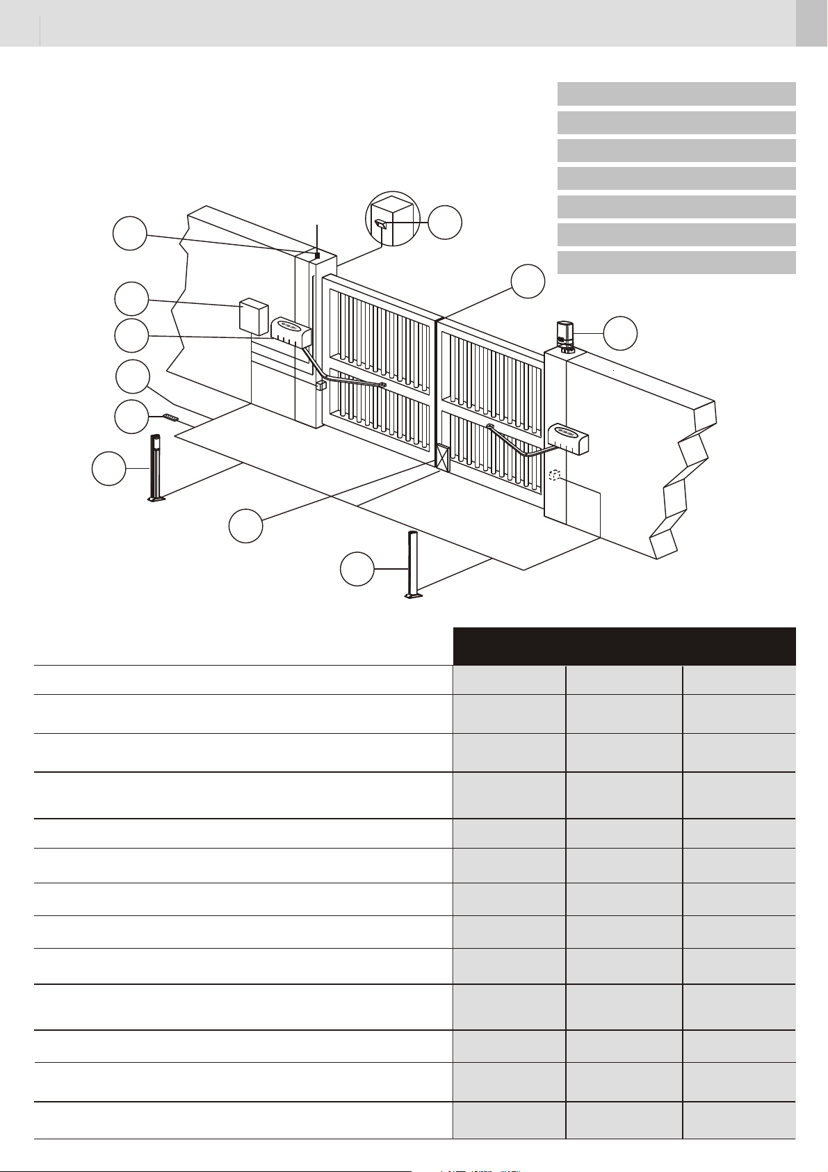
PREDISPOSIZIONI ELETTRICHE
APPAREILLAGES ELECTRIQUES
ELECTRICAL CONNECTIONS
EQUIPOS ELECTRICOS
EQUIPAMENTO ELÉCTRICO
8
5
ELEKTROAUSSTATTUNG
ELEKTRISCHE AANSLUITINGEN
1
2
3
6
4
10
11
9
ALIMENTAZIONE / ALIMENTATION/POWER SUPPLY / ALIMENTACION /ALIMENTAÇÃO /
SROMVERSORGUNG / VOEDINGS SPANNING
POTENZA ASSORBITA / PUISSANCE ABSORBEE / ABDORBED POWER / POTENCIA ABSORBIDA /
POTÊNCIA ABSORVIDA / LEISTUNGSAUFNAHME / OPGENOMEN VERMOGEN
CORRENTE ASSORBITA / COURANT ABSORBEE / ABDORBED CURRENT / CORRIENTE ABSORBIDA /
CORRENTE ABSORVIDA / STROMAUFNAHME / OPGENOMEN STROOM
ART5000
220/230 V-50Hz
200 W
1 A
7
ART5012 ART5024
12 Vdc
70 W
6 A
24 Vdc
100 W
5 A
TERMICA PROTEZIONE MOTORE / PROTETION THERMIQUE DU MOTEUR / MOTOR OVERLOAD /
PROTECCION TERMICA DEL MOTOR / PROTECÇÃO TÉRMICA DO MOTOR / ÜBERSTROMSCHALTER /
THERMISCE BEVEILING VAN DE OPENER
CONDENSATORE / CONDENSATEUR / CAPACITOR / CONDENSADOR / CONDENSADOR / KONDENSATOR /
CONDENSATOR
VELOCITA’ ANGOLARE MAX / VITESSE ANGULAIRE MAXI / MAX. ANGULAR SPEED VELOCIDAD ANGULAR
MÁXIMA / VELOCIDADE ANGULAR MÂX. / MAX LINEARE GESCHWINDIGKEIT / MAX LINEARE SNELHEID
TEMPO DI APERTURA A 90° / TEMPS D’OUVERTURE A 90° / TIME TO OPEN UP TO 90° / TIEMPO DE
ABERTURA A 90°/ TEMPO DE ABERTURA A 90° / ÖFF NUNGSZEIT 90° / OPENINGSTIJD VOOR 90°
COPPIA MAX / COUPLE MAXI / MAX. TORQUE / PAR MÁXIMO / TORQUE MÁX. / MAX DREHMOMENT /
MAX KOPPEL
TEMPERATURA DI ESERCIZIO / TEMPERATURE D’EMPLOI / WORKING TEMPERATURE / TEMPERATURA
DE EJERCICIO / TEMPERATURA DE EXERCÍCIO / BETRIEBSTEMPERATUR / WERKINGSTEMPERATUUR
CICLI PER ORA (COMPLETI) / CYCLES - HEURE (COMPLETS) / CYCLES PER HOUR
(FULL OPEN & CLOSE) / CICLOS PO HORA (COMPLETOS) / CICLOS POR HORA (COMPLETOS) /
ZYKLEN (KOMPLETT) PRO STUNDE / AANTAL BEWEGINGEN PER UUR (VOLLEDIG OPEN EN DITCH)
CICLI AL GIORNO / CYCLES - JOUR / CYCLES PER DAY / CICLOS POR DIA / CICLOS POR DIA /
ZYKLEN PRO TAG / AANTAL CYLCI PER DAG.
LUNGHEZZA MAX. ANTA / LONGEUR MAXI DU BATTANT / MAX LEAF LENGHT / LONGITUD HOJA MAX. /
COMPRIMENTO MÁX. DA FOLHA / MAX LÄNGETORFLÜGEL / MAX VLEUGELBREEDTE
PROTEZIONE CONTRO L’UMIDITÁ / PROTECTION CONTRE L’HUMIDITÉ/ PROTECTION AGAINST WETNESS
PROTECCION CONTRA LA HUMEDAD/ PROTECÇÃO/CONTRA A HUMIDADE / FEUCHTIGKEITSSCHUTZ /
BESCHERMING TEGEN VOCHTIGHEID
10 µF
7,8 °/sec
17 s
250 Nm
-20°C +60°C
20 Max
200
3 m
-
-
7,6 °/sec
18 s
220 Nm
-20°C +60°C -20°C +60°C
40 Max
200
3 m
IP53 IP53IP53
-140°
-
5,6 °/sec
24 s
220 Nm
40 Max
200
3 m

3
I
1 Coste sensibili.
2 Contenitore apparecchiatura elettronica.
3 Operatori. ART5000: cavo a 7 conduttori da 1,5 mm².
ART5012, ART5024: cavo a 5 conduttori da 1,5 mm² per distanze max.3m
dall’apparecchiatura; per distanze maggiori cavo da 2.5mm² (max.6m).In
entrambi i casi 3 conduttori sono utilizzati per il collegamento dei finecorsa.
4 Pulsantiera; cavo a 5 conduttori da 0,5 mm².
5 Selettore a chiave; cavo a 3 conduttori da 0,5 mm².
6 Linea di alimentazione all’apparecchiatura 220-230 V 50-60 Hz; cavo a 3
conduttori da 1,5 mm² min. (attenersi alle Norme vigenti).
7 Segnalatore a luce lampeggiante; cavo a 2 conduttori da 1,5 mm².
8 Antenna.
9 Trasmettitore fotocellula; cavo a 2 conduttori da 0,5 mm²
10 Ricevitore fotocellula; cavo a 4 conduttori da 0,5 mm²
11 Elettroserratura.
ATTENZIONE: è importante che sulla linea di alimentazione venga installato, a
monte dell’apparecchiatura, un interruttore magnetotermico onnipolare con
aper tura minima dei contatti pari a 3 mm.
F
1 Barres palpeuses.
2 Boîtier de la platine électronique.
3 Opérateurs. ART5000: câble à 7 conducteurs de 1,5 mm².
ART5012, ART5024: câble à 5 conducteurs de 1,5 mm²pour distances max.3m
de la platine de commande; pour distances supérieures câble de 2.5mm²
(max.6m). Dans les deux cas 3 conducteurs sont utilisés pour la connexion des
fins de course.
4 Tableau de commande; câble à 5 conducteurs de 0,5 mm².
5 Sélecteur à clé; câble à 3 conducteurs de 0,5 mm².
6 Ligne d’alimentation de la platine 220-230 V 50-60 Hz; câble à 3 conducteurs de
1,5mm2 mini (respecter les normes en vigueur).
7 Clignotant; câble à 2 conducteurs de 1,5 mm².
8 Antenne.
9 Emetteur cellule photo-électrique; câble à 2 conducteurs de 0,5 mm².
10 Récepteur cellule photo-électrique; câble à 4 conducteurs de 0,5 mm².
11 Electroserrure.
ATTENTION: Sur la ligne d’alimentation, en amont de la platine, il est important
de monter un interrupteur magnétothermique omnipolaire ayant une ouverture
des contacts minimale de 3 mm.
UK
1 Sensitive frame.
2 Electronic equipment container.
3 Operators. ART5000: cable with 7 conductors of 1.5 mm².
ART5012, ART5024: cable with 5 conductors of 1.5 mm²for distances max.3m
from the control unit; for bigger distances cable of 2.5mm² (max.6m). In both
cases 3 conductors are used for the limit switch connection.
4 Push-button panel; cable with 5 conductors of 0.5 mm².
5 Key-selector; cable with 3 conductors of 0.5 mm².
6 Power supply line to equipment 220-230V 50-60Hz, cable with 3 conductors of
min. 1.5 mm² (follow regulations in force).
7 Flashing light; cable with 2 conductors of 1,5 mm².
8 Antenna.
9 Photocell transmitter; cable with 2 conductors of 0.5 mm².
10 Photocell receiver; cable with 4 conductors of 0.5 mm².
11 Electric lock.
WARNING: It is important that an omnipolar magneto-thermal switch with a
contact opening of minimum 3 mm is installed on the power supply line,
upstream of the equipment.
E
1 Bandas sensibles.
2 Contenedor del equipo electrónico.
3 Operadores. ART5000: cable de 7 conductores de 1,5 mm².
ART5012, ART5024: cable de 5 conductores de 1,5 mm² para distancias max.
3m del equipo de mando; para distancias superiores cable de 2.5mm²
(max.6m). En ambos casos 3 conductores son utilizados para la conexión de los
finales de carrera.
4 Botonera; cable de 5 conductores de 0,5 mm².
5 Selector de llave; cable de 3 conductores de 0,5 mm².
6 Línea de alimentación al equipo 220-230 V 50-60 Hz; cable de 3 conductores de
1,5 mm² (mínimo) (atenerse a las normas vigentes).
7 Destellador; cable de 2 conductores de 1,5 mm².
8 Antena.
9 Fotocélula transmisora; cable de 2 conductores de 0,5 mm².
10 Fotocélula receptora; cable de 4 conductores de 0,5 mm².
11 Electrocerradura.
ATENCIÓN: es importante instalar en la línea de alimentación, antes del equipo,
un interruptor magnetotérmico omnipolar con abertura mínima de los
contactos igual a 3 mm.
P
1 Banda sensível.
2 Caixa da aparelhagem electrónica.
3 Operador. ART5000: cabo com 7 condutores de 1,5 mm².
ART5012, ART5024: cabo com 5 condutores de 1,5 mm² para distância máx.de
3m do aparelho; para distâncias maiores, cabo de 2.5mm² (máx.6m). Em
ambos os casos são utilizados 3 condutores para a ligação dos interruptores de
fim de curso.
4 Painel de terminais; cabo com 4 condutores de 0,5 mm².
5 Selector de chave; cabo com 3 condutores de 0,5 mm².
6 Linha de alimentação da aparelhagem 220-230 V 50-60 Hz; cabo com 3
condutores de 1,5 mm² mín. (respeitar as normas vigentes).
7 Lâmpada pisca-pisca a 220 V ou 12 V; cabo com 2 condutores de 1,5mm².
8 Antena.
9 Transmissor fotocélula; cabo com 2 condutores de 0,5 mm².
10 Receptor fotocélula; cabo com 4 condutores de 0,5 mm².
11 Fechadura eléctrica; cabo com 2 condutores de 1,5 mm².
ATENCIÓN: é impor tante instalar sobre a linha de alimentação, antes da
aparelhagem, um interruptor magnetotérmico omnipolar com abertura mínima
dos contactos igual a 3 mm.
D
1 Kontaktschienen
2 Steuergerätgehäuse
3 Antrieb ART5000: 7-Leiter-Kabel 1,5 mm².
ART5012, ART5024: 5-Leiter-Kabel 1,5 mm² für Entfernungen bis max.3m vom
Gerät; für größere Entfernungen kabel mit 2.5mm² (bis max.6m). Bei beiden
Ausführungen werden 3 Leiter für den Anschluss der Endschalter verwendet.
4 Druckknopftafel: 5-Leiter-Kabel 0,5 mm²
5 Schlüsselschalter: 3-Leiter-Kabel 0,5 mm²
6 Versorgungsleitung zum Steuergerät 220-230V, 50-60 Hz: 3-Leiter- Kabel 1,5
mm² (die geltenden Vorschriften befolgen).
7 Blinklicht: 2-Leiter-Kabel 1,5 mm²
8 Antenne
9 Lichtschrankensender: 2-Leiter-Kabel 0,5 mm²
10 Lichtschrankenempfänger: 4-Leiter-Kabel 0,5 mm²
11 Elektroschloss
ACHTUNG: An der Versorgungsleitung vor dem Steuergerät unbedingt einen
allpoligen, thermomagnetischen Schalter mit einer Kontaktweite von
mindestens 3 mm anbringen.
NL
1 Veiligheidsstrip
2 Besturingskast
3 Openers ART5000 - 7 draden sectie 1,5 mm²
ART5012, ART5024 - 5 draden sectie 1,5 mm²
de apparatuur; voor langere afstanden, kabel van 2.50mm² (max.6meter). waarvan 3
draden worden gebruikt door de aansluiting van de einderitschakelaars
4 Drukknoppaneel : 5 draden sectie 0,5 mm²
5 Sleutelcontact : 3 draden sectie 0,5 mm²
6 Voedingsspanning 220-230 V, 50-60 Hz : 3 draden min. sectie 1,5 mm5
(respecteer de van kracht zijnde normen)
7 Knipperlicht 220 V : 2 draden sectie 1,5 mm²
8 Antenne
9 Infrarood fotocel zender : 2 draden sectie 0,5 mm²
10 Infrarood fotocel ontvanger : 4 draden sectie 0,5 mm².
11 Elektrisch slot
OPGELET : Het is heel belangrijk dat er een onderbrekingsschakelaar wordt
geplaatst op alle voedingsdraden. De minimum opening van deze
schakelcontacten moet 3 mm. bedragen.
voor een max. afstand van 3 meter van

4
AVVERTENZE PRELIMINARI
MISES EN GARDE PRELIMINAIRES
PRELIMINARY WARNINGS
ADVERTENCIAS PRELIMINARES
ADVERTÊNCIAS PRELIMINARES
VORBEREITENDE HINWEISE
VOORAFGAANDE WAARSCHUWINGEN
I
AVVERTENZE PRELIMINARI
Verificare che la struttura del cancello sia conforme a quanto previsto dalle
normative vigenti e che il movimento delle ante sia lineare e privo di attriti. Si
raccomanda di effettuare gli eventuali interventi prima di installare l’automazione
e in particolare di prevedere sempre gli arresti meccanici di finecorsa.
INSTALLAZIONE DELL’ATTUATORE
Verifiche preliminari:
- controllare che la struttura del cancello sia sufficentemente robusta. In ogni caso
l’attuatore deve spingere l’anta in un punto rinforzato.
- contollare che le ante si muovano manualmente e senza sforzo per tutta la corsa
- contollare che siano installate le battute di arresto delle ante.
- se il cancello non è di nuova installazione, controllare lo stato di usura di tutti i
componenti, sistemare o sostituire le parti difettose o usurate.
L’affidabilità e la sicurezza dell’automazione, è direttamente influenzata dallo
stato della struttura del cancello.
F
MISES EN GARDE PRELIMINAIRES
Vérifier que la structure du portail est conforme conformément aux
réglementations en vigueur et que le mouvement des vantaux est linéaire et n’est
pas soumis à frottements. Il recommandé d’effectuer les interventions éventuelles
avant d’installer l’automation et en particulier, il faut toujours prévoir les butées
mécaniques de fin de course.
INSTALLATION DE L’ACTIONNEUR
Vérifications préliminaires:
- contrôler que la structure du portail est suffisamment robuste. Dans tous les cas,
l’actionneur doit pousser le vantail sur un point renforcé.
- contrôler que les vantaux se déplacent manuellement et sans effort sur toute la
course.
- contrôler que les butées d’arrêt des vantaux sont installées.
- si le portail n’a pas été récemment installé, contrôler l’état d’usure de tous ses
composants, réparer ou remplacer les pièces défectueuses ou usées.
La fiabilité et la sécurité de l’automation dépend directement de l’état de la
structure du por tail.
UK
PRELIMINARY WARNINGS
Check that the gate structure meets the standards laid down in the regulations in
force and that the gate movement is linear and without friction. It is recommended
to carry out any operations necessary before installing the operator and in
particular to always fit the mechanical end-stops.
OPERATOR INSTALLATION
Preliminary checks:
- Check that the gate structure is sufficiently robust. In any event, the operator
must push the gate at a reinforced point.
- Check that the gates move manually without effort for their entire travel.
- Check that the gate stops have been installed.
- If the gate is not a new installation, check the state of wear of all the components
and repair or replace the defective or worn parts.
The reliability and safety of the automated device is directly affected by the
state of the gate structure.
E
ADVERTENCIAS PRELIMINARES
Verifique que la estructura de la cancela sea conforme a lo previsto por las
normativas vigentes y que el movimiento de las puertas sea linear y que
nopresente fricciones. Se recomienda efectuar las posibles intervenciones antes
de instalar la automación y en especial prever siempre los paros mecánicos de
final de carrera.
INSTALACIÓN DEL ACTUADOR
Verificaciones preliminares:
- controle que la estructura de la cancela sea lo suficientemente resistente. En
todo caso, el actuador debe empujar la puerta hacia un punto reforzado.
- controle que las puertas se muevan manualmente y sin esfuerzo durante toda la
carrera.
- controle que estén instalados los topes de parada de las puertas
- si la cancela se ha instalado anteriormente, controle el estado de usura de todos
los componentes, arregle o sustituya las partes defectuosas o usuradas.
La fiabilidad y la seguridad de la automación es directamente condicionada
por el estado de la estructura de la cancela.
P
ADVERTÊNCIAS PRELIMINARES
Verificar que a estrutura do portão seja uniforme conforme previsto pelas leis em
vigor e que o movimento dos batentes seja linear e sem atritos. Recomenda-se a
realização de eventuais intervenções antes de instalar o automatismo e em
particular prever sempre as paragens mecânicas de fim-decurso
INSTALAÇÃO DO ACTUADOR
Verificações preliminares:
- verificar que a estrutura do portão seja suficientemente resistente. De qualquer
forma o actuador deve empurrar o batente num ponto reforçado.
- verificar que os batentes movimentam-se manualmente e sem esforço durante
todo o curso
- verificar que estão instalados os mecanismos de bloqueio dos batentes
- se o portão não for novo, verificar o estado de desgaste de todas as
componentes, e arranjar ou substituir as partes defeituosas ou gastas.
A facilidade e a segurança do automatismo, são directamente influenciadas
pelo estado da estrutura do por tão.
D
VORBEREITENDE HINWEISE
Überprüfen Sie, dass die Struktur des Tors gemäss die geltende Gesetze und die
Bewegung der Flügel linear und frei von Reibung ist. Es wird empfohlen, die
eventuellen Eingriffe vor der Installation der Automatisierung auszuführen und
insbesondere immer für die mechanischen Endschalter zu sorgen.
INSTALLATION DES ANTRIEBS
Vorbereitende Überprüfungen:
- Kontrollieren Sie, dass die Struktur des Tores hinreichend robust ist. In jedem
Fall muss der Ansatzpunkt des Antriebs auf dem Flügel verstärkt sein.
- Kontrollieren Sie, dass sich die Flügel auf dem gesamten Lauf manuell und leicht
bewegen lassen.
- Kontrollieren Sie, dass die Stoppanschläge der Flügel installier t sind.
- Wenn das Tor nicht neu installiert ist, muss der Abnutzungszustand aller
Komponenten überprüft werden. Die defekten oder abgenutzten Teile reparieren
oder auswechseln.
Die Zuverlässigkeit und die Sicherheit der Automatisierung wird direkt von
dem Zustand der Torstruktur beeinflusst.
NL
VOORAFGAANDE WAARSCHUWINGEN
Controleer of de constructie van het hek in overeenstemming is met de geldende
richtlijnen en dat de beweging van het hek egaal is en zonder wrijving. Het is
aanbevolen alle noodzakelijke werkzaamheden, met inbegrip van de mechanische
eindstoppen (in open- en sluitrichting), uit te voeren vooraleer de openers te
plaatsen.
INSTALLATIE VAN DE OPENER
Voorafgaande controles:
- Controleer of de constructie van het hek voldoende stevig is. In elk geval dient
de opener op een verstevigde plaats van het hek te duwen.
- Controleer of het hek zich beweegt zonder grote vereiste krachten over zijn
volledige loopbeweging.
- Controleer of de mechanische eindstoppen zijn geplaatst.
- Indien het hek geen nieuwe installatie is, controleer dan alle bewegende
onderdelen op slijtage en indien nodig, herstel of vervang de defecte onderdelen.
De betrouwbaarheid en de veiligheid van de automatische openers kunnen
onmiddellijk worden beïnvloed door de toestand van de constructie van het hek.
5
QUOTE D’INSTALLAZIONE
COTES D’INSTALLATION
INSTALLATION QUOTAS
COTAS DE INSTALACIÓN
6
6
COTAS DE INSTALAÇÃO
INSTALLATIONSMASSE
TECHNISCHE GEGEVENS
5
5
3
144
4
3
315
2
1
9
APPLICAZIONE DELL’OPERATORE PER APERTURA ANTA DI 90° MAX
APPLICATION DE L’OPERATEUR POUR OUVERTURE VANTAIL DE 90° MAXI
APPLICATION OF THE OPERATOR FOR MAX. 90° WING OPENING
APLICACIÓN DEL OPERADOR PARA APERTURA HOJA EN 90º MÁX.
MONTAGEM DO OPERADOR PARA ABERTURA DO PORTÃO DE 90° MAX.
MONTAGE DES ANTRIEBS FÜR EINE ÖFFNUNGSWEITE DES TORFLÜGELS VON MAX. 90°
PLAATSING VAN DE OPENERS VOOR EEN MAXIMUM OPENING VAN 90°
589
135
20
315
170
120
1
709
100
5/6°
9
0°
40
135
315
FIG.1
75
75
135
FIG.2
1
30°
5/6°
APPLICAZIONE DELL’OPERATORE PER APERTURA ANTA SUPERIORE A 90°
APPLICATION DE L’OPERATEUR POUR OUVERTURE VANTAIL SUPERIEURE A 90°
APPLICATION OF THE OPERATOR FOR OVER 90° WING OPENING
APLICACIÓN DEL OPERADOR PARA APERTURA HOJA SUPERIOR A 90º
MONTAGEM DO OPERADOR PARA ABER TURA DO PORTÃO POR MAIS DE 90°
MONTAGE DES
PLAATSING VAN DE OPENERS VOOR EEN OPENING VAN MEER DAN 90°
ANTRIEBS FÜR EINE ÖFFNUNGSWEITE DES TORFLÜGELS ÜBER 90°

6
MONTAGGIO DEGLI OPERATORI
MONTAGE DES OPERATEURS
INSTALLATION OF THE OPERATORS
MONTAJE DE LOS OPERADORES
MONTAGEM DOS MOTORES
ANTRIEBSMONTAGE
PLAATSING VAN DE OPENERS
I
(vedere pag. 5)
1 Coperchio operatore.
2 Operatore “ART5000 - ART5012 - ART5024”.
3 Dispositivo di sblocco per la manovra manuale.
4 Piastra di fissaggio dell’operatore al pilastro.
5 Braccio articolato.
6 Staffa di fissaggio del braccio articolato al cancello.
7 Cancello.
8 Pilastro.
9 Piastrina con vite per il fissaggio coperchio.
Fissare l’operatore al pilastro, posizionandolo come in figura 1 se l’apertura
dell’anta non è maggiore di 90°, come in figura 2 se è maggiore (vedere pag. 5);
in questo caso la distanza “A” deve essere sufficiente per far aprire l’anta
dell’angolo desiderato.
ATTENZIONE: la prima parte del braccio articolato (5) deve essere aperto di
almeno 5/6° rispetto al cancello in posizione chiuso.
E
(ver pág. 5)
1 Cubierta operador.
2 Operador “ART5000 - ART5012 - ART5024”.
3 Dispositivo de desbloqueo para la maniobra manual.
4 Placa de fijación del operador al pilar.
5 Brazo articulado.
6 Soporte de fijación del brazo articulado a la cancela.
7 Cancela.
8 Pilar.
9 Placa con tornillo para fijar la tapa
Fijar el operador al pilar, posicionándolo del modo ilustrado en figura 1 en caso
de que la apertura de la hoja no supere los 90º o bien como ilustrado en figura 2
si los supera (ver pág. 5); en este último caso la distancia “A” deberá ser
suficiente para abrir la hoja en el ángulo deseado.
ATENCIÓN: La primera parte del brazo articulado (5) debe estar abierto por
lo menos 5/6° respecto a la puerta en posición cerrada.
P
(ver p. 5)
1 Tampa do operador.
2 Operador “ART5000 - ART5012 - ART5024”.
3 Dispositivo de desbloqueio para manobra manual.
4 Chapa de fixação do operador ao pilar.
5 Braço articulado.
6 Suporte de fixação do braço ar ticulado ao portão.
7 Portão.
8 Pilar.
9 Placa con videira para el fixção del tampão.
Fixar o operador ao pilar posicionando-o no modo ilustrado na figura 1 no caso
em que a abertura do portão não seja superior a 90°, ou como ilustrado na figura
2 no caso em que seja superior a 90° (ver pág. 5). Neste caso a distância “A”
deve consentir a aber tura do portão no ângulo desejado.
ATENÇÃO: a primeira par te de braço articulado (5) deve ser aberto, pelo
menos, 5/6° em relação do portão em posição fechada
F
(voir page 5)
1 Couvercle opérateur.
2 Opérateur “ART5000 - ART5012 - ART5024”.
3 Dispositif de déverrouillage pour la manoeuvre manuelle.
4 Plaque de fixation de l’opérateur au pilier.
5 Bras articulé.
6 Etrier de fixation du bras articulé au por tail.
7 Portail.
8 Pilier.
9 Plot avec vis pour la fixage du couvercie.
Fixer l’opérateur au pilier, en le positionnant comme d’après la figure 1 si l’ouver
ture du vantail n’est pas supérieure à 90°, comme d’après la figure 2 si elle est
supérieure (voir page 5). Dans ce cas, la distance «A» doit être juste assez pour
faire ouvrir le vantail de l’angle souhaité.
ATTENTION: la première partie du bras articulé (5) doit être ouvert au moins
5/6° en raport á la grille en position fermée
UK
(see Page 5)
1 Operator cover.
2 Operator “ART5000 - ART5012 -
3 Unlocking device for manual operation.
4 Fastening plate of operator to pillar.
Articulated arm.
5
6 Fastening bracket of ar ticulated arm to gate.
7 Gate.
8 Pillar.
9 Plate with screw for fixing the cover
Fix the operator to the pillar, positioning it as shown in Fig. 1 if the wing opening is
not more than 90°, and as in Fig. 2 if it is more (see Page 5); in this case, the
distance “A” must be suf
ARNING: The first part of the ar ticulated arm (5) must be open at least
W
5/6° from the gate into closed position
ficient for the wing to open by the desired angle.
ART5024”.
.
D
(siehe Seite. 5)
1 Deckel Antrieb
2 Antrieb “ART5000 - ART5012 - ART5024”.
3 Entriegelungsvorrichtung für manuelle Bewegung.
4 Platte für die Befestigung des Antriebs am Pfeiler.
5 Gelenkarm
6 Bügel für die Befestigung des Gelenkarms am Tor.
7 Tor
8 Pfeiler
9 Kleine Platte mit Schraube für die Befestigung des Deckels.
Den Antrieb am Pfeiler befestigen, wobei dieser wie in Abb. 1 zu positionieren ist,
falls die Öffnungsweite des Torflügels max. 90° beträgt. Bei größerer
Öffnungsweite ist er hingegen wie in Abb. 2 zu positionieren (siehe S. 5). In
diesem Fall muss der Abstand „A“ groß genug sein, um den gewünschten
Öffnungswinkel des Torflügels zuzulassen.
ACHTUNG: Der erste Abschnitt des Gelenkarms (5) offen stehen muss
mindestens 5/6° von der Tor in geschlossener Stellung
NL
(zie page 5)
1 Behuizing opener.
2 Opener “ART5000 - ART5012 - ART5024”.
3 Ontgrendelingsmechanisme voor manuele bediening.
4 Bevestigingsplaat van de opener te plaatsen tegen de kolom.
5 Knikarm.
6 Bevestigingsstuk aan de knikarm te plaatsen op het hekken.
7 Hekken.
8 Kolom.
9 Bord met schroef voor de vaststelling van de dekking.
Plaats de opener op de kolom zoals in figuur 1 (pag. 5), indien de opening van
het hekken niet meer bedraagt dan 90°; zoals in figuur 2 (pag. 5), indien de
opening van het hekken meer dan 90° bedraagt ; in dit geval moet de afstand A
juist voldoende zijn om de gewenste opening te verkrijgen.
OPGELET: het eerste gedeelte van de knikarm (5) moet openstaan voor ten
minste 5/6° van de poort in gesloten positie.

REGOLAZIONE DEI FINECORSA
REGLAGE DES FINS DE COURSE
7
1
3
2
4
5
I
1 Finecorsa di chiusura con operatore installato a destra; finecorsa di apertura con
operatore installato a sinistra.
2 Dispositivo per la regolazione del finecorsa (1).
3 Finecorsa di apertura con operatore installato a destra; finecorsa di chiusura con
operatore installato a sinistra.
4 Dispositivo per la regolazione del finecorsa (3).
5 Dispositivo di sblocco per la manovra manuale.
LIMIT SWITCH ADJUSTMENT
REGULACIÓN DE LOS FINALES DE CARRERA
REGULAÇÃO DOS FINS DE CURSO
ENDSCHALTEREINSTELLUNG
AFREGELING EINDERITSCHAKELAARS
F
1 Fin de course de fermeture avec opérateur installé à droite; fin de course
d’ouverture avec opérateur installé à gauche.
2 Dispositif pour le réglage de la fin de course (1).
3 Fin de course d’ouverture avec opérateur installé à droite; fin de course de
fermeture avec opérateur installé à gauche.
4 Dispositif pour le réglage de la fin de course (3).
5 Dispositif de déblocage pour la manoeuvre manuelle.
UK
1 Closing limit switch with operator installed on the right;
opening limit switch with operator installed on the left.
2 Device for limit switch (1) adjustment.
3 Opening limit switch with operator installed on the right;
closing limit switch with operator installed on the left.
4 Device for limit switch (3) adjustment.
5 Unlocking device for manual operation.
E
1 Final de carrera de cierre con operador instalado a la derecha; final de carrera
de apertura con operador instalado a la izquierda.
2 Dispositivo para la regulación del final de carrera (1).
3 Final de carrera de apertura con operador instalado a la derecha; final de
carrera de cierre con operador instalado a la izquierda.
4 Dispositivo para la regulación del final de carrera (3).
5 Dispositivo de desbloqueo para maniobra manual.
P
1 Fim-de-curso de encerramento com operador instalado à direita; fim-decurso de
abertura com operador instalado à esquerda.
2 Dispositivo para a regulação do fim de curso (1).
3 Fim-de-curso de abertura com operador instalado à direita; fim-de-curso de
encerramento com operador instalado à esquerda.
4 Dispositivo para a regulação do fim de curso (3).
5 Dispositivo de desbloqueio para a manobra manual.
D
1 Schließungsendschalter bei rechts montiertem Antrieb; Endschalter Öffnen bei
links montiertem Antrieb.
2 Vorrichtung zur Einstellung des Endschalters (1).
3 Öffnungsendschalter bei rechts montier tem Antrieb; Schließungsendschalter bei
links montiertem Antrieb.
4 Vorrichtung zur Einstellung des Endschalters (3).
5 Entriegelungsvorrichtung für manuelle Bewegung.
NL
1 Einderitschakelaar sluiten met de opener rechts geplaatst Einderitschakelaar
openen met de opener links geplaatst.
2 Regelingsnok einderitschakelaar (1).
3 Einderitschakelaar openen met de opener rechts geplaatst Einderitschakelaar
sluiten met de opener links geplaatst.
4 Regelingsnok einderitschakelaar (3).
5 Ontgrendelingssysteem voor manuele ontgrendeling.

8
COLLEGAMENTI ELETTRICI
CONNEXIONS ELECTRIQUES
ELECTRICAL CONNECTIONS
CONEXIONES ELECTRICAS
ART5000
1 2 3 4 5 6 7
LIGAÇÕES ELÉCTRICAS
ELEKTROANSCHLÜSSE
ELECTRISCHE AANSLUITINGEN
MARRONE
BROWN
1 2
COM
FCA
MARRONE
BROWN
BLU
BLUE
FCA COM
FCC
(FCC)
3
NERO
BLACK
BLU
BLUE
4
FCC MOT COM
(FCA)
BLUE
5
BLU
6
MOT
BIANCO
WHITE
7
MOT
LATO MOTORE
MOTOR
MORSETTIERA
TERMINAL BLOCK
LATO SCHEDA
CONTRO L BOARD
ART5012
ART5024
1 2
1 2 3 4 5 6
(FCC) (FCA)
COM
FCA
FCA
NERO
BLACK
ROSSO
1 2
MOT MOT
COM
FCC
RED
FCC MOT MOT
LATO MOTORE
MOTOR
MORSETTIERA
TERMINAL BLOCK
LATO SCHEDA
CONTRO L BOARD
LATO SCHEDA
CONTRO L BOARD
1 2
MARRONE
BROWN
MARRONE
BROWN
3
BLU
BLUE
4
BLU
BLUE
5
NERO
BLACK
6
ROSSO
RED
MORSETTIERA
TERMINAL BLOCK
LATO MOTORE
MOTOR

9
COLLEGAMENTI ELETTRICI
CONNEXIONS ELECTRIQUES
ELECTRICAL CONNECTIONS
CONEXIONES ELECTRICAS
LIGAÇÕES ELÉCTRICAS
ELEKTROANSCHLÜSSE
ELECTRISCHE AANSLUITINGEN
I
ART5000 (230Vac)
1 Comune Finecorsa apertura
2 Finecorsa apertura; finecorsa di chiusura con operatore installato a sinistra.
3 Comune Finecorsa chiusura
4 Finecorsa chiusura; finecorsa di apertura con operatore installato a sinistra.
5-6-7 Alimentazione del motore a 230V; il filo 6 è il comune
ART5012 (12Vdc)
1-2 Alimentazione del motore a 12Vdc
E
ART5000 (230Vac)
1 Común de Final de carrera en apertura
2 Final de carrera apertura;
3 Común de Final de carrera en cierre
4 Final de carrera cierre;
5-6-7 Alimentación del motor de 230V; el 6 es el hilo común
ART5012 (12Vdc)
1-2 Alimentación del motor de 12Vdc
ART5024 (24Vdc)
1 Común de Final de carrera en apertura
2 Final de carrera apertura;
3 Común de Final de carrera en cierre
4 Final de carrera cierre;
5-6 Alimentación del motor de 24Vdc
final de carrera de cierre con operador instalado a la izquierda.
final de carrera de apertura con operador instalado a la izquierda.
final de carrera de cierre con operador instalado a la izquierda.
final de carrera de apertura con operador instalado a la izquierda.
P
ART5000 (230Vac)
1 Comum Fim de curso de abertura
2 Fim de curso de abertura;
3 Comum de Fim de curso de fecho
4 Fim de curso de fecho;
5-6-7 Alimentação do motor 230V; o fio nº6 é o comum
ART5012 (12Vdc)
1-2 Alimentação do motor 12Vdc
fim-de-curso de encerramento com operador instalado à esquerda.
fim-decurso de abertura com operador instalado à esquerda.
ART5024 (24Vdc)
1 Comune Finecorsa apertura
2 Finecorsa apertura; finecorsa di chiusura con operatore installato a sinistra.
3 Comune Finecorsa chiusura
4 Finecorsa chiusura; finecorsa di apertura con operatore installato a sinistra.
5-6 Alimentazione del motore a 24Vdc
F
ART5000 (230Vac)
1 Commun Fin de course d’ouverture
2 Fin de course d’ouverture;
3 Commun Fin de course de fermeture
4 Fin de course de fermeture;
5-6-7 Alimentation du moteur à 230V; le fil 6 est le commun
ART5012 (12Vdc)
1-2 Alimentation du moteur à 12Vdc
ART5024 (24Vdc)
1 Commun Fin de course d’ouverture
2 Fin de course d’ouverture;
3 Commun Fin de course de fermeture
4 Fin de course de fermeture;
5-6 Alimentation du moteur à 24Vdc
fin de course de fermeture avec opérateur installé à gauche.
fin de course d’ouverture avec opérateur installé à gauche.
fin de course de fermeture avec opérateur installé à gauche.
fin de course d’ouverture avec opérateur installé à gauche.
UK
ART5000 (230Vac)
1 Common Opening limit switch
2 Opening limit switch; closing limit switch with operator installed on the left.
3 Common Closing limit switch
4 Closing limit switch; opening limit switch with operator installed on the left.
5-6-7 230V motor power supply; 6 is the common wire
ART5024 (24Vdc)
1 Comum Fim de curso de abertura
2 Fim de curso de abertura;
3 Comum de Fim de curso de fecho
4 Fim de curso de fecho;
5-6 Alimentação do motor 24Vdc
fim-de-curso de encerramento com operador instalado à esquerda.
fim-decurso de abertura com operador instalado à esquerda.
D
ART5000 (230Vac)
1 Gemeinsam Öffnungsendschalter
2 Öffnungsendschalter; Schließungsendschalter bei links montiertem Antrieb.
3 Gemeinsam Schließungsendschalter
4 Schließungsendschalter; Endschalter Öffnen bei links montiertem Antrieb.
5-6-7 Versorgungsleitung zum Motor 230V; Draht 6 wird gemeinsam verwendet
ART5012 (12Vdc)
1-2 Versorgungsleitung zum Motor 12Vdc
ART5024 (24Vdc)
1 Gemeinsam Öffnungsendschalter
2 Öffnungsendschalter; Schließungsendschalter bei links montiertem Antrieb.
3 Gemeinsam Schließungsendschalter
4 Schließungsendschalter; Endschalter Öffnen bei links montiertem Antrieb.
5-6 Versorgungsleitung zum Motor 24Vdc
NL
ART5000 (230Vac)
1 Gemeenschappelijke Einderitschakelaar openen
2 Einderitschakelaar openen;
3 Gemeenschappelijke einderitschakelaars sluiten
4 Einderitschakelaar sluiten;
5-6-7 Voedingsdraad motor 230V;draad nr.6 gemeenschapplijke
Einderitschakelaar sluiten met de opener links geplaatst.
Einderitschakelaar openen met de opener links geplaatst.
ART5012 (12Vdc)
1-2 12Vdc motor power supply
ART5024 (24Vdc)
1 Common Opening limit switch
2 Opening limit switch; closing limit switch with operator installed on the left.
3 Common Closing limit switch
4 Closing limit switch; opening limit switch with operator installed on the left.
5-6 24Vdc motor power supply
ART5012 (12Vdc)
1-2 Voedingsdraad motor 12Vdc
ART5024 (24Vdc)
1 Gemeenschappelijke Einderitschakelaar openen
2 Einderitschakelaar openen;
3 Gemeenschappelijke einderitschakelaars sluiten
4 Einderitschakelaar sluiten;
5-6 Voedingsdraad motor 24Vdc
Einderitschakelaar sluiten met de opener links geplaatst.
Einderitschakelaar openen met de opener links geplaatst.

10
MANOVRA MANUALE
MANOUVRE MANUELLE
MANUAL OPERATION
MANIOBRA MANUAL
MANOBRA MANUAL
MANUELLE BEWEGUNG
MANUELE ONTGRENDELING
1
G
I
BIDI
1
1
2
1
2
I
DISPOSITIVO PER LA MANOVRA MANUALE
Togliere il coperchio (2) dalla serratura che permette d’innestare la chiave (1) per
sbloccare l'operatore; quindi ruotare la chiave (1) in senso orario fino a quando
non si ferma senza forzarla ed eseguire la manovra manuale.
Per il ripristino ruotare la chiave (1) in senso antiorario fino a quando non si
ferma senza forzarla. Togliere la chiave (1) e rimettere il coperchio (2) sulla
serratura.
ATTENZIONE: effettuare le operazioni per la manovra manuale con motore
fermo.
F
DISPOSITIF POUR LA MANOEUVRE MANUELLE
Enlever le couvercle (2) de la serrure permettant d’enfoncer la clé (1) pour
déverrouiller l’opérateur, puis tourner la clé (1) dans le sens des aiguilles d’une
montre jusqu’à l’arrêter sans la forcer. Ensuite, exécuter la manoeuvre manuelle.
Pour le rétablissement tourner la clé (1) dans le sens inverse à celui des aiguilles
d’une montre jusqu’à l’arrêter sans la forcer. Enlever la clé (1) et positionner de
nouveau le couvercle (2) sur la serrure.
ATTENTION: Effectuer les opérations de manoeuvre manuelle après avoir arrêté
le moteur.
UK
DEVICE FOR MANUAL OPERATION
Remove the lock cover (2) which allows inserting the key (1) to unlock the
operator.
Turn the key (1) clockwise until it stops without forcing it and carry out the
manual operation. To reset, turn the key (1) anticlockwise until it
stops without forcing it. Remove the key (1) and replace the lock cover (2).
WARNING: Carry out the manual operations with the motor off.
P
DISPOSITIVO DE MANOBRA MANUAL
Retirar a tampa (2) da fechadura que permite introduzir a chave (1) para
desbloquear o operador; a seguir rodar a chave (1) no sentido horário até quando
não pára, sem a forçar e efectuar a manobra manual.
Para restabelecer, rodar a chave (1) no sentido anti-horário até ao fim, sem a
forçar. Retirar a chave (1) e montar a tampa (2) na fechadura.
ATENÇÃO: efectuar as operações para a manobra manual com o motor parado.
D
VORRICHTUNG FÜR DIE MANUELLE BEWEGUNG
Den Deckel (2) vom Schloss abnehmen, in das der Schlüssel (1) zum Entriegeln
des Antriebs eingesteckt wird. Dann den Schlüssel (1) behutsam im Uhrzeigersinn
bis zum Anschlag drehen und die manuelle Bewegung ausführen.
Zum Zurückschalten den Schlüssel (1) behutsam im Uhrzeigersinn bis zum
Anschlag drehen. Den Schlüssel (1) abziehen und den Schlossdeckel (2) wieder
schließen.
ACHTUNG: Die manuelle Bewegung bei stillstehendem Motor durchführen.
NL
E
DISPOSITIVO PARA LA MANIOBRA MANUAL
Quitar la tapa (2) de la cerradura que permite introducir la llave (1) para
desbloquear el operador; luego girar la llave (1) a derechas hasta el tope sin
forzarla y cumplir la maniobra manual.
Para el restablecimiento, girar la llave (1) a izquierdas hasta el tope sin forzarla.
Quitar la llave (1) y volver a colocar la tapa (2)sobre la cerradura.
ATENCIÓN: cumplir las operaciones para la maniobra manual con motor parado.
MANUEEL ONTGRENDELINGSSYSTEEM
Verwijder de afschermdop (2) en draai met de ontgrendelingssleutel (1) in
uurwijzerzin zover U kan zonder grote krachten uit te oefenen. Dan kan het
hekken voorzichtig manueel bediend worden. Om het hekken terug automatisch
te bedienen, draai met de ontgrendelingssleutel (1) tegenuurwijzerzin zover U
kan zonder grote krachten uit te oefenen. Verwijder de sleutel (1) en plaatst
terug de afschermdop.
OPGELET : De manuele ontgrendeling kan slechts gebeuren wanneer de opener
niet in werking is.

11
ELETTROSERRATURA
ELECTROSERRURE
ELECTROLOCK
ELECTROCERRADURA
2
6
FECHADURA ELÉCTRICA
ELEKTROSCHLOSS
ELEKTRISCH SLOT
7
2
4
3
1
5
1
7
4
3
5
E
MONTAJE DE LA ELECTROCERRADURA
1 Electrocerradura
2 Placa de fijación de la electrocerradura
3 Cerradero del pestillo
4 Tope para el cerradero del pestillo
5 Pestillo
6 Cilindro doble (sobre pedido)
7 Reja
6
3
5
4
I
MONTAGGIO ELETTROSERRATURA
1 Elettroserratura
2 Piastra di fissaggio elettroserratura
3 Bocchetta
4 Battuta per bocchetta
5 Scrocco
6 Cilindro passante (a richiesta)
7 Cancello
F
MONTAGE DE L’ELECTROSERRURE
1 Electroserrure
2 Tôle de fixation de l’électroserrure
3 Gâche du pêne
4 Epaulement pour la gâche du pêne
5 Pêne
6 Cylindre à double sortie (sur demande)
7 Grille
UK
MOUNTING THE ELECTROLOCK
1 Electrolock
2 electrolock fixing plate
3 Bolt hooker
4 Bolt hooking rabbet
5 Bolt
6 Key cylinder (on request)
7 Gate
P
MONTAGEM DA FECHADURA ELÉCTRICA
1 Fechadura eléctrica
2 Chapa de fixação da fechadura eléctrica
3 Enganchamento do ferrolho
4 Batente para enganchamento do ferrolho
5 Ferrolho
6 Cilindro duplo (a pedido)
7 Portão
D
MONTAGE DES ELEKTROSCHLOSSES
1 Elektroschloss
2 Befestigungsplatte Elektroschloss
3 Riegelanschluss
4 Riegelanschlussanschlag
5 Riegel
6 Doppelausgang-Zylinder (auf Wunsch)
7 Tor
NL
MONTAGE VAN HET ELEKTRISCH SLOT
1 Elektrisch slot
2 Bevestigingsplaat van het elektrisch slot
3 Penvanger
4 Bevestigingsplaat van de penvanger
5 Pen
6 Cilinderslot (op aanvraag)
7 Poort

12
Dichiarazione di conformità CE
Il fabbricante:
GI.BI.DI. S.r.l.
Via Abetone Brennero, 177/B,
46025 Poggio Rusco (MN) ITALY
Dichiara che i prodotti:
Operatori elettromeccanici: ART5000, ART5012, ART5024
Sono conformi alle seguenti Direttive CEE:
• Direttiva LVD 2006/95/CE e successive modifiche;
• Direttiva EMC 2004/108/CE e successive modifiche;
e che sono state applicate le seguenti norme armonizzate:
• EN61000-6-1, EN61000-6-3, EN60335-1
Data 16/09/08
Firma Ammistratore Delegato
Oliviero Arosio
CE Declaration of conformity
The manufacturer:
GI.BI.DI. S.r.l.
Via Abetone Brennero, 177/B,
46025 Poggio Rusco (MN) ITALY
Declares that the products:
Electromechanical operators: ART5000, ART5012, ART5024
Are in conformity with the following CEE Directives:
• LVD Directive 2006/95/CE and subsequent amendments;
• EMC Directive 2004/108/CE and subsequent amendments;
and that the following harmonised standards have been applied:
• EN61000-6-1, EN61000-6-3, EN60335-1
Date 16/09/08
Managing Director
Oliviero Arosio
Déclaration de conformité CE
La société:
GI.BI.DI. S.r.l.
Via Abetone Brennero, 177/B,
46025 Poggio Rusco (MN) ITALY
Déclare que les produits:
Opérateurs electromecaniques: ART5000, ART5012, ART5024
Sont en conformité avec les exigences des Directives CEE:
• Directive LVD 2006/95/CE et ses modifications;
• Directive EMC 2004/108/CE et ses modifications;
et que les normes harmonisées suivantes ont été appliquées:
• EN61000-6-1, EN61000-6-3, EN60335-1
Date 16/09/08
Signature Administrateur Délégué
Oliviero Arosio
Declaración de conformidad CE
El fabricante:
GI.BI.DI. S.r.l.
Via Abetone Brennero, 177/B,
46025 Poggio Rusco (MN) ITALY
Declara que los productos:
Operadores electromecanicos: ART5000, ART5012, ART5024
Cumplen la siguiente Directiva CEE:
• Directiva LVD 2006/95/CE y modificaciones sucesivas;
• Directiva EMC 2004/108/CE y modificaciones sucesivas;
y que se han aplicado las siguientes normas armonizadas:
• EN61000-6-1, EN61000-6-3, EN60335-1
Fecha 16/09/08
Firma Administrador Delegado
Oliviero Arosio

13
CE-Konformitätserklärung
Der Hersteller:
GI.BI.DI. S.r.l.
Via Abetone Brennero, 177/B,
46025 Poggio Rusco (MN) ITALY
Erklärt, dass die Produkte:
Elektromechanischer antriebe: ART5000, ART5012, ART5024
Den folgenden CEE-Richtlinien entsprechen:
• LVD-Richtlinie 2006/95/CE und nachfolgende Änderungen;
• EMV-Richtlinie 2004/108/CE und nachfolgende Änderungen;
und dass die nachfolgenden harmonisierten Vorschriften
angewendet wurden:
• EN61000-6-1, EN61000-6-3, EN60335-1
Data 16/09/08
Unterschrift des Geschäftsführers
Oliviero Arosio
Declaração de conformidade CE
O fabricante:
GI.BI.DI. S.r.l.
Via Abetone Brennero, 177/B,
46025 Poggio Rusco (MN) ITALY
Declara que os produtos:
operadores electromecânicos: ART5000, ART5012, ART5024
Estão em conformidade com as seguintes Directivas CEE:
• Directiva LVD 2006/95/CE e alterações posteriores;
• Directiva EMC 2004/108/CE e alterações posteriores;
e que foram aplicadas as seguintes normas harmonizadas:
• EN61000-6-1, EN61000-6-3, EN60335-1
Data 16/09/08
Assinatura do Administrador Delegado
Oliviero Arosio
CE-Conformiteitsverklaring
De fabrikant:
GI.BI.DI. S.r.l.
Via Abetone Brennero, 177/B,
46025 Poggio Rusco (MN) ITALY
Verklaart dat de producten:
Elektromechanische opener: ART5000, ART5012, ART5024
Conform de volgende CEE-richtlijnen zijn:
• Richtlijn LVD 2006/95/CE en daaropvolgende wijzigingen;
• Richtlijn EMC 2004/108/CE en daaropvolgende wijzigingen;
en dat de volgende geharmoniseerde normen werden toegepast:
• EN61000-6-1, EN61000-6-3, EN60335-1
Datum 16/09/08
Handtekening Zaakvoerder
Oliviero Arosio

14
NOTE

NOTE
15

AIC2781 - 11/08 - REV02
GI.BI.DI. S.r.l.
Via Abetone Brennero, 177/B
46025 Poggio Rusco (MN) - ITALY
Tel. +39.0386.52.20.11
Fax +39.0386.52.20.31
E-mail: comm@gibidi.com
Numero Verde: 800.290156
w w w . g i b i d i . c o m
 Loading...