

Page 1

V100
USER’S MANUAL
Rugged Mobile Computing Solutions
Page 2

June 2011
TRADEMARKS
All brand and product names are trademarks or registered trademarks of
their respective companies.
NOTE
The information in this manual is subject to change without notice.
For the latest version of the manual, please visit the Getac website at
www.getac.com.
Page 3

ENERGY STAR® is a government program that offers businesses and
consumers energy-efficient solutions, making it easy to save money while
protecting the environment for future generations.
Please reference ENERGY STAR® related information from
www.energystar.gov.
As an ENERGY STAR® Partner, Getac Technology Corporation has
determined that this product meets the ENERGY STAR® guidelines for
energy efficiency.
An ENERGY STAR® qualified computer uses 70 % less electricity than
computers without enabled power management features.
Earning the ENERGY STAR®
When every home office is powered by equipment that has earned the
ENERGY STAR®, the change will keep over 289 billion pounds of
greenhouse gases out of the air.
If left inactive, ENERGY STAR
mode and may use 15 watts or less. New chip technologies make power
management features more reliable, dependable, and user-friendly than
even just a few years ago.
®
qualified computers enter a low-power
Spending a large portion of time in low-power mode not only saves
energy, but helps equipment run cooler and last longer.
Businesses that use ENERGY STAR
®
enabled office equipment may
realize additional savings on air conditioning and maintenance.
Page 4

Over its lifetime, ENERGY STAR
®
qualified equipment in a single home
office (e.g., computer, monitor, printer, and fax) can save enough
electricity to light an entire home for more than 4 years.
Power management (“sleep settings”) on computers and monitors can
result in much savings annually.
Remember, saving energy prevents pollution
Because most computer equipment is left on 24 hours a day, power
management features are important for saving energy and are an easy way
to reduce air pollution. By using less energy, these products help lower
consumers’ utility bills, and prevent greenhouse gas emissions.
Page 5

Table of Contents
Chapter 1 Getting Started ............................................................. 1-1
Getting the Computer Running ............................................. 1-2
Unpacking ........................................................................... 1-2
Connecting to AC Power .................................................... 1-3
Opening and Closing the Cover ........................................ 1-4
Operating in Tablet Mode ................................................. 1-6
Turning On and Off the Computer ................................... 1-8
Attaching the Handgrip Strap ........................................... 1-9
Attaching the Shoulder Strap .......................................... 1-10
Taking a Look at the Computer ........................................... 1-11
Front Components ............................................................ 1-11
Rear Components ............................................................. 1-13
Right-Side Components .................................................... 1-14
Left-Side Components ...................................................... 1-14
Bottom Components ........................................................ 1-16
Top-open Components ..................................................... 1-17
Chapter 2 Operating Your Computer ............................................ 2-1
Starting and Stopping the Computer .................................... 2-2
Starting the Computer ....................................................... 2-2
Stopping the Computer ..................................................... 2-2
Using the Internal Keyboard .................................................. 2-4
Typewriter Keys .................................................................. 2-4
Cursor-Control Keys ............................................................ 2-4
Numeric Keypad ................................................................. 2-5
Page 6

Function Keys ...................................................................... 2-6
Fn Key .................................................................................. 2-6
Hot Keys .............................................................................. 2-6
Using the Software Keyboard ................................................ 2-8
Using the Touchpad ................................................................ 2-9
Configuring the Touchpad ............................................... 2-11
Navigating on the Screen ..................................................... 2-12
Using the Touchscreen ..................................................... 2-12
Using Multi-touch Gestures (Windows 7 Only) .............. 2-13
Using the Dual Mode Display (Optional) ........................ 2-16
Using the Hard Disk Drive .................................................... 2-19
Using OSD Control Panel ...................................................... 2-20
Using the Fingerprint Scanner (Optional) ........................... 2-21
Using the Video Features ..................................................... 2-23
Configuring the Display Modes ....................................... 2-24
Using Landscape or Portrait View ................................... 2-24
Using the Audio Features ..................................................... 2-26
Connecting Audio Devices ............................................... 2-27
Using G-Camera Lite ............................................................. 2-28
Using the Communication Features ...................................... 2-29
Using the Modem ............................................................. 2-29
Using the LAN ................................................................... 2-30
Using the Wireless LAN .................................................... 2-31
Using the Bluetooth Feature (Optional) ......................... 2-33
Using the GPS ........................................................................ 2-36
Chapter 3 Managing Power ........................................................... 3-1
AC Adapter .............................................................................. 3-2
Battery Pack ............................................................................. 3-3
Charging the Battery Pack ................................................. 3-3
Checking the Battery Level ................................................ 3-4
Replacing the Battery Pack ................................................ 3-5
Battery Low Signals and Actions ....................................... 3-7
Power Management ............................................................... 3-8
Page 7

Hibernation ......................................................................... 3-9
Power-Saving Tips ................................................................. 3-10
Chapter 4 Expanding Your Computer ........................................... 4-1
Connecting an External Monitor (Optional) ......................... 4-2
Connecting a Serial Device ..................................................... 4-3
Connecting a USB Device ....................................................... 4-4
Connecting an eSATA Device ................................................. 4-5
Using Smart Cards (Optional) ................................................. 4-6
Inserting and Removing a Smart Card .............................. 4-6
Using PC Cards ......................................................................... 4-8
Inserting and Removing a PC Card .................................... 4-8
Using ExpressCards (Optional) ............................................. 4-10
ExpressCard Type .............................................................. 4-10
Inserting and Removing an ExpressCard ......................... 4-11
Using the Card Reader .......................................................... 4-12
Using the Port Replicator (Optional) ................................... 4-14
System Memory Upgrade ..................................................... 4-16
Chapter 5 Using BIOS Setup and System Recovery ...................... 5-1
BIOS Setup ............................................................................... 5-2
When to Use........................................................................ 5-2
How to Use .......................................................................... 5-2
Main Menu .......................................................................... 5-5
Advanced Menu .................................................................. 5-6
Security Menu ..................................................................... 5-7
Boot Menu .......................................................................... 5-9
Exit Menu .......................................................................... 5-10
System Recovery .................................................................... 5-11
Chapter 6 Installing Software Drivers and Utilities .................... 6-1
How to Use the Driver Disc .................................................... 6-2
Installation for Windows XP .................................................. 6-3
Drivers on the First Page .................................................... 6-3
Drivers on the Second Page ............................................... 6-4
Page 8

Drivers on the Third Page .................................................. 6-5
Installation for Windows Vista ............................................... 6-8
Drivers on the First Page .................................................... 6-8
Drivers on the Second Page ............................................... 6-9
Drivers on the Third Page ................................................ 6-10
Installation for Windows 7 ................................................... 6-12
Drivers on the First Page .................................................. 6-12
Drivers on the Second Page ............................................. 6-13
Drivers on the Third Page ................................................ 6-14
Chapter 7 Using Getac Software ................................................... 7-1
Using G-Manager .................................................................... 7-2
Using Button Manager ........................................................... 7-4
Using Getac Camera (Optional) ............................................. 7-6
Taking Pictures .................................................................... 7-9
Viewing Images................................................................. 7-11
Viewing Image Properties ................................................ 7-14
Adding Notes to an Image ............................................... 7-15
Camera Settings ................................................................ 7-16
Using Getac Barcode Reader (Optionl) ............................... 7-20
Reading Barcodes ............................................................. 7-20
Toolbar .............................................................................. 7-23
Floating Button and Shortcut Menu ............................... 7-24
Barcode Reader Settings .................................................. 7-25
Chapter 8 Caring for the Computer .............................................. 8-1
Protecting the Computer ....................................................... 8-2
Using an Anti-Virus Strategy ............................................. 8-2
Using Security Center (for Windows Vista) or Action
Center (for Windows 7) ...................................................... 8-2
Using the Cable Lock .......................................................... 8-3
Taking Care of the Computer ................................................ 8-4
Location Guidelines ............................................................ 8-4
General Guidelines ............................................................. 8-4
Cleaning Guidelines ............................................................ 8-5
Page 9

Battery Pack Guidelines ...................................................... 8-5
Touchscreen Guidelines ...................................................... 8-6
When Traveling ....................................................................... 8-8
Chapter 9 Troubleshooting ............................................................ 9-1
Preliminary Checklist ............................................................... 9-2
Solving Common Problems .................................................... 9-3
Battery Problems ................................................................ 9-3
Bluetooth Problems ............................................................ 9-3
Display Problems ................................................................. 9-4
Hardware Device Problems ................................................ 9-5
Hard Disk Drive Problems ................................................... 9-5
Keyboard, Mouse, and Touchpad Problems ..................... 9-6
LAN Problems ...................................................................... 9-6
Modem Problems ................................................................ 9-6
PC Card Problems ................................................................ 9-7
Power Management Problems .......................................... 9-7
Software Problems ............................................................. 9-8
Sound Problems .................................................................. 9-8
Startup Problems ................................................................ 9-9
WLAN Problems .................................................................. 9-9
Other Problems ................................................................. 9-11
Resetting the Computer ....................................................... 9-12
Appendix A Specifications ............................................................... A-1
Appendix B Regulatory Information .............................................. B-1
On the Use of the System ....................................................... B-2
Class B Regulations ............................................................. B-2
UL1604 Installation Instructions ........................................ B-3
Safety Notices ..................................................................... B-4
On the Use of the RF Device .................................................. B-7
USA and Canada Safety Requirements and Notices ........ B-7
European Union CE Marking and Compliance Notices .. B-10
Page 10

Page 11

Chapter 1
Getting Started
Congratulations on purchasing this rugged computer.
This chapter first tells you step by step how to get the computer up and
running. Then, you will find a section briefly introducing the external
components of the computer.
Page 12

Getting the Computer Running
This section guides you through the procedures for getting the computer
ready for operation.
Unpacking
After unpacking the shipping carton, you should find these standard items:
Notebook computer
Accessories:
AC adapter
AC power cord
Shoulder strap
Handgrip strap
Driver disc
Stylus (option)
Digitizer pen and size “AAAA” battery (option)
Inspect all the items. If any item is damaged or missing, notify your dealer
immediately.
Keep the shipping carton and packing materials in case you need to ship or
store the computer in the future.
Page 13
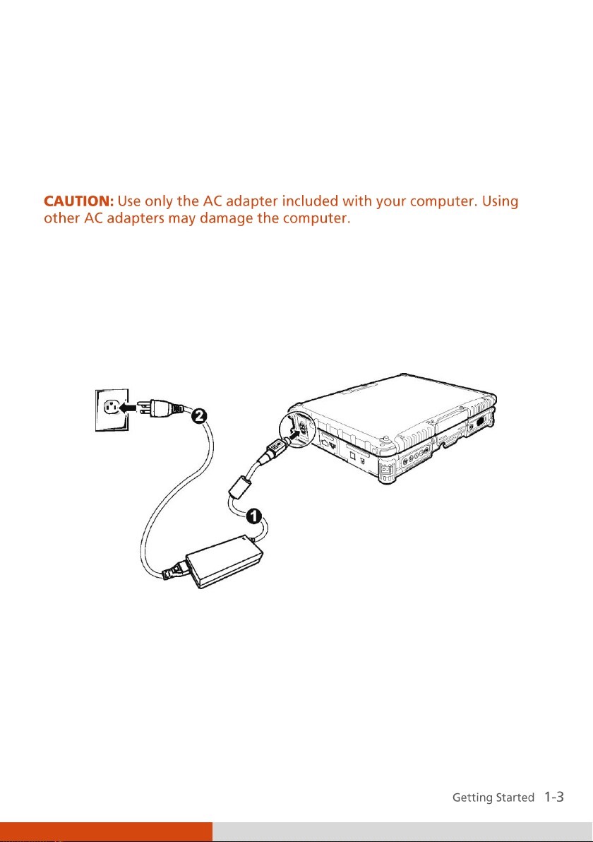
Connecting to AC Power
The computer operates either on the external AC power or internal battery
power. It is suggested that you use AC power when you start up the
computer for the very first time.
1. Make sure that the computer is turned off.
2. Plug the DC cord of the AC adapter to the power connector of the
computer ().
3. Plug the female end of the AC power cord to the AC adapter and the
male end to an electrical outlet ().
4. When the AC adapter is connected, power is being supplied from the
electrical outlet to the AC adapter and onto your computer. Now, you
are ready to turn on the computer.
Page 14
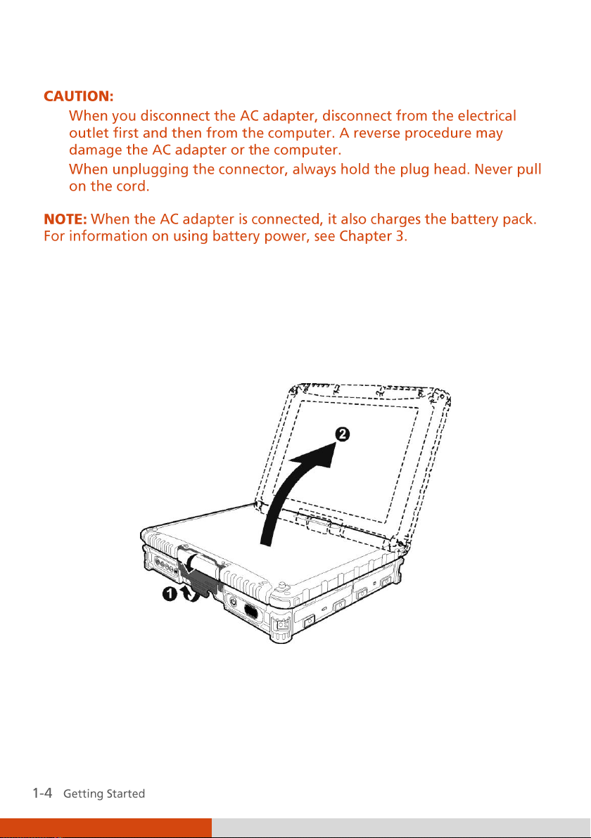
Latch A
Latch B
Opening and Closing the Cover
Open the top cover by pulling up on latch A and releasing latch B () and
lifting up the cover (). You can tilt the cover forward or backward for
optimal viewing clarity.
Close the top cover by closing the display (). Then position latch B on the
display side and bring latch A down () to fix the display in place.
Page 15

Latch A
Latch B
Page 16
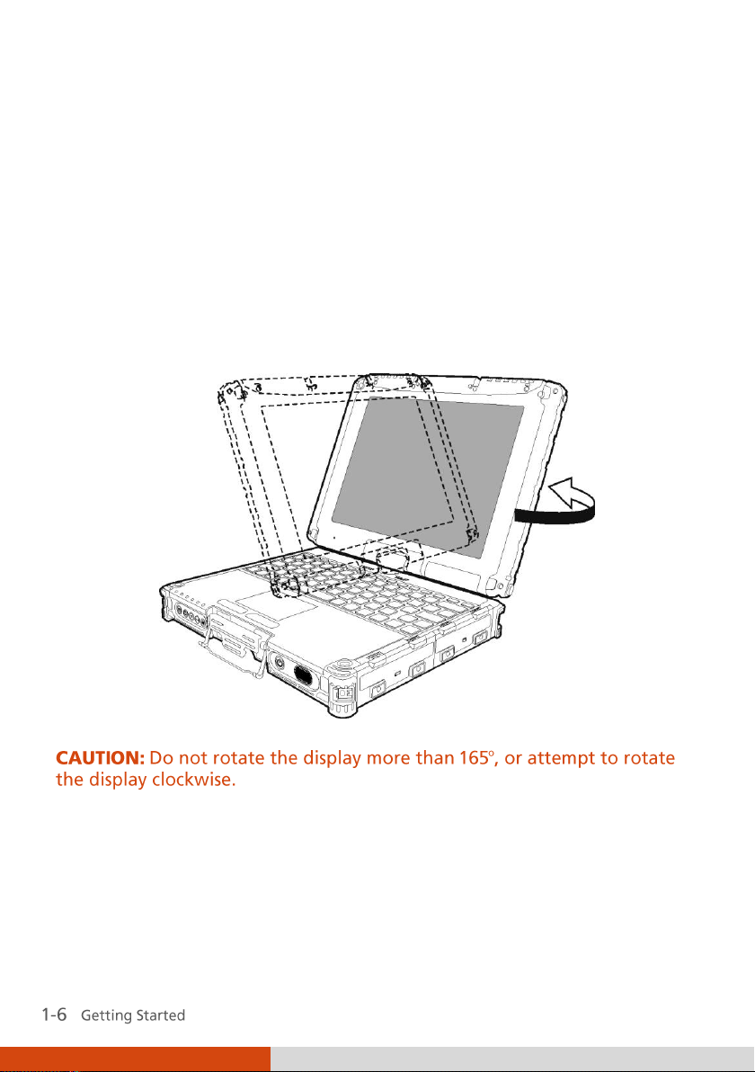
Operating in Tablet Mode
In addition to being used as a regular notebook computer (Laptop mode),
your computer can also be operated in Tablet mode. In Tablet mode, you
operate the computer with a stylus or digitizer pen, or a fingertip, instead of
a keyboard or mouse.
1. Open the top cover so that it is almost perpendicular with the keyboard
of the computer.
2. Turn the display counter-clockwise by 165
o
.
1. Close the computer with the display facing up (). Then pull up on the
latch A.
Page 17
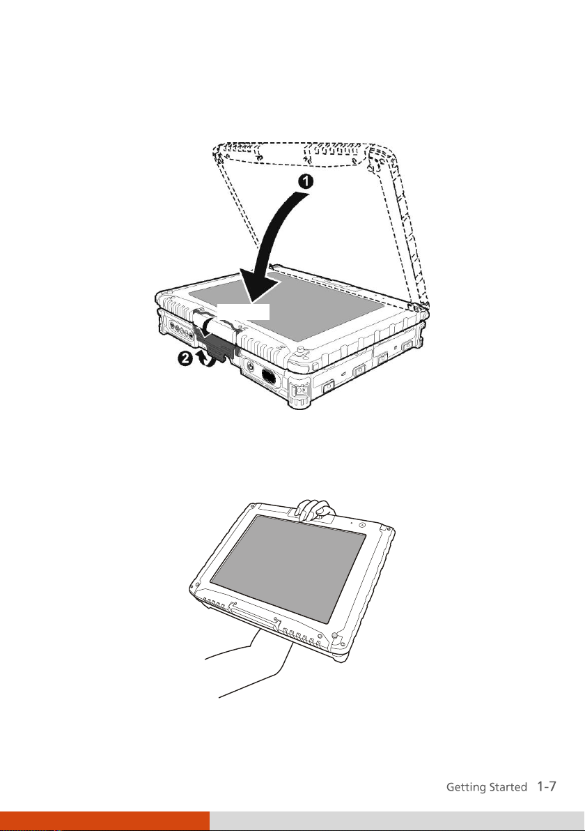
Latch A
Latch B
2. Position the latch B on the display side, then bring latch A down () to
fix the display in place.
In Tablet mode, the computer can be operated while holding it as shown. A
handgrip strap is supplied to help you hold the computer. (See “Attaching
the Handgrip Strap” in this chapter for installation instructions.)
To return to Laptop mode, perform the steps for changing the computer
into Tablet mode in reverse order.
Page 18
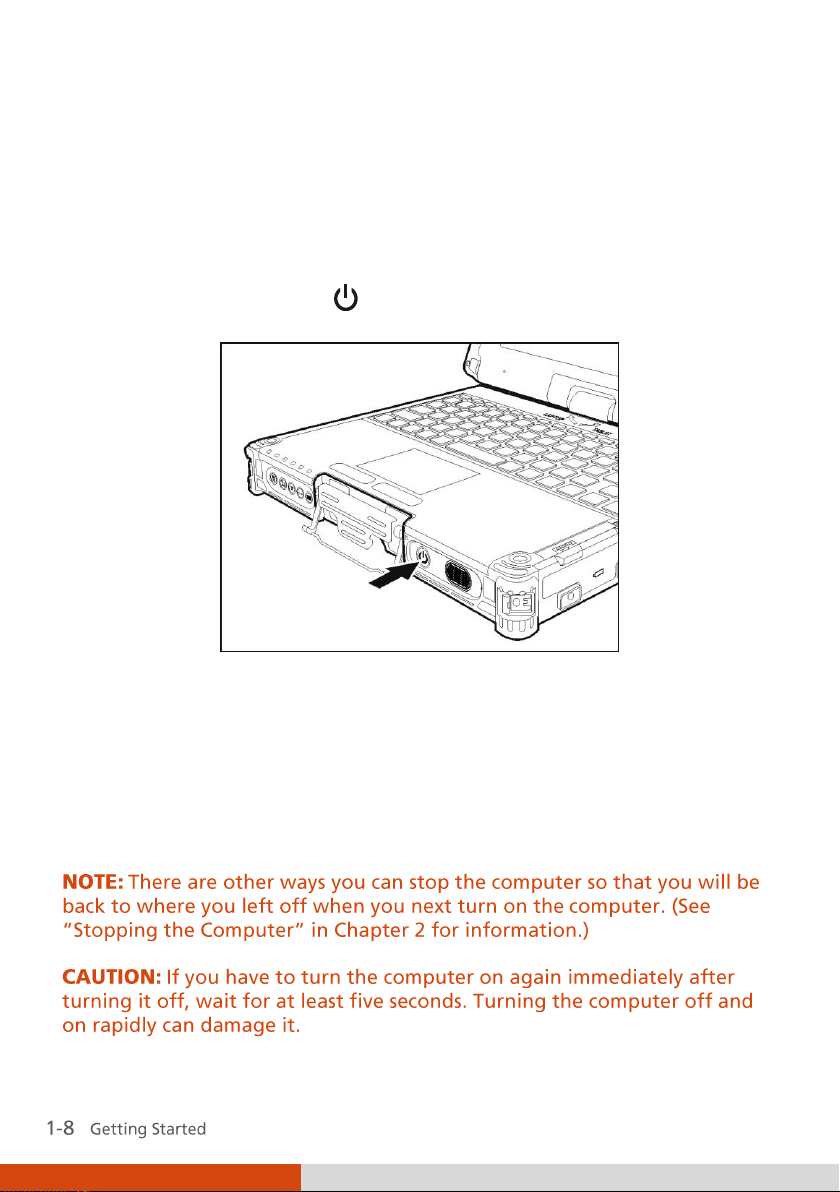
Turning On and Off the Computer
Turning On
1. Make sure that the computer is connected to AC power.
2. Press the power button (
3. Each time the computer is turned on, it performs a Power-On Self Test
(POST), and the operating system such as Windows should start.
).
Turning Off
To turn off the computer power, use the “Shut Down” command of your
operating system.
Page 19
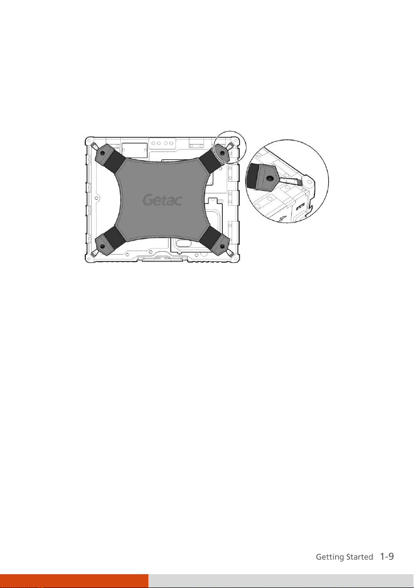
Attaching the Handgrip Strap
To use the handgrip strap, attach its four loops to the four bottom hooks on
your computer. Make sure the loops are securely hooked.
When you need to operate and hold your computer at the same time, insert
your hand through the strap for a firm grip.
Page 20
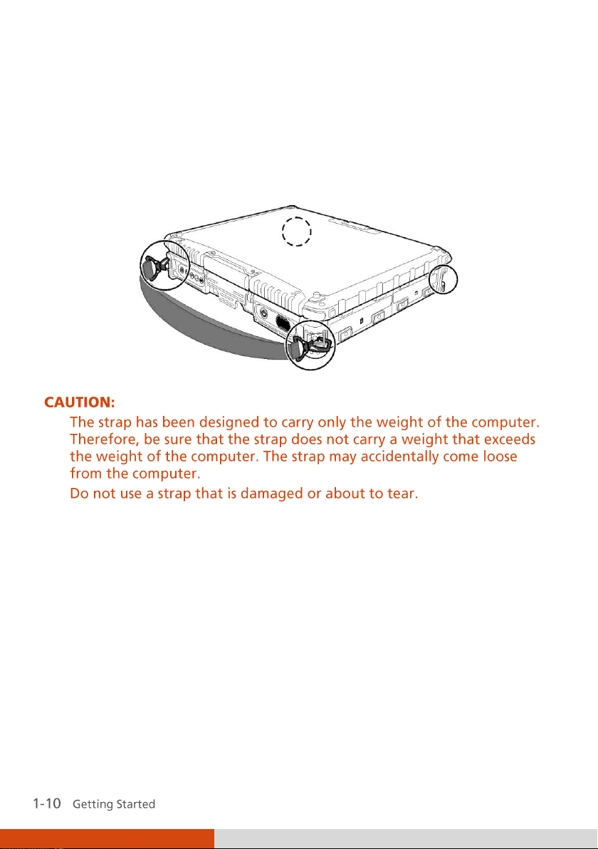
Attaching the Shoulder Strap
To use the shoulder strap, secure the snap hooks to the two buckles on your
computer. (Select models have four buckles for different positioning of the
strap.)
Page 21
Ref
Component
Description
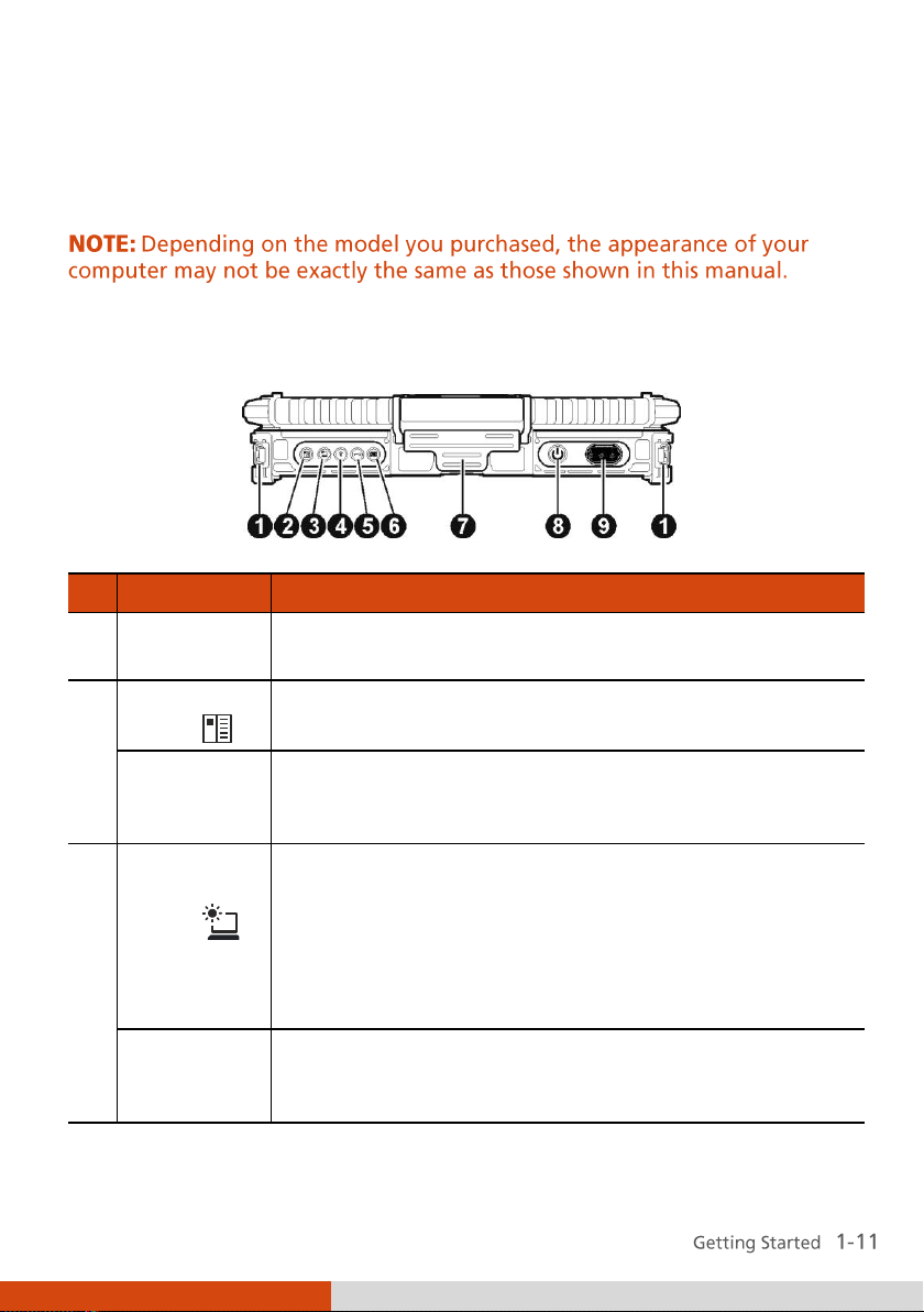
Strap Holder
Two buckles hold the shoulder strap. Four bottom
hooks hold the handgrip strap.
OSD Control
Button
Toggles the OSD (On Screen Display) control panel ON
and OFF.
P1
Can be re-defined using the Button Manager utility.
(See “Using Button Manager” in Chapter 7 for
information.)
Sunlightreadable
Button
Toggles the sunlight-readable function ON and OFF.
IMPORTANT: To prevent burns to your fingers if using
the computer (especially in Tablet Mode) with
sunlight-readable mode turned on, do wear gloves
when touching the top portion of the LCD display as it
may be hot to the touch.
P2
Can be re-defined using the Button Manager utility.
(See “Using Button Manager” in Chapter 7 for
information.)
Taking a Look at the Computer
Front Components
Page 22
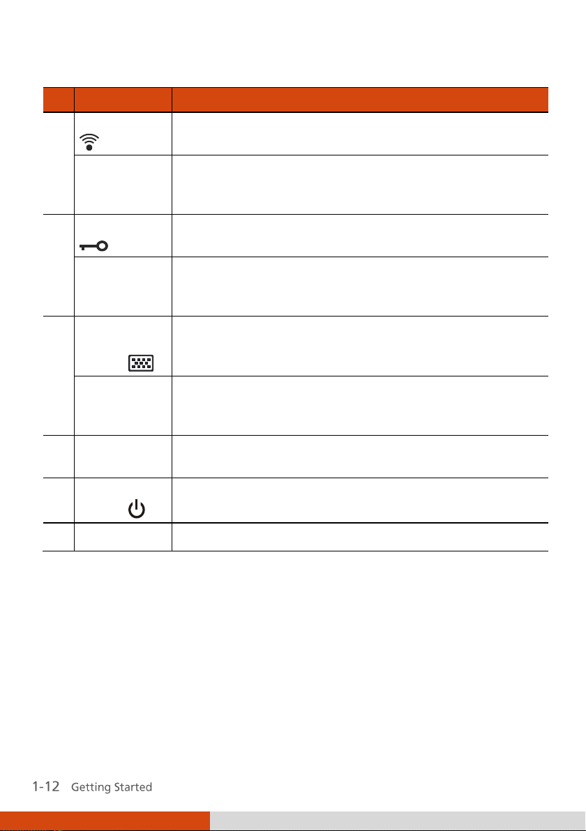
Ref
Component
Description
RF Button
Toggles the wireless LAN /Bluetooth/3G radio frequency
ON and OFF.
P3
Can be re-defined using the Button Manager utility.
(See “Using Button Manager” in Chapter 7 for
information.)
Reset Button
Serves as the Ctrl+Alt+Del keyboard keys.
P4
Can be re-defined using the Button Manager utility.
(See “Using Button Manager” in Chapter 7 for
information.)
Software
Keyboard
Button
Shows or hides the software keyboard on your LCD
display.
P5
Can be re-defined using the Button Manager utility.
(See “Using Button Manager” in Chapter 7 for
information.)
Top Cover
Latch
Locks the top cover.
Power
Button
Turns the computer power ON and OFF.
Speaker
Sends out sound and voice from your computer.
Page 23
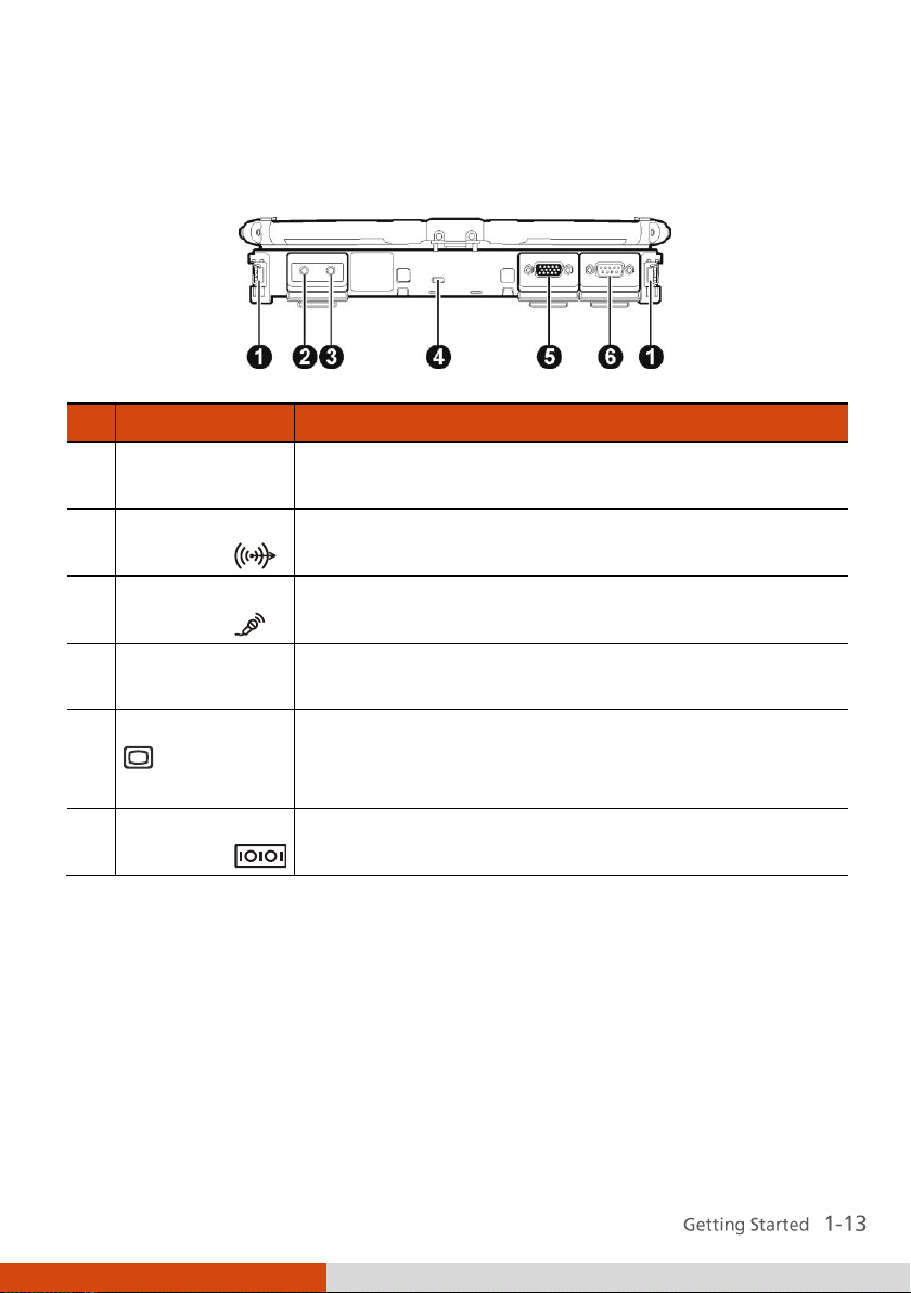
Ref
Component
Description
Strap Holder
Two buckles (option) hold the shoulder strap. Four
bottom hooks hold the handgrip strap.
Audio Output
Connector
Connects a set of headphones, external speakers
with amplifier, or an audio recording device.
Microphone
Connector
Connects an external microphone.
Kensington
Lock
Locks the computer to a stationary object for
security.
VGA Connector
Connects an external display monitor.
NOTE: Depending on your model, this port could be
a serial connector.
Serial
Connector
Connects a serial mouse or serial communication
device.
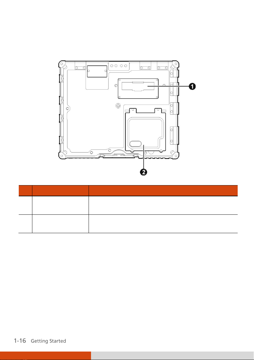
Rear Components
Page 24
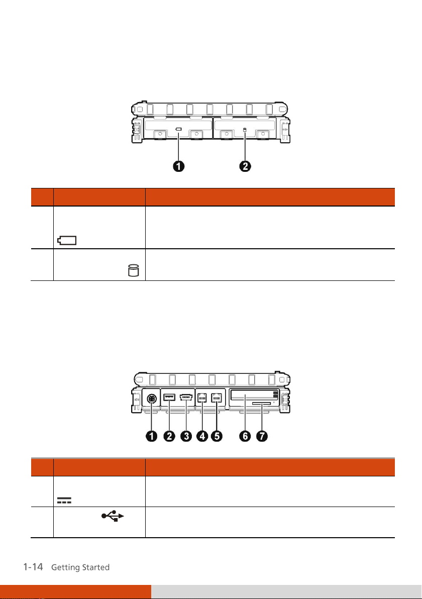
Ref
Component
Description
Battery Pack
Compartment
Inside is the battery pack that supplies power to
your computer when external power is not
connected.
Hard Disk Drive
Compartment
Inside is the hard disk drive.
Ref
Component
Description
Power Connector
Connects the AC adapter.
USB Port
Connects a USB device, such as a flash disk, printer,
digital camera, joystick, and more.
Right-Side Components
Left-Side Components
Page 25
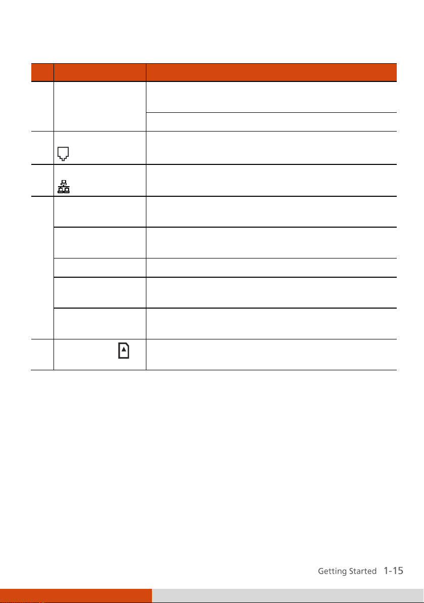
Ref
Component
Description
eSATA/USB
Combo Port
Connects an eSATA device such as an external hard
drive or optical drive.
Can also function as a USB port.
RJ-11 Connector
Connects the telephone line.
RJ-45 Connector
Connects the LAN cable.
ExpressCard Slot
(upper)
Accepts an ExpressCard for additional functions
(option).
PCMCIA Slot
(lower)
Accepts a PC card for additional functions.
or
PCMCIA Slot
(upper)
Accepts a PC card for additional functions.
Smart Card
Reader (lower)
Accepts a smart card for additional security feature
(option).
Card Reader
Accepts a SD (Secure Digital) card for removable
storage media.
Page 26
Ref
Component
Description
Expansion Bus
Connector
Inside is the expansion bus connector for using the
Port Replicator option.
Memory Slots
Inside are the memory slots for expanding the
memory size of your computer.
Bottom Components
Page 27
Ref
Component
Description
Webcam Lens
(option)
Allows you to use your computer’s camera function.
GPS Antenna
(option)
Inside is the antenna for receiving GPS signals.
WLAN Antenna
Inside is the antenna for wireless LAN (local area
network) transmission.
WWAN 3G
Antenna (option)
Inside is the antenna for optional wireless WAN
(wide area network) 3G transmission.
LCD Screen
Displays the output of the computer.
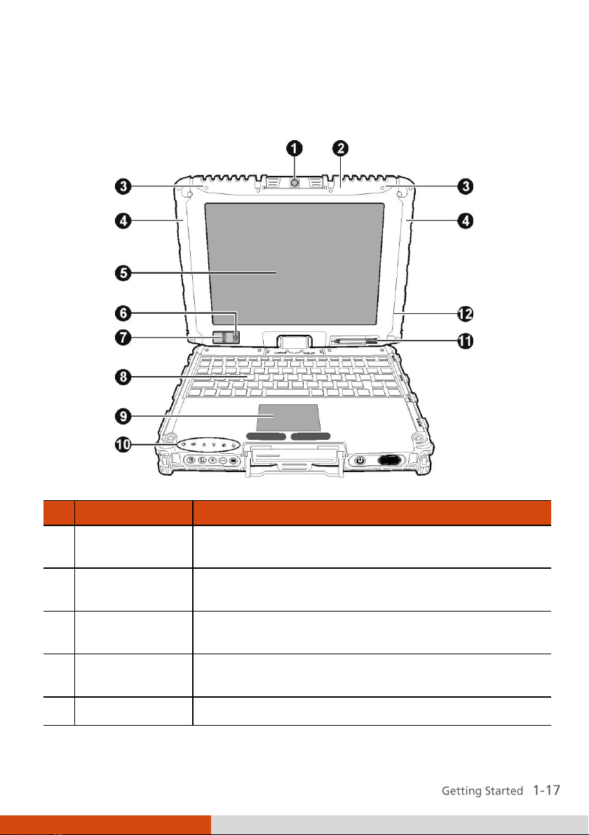
Top-open Components
Page 28
Ref
Component
Description
Light Sensor
Detects the surrounding lighting condition for
automatic adjustment of the LCD brightness and
optional keyboard backlight.
Fingerprint
Scanner (option)
Uses fingerprint verification to protect your
computer against unauthorized access.
Keyboard
Serves as the data input device.
Touchpad
Serves as the pointing device.
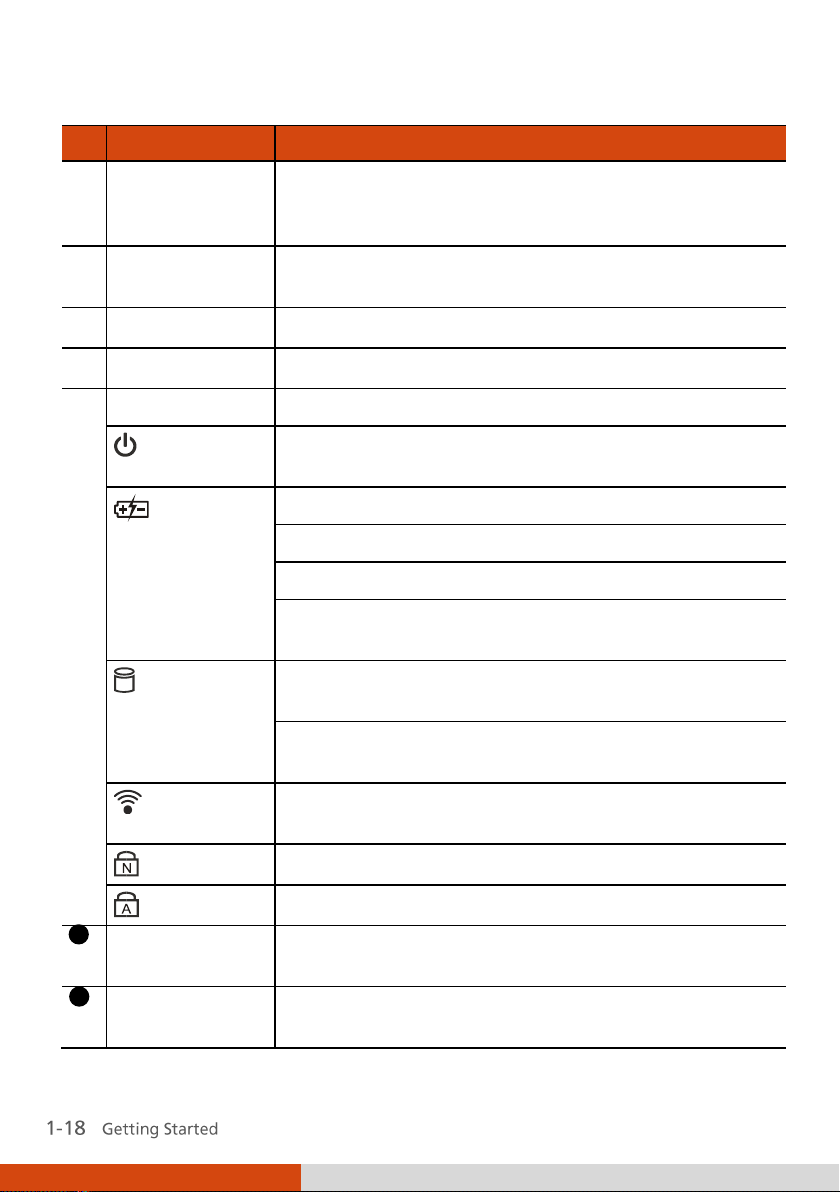
Indicators
Show the current status of the computer’s devices.
AC Power
Lights green when the computer is turned on and
using AC power.
Battery
Charge
Lights green when the battery is fully charged.
Lights yellow when the battery is being charged.
Blinks yellow when the battery’s capacity is below 10%.
Blinks green and yellow by turns when battery’s
temperature is too high (over 60oC).
Hard Disk
Drive In-Use
Lights green when the computer is accessing the
hard disk drive.
Lights red when the optional hard disk drive heater
is on for low temperature operation.
RF
Lights when the wireless LAN/Bluetooth/3G radio
frequency is on.
Num Lock
Lights when Num Lock is on.
Caps Lock
Lights when Caps Lock is on.
11
Stylus/Digitizer
Pen
Serves as the input device by tapping on the screen
to make selections and enter information.
12
Bluetooth
Antenna (option)
Inside is the antenna for optional Bluetooth feature
transmission.
Page 29
Chapter 2
Operating Your Computer
This chapter provides information about the use of the computer.
If you are new to computers, reading this chapter will help you learn the
operating basics. If you are already a computer user, you may choose to read
only the parts containing information unique to your computer.
Page 30
To stop in this
mode...
Do this...
To start up or
resume again
Off
Follow the shutdown procedure of
your operating system. This can
prevent loss of unsaved data or
damage to your software programs.
If the system is locked up because of
hardware or software problems, press
the power button to turn off the
computer.
Press the power
button.
Starting and Stopping the Computer
There are a number of ways to start and stop the computer.
Starting the Computer
You always start the computer using the power button.
A computer starts up with an operating system (OS) existing on the storage
device such as the hard disk. The computer will automatically load the OS
after you turn it on. This process is called booting.
Stopping the Computer
When you finish a working session, you can stop the computer by turning
off the power or leaving the computer in Standby/Sleep or Hibernation
mode:
Page 31

To stop in this
mode...
Do this...
To start up or
resume again
Standby/Sleep
Depending on your settings in
Windows, you can place the computer
in Standby/Sleep mode by:
Closing the display cover
Pressing the Fn+F10 hot key
Pressing the power button
Press any key.
Hibernation
Depending on your settings in
Windows, you can place the computer
in Hibernation mode by:
Closing the display cover
Pressing the power button
Press the power
button.
If you choose to stop in Standby/Sleep or Hibernation mode, you can return
to where you left off the next time you start up the computer. (See “Power
Management” in Chapter 3 for more information.)
Page 32

Using the Internal Keyboard
Your keyboard has all the standard functions of a full-sized computer
keyboard plus an Fn key added for specific functions.
The standard functions of the keyboard can be further divided into four
major categories:
Typewriter keys
Cursor-control keys
Numeric keys
Function keys
Typewriter Keys
Typewriter keys are similar to the keys on a typewriter. Several keys are
added such as the Ctrl, Alt, Esc, and lock keys for special purposes. When the
lock keys ( aps Lock and Num Lk) are pressed, their corresponding indicators
light up.
The Control (Ctrl) / Alternate (Alt) key is normally used in combination with
other keys for program-specific functions. The Escape (Esc) key is usually
used for stopping a process. Examples are exiting a program and canceling a
command. The function depends on the program you are using.
Cursor-Control Keys
Cursor-control keys are generally used for moving and editing purposes.
They are Home, End, Page Up, and Page Down. When used with Fn key, they
become Left, Right, Up, and Down arrow keys.
Page 33

Numeric Keypad
A 15-key numeric keypad is embedded in the typewriter keys as shown next:
Numeric keys facilitate entering of numbers and calculations. When Num
Lock is on, the numeric keys are activated; meaning you can use these keys
to enter numerals.
Fn
Page 34

Key
Description
Switches the keyboard backlight on and off (optional).
Switches the wireless LAN radio on and off.
NOTE: This function works only if an optional mini PCI-E
wireless LAN card is installed.
Decreases the sound volume.
Increases the sound volume.
Function Keys
On the top row of the keys are the function keys: to . Function keys
are multi-purpose keys that perform functions defined by individual
programs.
Fn Key
The key, at the lower left corner of the keyboard, is used with another
key to perform the alternative function of a key. The letter “Fn” and the
alternative functions are identified by the color of blue on the keytop. To
perform a desired function, first press and hold , then press the other key.
Hot Keys
Hot keys refer to a combination of keys that can be pressed any time to
activate special functions of the computer. Most hot keys operate in a cyclic
way. Each time a hot key combination is pressed, it shifts the corresponding
function to the other or next choice.
You can easily identify the hot keys with the icons imprinted on the keytop.
The hot keys are described next.
Page 35

Key
Description
Decreases the LCD brightness (20 levels).
Increases the LCD brightness (20 levels).
Switches the system sound output off (mute) and on.
Switches LCD backlight on and off.
Switches the display output when external devices are
connected.
NOTE: This function only applies to Plug & Play display
devices.
Serves as the sleep button that you can define with
Windows’ Power Options. (See the “Power Management”
in Chapter 3.)
Windows Keys
The keyboard has two keys that perform Windows-specific functions:
Windows Logo key and Application key.
The Windows Logo key opens the Start menu and performs
software-specific functions when used in combination with other keys. The
Application key usually has the same effect as a right mouse click. (See
your Windows manual for more information.)
Page 36

Using the Software Keyboard
When using the computer in Tablet mode, you can use the software
keyboard.
1. Press the software keyboard button ( ) and the software keyboard
will appear onscreen.
(The above is for reference only. The actual one depends on your
Windows version.)
2. Enter the characters with the stylus.
NOTE:
Page 37

Using the Touchpad
The touchpad is a pointing device that allows you to communicate with the
computer by controlling the location of the pointer on the screen and
making selection with the buttons.
The touchpad consists of a rectangular pad (work surface) and a left and
right buttons. To use the touchpad, place your forefinger or thumb on the
pad. The rectangular pad acts like a miniature duplicate of your display. As
you slide your fingertip across the pad, the pointer (also called cursor) on the
screen moves accordingly. When your finger reaches the edge of the pad,
simply relocate yourself by lifting the finger and placing it on the other side
of the pad.
Here are some common terms that you should know when using the
touchpad:
Page 38

Term
Action
Point
Move your finger on the pad until the cursor points to the
selection on the screen.
Click
Press and release the left button.
–or–
Tap gently anywhere on the pad.
Double-click
Press and release the left button twice in quick succession.
–or–
Tap twice on the pad rapidly.
Drag and
drop
Press and hold the left button, then move your finger until
you reach your destination (drag). Finally, release the
button (drop) when you finish dragging your selection to
the destination. The object will drop into the new location.
–or–
Gently tap twice on the pad and on the second tap, keep
your finger in contact with the pad. Then, move your
finger across the pad to drag the selected object to your
destination. When you lift your finger from the pad, the
selected object will drop into place.
Scroll
To scroll is to move up and down or left and right in the
working area on the screen.
To move vertically, place your finger on the right or left
edge of the pad and slide your finger up and down along
the edge. To move horizontally, place your finger on the
top or bottom edge of the pad and slide your finger left
and right.
This function works only after you install the touchpad
driver supplied with the computer and it may not work for
all applications.
TABLE NOTE: If you swap the left and right buttons, “tapping” on the
touchpad as an alternative method of pressing the left button will no longer
be valid.
Page 39

Configuring the Touchpad
You may want to configure the touchpad to suit your needs. For example, if
you are a left-handed user, you can swap the two buttons so that you can
use the right button as the left button and vice versa. You can also change
the size of the on-screen pointer, the speed of the pointer, and so on.
To configure the touchpad, go to Control Panel Mouse Properties.
Page 40

Navigating on the Screen
The screen of your computer is touch-sensitive. You can control the location
of the cursor/pointer on the screen using your finger or the included stylus
or digitizer pen to communicate with the computer.
IdeaCom Calibration
CalTouch
Using the Touchscreen
If your computer is equipped with the touchscreen feature, you can use your
finger or the included stylus to navigate and select objects on the screen.
Page 41

Term
Action
Click/Point
Tap gently on the touchscreen.
Double-click
Tap twice on the touchscreen rapidly.
Drag and
drop
Tap lightly on the touchscreen and move your finger
until you reach your destination (drag). Finally, release
your finger (drop) when you finish dragging your
selection to the destination. The object will drop into
the new location.
Gestures
Actions
( = finger down; = finger up)
Descriptions
Pan
(Scroll)
or
Drag 1 or 2 fingers up or down.
Use panning to see
another part of a page
that has scroll bars.
Here are some common terms that you should know when using the
touchscreen:
Using Multi-touch Gestures (Windows 7 Only)
If your computer model comes with multi-touch-capable screen and
Windows 7, you can interact with your computer by placing two fingers on
the screen. The movement of the fingers across the screen creates
“gestures,” which send commands to the computer.
Here are the multi-touch gestures that you can use:
Page 42

Gestures
Actions
( = finger down; = finger up)
Descriptions
Zoom
(Pinch)
Move two fingers apart/toward each
other.
Use zooming to make
an item (a photo for
example) on the screen
larger or smaller. The
gesture works in
applications that
support mouse wheel
zooming.
Rotate
or
Move two fingers in opposing
directions.
-orUse one finger to pivot around
another.
Use rotating to move a
picture or other item
on the screen in a
circular direction
(clockwise or counterclockwise). The gesture
works in applications
that support the
specific gesture.
Press and
Tap
Press on target and tap using a
second finger.
Use press and tap to
access the shortcut
menu.
Page 43

Gestures
Actions
( = finger down; = finger up)
Descriptions
Twofinger
Tap
Tap two fingers at the same time
(where the target is in the midpoint
between the fingers).
The function is defined
by applications that
support the specific
gesture.
Flicks
Make quick drag gestures in the
desired direction.
Flick left or right to
navigate back and
forward in a browser
and other
applications. The
gesture works in most
applications that
support back and
forward.
Page 44

Using the Dual Mode Display (Optional)
Dual mode display incorporates both touchscreen and digitizer functions.
The display is set to Touchscreen mode by default. Touchscreen mode
provides all the functionalities that an ordinary touchscreen has. When the
computer receives signals from the active digitizer pen, the display
automatically switches to Digitizer mode.
When using the digitizer pen, be sure to install the included size “AAAA”
battery.
Here are some common terms that you should know when using the active
digitizer feature:
Page 45

Term
Action
Wake up
The digitizer pen automatically enters
Sleep mode after 30 seconds of inactivity.
To start using the pen, tap the tip of the
pen to activate it.
Move
Move the cursor pointed by the digitizer
pen.
Click/Point
Tap gently on the display.
Double-click
Tap twice on the display rapidly.
Drag and
drop
Tap lightly on the display and move your
digitizer pen until you reach your
destination (drag). Finally, release your
digitizer pen (drop) when you finish
dragging your selection to the
destination. The object will drop into the
new location.
Right-click
Press and hold down the digitizer pen
button (A), then tap gently the object.
Page 46

Page 47

Using the Hard Disk Drive
Your computer comes with a removable 2.5-inch SATA (serial ATA) hard disk
drive.
You can enable AHCI (Advanced Host Controller Interface), a programming
interface for SATA host controllers. AHCI defines transactions between the
SATA controller and software and enables advanced performance and
usability with SATA. When the SATA AHCI mode is enabled, your system can
support SATA native command queuing, aggressive power management,
and so on.
Select models are equipped with a hard disk heater that automatically turns
on for low temperature operation.
Page 48

Using OSD Control Panel
The OSD Control Panel allows you to easily activate or operate certain
functions on your computer.
To use the OSD Control Panel:
1. Press the button
2. The following screen appears, providing several control buttons.
on the front of your computer.
For detailed descriptions of the Control Panel, click the
3. To close the Control Panel, either press the button
again or click the
button .
button.
on your computer
Page 49

Using the Fingerprint Scanner (Optional)
The fingerprint scanner provides a strong authentication mechanism based
on fingerprint recognition. You can log on to your computer or sign in to a
web site with your fingerprint instead of a password. You can also encrypt
files and folders with your fingerprint.
To register your fingerprint, click Start All Programs Fingerprint
Software Fingerprint Registration. Click the finger you want to register
and follow the onscreen instructions to complete.
Page 50

You can then use the Fingerprint Software to set up how the fingerprint
authentication works.
For detailed information, click Start All Programs Fingerprint Software
Help.
Page 51

Using the Video Features
The video subsystem of your computer features:
10.4-inch wide TFT (Thin-Film Transistor) color LCD display with
1024×768 XGA resolution
Simultaneous display on LCD and external monitor, which is useful when
you have a presentation as you can control the screen from your
computer and face the audience at the same time (option)
Multi-display capability, which allows you to expand your desktop on the
screen to another display device so that you have more desktop space to
work on
Built-in light sensor to automatically adjust the LCD brightness and
optional keyboard backlight
Power Management
Sunlight-readable LCD display
Page 52

Configuring the Display Modes
Your computer has been set to a default resolution and number of colors
before shipment. You can view and change display settings through your
operating system. See your operating system documentation or online help
for specific information.
For displaying in higher resolutions, you can connect an external monitor
that supports higher resolutions. (See “Connecting an External Monitor” in
Chapter 4 for more information.)
Using Landscape or Portrait View
After Windows is started up, you can rotate the display and perform the
touchscreen and active digitizer operations in the rotated mode.
To rotate the display, press the button located on the front of your
computer to open the OSD control panel and click . Each time
this Rotate button is clicked, the screen display rotates counter-clockwise by
90O.
Page 53

Primary
Landscape
Primary
Portrait
Secondary
Landscape
Secondary
Portrait
Primary
Landscape
Primary
Landscape
Primary
Portrait
Secondary
Landscape
Primary
Landscape
Display
Display
Display
Display
Display
Display
Display
Display
Display
For a Model without 3G Module
For a Model with 3G Module
Page 54

Using the Audio Features
The audio subsystem of your computer features:
Built-in sound system for recording and playing sound on your computer
Azalia interface (high density audio codec)
Built-in Speaker
External audio connectors
Ways of playing and recording sound vary with the operating system used.
See your operating system documentation or online help for specific
information.
Page 55

Connecting Audio Devices
For higher audio quality, you can send or receive sound through external
audio devices.
Audio Output Connector (
) can be connected to speakers,
headphones, or earphone set.
Microphone Connector (
) can be connected to an external
microphone for recording voice or sound.
Page 56

Mode
Current settings
Setting buttons for
different modes
Using G-Camera Lite
G-Camera Lite allows you to take pictures with the Webcam, if supplied with
your computer.
To start G-Camera Lite, click Start All Programs G-Camera Lite
G-Camera Lite. The camera control panel appears.
Click the Shutter button
For detailed descriptions of G-Camera Lite, click the button .
or press Enter to take photos.
Page 57

Using the Communication Features
Using the Modem
The internal 56 K fax/data modem allows you to use the telephone line to
communicate with others by fax, email, or connect to an online service or
bulletin board.
To connect the telephone line to the modem, connect one end of the
modem cable to the RJ-11 connector on the computer and the other end to
the phone line.
Page 58

Using the LAN
The internal 10/100/1000Base-T LAN (Local Area Network) module allows
you to connect your computer to a network. It supports data transfer rate up
to 1000 Mbps.
To connect the network cable to the LAN module, connect one end of the
LAN cable to the RJ-45 connector on the computer and the other end to the
network hub.
Page 59

Technology
802.11a
802.11g
802.11n
Stated Maximum
Throughput (Mbps)
54
54
100 Mbps or more
Data Rates (Mbps)
54, 48, 36, 24, 18,
12, 9, 6
54, 36, 18, 9
100 ~ 210
Band (GHz)
5.15 ~ 5.35
2.4
2.4 / 5
Modulation
Technology
OFDM (Orthogonal
Frequency Division
Multiplexing)
OFDM
(Orthogonal
Frequency Division
Multiplexing)
Spatial
multiplexing, uses
MIMO (multipleinput multipleoutput)
Using the Wireless LAN
Depending on your model, an internal mini PCI-E wireless LAN (WLAN) card
may have been pre-installed by your computer manufacturer at the factory.
This card allows you to access corporate networks or the Internet in a
wireless environment.
The WLAN features include:
Peer-to-Peer (Ad-Hoc) and Access Point (Infrastructure) modes support
WEP (Wired Equivalent Privacy) 64/128-bit data encryption
IEEE 802.11a/g/n standard compliance
To take advantage of the WLAN feature, make sure that the WLAN driver is
installed correctly. If your WLAN card was provided by your dealer instead of
the computer manufacturer, contact your dealer for the correct driver to
use.
Page 60

Turning Off/On the WLAN Radio
Your computer has a built-in Fn+F2 WLAN hot key to switch the WLAN
on/off. If you need to temporarily turn off the radio, press Fn+F2. To resume
network connection, press Fn+F2 again.
It takes approximately 30 seconds for your computer to make a successful
WLAN connection and approximately 10 seconds to disconnect.
Connecting to a Wireless Network
To connect to a wireless network:
1. Make sure that the WLAN radio is on (controlled by Fn+F2).
2. Click Start Programs Intel PROSet Wireless Intel PROSet
Wireless.
3. If any wireless network is detected, the following window appears on
screen.
Page 61

Status
Icon
On
(blue with white logo).
Connected
(blue with green logo)
4. Click to select a wireless network to connect to, and then click Connect.
5. Depending on the settings, you may be asked to enter a wireless security
password (encryption key).
For more information on the Intel PROSet Wireless utility, click Help? in the
Intel(R) PROSet/Wireless window.
Using the Bluetooth Feature (Optional)
Depending on your model, your computer may incorporate the Bluetooth
capability for short-range (about 10 meters) wireless communications
between devices without requiring a cable connection.
With Bluetooth, data can be transmitted through walls, pockets and
briefcases as long as two devices are within range. By default, your
computer’s Bluetooth feature is active (always ON) upon booting your
computer and is in the general discoverable and pairable mode.
The status of the Bluetooth connection is indicated by the Bluetooth icon
located in the taskbar in the lower-right part of the screen.
You can use the Bluetooth Utility to configure Bluetooth connection settings
and transfer files.
Connecting to another Bluetooth Device
1. Make sure that the target Bluetooth device is turned on, discoverable
and within close range. (See the documentation that came with the
Bluetooth device.)
Page 62

2. To search for Bluetooth devices, use any of the following three methods:
Method 1:
Right click the Bluetooth icon located in the taskbar in the lower-right
part of the screen. Select Explore Bluetooth Places.
Method 2:
Right click the Bluetooth icon located in the taskbar in the lower-right
part of the screen. Select Display Classic View. The Bluetooth utility
screen appears. Right click the central icon (the yellow sun) and select
Search Devices.
Page 63

Method 3:
Use Windows File Manager to browse to Bluetooth Places and select
Search Devices.
3. Select the device you want to connect from the search results.
4. Depending on the type of Bluetooth device that you want to connect to,
you will need to enter the pertinent information.
For detailed information on using the Bluetooth Utility, see the Bluetooth
Utility Help
Page 64

Using the GPS
GPS (Global Positioning System) is a constellation of 24 well-spaced satellites
that orbit the Earth and make it possible for devices enabled with GPS
receivers to pinpoint their location.
You need to install third-party GPS navigation software to take advantage of
the GPS feature.
Page 65

Chapter 3
Managing Power
Your computer operates either on external AC power or on internal battery
power.
This chapter tells you how you can effectively manage power. To maintain
optimal battery performance, it is important that you use the battery in the
proper way.
Page 66

AC Adapter
The AC adapter serves as a converter from AC (Alternating Current) to DC
(Direct Current) power because your computer runs on DC power, but an
electrical outlet usually provides AC power. It also charges the battery pack
when connected to AC power.
The adapter operates on any voltage in the range of 100~240 V AC.
Page 67

Battery Pack
The battery pack is the internal power source for the computer. It is
rechargeable using the AC adapter.
The operating time of a fully charged battery pack depends on how you are
using the computer. When your applications often access peripherals, you
will experience a shorter operating time.
NOTE: Care and maintenance information for the battery is provided in the
“Battery Pack Guidelines” section in Chapter 7.
Charging the Battery Pack
NOTE:
z Charging will not start if the battery’s temperature is below 0°C (32°F)
or above 40°C (104°F).
z The charging process will stop and the Battery Charge Indicator flashes
green and yellow by turns when the battery’s temperature gets above
60°C (140°F). If this happens, the battery pack may be damaged. Please
contact your dealer.
z During charging, do not disconnect the AC adapter before the battery
has been fully charged; otherwise you will get a prematurely charged
battery.
To charge the battery pack, connect the AC adapter to the computer and an
electrical outlet. The Battery Charge Indicator (
yellow to indicate that charging is in progress. You are advised to keep the
computer power off while the battery is being charged. When the battery is
fully charged, the Battery Charge Indicator is off.
) on the computer glows
It takes approximately 3 hours to fully charge the Li-Ion battery pack when
the computer is off, and approximately 6 hours to fully charge the Li-Ion
battery pack when the computer is on.
Managing Power 3-3
Page 68

Switch
Checking the Battery Level
By Operating System
You can check the approximate battery level using the battery meter
function of the operating system. To read the battery level in Windows, click
the battery icon on the taskbar.
By Gas Gauge
On the exterior side of the battery pack is a gas gauge for displaying the
estimated battery charge. When the battery pack is not installed in the
computer and you want to know the battery charge, you can press the
switch with a pointed device to see the corresponding value of indicator
segment that light green.
Page 69

The value of the corresponding green segment indicates the relative
percentage of the battery charge. The battery pack is fully discharged when
you see no segment glowing green.
Replacing the Battery Pack
If you often rely on battery power for a long period of time while traveling,
you may consider the purchase of an additional battery pack from your
dealer and keep it with you in a fully charged state as a backup.
To replace the battery pack, follow these steps:
1. Make sure that the computer is not turned on or connected to AC
power.
2. Locate the battery compartment on the right side of the computer.
3. Open the compartment cover by pressing on both sides of the release
latch using your thumb and index fingers.
Page 70

4. Pull on the ribbon strip to remove the battery pack.
5. Slide the new battery pack all the way into the slot. Make sure to
observe the correct orientation (the ribbon strip must face outward for
future battery back removal).
6. Close the compartment cover to secure the battery pack.
Page 71

Battery Low Signals and Actions
When the battery is low, Windows gives warning messages and the Battery
Charge Indicator ( ) blinks yellow to alert you.
Immediately save your data upon Battery Low. The remaining operating
time depends on how you are using the computer. If you are using the audio
subsystem, PC card, hard or USB flash disk, the battery might run out of
charge very quickly.
Always respond to Battery Low by connecting the AC adapter, turning off
the computer, or placing your computer in Hibernation mode. If you do not
take any action, the computer will automatically hibernate and turn off.
Power Options
Page 72

What...
When...
Power to the hard disk is turned
off
When the hard disk has been idle for a
set period.
Power to the display is turned off
When the display has been idle for a
set period.
The computer enters the
Standby/Sleep mode. The hard
disk and display are turned off
and the entire system consumes
less power.
When the entire system has been idle
for a set period.
When you press the Fn+F10 hot key. *
When you close the cover. *
When you press the power button. *
The computer enters the
Hibernation mode. (See the next
subsection for more
information.)
When you press the Fn+F10 hot key. *
When you close the cover. *
When you press the power button. *
Power Management
Your computer supports ACPI (Advanced Configuration and Power
Interface) for power management. The power management feature allows
you to reduce the power consumption for energy saving.
With an ACPI-compliant operating system such as Windows, power supply to
different computer components is controlled on an as-needed basis. This
allows maximum power conservation and performance at the same time.
In general, Windows’ power management works in this way:
* Depends on your settings in Windows.
For detailed information on power management, see Windows’ Help.
Page 73

Hibernation
Hibernation is a very useful feature. People frequently open many
applications when they use computers. It takes some time to get all these
applications open and running, and normally they all have to be closed
before the computer can be turned off.
When you use the hibernation feature, you do not have to close the
applications. The computer stores the state of your computer to a file on the
hard disk and then shuts down. The next time you turn on your computer,
you return to exactly where you left off.
Page 74

Power-Saving Tips
Aside from enabling your computer’s power saving mode (see previous
section), you can do your part to maximize the battery’s operating time by
following these suggestions.
Do not disable Power Management.
Decrease the LCD brightness to the lowest comfortable level.
Shorten the length of time before Windows turn off the display.
Many USB devices use power just by being connected. If you use a USB
mouse, you can save power by disconnecting the mouse and using the
touchpad. If you use a USB flash drive, unplug it when you are not using
it.
If you work with an application that uses a PC card, exit the application
when you finish using it.
If you have a PC card installed, remove it when not in use. Some PC cards
drain power even while they are inactive.
Turn off the wireless radio if you are not using the wireless module.
Turn off the computer when you are not using it.
Page 75

Chapter 4
Expanding Your Computer
You can expand the capabilities of your computer by connecting other
peripheral devices. When using a device, be sure to read the instructions
accompanying the device together with the relevant section in this chapter.
Page 76

Connecting an External Monitor (Optional)
If you want the benefits of a larger display screen with higher resolution,
you can connect an external display monitor to your computer. Follow this
procedure to connect an external monitor:
1. Make sure that the computer is not turned on.
2. Plug the monitor’s D-type signal connector to the computer’s VGA
connector.
3. Plug one end of the monitor’s power cord into the power socket on the
monitor and the other end to an electrical outlet.
4. To use the monitor, turn on the monitor before turning on the computer.
5. The monitor should respond by default. If not, you can switch the display
to the monitor or to both (simultaneous display), or to multi-display by
pressing the Fn+F9 hot key. In Windows, you can also change the display
through the settings in Display Properties.
6. You can change display settings through your operating system. See
your operating system documentation or online help for specific
information.
Page 77

Connecting a Serial Device
Your computer has one or two serial port (depending on model) for
connecting a serial device such as a serial mouse or serial communication
device (modem).
Follow this procedure to connect a serial device:
1. Make sure the computer is not turned on
2. Plug the device cable to the serial port on the rear of the computer.
3. Turn on the computer.
Page 78

Connecting a USB Device
Your computer has a USB port for connecting USB devices, such as a digital
camera, scanner, printer, modem, and mouse.
The USB port support transfer rates up to 12 MB/s for USB 1.1 devices and
480 MB/s for USB 2.0 devices.
To connect a USB device, simply plug the device cable to one of the USB
ports.
Page 79

Connecting an eSATA Device
Your computer has an eSATA/USB Combo port for connecting eSATA devices
(such as an external hard drive and external optical drive) / USB devices (see
previous section).
The port supports SATA II with transfer rate up to 3.0Gbit/s. It can provide 5V
power if a certified USB-eSata combo cable is used.
To connect an external eSATA device, simply plug the device cable to the
eSATA port.
Page 80
Eject button
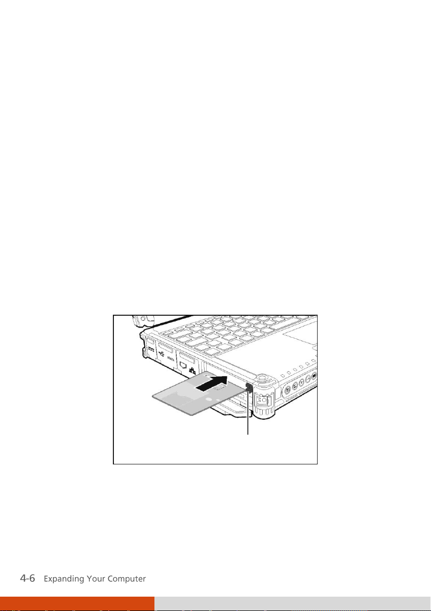
Using Smart Cards (Optional)
Your computer may have a smart card slot for additional security feature,
providing tamper-proof storage of user and account identity. A smart card is
a type of plastic card embedded with a computer chip that stores and
transacts data between you (user) and the computer.
You need to install third-party smart card software to take advantage of the
smart card feature.
Inserting and Removing a Smart Card
To insert a smart card:
1. Locate the smart card slot.
2. Slide the smart card, with its label and embedded computer chip facing
up into the slot.
3. When a new card is seated, use the third-party smart card software to
allow your computer to read it.
Page 81

To remove a smart card:
1. Make sure that the third-party smart card software is not accessing the
smart card.
2. Pull the card out of the slot.
Page 82

Eject button
Using PC Cards
Your computer has one or two PC card slots that support CardBus
specifications. The slots can accommodate a type II card. Typical type II cards
are flash memory, SRAM, modem, LAN, and SCSI cards.
Inserting and Removing a PC Card
To insert a PC card:
1. Locate the PC card slot on the left side of the computer.
2. Slide the PC card, with its label facing up, into the slot until the eject
button pops out.
Page 83

3. When a new card is seated, the computer will detect it and try to install
the appropriate driver. Follow the on-screen instructions to complete the
process.
To remove a PC card:
1. Double-click on the Safely Remove Hardware icon ( for Windows
Vista/Windows 7 or for Windows XP) found on the Windows taskbar
and the Safely Remove Hardware window appears on screen.
2. Select (highlight) the PC card from the list to disable the card.
3. Push the eject button and the card will slide out slightly.
4. Pull the card out of the slot.
Page 84

Using ExpressCards (Optional)
Your computer may have an ExpressCard slot.
ExpressCard supports the PCI Express and USB 2.0 serial data interfaces
(supporting speeds of up to 2.5 Gbps and 480 Mbps respectively), improving
speed in data transfer while conserving power usage.
ExpressCard Type
The ExpressCard slot can accommodate a 54 mm (ExpressCard/54) or
34 mm (ExpressCard/34) wide ExpressCard. Typical ExpressCards support a
very extensive range of applications including memory, wired and wireless
communication cards, and security devices.
Shown next are the appearances of ExpressCards for your reference.
ExpressCard/54 ExpressCard/34
Page 85

Eject button
Inserting and Removing an ExpressCard
To insert an ExpressCard:
1. Locate the ExpressCard slot on the left side of the computer.
2. Slide the ExpressCard, with its label facing up, all the way into the slot
until the rear connectors click into place.
3. When a new card is seated, the computer will detect it and try to install
To remove an ExpressCard:
1. Double-click on the Safely Remove Hardware icon ( for Windows
2. Select (highlight) the ExpressCard from the list to disable the card.
3. Push the eject button and the card will slide out slightly.
4. Pull the card out of the slot.
the appropriate driver. Follow the on-screen instructions to complete the
process.
Vista/Windows 7 or for Windows XP) found on the Windows taskbar
and the Safely Remove Hardware window appears on screen.
Page 86

Using the Card Reader
Your computer has a Card Reader. The Card Reader is a small drive for
reading from and writing to removable storage cards (or called memory
cards). The Card Reader supports Secure Digital (SD) cards.
To insert a storage card:
1. Locate the Card Reader slot on the left side of the computer.
2. Align the card with its connector pointing to the slot and its label facing
up. Slide the card into the slot until it reaches the end.
3. Windows will detect the card and assign it a drive name.
To remove a storage card:
1. Double-click My Computer.
Page 87

2. Right-click the drive with the card and select Eject.
3. Pull the card out of the slot.
Page 88

Using the Port Replicator (Optional)
A port replicator is available as an option. This device eliminates the hassles
of having you connect and disconnect the various cables when carrying your
computer around and allows a variety of peripherals to be connected
including a headphone or microphone, etc. The port replicator connects to
the expansion bus connector at the bottom of your computer.
1. Slide open the expansion bus connector cover.
Page 89

2. Connect your port replicator to the expansion bus connector.
For more detailed information, refer to the instructions supplied with the
port replicator.
Page 90

System Memory Upgrade
You can upgrade your computer by changing system memory to a maximum
of 8 GB on the DDR3 SO-DIMM slot.
To install the RAM module:
1. Remove the battery pack (see chapter 3) and make sure that the
computer is not connected to AC power.
2. Carefully place the notebook computer upside down.
3. Remove the four screws to open the compartment cover.
Page 91

4. To install the RAM module, match the module's notched part with the
socket's projected part and firmly insert the module into the socket at a
20-degree angle. Then push down until the retaining clips lock the
module into position.
5. Close the compartment cover and secure with four screws.
Page 92

Page 93

Chapter 5
Using BIOS Setup and System Recovery
BIOS Setup Utility is a program for configuring the BIOS (Basic Input/ Output
System) settings of the computer. BIOS is a layer of software, called
firmware, that translates instructions from other layers of software into
instructions that the computer hardware can understand. The BIOS settings
are needed by your computer to identify the types of installed devices and
establish special features.
System Recovery reinstalls Windows to your computer and restores it to the
factory default status.
This chapter tells you how to use the BIOS Setup and System Recovery.
Page 94

BIOS Setup
When to Use
You need to run BIOS Setup Utility when:
You see an error message on the screen requesting you to run BIOS
Setup Utility.
You want to restore the factory default BIOS settings.
You want to modify some specific settings according to the hardware.
You want to modify some specific settings to optimize the system
performance.
How to Use
Starting BIOS Setup
To run BIOS Setup Utility, press the F2 key when the prompt appears on the
screen during the system startup. The prompt shows up on the screen for
only a few seconds. You must press the F2 key quickly. The BIOS Setup Utility
main screen appears as shown next.
Page 95

Main
Advanced
Security
Boot
Exit
Model:
SATA HDD:
System Time:
System Date:
Processor Info:
Installed System Memory:
System BIOS Version:
KBC/EC BIOS Version:
LAN MAC Address:
Serial Number:
V100
[INTEL SSDSA2M080G2GC] 80026MB
[16:33:08]
[06/10/2010]
Intel(R)Core(TM)i7 CPU U640@1.20GHz
4096 MB
R1.01
R1.01e
00-22-20-0A-74-F9
RA539V0013
F1 Help ↑↓ Select Item -/+ Change Values F9 Setup Defaults
Esc Exit ←→ Select Menu Enter Select Sub-Menu F10 Save and Exit
16
The BIOS Setup Utility screen can be divided into four areas:
On the top is the menu bar containing the titles of the available menus.
Each menu title brings a specific menu.
The left column of the menu displays the menu items.
The right column of the menu provides more detailed information when
a menu item is highlighted.
The bottom of the menu provides keyboard instructions for moving
around and making selections.
Moving Around and Making Selections
You must go through two or three levels to complete the setting for an
item. In most cases, there are two levels: menu title and submenu.
Use the keyboard to move around and make selections. Keyboard
information can be found at the bottom of the screen. A brief description of
keyboard usage is listed next:
Page 96

Key
Function
,
Selects a menu title.
,
Selects an item or option.
+ / –
Changes the value.
Enter
1) Brings up the sub-menu when available.
2) Opens or closes the option window when an item is
selected.
Esc
1) Exits BIOS Setup Utility.
2) Closes the option window if one is open.
F1
Provides help information.
F9
Loads setup defaults.
F10
Saves and exit the BIOS Setup Utility.
Page 97

Main
Advanced
Security
Boot
Exit
Model:
SATA HDD:
System Time:
System Date:
Processor Info:
Installed System Memory:
System BIOS Version:
KBC/EC BIOS Version:
LAN MAC Address:
Serial Number:
V100
[INTEL SSDSA2M080G2GC] 80026MB
[16:33:08]
[06/10/2010]
Intel(R)Core(TM)i7 CPU U640@1.20GHz
4096 MB
R1.01
R1.01e
00-22-20-0A-74-F9
RA539V0013
F1 Help ↑↓ Select Item -/+ Change Values F9 Setup Defaults
Esc Exit ←→ Select Menu Enter Select Sub-Menu F10 Save and Exit
16
Main Menu
The Main menu contains the system date and time settings as well as shows
the basic configuration of the system.
System Time sets the system time.
System Date sets the system date.
Page 98

Main
Advanced
Security
Boot
Exit
Japanese Keyboard:
SATA Mode
Total Graphics Memory:
Serial port COM1:
Serial port COM2:
Serial port COM3:
Serial port COM4:
Boot-time Diagnostic Screen:
Wake-On-LAN(WOL)
Turbo Mode
Intel Trusted Execution
Intel AMT Setup Prompt:
[Disabled]
[AHCI]
[MaxDVMT]
[Enabled]
[Enabled]
[Enabled]
[Enabled]
[Disabled]
[Disabled]
[Enabled]
[Disabled]
[Enabled]
Item Specific Help
ForceEntry
F1 Help ↑↓ Select Item -/+ Change Values F9 Setup Defaults
Esc Exit ←→ Select Menu Enter Select Sub-Menu F10 Save and Exit
Disabled
Advanced Menu
The Advanced menu contains the advanced settings as shown next.
Japanese Keyboard enables support for the Japanese keyboard.
SATA Mode sets the mode to enhanced
Interface) or
IDE
. Turbo memory feature works only when the SATA AHCI
AHCI
(Advanced Host Controller
mode is enabled.
Total Graphics Memory sets the amount of total graphics memory
(pre-allocated + fixed + DVMT) for use by the internal graphics device.
Serial Port COM1/COM2/COM3/COM4 allows you to unconditionally disable
it when set at
Boot-time Diagnostic Screen allows you to display the diagnostic screen
during system boot-up.
Wake-On-LAN (WOL) allow a LAN activity to wake up the system from S3
(Sleep) state.
Turbo Mode sets if turbo memory is enabled.
Disabled
.
Page 99

Main
Advanced
Security
Boot
Exit
Supervisor Password Is:
User Password Is:
Set Supervisor Password:
Set User Password
Password on boot:
TPM Support
Current TPM State
Change TPM State
Set
Clear
[Enter]
[Enter]
[Disabled]
[Eabled]
UNKNOWN
[Enable & Activated]
Item Specific Help
Supervisor Password
controls access to the
setup utility.
F1 Help ↑↓ Select Item -/+ Change Values F9 Setup Defaults
Esc Exit ←→ Select Menu Enter Select Sub-Menu F10 Save and Exit
Enter
Intel Trusted Execution enables utilization of additional hardware
capabilities provided by Intel® Trusted Execution Technology.
Intel AMT Setup Prompt sets if the prompt for entering Intel AMT Setup
appears during POST. If disabled, you cannot enter Intel AMT Setup.
Security Menu
The Security menu contains the security settings, which safeguard your
system against unauthorized use.
Supervisor/User Password Is shows whether you have set the
supervisor/user password or not for the system.
Set Supervisor/User Password sets the supervisor/user password. When
typing the password, first make sure that Num Lock is off, and then type the
password in the entry fields and press Enter. Confirm your password by
typing it again and pressing Enter. You can set the supervisor/user password
to be required for starting up the system and/or entering BIOS Setup.
Page 100

Password on Boot allows you to enable or disable the entering of password
for booting up your system. Once the password is successfully set and this
item is enabled, it is required for booting up the system.
TPM Support enables or disables TPM (Trusted Platform Module) support.
The TPM is a component on your computer’s mainboard that is specifically
designed to enhance platform security by providing a protected space for
key operations and other security critical tasks. Using both hardware and
software, TPM protects encryption and signature keys at their most
vulnerable stages – operations when the keys are being used unencrypted in
plain-text form. TPM is specifically designed to shield unencrypted keys and
platform authentication information from software-based attacks.
Current TPM State Change TPM State
TPM Support
Current TPM State shows the current TPM state.
Change TPM State allows you to select between
Deactivate & Disable
, and
Enable & Activate
No Change, Clear
.
,
 Loading...