

Page 1

E100
USER’S MANUAL
Rugged Mobile Computing Solutions
Page 2

June 2011
TRADEMARKS
The Bluetooth® word mark and logos are owned by the Bluetooth SIG, Inc.
All brand and product names are trademarks or registered trademarks of
their respective companies.
NOTE
The information in this manual is subject to change without notice.
For the latest version of the manual, please visit the Getac website at
www.getac.com.
Page 3

Table of Contents
Chapter 1 Getting Started ............................................................. 1-1
Getting the Tablet PC Running .............................................. 1-2
Unpacking ........................................................................... 1-2
Installing the Battery Pack and Connecting to AC Power 1-3
Using the Hand Strap ......................................................... 1-6
Turning On and Off the Tablet PC .................................... 1-7
Taking a Look at the Tablet PC .............................................. 1-8
Front Components .............................................................. 1-8
Rear Components ............................................................. 1-11
Right-Side Components .................................................... 1-12
Left-Side Components ...................................................... 1-12
Top Components .............................................................. 1-13
Bottom Components ........................................................ 1-14
Chapter 2 Operating Your Tablet PC ............................................. 2-1
Using the Touchscreen............................................................ 2-2
Using Multi-touch Gestures (Optional) ............................. 2-3
Using the Input Panel ............................................................. 2-6
Using the Keypad .................................................................... 2-7
Control Buttons .................................................................. 2-7
Numeric Keypad with Alternative Functions .................... 2-8
Cursor-Control Keys with Alternative Functions .............. 2-9
Using the Network Features ................................................ 2-10
Using the LAN ................................................................... 2-10
Using the Wireless LAN (Optional) .................................. 2-10
Using the Bluetooth Feature (Optional) ............................. 2-13
Turning On/Off the Bluetooth Radio .............................. 2-13
Page 4

Connecting to another Bluetooth Device ....................... 2-14
Using the 3G Feature (Optional) .......................................... 2-17
Installing the SIM Card ..................................................... 2-17
Connecting to 3G Network .............................................. 2-19
Using the Camera (Optional) ............................................... 2-23
Using the Fingerprint Scanner (Optional) ........................... 2-24
Chapter 3 Managing Power ........................................................... 3-1
AC Adapter .............................................................................. 3-2
Battery Pack ............................................................................. 3-3
Charging the Battery Pack ................................................. 3-3
Checking the Battery Level ................................................ 3-4
Replacing the Battery Pack ................................................ 3-5
Battery Low Signals and Actions ....................................... 3-6
Power Management ............................................................... 3-7
Hibernation ......................................................................... 3-8
Power-Saving Tips ................................................................... 3-9
Chapter 4 Expanding Your Tablet PC ............................................ 4-1
Using Smart Cards ................................................................... 4-2
Using PC Cards ......................................................................... 4-3
Connecting a USB Device ....................................................... 4-4
Connecting a Serial Device ..................................................... 4-5
Connecting an Audio Device .................................................. 4-6
Using the Docking Station ..................................................... 4-7
Chapter 5 Using BIOS Setup and System Recovery ...................... 5-1
BIOS Setup ............................................................................... 5-2
When and How to Use ....................................................... 5-2
Information Menu .............................................................. 5-3
Main Menu .......................................................................... 5-4
Advanced Menu .................................................................. 5-5
Security Menu ..................................................................... 5-7
Boot Menu .......................................................................... 5-8
Exit Menu ............................................................................ 5-9
Page 5

System Recovery .................................................................... 5-10
Chatper 6 Using Special Utilities ................................................... 6-1
Using the OSD Control Panel ................................................. 6-2
Quick Button Setup ............................................................ 6-6
Using G-Manager .................................................................... 6-8
Starting G-Manager ............................................................ 6-8
System Tab .......................................................................... 6-9
Battery Tab ........................................................................ 6-10
ECO Tab ............................................................................. 6-12
ECO Information ............................................................... 6-13
Light Sensor Tab ............................................................... 6-14
Antenna Tab ..................................................................... 6-15
Ignition Tab ....................................................................... 6-16
Monitoring Tab ................................................................. 6-17
GPS Status Tab .................................................................. 6-19
Chapter 7 Caring for the Tablet PC ............................................... 7-1
Protecting the Tablet PC ........................................................ 7-2
Using the Cable Lock .......................................................... 7-2
Using an Anti-Virus Strategy ............................................. 7-3
Using Action Center (for Windows 7) ............................... 7-3
Taking Care of the Tablet PC ................................................. 7-4
Location Guidelines ............................................................ 7-4
General Guidelines ............................................................. 7-4
Cleaning Guidelines ............................................................ 7-5
Battery Pack Guidelines ...................................................... 7-5
Touchscreen Guidelines ...................................................... 7-6
When Traveling ....................................................................... 7-8
Chapter 8 Troubleshooting ............................................................ 8-1
Preliminary Checklist ............................................................... 8-2
Solving Common Problems .................................................... 8-3
Battery Problems ................................................................ 8-3
Bluetooth Wireless Transmission Problems ...................... 8-3
Page 6

Display Problems ................................................................. 8-4
Hardware Device Problems ................................................ 8-4
Hard Disk Drive Problems ................................................... 8-5
LAN Problems ...................................................................... 8-5
PC Card Problems ................................................................ 8-5
Power Management Problems .......................................... 8-6
Software Problems ............................................................. 8-6
Sound Problems .................................................................. 8-7
Startup Problems ................................................................ 8-7
Wireless LAN Problems ....................................................... 8-8
Other Problems ................................................................... 8-9
Resetting the Tablet PC ........................................................ 8-10
Appendix A Specifications ............................................................... A-1
Appendix B Regulatory Information ............................................... B-1
On the Use of the System ....................................................... B-2
Class B Regulations ............................................................. B-2
Safety Notices ..................................................................... B-3
On the Use of the RF Device .................................................. B-6
USA and Canada Safety Requirements and Notices ........ B-6
European Union CE Marking and Compliance Notices .... B-9
Page 7

Chapter 1
Getting Started
Congratulations on purchasing this rugged Tablet PC.
This chapter first tells you step by step how to get the Tablet PC up and
running. Then, you will find a section briefly introducing the external
components of the Tablet PC.
Page 8

Getting the Tablet PC Running
Unpacking
After unpacking the shipping carton, you should find these standard items:
Tablet PC
Accessories:
AC adapter
AC power cord
Hand strap
Screen protector film (already attached to the screen)
Stylus
Inspect all the items. If any item is damaged or missing, notify your dealer
immediately.
Keep the shipping carton and packing materials in case you need to ship or
store the Tablet PC in the future.
Page 9

Unlock
position
Installing the Battery Pack and Connecting to AC Power
The Tablet PC operates either on the external AC power or internal battery
power. It is suggested that you use AC power when starting up the Tablet PC
for the very first time.
1. Make sure that the Tablet PC is turned off.
2. Place the Tablet PC upside down.
3. Lift the latch handle of the battery cover and turn it counterclockwise to
the unlock position. Then, detach the cover from the Tablet PC.
Page 10

Lock
position
4. Fit the battery pack into place (). Tightening the two screws () is
optional. The lack of the screws will not affect the rugged and
waterproof feature of the Tablet PC.
5. Replace the battery cover and turn the latch clockwise to the lock
position.
Page 11

6. Plug the DC cord of the AC adapter to the power connector of the Tablet
PC (). Plug the female end of the AC power cord to the AC adapter and
the male end to an electrical outlet ().
7. Power is being supplied from the electrical outlet to the AC adapter and
onto your Tablet PC. Now, you are ready to turn on the Tablet PC.
Page 12

Using the Hand Strap
Align the four hooks of the hand strap with the four corresponding holes on
the Tablet PC and tighten the screws.
The hand strap allows you to firmly hold the Tablet PC by inserting your
hand through the hand strap.
Page 13

To...
Do this...
Power off
(Shutdown)
Use the Windows Start menu in the lower left and follow
the shutdown procedure.
Sleep
Press the power button* or use the Windows Start menu
to put the Tablet PC in Sleep mode.
Hibernate
Use the Windows Start menu to put the Tablet PC in
Hibernation mode.
Turning On and Off the Tablet PC
Turning On
Press the power button ( ). The operating system such as Microsoft
Windows should start.
Turning Off
When you finish a working session, you can stop the system by turning off
the power or leaving it in Sleep or Hibernation mode:
* “Sleep” is the default setting of the power button. You may change what
the power button does in Windows Control Panel.
Press the power button to resume or turn on the system from any of these
modes.
Page 14

Ref
Component
Description
See Also
Touchscreen
Displays and receives information for the
Tablet PC.
P. 2-2
Power Button
Turns the power ON and OFF (Sleep mode
by default).
The green LED beside the button glows
when the power is on and blinks when the
system is in Sleep mode.
P. 1-7
Taking a Look at the Tablet PC
Front Components
Page 15

Ref
Component
Description
See Also
Microphone
Receives sound and voice to record voice.
Light Sensor
Senses the ambient light for automatic
adjustments of the display and keypad
backlight. The features can be enabled
through OSD Control Panel and G-Manager.
NOTE: Do not cover the sensor when in use.
P. 6-2
P. 6-14
Control Buttons
Fn
Toggles the Fn keylock ON and OFF.
P. 2-7
Toggles the keypad lock ON and OFF.
P. 2-7
Menu
Toggles the “OSD Control Panel” ON and
OFF.
P. 6-2
Indicators
RF (Radio
Frequency)
Lights green (for models without WWAN
3G) or amber (for models with WWAN 3G)
when RF radio is on.
P. 6-2
Battery Charge
Lights green when the battery is fully
charged.
P. 3-3
Lights amber when the battery is being
charged.
Blinks red (once per second) when the
battery’s capacity is below 10%.
Blinks red rapidly (once per 0.5 second)
when there is a thermal protection problem
with the battery. Ask for repair service in
case this happens.
Blinks amber when the battery charging is
in an abnormal state. Replace the battery in
case this happens.
Page 16

Ref
Component
Description
See Also
Hard Disk
Drive
Lights green when hard disk drive is being
accessed.
Lights red when the optional heater is on
during system operation.
Blinks red when the optional heater is in an
abnormal state.
Numeric
Keypad
Provides number, Delete, and Enter keys.
When Fn keylock is on, the keys provide
alternative functions.
P. 2-7
Can be one of the below depending on your model:
Cursor-control
Keys
Serves as the arrow keys. When Fn keylock
is on, the keys provide alternative functions.
P. 2-8
Fingerprint
Scanner
(optional)
Uses fingerprint verification to protect
against unauthorized access.
P. 2-23
Speaker
Sends out sound and voice from your Tablet
PC.
Page 17

Ref
Component
Description
See Also
Camera Lens
(optional)
Allows you to use the camera function.
P. 2-23
Battery Pack
Inside is the battery pack that supplies
power to your Tablet PC when external
power is not connected.
P. 3-3
Contains the SIM card slot (optional).
P. 2-17
Backup Battery
(optional)
Provides temporary backup power when
the main battery pack is removed. The
battery will be recharged when AC power
is connected.
NOTE: This battery is not user-replaceable.
It never functions as the power source as
long as the main battery pack is installed.
P. 3-5
Rear Components
Page 18

Ref
Component
Description
See Also
Kensington Lock
Locks the Tablet PC to a stationary object
for security.
P. 7-2
Stylus
Serves as the input device by tapping on
the touchscreen to make selections and
enter information.
P. 2-2
Tether Hole
Stylus tethered to this hole.
Ref
Component
Description
See Also
RJ-45 Connector
Connects the LAN cable.
P. 2-10
USB Ports
Each of the two ports connects a USB
device, such as a USB flash disk, printer,
digital camera, joystick, and more.
P. 4-2
Serial Port
Connects a serial device.
P. 4-5
Right-Side Components
Left-Side Components
Page 19
Ref
Component
Description
See Also
Smart Card
Reader
Accepts a Smart Card for additional
security feature.
P. 4-2
Can be one of the below depending on your model:
PC Card Slot
Accepts a PC card for additional
functions.
P. 4-3
Smart Card
Reader (optional)
Accepts a Smart Card for additional
security feature.
P. 4-2
None (optional)
There is no card slot if your model comes
with the backup battery option.
Headphone Out
Connector
Connects a set of headphones or
external speakers with amplifier
P. 4-6
WWAN 3G
Antenna
(optional)
Should be pulled out for reception of
mobile telecommunications signals.
P. 2-19
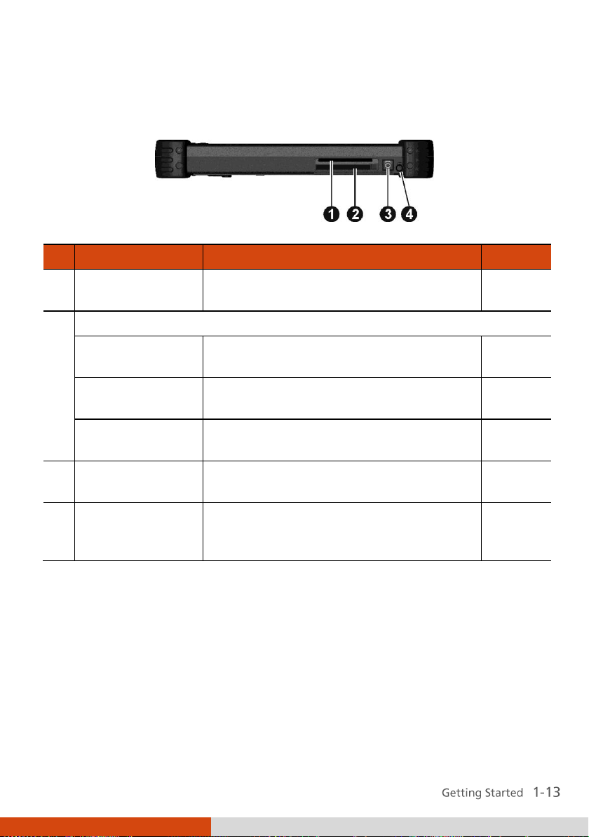
Top Components
Page 20

Ref
Component
Description
See Also
3G Pass-through
Connector
(optional)
Connects to the external antenna for
3G transmission.
NOTE: Must be connected via a docking
station.
GPS Pass-through
Connector
(optional)
Connects to the external antenna for
GPS receiver.
NOTE: Must be connected via a docking
station.
Docking Connector
Connects to the Docking Station
(available as an option).
P. 4-5
Power Connector
Connects the AC adapter.
P. 1-3
Bottom Components
Page 21

Chapter 2
Operating Your Tablet PC
This chapter provides information about the use of the Tablet PC.
If you are new to Tablet PCs, reading this chapter will help you learn the
operating basics. If you are already a computer user, you may choose to read
only the parts containing information unique to your Tablet PC.
Page 22

Using the Touchscreen
The screen of your Tablet PC is touch-sensitive. You can control the location
of the cursor/pointer on the screen using your finger or the included stylus
to communicate with the Tablet PC.
Page 23
Term
Action
Click/Point
Tap gently on the touchscreen.
Double-click
Tap twice on the touchscreen rapidly.
Drag and drop
Press lightly on the touchscreen and move your finger
until you reach your destination (drag). Finally, release
your finger (drop) when you finish dragging your
selection to the destination. The object will drop into the
new location.
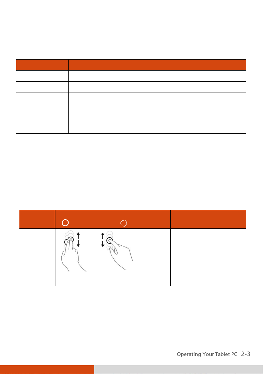
Gestures
Actions
( = finger down; = finger up)
Descriptions
Pan
(Scroll)
or
Drag 1 or 2 fingers up or down.
Use panning to see
another part of a page
that has scroll bars.
Here are some common terms that you should know when using the
touchscreen:
Using Multi-touch Gestures (Optional)
If your model comes with multi-touch-capable screen and Windows 7, you
can interact with your Tablet PC by placing two fingers on the screen. The
movement of the fingers across the screen creates “gestures,” which send
commands to the computer.
Here are the multi-touch gestures that you can use:
Page 24

Gestures
Actions
( = finger down; = finger up)
Descriptions
Zoom
(Pinch)
Move two fingers apart/toward each
other.
Use zooming to make
an item (a photo for
example) on the screen
larger or smaller. The
gesture works in
applications that
support mouse wheel
zooming.
Rotate
or
Move two fingers in opposing
directions.
-orUse one finger to pivot around
another.
Use rotating to move a
picture or other item
on the screen in a
circular direction
(clockwise or counterclockwise). The gesture
works in applications
that support the
specific gesture.
Press and
Tap
Press on target and tap using a
second finger.
Use press and tap to
access the shortcut
menu.
Page 25
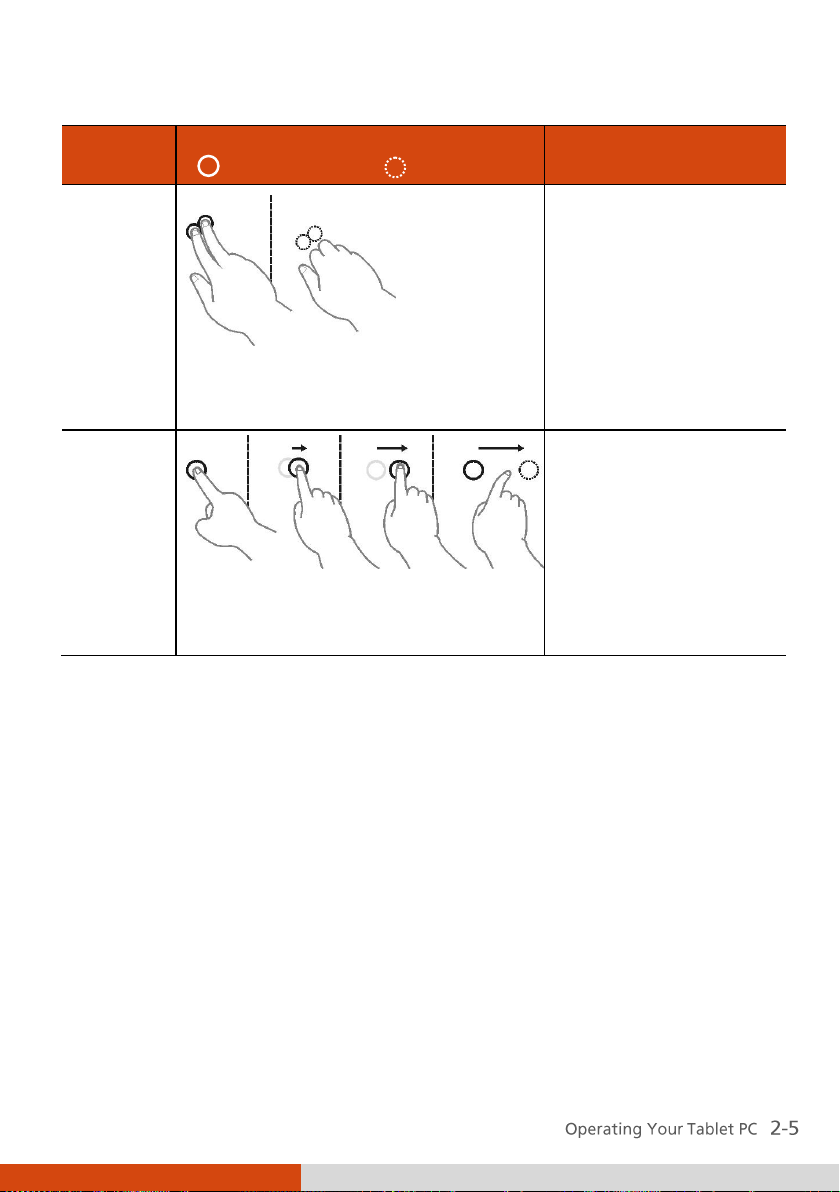
Gestures
Actions
( = finger down; = finger up)
Descriptions
Twofinger
Tap
Tap two fingers at the same time
(where the target is in the midpoint
between the fingers).
The function is defined
by applications that
support the specific
gesture.
Flicks
Make quick drag gestures in the
desired direction.
Flick left or right to
navigate back and
forward in a browser
and other
applications. The
gesture works in most
applications that
support back and
forward.
Page 26

Using the Input Panel
Use the Input Panel to enter text and perform various keyboard functions.
There are two types of Input Panels for you to use in Windows 7:
Touch Keyboard allows you to enter text by tapping the keys with your
stylus, like pressing the keys on a standard keyboard.
Writing Pad allows you to write on the writing pad, like writing on a
piece of paper. Your handwriting will be converted into typed text.
To open the Input Panel, tap the Input Panel tab, which appears by default
on the left edge of the screen. To switch between the two types, tap or
at the upper left corner of the Input Panel.
Page 27

Using the Keypad
The keypad of your Tablet PC can be divided into three areas:
Control buttons
Numeric, Delete (Del), and Enter (Ent) keys
Cursor-control keys
Control Buttons
Located on top of the keypad are three control buttons:
Fn button toggles the Fn keylock ON and OFF. When ON (indicated by
the icon on the taskbar), you can use the alternative functions of the
keypad keys (as described in the next two sections).
button toggles the keypad lock ON and OFF. Press the button to
lock the keypad (indicated by the icon on the taskbar) so that
accidental pressing of the keypad does not result in unexpected
operation. To unlock, press and hold the button for more than three
second.
Menu button toggles the OSD Control Panel ON and OFF. (See “Using
the OSD Control Panel” in Chapter 6 for detailed information.)
Page 28

Numeric Keypad with Alternative Functions
Shown below is the 12-key numeric keypad with Delete and Enter keys.
When the Fn keylock is ON (indicated by the icon on the taskbar), the
keys with orange icons provide alternative functions as described below.
rotates the screen display by 90 with each press.
switches the keypad backlight ON and OFF.
switches the sunlight-readable mode ON and OFF. When ON, the
display brightness is set to the highest level.
serves as the mouse right-click button.
C+A+D serves as the Ctrl+Alt+Del key combination for resetting the
system.
ESC serves as the Escape key.
Page 29

Cursor-Control Keys with Alternative Functions
Cursor-control keys control cursor movement. The word “cursor” refers to
the indicator on the screen (except for pointer on screen) that lets you know
exactly where on your screen anything you type will appear. It can take the
form of a vertical or horizontal line, a block, or one of many other shapes.
When the Fn keylock is ON (indicated by the icon on the taskbar), the
keys with orange icons provide alternative functions as described below.
increase the sound volume.
decrease the sound volume.
increase the brightness of LCD display.
decrease the brightness of LCD display.
Page 30

Using the Network Features
Using the LAN
The internal 10/100/1000Base-T LAN (Local Area Network) module allows
you to connect your Tablet PC to a network. It supports data transfer rate up
to 1000 Mbps.
To connect the network cable to the LAN module, connect one end of the
LAN cable to the RJ-45 connector ( ) on the Tablet PC and the other
end to the network hub.
Using the Wireless LAN (Optional)
The WLAN features include:
Peer-to-Peer (Ad-Hoc) and Access Point (Infrastructure) modes support
WEP (Wired Equivalent Privacy) 64/128-bit data encryption
IEEE 802.11a/g/n standard compliance
Page 31

Technology
802.11a
802.11g
802.11n
Stated Maximum
Throughput
(Mbps)
11
54
100 Mbps or more
Data Rates (Mbps)
11, 5.5, 2, 1
54, 36, 18, 9
100 ~ 210
Band (GHz)
2.412 ~ 2.462
2.4
2.4 / 5
Modulation
Technology
OFDM (Orthogonal
Frequency Division
Multiplexing)
OFDM (Orthogonal
Frequency Division
Multiplexing)
Spatial multiplexing,
uses MIMO (multipleinput multiple-output)
Turning On/Off the WLAN Radio
1. Press the Menu button on your Tablet PC to open the OSD Control Panel.
2. Click the RF button to switch the wireless radio on/off. The word ON or
OFF on the button indicates the current status.
3. Windows Mobility Center has wireless network turned on by default.
The Wireless Network icon on the taskbar should appear without a
Page 32

red X. (In case you have previously turned it off in Windows Mobility
Center, be sure to turn it on when using the function the next time.)
Connecting to a Wireless Network
1. Make sure that the WLAN function is enabled (as described above).
2. Tap the Wireless Network icon on the taskbar. (An orange light in the
icon indicates connections are available.)
3. In the list of available wireless networks, select a network, and then click
Connect.
4. Some networks require a network security key or passphrase. To connect
to one of those networks, ask your network administrator or Internet
service provider (ISP) for the security key or passphrase.
Page 33

Status
Icon
Off
(blue with red logo)
On
(blue with white logo).
Connected
(blue with green logo)
Using the Bluetooth Feature (Optional)
The Bluetooth technology allows short-range (about 10 meters) wireless
communications between devices without requiring a cable connection.
Data can be transmitted through walls, pockets and briefcases as long as two
devices are within range.
The status of the Bluetooth connection is indicated by the Bluetooth icon
located in the taskbar.
You can use the Bluetooth Utility to configure Bluetooth connection settings
and transfer files.
Turning On/Off the Bluetooth Radio
1. Press the Menu button on your Tablet PC to open the OSD Control Panel.
2. Click the RF button to switch the wireless radio on/off. The word ON or
OFF on the button indicates the current status.
Page 34

3. The Bluetooth function is enabled by default, as indicated by the
Bluetooth icon on the Windows taskbar. (In case you have previously
disabled the function in the Bluetooth utility, be sure to enable it when
using the function the next time.)
Connecting to another Bluetooth Device
1. Make sure that the Bluetooth function is enabled (as described above).
2. Make sure that the target Bluetooth device is turned on, discoverable
and within close range. (See the documentation that came with the
Bluetooth device.)
3. Start the Bluetooth utility by double-clicking the Bluetooth icon on
the taskbar and click New Connection.
Page 35

4. The Add New Connection Wizard window appears. Select Express Mode
(Recommended), and then click Next.
5. Select the device to connect to and click Next.
Page 36

6. Depending on the type of Bluetooth device that you want to connect to,
you will need to enter the pertinent information.
For detailed information on using the Bluetooth Utility, see the Bluetooth
Utility Help.
Page 37

Unlock
position
Using the 3G Feature (Optional)
3G is the third generation of mobile phone standards and technology after
2G. Services include wide-area wireless voice telephony and broadband
wireless data, all in a mobile environment.
Unlike IEEE 802.11 networks, 3G networks are “wide area cellular telephone
networks” which evolved to incorporate high-speed internet access and
video telephony. IEEE 802.11 networks are short range, high-bandwidth
networks primarily developed for data.
Installing the SIM Card
To use the 3G feature to connect to the Internet, you need to subscribe to
3G service and acquire a SIM card from the service provider. To install the
SIM card, follow these steps:
1. Make sure that the Tablet PC is not turned on or connected to AC power.
2. Lift the latch handle of the battery cover and turn it counterclockwise to
the unlock position. Then, detach the cover from the Tablet PC.
Page 38

3. Remove the two screws if existing (
battery pack off the Tablet PC ().
4. Locate the SIM card slot and push the SIM card into the slot. Make sure
the beveled corner on the SIM card is facing towards the Tablet PC and
that the golden contact area on the card is facing downwards.
). Pull on the ribbon strip to lift the
To remove the SIM card, just push in () the SIM card to pop-out () and
remove the card.
Page 39

5. Replace the battery pack.
6. Replace the battery cover and turn the latch clockwise to the lock
position.
Connecting to 3G Network
Turning On/Off the 3G Radio
1. Press the Menu button on your Tablet PC to open the OSD Control Panel.
2. Click the RF button to switch the wireless radio on/off. The word ON or
OFF on the button indicates the current status.
Page 40

3. Make sure that the 3G Utility (OneClick Internet) has 3G radio turned on.
Setting up a 3G Connection
To set up a 3G connection for the first time, follow these steps:
1. Make sure that the SIM card is inserted and the 3G function is enabled
(as described above).
2. Pull out the 3G antenna.
3. On Windows desktop, double click the OneClick Internet shortcut on
Windows desktop. The screen as below appears.
Page 41

4. If necessary, enter the PIN of your SIM card.
5. If the radio is currently off, click to turn on the radio.
6. Click Settings. You will be in the Profile page. Click to set up a new
profile.
7. Enter the required information. Contact your network operator for the
correct information.
Using the 3G Application
Once a new profile has been created, it will appear in the dropdown menu
Profiles. You can then select it by clicking Set Profile to use it.
You can manage the mobile Internet communication:
Internet Connection and Email download
SMS Manager
Page 42

Managing contacts from SIM and Outlook
GPS Management (for models having the GPS module)
Page 43

Using the Camera (Optional)
You can use G-Camera to perform the following:
Take pictures
Record video
Path tracking and capture (for models having the GPS module)
GPS information and settings (for models having the GPS module))
To start G-camera, double click the G-Camera shortcut icon on the Windows
desktop. The camera control panel appears.
Click the Shutter button
For detailed descriptions of G-Camera, click the button .
or press Enter to take photos.
Page 44

Using the Fingerprint Scanner (Optional)
The fingerprint scanner provides a strong authentication mechanism based
on fingerprint recognition. You can log on to your computer or sign in to a
web site with your fingerprint instead of a password. You can also encrypt
files and folders with your fingerprint.
To register your fingerprint, click Start All Programs Fingerprint
Software Fingerprint Registration. Click the finger you want to register
and follow the onscreen instructions to complete.
Page 45

You can then use the Fingerprint Software to set up how the fingerprint
authentication works.
For detailed information, click Start All Programs Fingerprint Software
Help.
Page 46

Page 47

Chapter 3
Managing Power
Your Tablet PC operates either on external AC power or on internal battery
power.
This chapter tells you how you can effectively manage power. To maintain
optimal battery performance, it is important that you use the battery in the
proper way.
Page 48

AC Adapter
The AC adapter serves as a converter from AC (Alternating Current) to DC
(Direct Current) power because your Tablet PC runs on DC power, but an
electrical outlet usually provides AC power. It also charges the battery pack
when connected to AC power.
The adapter operates on any voltage in the range of 100~240 V AC.
Page 49

Battery Pack
The battery pack is the internal power source for the Tablet PC. It is
rechargeable using the AC adapter.
The operating time of a fully charged battery pack depends on how you are
using the Tablet PC. When your applications often access peripherals, you
will experience a shorter operating time.
NOTE: Care and maintenance information for the battery is provided in the
“Battery Pack Guidelines” section in Chapter 7.
Charging the Battery Pack
NOTE:
z Charging will not start if the battery’s temperature is below 0 °C (32 °F)
or above 40 °C (104 °F); the charging process will stop if the battery’s
temperature gets above 60 °C (140 °F). To avoid damaging the battery
under this situation, disconnect the AC adapter and wait for the battery
to return to room temperature before charging again.
z During charging, do not disconnect the AC adapter before the battery
has been fully charged; otherwise you will get a prematurely charged
battery.
To charge the battery pack, connect the AC adapter to the Tablet PC and an
electrical outlet. The Battery Charge Indicator (
amber to indicate that charging is in progress. You are advised to keep the
Tablet PC power off while the battery is being charged. When the battery is
fully charged, the Battery Charge Indicator glows green.
) on the Tablet PC glows
It takes approximately 3 hours to fully charge the Li-Ion battery pack at a
room temperature of 25 °C (77 °F) (may need a longer charging time at
lower temperatures).
CAUTION: After the Tablet PC has been fully recharged, do not immediately
disconnect and reconnect the AC adapter to charge it again. Doing so may
damage the battery.
Managing Power 3-3
Page 50

Switch
Checking the Battery Level
By Operating System
You can check the approximate battery level using the battery meter
function of the operating system. To read the battery level in Windows, click
the battery icon on the taskbar.
By Gas Gauge
On the exterior side of the battery pack is a gas gauge for displaying the
estimated battery charge. When the battery pack is not installed in the
Tablet PC and you want to know the battery charge, you can press the
switch with a pointed device to see the corresponding value of indicator
segment that light green.
The value of the corresponding green segment indicates the relative
percentage of the battery charge. The battery pack is fully discharged when
you see no segment glowing green.
Page 51
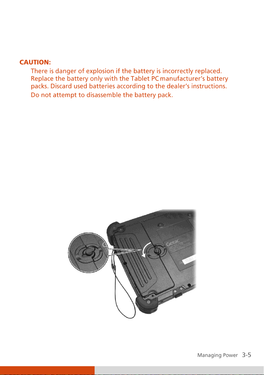
Unlock
position
Replacing the Battery Pack
If you often rely on battery power for a long period of time while traveling,
you may consider the purchase of an additional battery pack from your
dealer and keep it with you in a fully charged state as a backup.
To replace the battery pack, follow these steps:
1. Make sure that the Tablet PC is not turned on or connected to AC power.
(If your model comes with the backup battery option, you can keep the
power on when replacing the battery pack. The backup battery can
sustain power for up to 3 minutes, which should be long enough for you
to replace the battery pack.)
2. Lift the latch handle of the battery cover and turn it counterclockwise to
the unlock position. Then, detach the cover from the Tablet PC.
Page 52

3. Remove the two screws if existing (
battery pack off the computer ().
4. Fit another battery pack into place.
5. Replace the battery cover and turn the latch clockwise to the lock
position.
). Pull on the ribbon strip to lift the
Battery Low Signals and Actions
When the battery is low, Windows gives warning messages and the Battery
Charge Indicator ( ) blinks red to alert you.
Immediately save your data upon Battery Low. The remaining operating time
depends on how you are using the Tablet PC.
Always respond to Battery Low by placing your Tablet PC on the Sleep or
Hibernation mode, turning off the Tablet PC, or connecting the AC adapter.
If you do not take any action, the Tablet PC will automatically hibernate and
turn off.
Page 53

What...
When...
Power to the hard disk is turned
off
When the hard disk has been idle for a
set period.
Power to the display is turned off
When the display has been idle for a
set period.
The Tablet PC enters the Sleep
mode. The hard disk and display
are turned off and the entire
system consumes less power.
When the entire system has been idle
for a set period.
When you manually activate the mode.
The Tablet PC enters the
Hibernation mode. (See the next
subsection for more information.)
When the entire system has been idle
for a set period.
When you manually activate the mode.
Power Management
Your Tablet PC supports ACPI (Advanced Configuration and Power Interface)
for power management. The power management feature allows you to
reduce the power consumption for energy saving.
With an ACPI-compliant operating system such as Windows, power supply to
different Tablet PC components is controlled on an as-needed basis. This
allows maximum power conservation and performance at the same time.
In general, Windows’ power management works in this way:
For detailed information on power management, see Windows’ Help.
Page 54

Hibernation
Hibernation is a very useful feature. People frequently open many
applications when they use computers. It takes some time to get all these
applications open and running, and normally they all have to be closed
before the computer can be turned off.
When you use the hibernation feature, you do not have to close the
applications. The Tablet PC stores the state of your Tablet PC to a file on the
hard disk and then shuts down. The next time you turn on your Tablet PC,
you return to exactly where you left off.
Page 55

Power-Saving Tips
Aside from enabling your Tablet PC’s power saving mode (see previous
section), you can do your part to maximize the battery’s operating time by
following these suggestions.
Do not disable Power Management.
Decrease the LCD brightness to the lowest comfortable level.
Shorten the length of time before Windows turn off the display.
Many USB devices use power just by being connected. If you use a USB
mouse, you can save power by disconnecting the mouse and using the
optional stylus. If you use a USB flash drive, unplug it when you are not
using it.
Remove the card (such as PC card and Smart Card) if not using it.
Turn off the wireless radio if you are not using the wireless module (such
as WLAN, Bluetooth, or 3G).
Turn off the Tablet PC when you are not using it.
Page 56

Page 57

Chapter 4
Expanding Your Tablet PC
You can expand the capabilities of your Tablet PC by connecting other
peripheral devices. When using a device, be sure to read the instructions
accompanying the device together with the relevant section in this chapter.
Page 58

Using Smart Cards
Depending on your model, your Tablet PC has one or two smart card
readers.
With an embedded microcontroller, smart cards have the unique ability to
store large amounts of data, carry out their own on-card functions (e.g.,
encryption and mutual authentication), and interact intelligently with a
smart card reader.
To insert a smart card:
1. Locate the smart card reader.
2. Slide the smart card, with its label and embedded computer chip facing
up into the slot.
To remove a smart card:
1. Make sure that the software is not accessing the smart card.
2. Pull the card out of the slot.
Page 59

Eject button
Using PC Cards
The PC card slot supports type II card and CardBus specifications.
To insert a PC card:
1. Locate the PC card slot (the one with the eject button).
2. Slide the PC card, with its label facing up, into the slot until the eject
button pops out.
3. When a new card is seated, the Tablet PC will detect it and try to install
To remove a PC card:
1. Double-click on the Safely Remove Hardware icon found on the
2. Select (highlight) the PC card from the list to disable the card.
3. Push the eject button and the card will slide out slightly.
4. Pull the card out of the slot.
the appropriate driver. Follow the on-screen instructions to complete the
process.
Windows taskbar and the Safely Remove Hardware window appears on
screen.
Page 60

Connecting a USB Device
Your Tablet PC has two USB ports for connecting USB devices, such as a
digital camera, scanner, printer, modem, and mouse.
The USB ports support transfer rates up to 12 MB/s for USB 1.1 devices and
480 MB/s for USB 2.0 devices.
To connect a USB device, simply plug the device cable to one of the USB
ports ( ).
Page 61

Connecting a Serial Device
Your computer has a serial port for connecting a serial device such as a serial
mouse or serial communication device.
Follow this procedure to connect a serial device:
1. Make sure the computer is not turned on.
2. Plug the device cable to the serial port.
3. Turn on the computer.
Page 62

Connecting an Audio Device
For higher audio quality, you can send sound through external audio devices
such as speakers, headphones, or earphone set using the headphone out
connector.
Page 63

Using the Docking Station
Docking Station is available as an option. The device eliminates the hassles
of having you connect and disconnect the various cables when carrying your
Tablet PC around and allows a variety of peripherals to be connected.
1. Locate the docking connector.
2. Connect the Docking Station to the docking connector.
For more detailed information, refer to the operating Instructions of the
Docking Station.
Menu Docking
Page 64

Page 65

Chapter 5
Using BIOS Setup and System Recovery
BIOS Setup Utility is a program for configuring the BIOS (Basic Input/ Output
System) settings of the Tablet PC. BIOS is a layer of software, called
firmware, that translates instructions from other layers of software into
instructions that the Tablet PC hardware can understand. The BIOS settings
are needed by your Tablet PC to identify the types of installed devices and
establish special features.
System Recovery reinstalls Windows to your system and configures it to the
system’s factory default settings.
This chapter tells you how to use the BIOS Setup and System Recovery.
Page 66

Information
Main
Advanced
Security
Boot
Exit
Model NO:
Serial NO:
Processor Info:
Installed System Memory:
SATA Port 1
BIOS Revision:
EC Revision:
LAN MAC Address:
Operating Time:
E100-A
0123456789
Intel(R) Atom(TM) CPU N450 @1.66GHz
2048MB
[INTEL SSDSA1M080G2GN] 80GB
R0.51.070520F
R0.51b
00-E0-4C-68-00-0C
57 Hours
F1 Help ↑↓ Select Item -/+ Change Values F9 Setup Defaults
Esc Exit ←→ Select Menu Enter Select Sub-Menu F10 Save and Exit
BIOS Setup
When and How to Use
You need to run BIOS Setup Utility when:
You see an error message on the screen requesting you to run BIOS
Setup Utility.
You want to restore the factory default BIOS settings.
You want to modify some specific settings according to the hardware.
You want to modify some specific settings to optimize the system
performance.
To run BIOS Setup utility, press the Ent key when the prompt appears on the
screen during system startup. The prompt shows up on the screen for only a
few seconds. You must press the Ent key quickly. A small window appears,
press Ent again to perform the first option (Launch System Setup). The BIOS
Setup Utility main screen appears as shown next.
Page 67

Information
Main
Advanced
Security
Boot
Exit
Model NO:
Serial NO:
Processor Info:
Installed System Memory:
SATA Port 1
BIOS Revision:
EC Revision:
LAN MAC Address:
Operating Time:
E100-A
0123456789
Intel(R) Atom(TM) CPU N450 @1.66GHz
2048MB
[INTEL SSDSA1M080G2GN] 80GB
R0.51.070520F
R0.51b
00-E0-4C-68-00-0C
57 Hours
F1 Help ↑↓ Select Item -/+ Change Values F9 Setup Defaults
Esc Exit ←→ Select Menu Enter Select Sub-Menu F10 Save and Exit
In general, you can use the arrow keys to move around and + / – keys to
change the setup values. Keyboard information can be found at the bottom
of the screen. The keypad of your Tablet PC does not provide all the keys for
operating the utility. You will need to connect a USB keyboard before
running BIOS Setup. (To use the USB keyboard, make sure that the item
“Legacy USB Support” under the Main menu is set to
Enabled
.)
Information Menu
The Information menu contains the basic configuration information of the
system. There are no user-definable items in this menu.
Page 68

Information
Main
Advanced
Security
Boot
Exit
System Time:
System Date:
Legacy USB Support:
SATA Controller Mode Option:
SATA AHCI Enable
[ :33:08]
[05/14/2010]
[Enabled]
[Enhanced]
[Enabled]
Item Specific Help
<Tab>, <Shift-Tab>, or
<Enter> selects field.
F1 Help ↑↓ Select Item -/+ Change Values F9 Setup Defaults
Esc Exit ←→ Select Menu Enter Select Sub-Menu F10 Save and Exit
11
Main Menu
The Main menu contains the various system settings.
System Time sets the system time.
System Date sets the system date.
Legacy USB Support enables or disables the system’s support for Legacy USB
device in DOS mode.
SATA Controller Mode Option sets to
to
Compatible
for Legacy mode. SATA/PATA drives will be auto-detected
Enhanced
for Native IDE mode or sets
and SATA drives will be placed in the mode specified.
SATA AHCI Enable sets if SATA AHCI is enabled. (This item appears only if
the previous item is set to
Enhanced
.)
Page 69

Information
Main
Advanced
Security
Boot
Exit
IGD – Memory Size:
DVMT Graphics Memory:
Power Button Delay:
AC Initiation:
Emergency Button:
Emergency Button Delay:
High temperature Protection:
LAN DSM (Deep Slumber Mode):
Smart Card Power management:
Charging Backup battery:
RTC wakeup from S4 mode(with AC-in):
[ ]
120MB
[Disabled]
[Disabled]
[Enabled]
[Disabled]
[Enabled]
[Enabled]
[Disabled]
[Disabled]
[Disabled]
Item Specific Help
Select the amount of
Main Memory that the
Internal Graphics
Device will use.
F1 Help ↑↓ Select Item -/+ Change Values F9 Setup Defaults
Esc Exit ←→ Select Menu Enter Select Sub-Menu F10 Save and Exit
128MB
Advanced Menu
The Advanced menu contains the advanced settings.
IGD – Memory Size sets the amount of total graphics memory (pre-allocated
+ fixed + DVMT) for use by the internal graphics device.
DVMT Graphics Memory shows the size of DVMT graphics memory.
Power Button Delay sets the amount of time (2, 4, 6, or 8 seconds) to press
and hold the power button for it to function.
AC Initiation sets if connecting AC power will automatically start or resume
your Tablet PC.
Emergency Button enables or disables the emergency button (5 on the
numeric keypad). This is only for customized applications that support the
button.
Emergency Button Delay sets the amount of time to press and hold the
emergency button for it to function.
Page 70

HDD Preheat keeps the hard disk drive’s temperature above 3oC (37oF)
during system shutdown period. When set to
will automatically turn on whenever the hard disk drive’s temperature drops
below 3oC (37oF). (The availability of this item depends on your model.)
High Temperature Protection enables or disables the hard disk protection
against high temperatures. When set to
appear on the screen when the hard disk temperature goes above the safe
range. You will not be able to use the system before the hard disk cools
down and the message disappears.
LAN DSM enables or disables the Deep Slumber Mode feature of the LAN
module. When set to
when the LAN cable is connected.
SmartCard power management allows you to save power for the Smart
Card reader. When set to
when a Smart Card is inserted. When set to
the time.
Charging Backup Battery allows the main battery to charge the backup
battery (option). When set to
by the main battery when the AC adapter is not connected and the main
battery has more than 70% capacity left. When set to
battery will be charged by the AC adapter only. (The availability of this item
depends on your model.)
Enabled
Auto
, power is supplied to the LAN module only
, power is supplied only to the reader only
Enabled
, the backup battery will be charged
Enabled
Enabled
Enabled
, the optional heater
, a warning message will
, power is supplied all
Disabled
, the backup
RTC wake up from S4 mode (with AC-in) enables or disables the RTC (Real
Time Clock) wakeup from S4 (Hibernation) feature when AC power is
connected. Set this item to
have the computer automatically perform tasks at specific times.
Enabled
if you use Windows task scheduler to
Page 71

Information
Main
Advanced
Security
Boot
Exit
Supervisor Password Is:
Set Supervisor Password
Current TPM State:
Change TPM State
Clear
[Enter]
Disabled & Deactivated
[No Change ]
Item Specific Help
Supervisor Password
controls access to the
Setup utility.
F1 Help ↑↓ Select Item -/+ Change Values F9 Setup Defaults
Esc Exit ←→ Select Menu Enter Select Sub-Menu F10 Save and Exit
Enter
Security Menu
The Security menu contains the security settings, which safeguard your
system against unauthorized use.
Supervisor Password Is shows whether you have set the supervisor
password or not for the system.
Set Supervisor Password sets the supervisor password. When typing the
password, first make sure that Num Lock is off, and then type the password
in the entry fields and press Enter. Confirm your password by typing it again
and pressing Enter. When set, the supervisor password is required for
entering BIOS Setup.
Current TPM State shows the current TPM state. TPM (Trusted Platform
Module) is a component on your computer’s mainboard that is specifically
designed to enhance platform security by providing a protected space for
key operations and other security critical tasks.
Change TPM State allows you to select among
Activate, Deactivate & Disable
, and
Clear
.
No Change, Enable &
Page 72

Information
Main
Advanced
Security
Boot
Exit
Boot priority order:
1: USB KEY:
2: SATA HDD: INTEL SSDSA1M080G2GN-(S1)
3: SATA HDD:
4: USB FDC:
5: USB CDROM:
6: USB HDD:
7: PCI BEV: Realtek Boot Agent
8:
Excluded from boot order:
: Other USB:
: PCI:
Item Specific Help
Keys used to view or
configure devices:
Up and Down arrows select
a device.
<+> and <-> moves the
device up or down.
<x> exclude or include
the device to boot.
<Shift + 1> enables or
disables a device.
<1 – 4> Loads default
boot sequence.
F1 Help ↑↓ Select Item -/+ Change Values F9 Setup Defaults
Esc Exit ←→ Select Menu Enter Select Sub-Menu F10 Save and Exit
Boot Menu
The Boot menu sets the sequence of the devices to be searched for the
operating system.
The bootable devices will be automatically detected during POST and shown
here, allowing you to set the sequence that the BIOS uses to look for a device
from which to load the OS. See the information on the right side of the
menu for keyboard usage.
Page 73
Information
Main
Advanced
Security
Boot
Exit
Exit Saving Changes
Exit Discarding Changes
Load Setup Defaults
Discard Changes
Save Changes
Item Specific Help
Exit System Setup and
save your changes to
CMOS.
F1 Help ↑↓ Select Item -/+ Change Values F9 Setup Defaults
Esc Exit ←→ Select Menu Enter Select Sub-Menu F10 Save and Exit
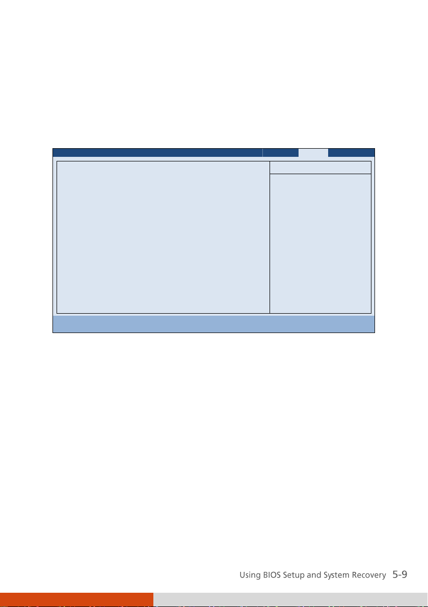
Exit Menu
The Exit menu displays ways of exiting BIOS Setup Utility. After finishing
with your settings, you must save and exit so that the changes can take
effect.
Exit Saving Changes saves the changes you have made and exits BIOS Setup
Utility.
Exit Discarding Changes exits BIOS Setup Utility without saving the changes
you have made.
Load Setup Defaults loads the factory default values for all the items.
Discard Changes restores the previous values for all the items.
Saves Changes saves the changes you have made.
Page 74

System Recovery
Use System Recovery when:
The Windows operating system does not start at all.
You want to restore the system to the factory state.
To run System Recovery:
1. It is recommended that you connect the AC adapter to ensure power
supply throughout the process.
2. During system startup when the following screen appears, press Ctrl +
Alt + F2 keys for four seconds or press Ent and select HDI Recovery when
a small window appears on the screen.
Page 75

3. A message appears asking if you want to continue. Type 1 to continue.
4. A warning message appears asking if you accept the terms as shown on
the screen. Type 1 to continue.
5. Type 1 again when the next message appears asking for confirmation.
6. The recovery process starts. The screen as below appears.
7. Wait till the process completes. A message will appear asking you to
press any key to continue. Press any key for the system to restart.
8. The Windows setup wizard starts. Follow the onscreen prompts to
continue.
9. When the system restarts, the installer screen as below appears. The
installer will perform system hardware detection and driver installation.
Page 76

10. When completed, the system restarts and displays Windows desktop.
Page 77

Chapter 6
Using Special Utilities
Special utilities are provided for enhanced capabilities and management.
This chapter describes how to use these utilities.
Page 78

Using the OSD Control Panel
The OSD (On Screen Display) Control Panel provides a user-friendly interface
for you to quickly activate or operate certain functions on your Tablet PC
with a simple tap of the screen.
To open the OSD Control Panel, press the Menu button on your Tablet PC.
The following screen appears.
Page 79

Icon
Function
/
Shows the current ON/OFF status of keypad lock.
/
Shows the current ON/OFF status of Fn keylock.
Opens the Help file explaining the OSD Control Panel.
Opens the Quick Button Setup menu (refer to the next
section for details).
Closes the OSD Control Panel.
Serves as the master ON/OFF control of the RF radio. The
word on the button indicates the current status.
When set to OFF, all wireless modules (WLAN/Bluetooth/3G)
cannot be used. When set to ON, individual settings of
the module work.
The on/off status will persist through Sleep/Hibernation
mode but it will always be on upon restarting.
Switches the ECO mode to the next choice (MAX, QUICK,
WORK, or OFF). The word on the button indicates the
current status. (For information on ECO modes, see “ECO
Tab” later in this chapter.)
This button works only when using battery power. The
ECO mode will return to the default OFF setting
whenever AC power is connected, backlight status is
changed by using the button , the computer
resumes from Sleep/Hibernation mode, or the computer is
restarted.
The status would display IN when you connect your Tablet
PC to the Docking Station.
To turn off power to the Docking Station without
disconnecting from your Tablet PC, click the Docking
button. Before removing your Tablet PC from the
Docking Station, make sure to click the Docking button to
show OUT.
The following table shows the various functions on the OSD Control Panel.
Page 80

Icon
Function
Switches the LCD backlight to the next choice (MAX,
AUTO, or MANUAL.) The word on the button indicates
the current status.
When set to MAX, the backlight is adjusted to the
highest brightness level. When set to AUTO, the
brightness will be automatically adjusted according to
the current ambient light.
The backlight will return to the default MANUAL setting
whenever the computer resumes from Sleep/Hibernation
mode or the computer is restarted.
Rotates the orientation from default landscape to 90o
portrait, 180o landscape, or 270o portrait.
The status will persist through Sleep/Hibernation mode
or system power off.
Switches the display output to the next choice: VGA
(external monitor), BOTH (LCD and external monitor), or
LCD.
This button works only when an external display is
connected.
Starts Microsoft Internet Explorer by default.
You can assign a different function to this button (refer
to the next section for details).
Starts Windows Mobility Center by default.
You can assign a different function to this button (refer
to the next section for details).
Starts the touchscreen calibration tool by default.
You can assign a different function to this button (refer
to the next section for details).
Starts the Bluetooth Setup utility by default.
You can assign a different function to this button (refer
to the next section for details).
Page 81

Icon
Function
Opens the Input Panel by default.
You can assign a different function to this button (refer
to the next section for details).
Allows you to adjust the sound volume by dragging the
knob along the bar.
Switches the system sound output OFF (mute) and ON.
Allows you to adjust the LCD brightness level by dragging
the knob along the bar.
System enters “black-out” mode by turning off the LCD
display, LED indicators, touchscreen, and sound.
Press the power button ( ) to wake up the system from
“black-out” mode.
Page 82
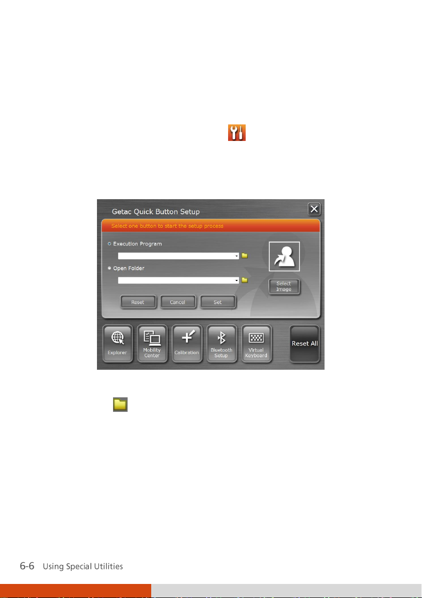
Quick Button Setup
By default, the five quick buttons on the OSD Control Panel have
pre-assigned functions. You can re-define the buttons:
1. Click the Quick Button Setup button ( ) on the OSD control panel
and the Quick Button Setup window appears.
2. At the bottom of the screen are the five quick buttons. Click the button
you want to change.
3. Depending on the type of task to be associated with the button, click the
Open button of the Executed Program or Open Folder type.
4. A dialog box appears. Select the desired program or folder and click
Open or Select. After your selection, the entry field will display the
program or folder information.
Page 83

or
5. You can change the image appearing on the button by clicking the
Select Image button. After selecting the image file, the original image
on the button will be replaced.
6. Click Set to complete the changes.
Page 84

Using G-Manager
G-Manager is a unified user interface utility that allows you to manage and
configure the following:
System
Battery
ECO (economic mode)
Light Sensor
Ignition
Monitoring
Antenna
GPS Status
Starting G-Manager
You can start up G-Manager by any of the following methods:
Click Start All Programs Getac Utility G-Manager, or
Click and hold the icon located on the taskbar until a ring appears.
From the small menu that pops up, click G-Manager.
The G-Manager window appears, containing 8 tabs as described later.
Page 85

System Tab
The System tab provides system information.
To view specific information, select the component from the list on the left
side of the screen. The information of the selected component will be
displayed on the right side of the screen.
Page 86

Battery Tab
The Battery tab allows you to check the battery status and configure the
battery.
At most two batteries may be supported. Click Battery 1 or Battery 2 to view
the information of each battery (if your model has a second battery).
% Left
Battery Status
Battery Information
The upper portion of the screen displays the current status of the selected
battery.
Page 87

Charging Mode
The lower left portion of the screen allows you to select the charging mode.
Normal Mode – The battery will be fully charged. When remaining
charge reaches below 95%, then charging will start until it is fully
charged.
Economy Mode – This mode helps prolong battery life by charging up to
80% of its total capacity only. It is highly recommended if you are using
AC power most of the time.
Gauge Reset
The lower right portion of the screen contains the battery health bar and
provides the battery calibration function.
The health bar shows the batter’s health by percentage. A low percentage
indicates poor health and therefore the need to perform a gauge reset to
calibrate the battery’s capacity and improve the battery’s performance. The
gauge reset process includes discharging and then fully recharging the
battery in two cycles. It can take several hours.
To perform a gauge reset:
1. Connect the AC adapter.
2. Click Start, located next to the health bar
3. In the pop-up dialog box, click Yes to start the process. The window as
below appears displaying the progress bar.
Page 88

4. Wait till the process is completed. Click Exit when finished.
ECO Tab
The ECO tab allows you to configure ECO modes (or called power profiles).
To put the system into an ECO mode, use the ECO button (one of the
buttons in the OSD Control Panel). (See “Using the OSD Control Panel”
earlier in this chapter for information.)
Page 89

ECO Information
The left portion of the screen lists the available power profiles (Quick, Power
Saving, and Work). Each profile is a combination of power settings that
results in different power consumptions. To change the settings of a profile,
select (highlight) the profile name in the list.
Profile Settings
The right portion of the screen displays the settings of the current selected
profile. You can set up the following items:
WWAN (3G), Bluetooth, and WLAN – can be on or off.
Power Scheme – can be Balanced, High Performance or Power Saver.
The settings here correspond to the settings in Windows. (See Windows
Help for the description to each of the power scheme.)
After changing the settings, click Apply or OK to save the changes. To
restore the settings to the default values, click Default.
Page 90

Light Sensor Tab
The Light Sensor tab allows you configure how the light sensor works.
Sensor Mode
The left portion of the screen lists the sensor modes:
Normal – Light sensor sensitivity is set at normal environment lighting
condition.
Bright – Light sensor sensitivity is set at bright environment lighting
condition (e.g. outdoors).
Dark – Light sensor sensitivity is set at dark environment lighting
condition (e.g. indoors, storage warehouse, etc.).
Click to select a mode. Click Apply or OK to save the changes.
Page 91

Environment Illuminance
To have the keypad backlight automatically turn on in poor lighting
environment, click the checkbox Automatic Keyboard Backlit. Click Apply or
OK to save the changes.
Antenna Tab
The Antenna tab allows you to set if your system will automatically use the
external GPS or 3G antenna when connected to the Docking Station.
Select the checkbox(es) accordingly. Click Apply or OK to save the changes.
Page 92

Ignition Tab
The Ignition tab allows you to configure how your system works with the
vehicle ignition.
Ignition Control
When your system is connected to the Vehicle Dock (available as an option),
you can have your system derive power from the vehicle and have the on/off
of the vehicle ignition turn on/off your system. To enable the feature, select
the checkbox Ignition Power On. Click Apply or OK to save the changes.
Delay Time
When the Ignition Power On feature is enabled, the system will
automatically shut down after the vehicle ignition is turned off or the
battery is low. You can set the amount of time (20 seconds, 30 seconds, 45
seconds, 1 minute, or 2 minute) the system waits before shutting down. Click
Apply or OK to save the changes.
Page 93

Monitoring Tab
The Monitoring tab allows you to configure the monitoring function of
G-Manager.
Items to Monitor
The left portion of the screen lists the items. Click the checkbox before an
item to include it as a monitored component. Click Apply or OK to save the
changes.
Monitoring Options
The right portion of the screen allows you to set how the monitored items
are displayed and how often the monitoring is updated.
Always On Top – allows the monitoring window to remain on top of
your display.
Page 94

Monitoring Interval – sets the frequency of updates on the monitoring
window (1/3/5/10/30 seconds or 1/5/30 minutes).
Click Apply or OK to save the changes.
Starting and Stopping the Monitoring
To start monitoring, click START Monitor. The monitoring window similar to
the one below appears displaying requested information at specified
intervals.
To stop monitoring, click the Close button at the upper right corner of the
monitoring window or click Stop Monitor on the Monitoring tab page of
G-Manager.
Page 95

GPS Status Tab
The GPS Status tab shows the GPS status for models having the GPS module.
To start GPS positioning, click Start GPS. The screen displays:
Ongoing raw data strings in the Message Log section
Overhead satellite positions in the Satellite Map section
Signal strength of the satellites in the Signal Indicator section
When GPS positioning is completed, the Data Summary section shows the
GPS information of the current location.
To stop GPS positioning, click Stop GPS.
Page 96

Page 97

Chapter 7
Caring for the Tablet PC
Taking good care of your Tablet PC will ensure a trouble-free operation and
reduce the risk of damage to your Tablet PC.
This chapter gives you guidelines covering areas such as protecting, storing,
cleaning, and traveling.
Page 98

Protecting the Tablet PC
To safeguard the integrity of your Tablet PC data as well as the Tablet PC
itself, you can protect the Tablet PC in several ways as described in this
section.
Using the Cable Lock
You can use a Kensington-type cable lock to protect your Tablet PC against
theft. The cable lock is available in computer stores.
To use the lock, loop the lock cable around a stationary object such as a
table. Insert the lock to the Kensington lock hole and turn the key to secure
the lock. Store the key in a safe place.
Page 99

Using an Anti-Virus Strategy
You can install a virus-detecting program to monitor potential viruses that
could damage your files.
Using Action Center (for Windows 7)
Action Center alerts you to take action on the following security essentials:
Windows Firewall
Windows Update
Malware Protection (anti-virus, anti-spyware)
Others (Internet security, user account control)
For detailed information, see Windows’ online Help.
Page 100

Taking Care of the Tablet PC
Location Guidelines
For optimal performance, use the Tablet PC where the recommended
temperature is between 10 C (50 F) and 35 C (95 F) – actual operating
temperature depending on product specifications.
Avoid placing the Tablet PC in a location subject to high humidity,
extreme temperatures, mechanical vibration, direct sunlight, or heavy
dust.
Do not cover or block any ventilation openings on the Tablet PC. For
example, do not place the Tablet PC on a bed, sofa, rug, or other similar
surface. Otherwise, overheating may occur that results in damage to the
Tablet PC.
Keep the Tablet PC at least 13 cm (5 inches) away from electrical
appliances that can generate a strong magnetic field such as a TV,
refrigerator, motor, or a large audio speaker.
Avoid moving the Tablet PC abruptly from a cold to a warm place. A
temperature difference of more than 10 C (18 F) may cause
condensation inside the unit, which may damage the storage media.
Do not place the Tablet PC on an unsteady surface.
General Guidelines
Do not place heavy objects on top of the Tablet PC as this may damage
the display.
The screen surface is easily scratched. Do not use paper towels to clean
the display but use the included soft cloth. Avoid touching it with your
fingers, pen, or pencil.
To maximize the life of the backlight in the display, allow the backlight
to automatically turn off as a result of power management. Avoid using
 Loading...