

Page 1

GE
Measurement & Control Solutions Flow
C-PT Ultrasonic Flow Transducer
Installation Guide
916-074 Rev. B
July 2010
Page 2

Page 3

C-PT Ultrasonic Flow Transducer
Installation Guide
916-074 Rev. B
July 2010
GESensingInspection.com
©2010 General Electric Company. All rights reserved.
Technical content subject to change without notice.
Page 4

[no content intended for this page]
ii
Page 5

Contents
1. Introduction. . . . . . . . . . . . . . . . . . . . . . . . . . . . . . . . . . . . . . . . . . . . . . . . . . . . . . . . . . . . . . . . . . . . . . . . . . . . . . . . . . . . . . . . . . . .1
2. Transducer Construction. . . . . . . . . . . . . . . . . . . . . . . . . . . . . . . . . . . . . . . . . . . . . . . . . . . . . . . . . . . . . . . . . . . . . . . . . . . . . . . . 1
3. Measurement Methods . . . . . . . . . . . . . . . . . . . . . . . . . . . . . . . . . . . . . . . . . . . . . . . . . . . . . . . . . . . . . . . . . . . . . . . . . . . . . . . . . 2
3.1 Transit-Time Method. . . . . . . . . . . . . . . . . . . . . . . . . . . . . . . . . . . . . . . . . . . . . . . . . . . . . . . . . . . . . . . . . . . . . . . . . . . . . . . . 2
3.2 TransFlection Method . . . . . . . . . . . . . . . . . . . . . . . . . . . . . . . . . . . . . . . . . . . . . . . . . . . . . . . . . . . . . . . . . . . . . . . . . . . . . . . 2
4. Couplants . . . . . . . . . . . . . . . . . . . . . . . . . . . . . . . . . . . . . . . . . . . . . . . . . . . . . . . . . . . . . . . . . . . . . . . . . . . . . . . . . . . . . . . . . . . . . .3
5. Installing C-PT Transducers for the Transit-time Method. . . . . . . . . . . . . . . . . . . . . . . . . . . . . . . . . . . . . . . . . . . . . . . . . .4
5.1 Determining the Number of Traverses . . . . . . . . . . . . . . . . . . . . . . . . . . . . . . . . . . . . . . . . . . . . . . . . . . . . . . . . . . . . . . .4
5.2 Installing the Universal Clamping Fixture - UCF . . . . . . . . . . . . . . . . . . . . . . . . . . . . . . . . . . . . . . . . . . . . . . . . . . . . . . .6
5.2a Verifying Fixture Length. . . . . . . . . . . . . . . . . . . . . . . . . . . . . . . . . . . . . . . . . . . . . . . . . . . . . . . . . . . . . . . . . . . . . . .6
5.2b Identifying the UCF Components . . . . . . . . . . . . . . . . . . . . . . . . . . . . . . . . . . . . . . . . . . . . . . . . . . . . . . . . . . . . . . 6
5.2c The Double-Traverse Method -UCF . . . . . . . . . . . . . . . . . . . . . . . . . . . . . . . . . . . . . . . . . . . . . . . . . . . . . . . . . . . .8
5.2d The Single-Traverse Method - UCF . . . . . . . . . . . . . . . . . . . . . . . . . . . . . . . . . . . . . . . . . . . . . . . . . . . . . . . . . . .11
5.2e Mounting Transducers into the UCF . . . . . . . . . . . . . . . . . . . . . . . . . . . . . . . . . . . . . . . . . . . . . . . . . . . . . . . . . .16
5.3 Installing the General Clamping Fixture - GCF . . . . . . . . . . . . . . . . . . . . . . . . . . . . . . . . . . . . . . . . . . . . . . . . . . . . . . .19
5.3a The Double-Traverse Method - GCF . . . . . . . . . . . . . . . . . . . . . . . . . . . . . . . . . . . . . . . . . . . . . . . . . . . . . . . . . .19
5.3b The Single-Traverse Method - GCF . . . . . . . . . . . . . . . . . . . . . . . . . . . . . . . . . . . . . . . . . . . . . . . . . . . . . . . . . . .23
5.3c Mounting Transducers into the GCF . . . . . . . . . . . . . . . . . . . . . . . . . . . . . . . . . . . . . . . . . . . . . . . . . . . . . . . . . .27
5.4 Installing the Magnetic Clamping Fixture - MCF. . . . . . . . . . . . . . . . . . . . . . . . . . . . . . . . . . . . . . . . . . . . . . . . . . . . . .30
5.4a Identifying the MCF Components. . . . . . . . . . . . . . . . . . . . . . . . . . . . . . . . . . . . . . . . . . . . . . . . . . . . . . . . . . . . .30
5.4b The Double-Traverse Method - MCF . . . . . . . . . . . . . . . . . . . . . . . . . . . . . . . . . . . . . . . . . . . . . . . . . . . . . . . . . .31
5.4c The Single-Traverse Method - MCF . . . . . . . . . . . . . . . . . . . . . . . . . . . . . . . . . . . . . . . . . . . . . . . . . . . . . . . . . . .33
5.4d Mounting Transducers into the MCF . . . . . . . . . . . . . . . . . . . . . . . . . . . . . . . . . . . . . . . . . . . . . . . . . . . . . . . . . .37
6. Installing C-PT Transducers for the TransFlection Method . . . . . . . . . . . . . . . . . . . . . . . . . . . . . . . . . . . . . . . . . . . . . . .40
6.1 Mounting the TransFlection Mode Clamping Fixture - TMCF . . . . . . . . . . . . . . . . . . . . . . . . . . . . . . . . . . . . . . . . . .40
6.1a Mounting the TMCF in a <180o Configuration . . . . . . . . . . . . . . . . . . . . . . . . . . . . . . . . . . . . . . . . . . . . . . . . .41
6.1b Mounting the TMCF in a 180o Configuration . . . . . . . . . . . . . . . . . . . . . . . . . . . . . . . . . . . . . . . . . . . . . . . . . .44
6.2 Mounting the Transducers into the TransFlection Mode Clamping Fixture - TMCF. . . . . . . . . . . . . . . . . . . . . .47
7. Maintaining the C-PT Transducers. . . . . . . . . . . . . . . . . . . . . . . . . . . . . . . . . . . . . . . . . . . . . . . . . . . . . . . . . . . . . . . . . . . . . .50
8. Specifications . . . . . . . . . . . . . . . . . . . . . . . . . . . . . . . . . . . . . . . . . . . . . . . . . . . . . . . . . . . . . . . . . . . . . . . . . . . . . . . . . . . . . . . . .51
8.1 General Specifications . . . . . . . . . . . . . . . . . . . . . . . . . . . . . . . . . . . . . . . . . . . . . . . . . . . . . . . . . . . . . . . . . . . . . . . . . . . . .51
8.2 Hazardous Area Certifications . . . . . . . . . . . . . . . . . . . . . . . . . . . . . . . . . . . . . . . . . . . . . . . . . . . . . . . . . . . . . . . . . . . . . .52
C-PT Ultrasonic Flow Transducer Installation Guide iii
Page 6

Contents
[no content intended for this page]
iv C-PT Ultrasonic Flow Transducer Installation Guide
Page 7

Preface
Information Paragraphs
Note paragraphs provide information that provides a deeper understanding of the situation, but is not essential to
•
the proper completion of the instructions.
• Important paragraphs provide information that emphasizes instructions that are essential to proper setup of the
equipment. Failure to follow these instructions carefully may cause unreliable performance.
• Caution! paragraphs provide information that alerts the operator to a hazardous situation that can cause damage to
property or equipment.
• Warning! paragraphs provide information that alerts the operator to a hazardous situation that can cause injury to
personnel. Cautionary information is also included, when applicable.
Safety Issues
WARNING! It is the responsibility of the user to make sure all local, county, state and national codes,
regulations, rules and laws related to safety and safe operating conditions are met for each
installation.
Auxiliary Equipment
Local Safety Standards
The user must make sure that he operates all auxiliary equipment in accordance with local codes, standards,
regulations, or laws applicable to safety.
Working Area
WARNING! Auxiliary equipment may have both manual and automatic modes of operation. As equipment
can move suddenly and without warning, do not enter the work cell of this equipment during
automatic operation, and do not enter the work envelope of this equipment during manual
operation. If you do, serious injury can result.
WARNING! Make sure that power to the auxiliary equipment is turned OFF and locked out before you
perform maintenance procedures on the equipment.
Qualification of Personnel
Make sure that all personnel have manufacturer-approved training applicable to the auxiliary equipment.
Personal Safety Equipment
Make sure that operators and maintenance personnel have all safety equipment applicable to the auxiliary equipment.
Examples include safety glasses, protective headgear, safety shoes, etc.
Unauthorized Operation
Make sure that unauthorized personnel cannot gain access to the operation of the equipment.
C-PT Ultrasonic Flow Transducer Installation Guide v
Page 8
Preface
Environmental Compliance
Waste Electrical and Electronic Equipment (WEEE) Directive
GE Measurement & Control Solutions is an active participant in Europe’s Waste Electrical and Electronic Equipment
(WEEE) take-back initiative, directive 2002/96/EC.
The equipment that you bought has required the extraction and use of natural resources for its production. It may
contain hazardous substances that could impact health and the environment.
In order to avoid the dissemination of those substances in our environment and to diminish the pressure on the natural
resources, we encourage you to use the appropriate take-back systems. Those systems will reuse or recycle most of the
materials of your end life equipment in a sound way.
The crossed-out wheeled bin symbol invites you to use those systems.
If you need more information on the collection, reuse and recycling systems, please contact your local or regional
waste administration.
Visit http://www.gesensing.com/environment/weee.htm
this initiative.
for take-back instructions and more information about
vi C-PT Ultrasonic Flow Transducer Installation Guide
Page 9

1. Introduction
The C-PT ultrasonic flow transducer is used exclusively with the GE line of ultrasonic flowmeters. These transducers
measure the flow rate of sonically-conductive liquids through pipes having diameters between 2 in. (5 cm) and over
300 in. (760 cm). Such measurements are typically independent of the pipe material.
This document provides the following instructions on installing and maintaining C-PT transducers:
• Transducer Construction - below
• Measurement Methods - page 2
• Couplants - page 3
• Installing Transducers for the Transit-Time Method - page 4
• Installing Transducers for the TransFlection Method - page 40
• Maintaining Transducers - page 50
• Specifications - page 51
2. Transducer Construction
Each C-PT transducer assembly consists of the following components (see Figure 1 on page 2):
• a metallic cover with 1/2” NPT male thread for attaching a junction box
• a transducer that consists of a peizo electric element mounted on a wedge and wired to the BNC connector
• a BNC style connector for use in connecting the transducer to the flowmeter.
The internal cavity of the assembly, including the transducer cover and the transducer head, is filled with a damping
compound. The C-PT is available in the following process temperature ranges:
• Normal: -4 to 122
• Medium: -4 to 293
• High: -4 to 363
*This temperature is for ATEX certified designs. Consult factory for higher temperatures.
IMPORTANT: Transducer assembly C-PT-H must be mounted in such a way that it is protected against impact.
o
F (-20 to 50oC)
o
F (-20 to 145oC)
o
F (-20 to 184oC)*
C-PT Ultrasonic Flow Transducer Installation Guide 1
Page 10
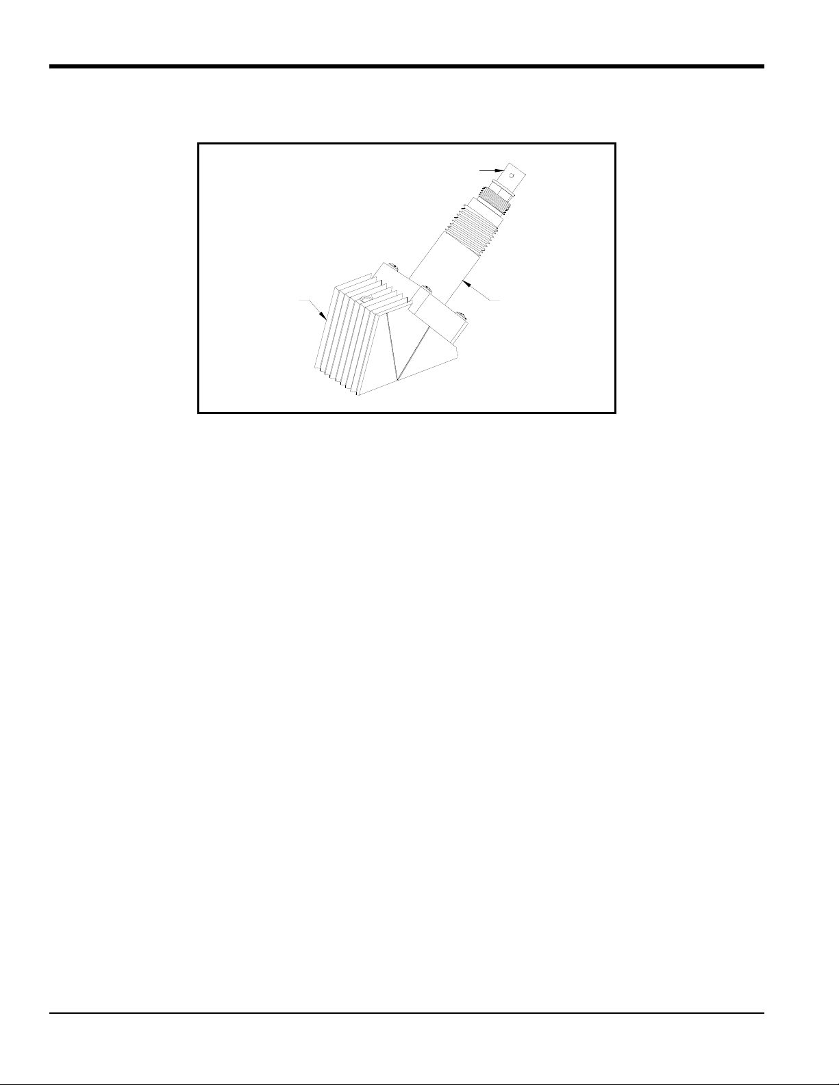
BNC Connector
Transducer
Head
Cover
2. Transducer Construction (cont.)
Figure 1: General C-PT Transducer Assembly
3. Measurement Methods
C-PT transducers can be installed using a number of configurations and clamping fixtures; however, how this is done
largely depends on the flowmeter’s measurement mode. Although many of GE flowmeters have one mode called
Transit-time, some GE flowmeters have an additional measurement mode called TransFlection. Although both
methods use time measurement, the method in which time is measured is different.
3.1 Transit-Time Method
When in Transit-time mode, the flowmeter transmits ultrasonic pulses through a moving liquid. The pulses that travel
in the same direction as the fluid flow (downstream), travel slightly faster than the pulses that travel against the flow
(upstream). The flowmeter uses various digital signal-processing techniques, including cross-correlation, to determine
transit times, and then uses these times to calculate flow velocity.
3.2 TransFlection Method
To measure flow, one transducer transmits a group of pulses (typically 16 pulses) at regular intervals (approximately
5,000 to 10,000 transmissions/sec). The ultrasonic pulses travel through the liquid, reflect off scatterers (i.e. bubbles,
particulates) and the signal is then received by the second transducer.
In essence, these ultrasonic signals are “pictures” taken continuously at the same location in the pipe. The flowmeter
compares these pictures to one another as each picture is received. By comparing (averaging) these pictures, the
flowmeter is able to eliminate stationary objects by subtracting signals that do not appear to move in all or most of the
pictures. The flowmeter measures the time difference between the remaining “moving” objects on each successive
picture. The time difference is called T
and is used to calculate flow.
m
2 C-PT Ultrasonic Flow Transducer Installation Guide
Page 11
4. Couplants
GE supplies an ultrasonic couplant for your C-PT installation. The purpose of the couplant is to provide reliable
transmission of ultrasound between two adjacent solid surfaces. Generally speaking, couplants perform this task by
excluding air from between the adjacent surfaces. Accordingly, the C-PT transducers should be pressed tightly against
the pipe, using hand pressure on the set screw to squeeze the couplant to as thin a film as practical for the given pipe
surface.
The most commonly used couplants in ultrasonic testing are ordinarily satisfactory for any short-term clamp-on
flowmeter application. These couplants include, in general order of preference: gels, grease, propylene glycol, oil,
glycerine, and water. Long-term couplants include grease, epoxy adhesive, and solid rubber-like sheet couplant.
GE provides couplants for both permanent and temporary use as well as for high- and low-temperature applications.
For long-term installations, make sure the couplant does not dry or run out.
Standard couplants supplied from GE are listed in Table 1.
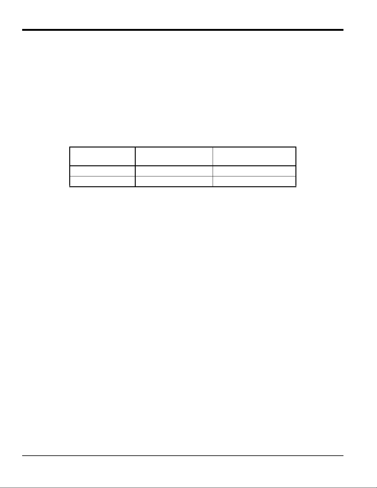
Table 1: Couplants
Part No. Type Temp. Range Use
CPL-1 Standard –40 to 149°F (–40 to 65°C) Semi-Permanent
CPL-2 High/Low Temperature –256 to 500°F (–160 to 260°C) Semi-Permanent
CPL-3 Portable –4 to 140°F (–20 to 60°C) Temporary
CPL-4 Special As Required * Difficult Applications
CPL-7 Epoxy 14 to 122°F (–10 to 50°C) Permanent
CPL-8 Solid Sheet –40 to 446°F (–40 to 130°C) Permanent
* Installations involving hotter or colder temperatures than listed above, may require special
couplants. Consult GE for these applications.
C-PT Ultrasonic Flow Transducer Installation Guide 3
Page 12

5. Installing C-PT Transducers for the Transit-time Method
Installing the C-PT transducers consists of determining the number of traverses, mounting the clamping fixture to the
pipe and then mounting the transducers into the clamping fixture.
Use the sections that follow to properly install the fixture and transducers.
CAUTION! A flowmeter’s accuracy and performance depends on the location, spacing, and alignment of
the transducers. The transducer spacing is unique to your installation.
5.1 Determining the Number of Traverses
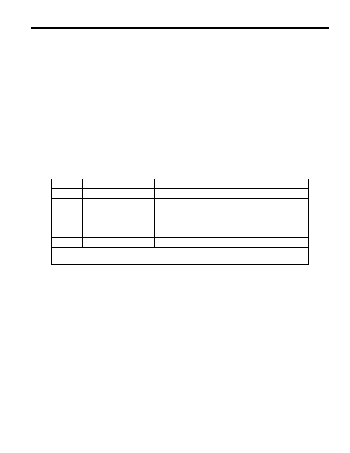
The first step of installation is determining the number of traverses. The transducers can be mounted using one of two
methods (see Figure 2 on page 5):
• Double-traverse method (“V” method) - transducers are mounted on the same side of the pipe and the ultrasonic
signal is bounced from one transducer to the other, off the opposite pipe wall.
• Single-traverse method (“Z” method) - transducers are mounted diagonally across from each other. The ultrasonic
signal is transmitted directly from one transducer to the other, across the pipe.
For pipe diameters from 4 to 20 in., always try the double-traverse method because it is easier to configure and yields
greater accuracy . However , if the pipe has poor inside surface conditions or the fluid is highly attenuating, you may not
be able to obtain a reliable signal. Therefore, you should use the single-traverse method. Typically, you should try the
single-traverse method for pipe diameters greater than 20 in. Spacing of the transducers is calculated by the electronics
after all the installation parameters have been programmed into the flowmeter.
• Universal clamping fixture - page 6
• General clamping fixture (permanent installation) - page 19
• Magnetic clamping fixture - page 30
4 C-PT Ultrasonic Flow Transducer Installation Guide
Page 13
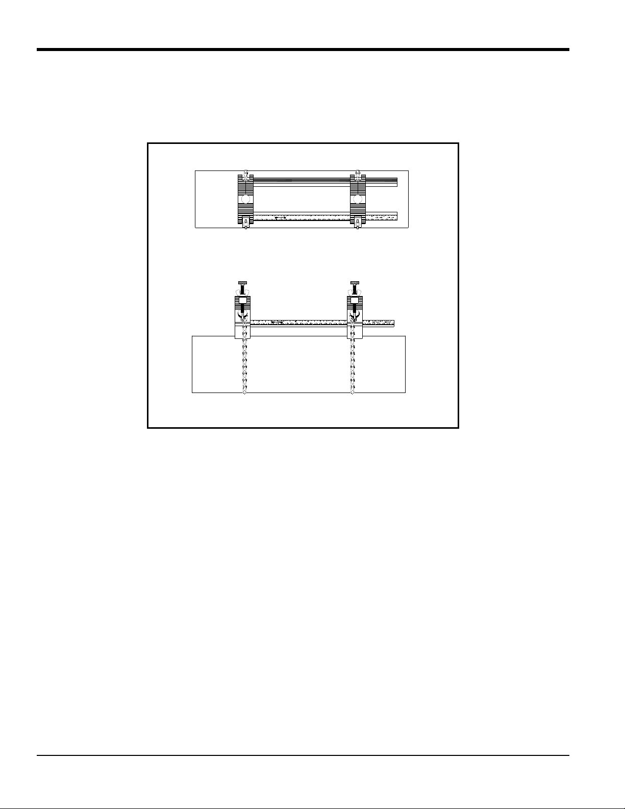
5.1 Determining the Number of Traverses (cont.)
Double Traverse (“V” Method)
Single Traverse (“Z” Method)
Ultrasonic Signal Path
Transducer
Transducer
Transducers
TOP VIEW
TOP VIEW
Figure 2: Double- and Single-Traverse Installations
C-PT Ultrasonic Flow Transducer Installation Guide 5
Page 14
5.2 Installing the Universal Clamping Fixture - UCF
The Universal Clamping Fixture (UCF) acts as a spacing device and a transducer holder. The UCF is available in two
lengths and consists of a number of components. Before you begin installation, you should verify your fixture is the
correct length and familiarize yourself with the fixture components.
5.2a Verifying Fixture Length
Make sure you note the following restrictions for your clamping fixture. The UCF is available in two lengths, 12 in.
and 24 in. (~30.5 cm and ~61 cm). Each size fixture can be installed for a single- or double-traverse method. However,
depending on the method used, there are pipe size restrictions that are outlined in Ta ble 2.
Table 2: UCF Pipe Sizes
Clamping Fixture
Length
12-in. (30.5 cm) 2 to 24 in. (5 to 61 cm) 2 to 12 in. (5 to 30.5 cm)
24-in. (61 cm) 24 to 48 in. (61 to 122 cm) 12 to 24 in. (30.5 to 61 cm)
Note: The mounting chain provided is best suited for your application.
Single-Traverse
Pipe Diameter
Double-Traverse
Pipe Diameter
5.2b Identifying the UCF Components
The UCF has two adjustable short blocks that are used for the double-traverse method. Two slide tracks connect the
blocks. A ruler attached to one of the tracks helps set the transducer spacing. For single-traverse methods, a long block
is also used.
The blocks are used to hold the transducers in position for accurate measurement. The UCF is chained or strapped
around the pipe. The blocks are positioned using the spacing dimension calcul ated by the flowmeter. Then the
transducers are mounted into the blocks. Figure 3 on page 7 shows the short and long blocks.
The transducer installation consists of mounting the UCF to the pipe and then mounting the transducers into the fixture.
Refer to the appropriate section that follows for instructions:
• Double-traverse Method - page 8
• Single-traverse Method - page 11
6 C-PT Ultrasonic Flow Transducer Installation Guide
Page 15
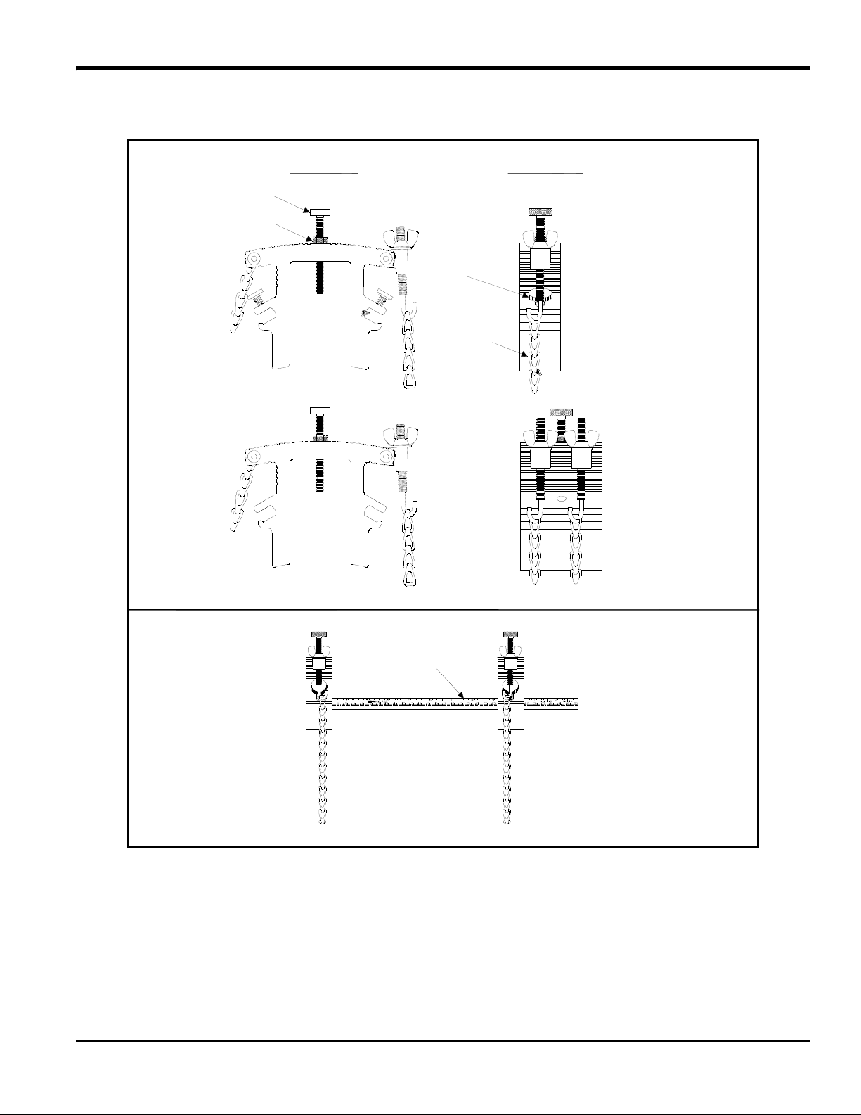
5.2b Identifying the UCF Components (cont.)
End View
Side View
Counter Nut
Short Block
1 Screw Hook
Long Block
2 Screw Hooks
Thumbscrew
Chain
Example with Short Blocks
Slide Track
(fixed and adjustable)
Pressure Bolt
Figure 3: Components of the UCF
C-PT Ultrasonic Flow Transducer Installation Guide 7
Page 16
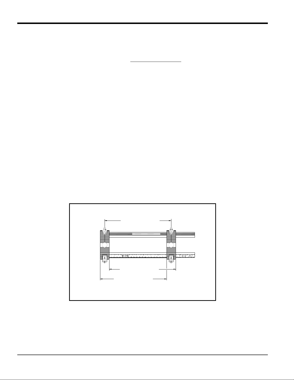
S = Spacing
S = Spacing
S = Spacing
Select one method to set the spacing
Centerline
Centerline
5.2c The Double-Traverse Method -UCF
Note: The instructions in this section can also be used for a multiple-traverse method. However, you must use an
EVEN number of traverses. The distance the signal travels from one side of the pipe wall to the opposite side of
the pipe wall is considered one traverse. For more than two traverses
There are three advantages to using the double-traverse method:
, consult the GE factory.
• Accuracy is improved because the signal is in the fluid longer than with a single-traverse.
• This configuration can reduce some effect of an underdeveloped flow profile.
• If there is enough pipe length available, the double-traverse fixture is easier to install.
The procedure for mounting the UCF involves setting the transducer spacing and fastening the fixture on the pipe.
Please note you will only need the short block assembly for a double-traverse installation; the long block is not used.
1. Obtain the transducer spacing dimension S, as described in the programming section of the Startup Guide.
2. Be sure the location you have chosen for the installation has at least 10 pipe diameters of straight, undisturbed flow
upstream and 5 pipe diameters downstream of the measurement point.
3. Prepare the pipe where you intend to pla ce the clamping fixture by making sure it is clean and free of loose
material. Sanding, though usually not required, may be necessary to take off any high spots. When sanding, be
careful to preserve the original curvature of the pipe.
4. Using the attached ruler, move the blocks so they are a distance S from each other . Use the pressure bolt or the ends
of the blocks as reference points.
.
8 C-PT Ultrasonic Flow Transducer Installation Guide
Page 17
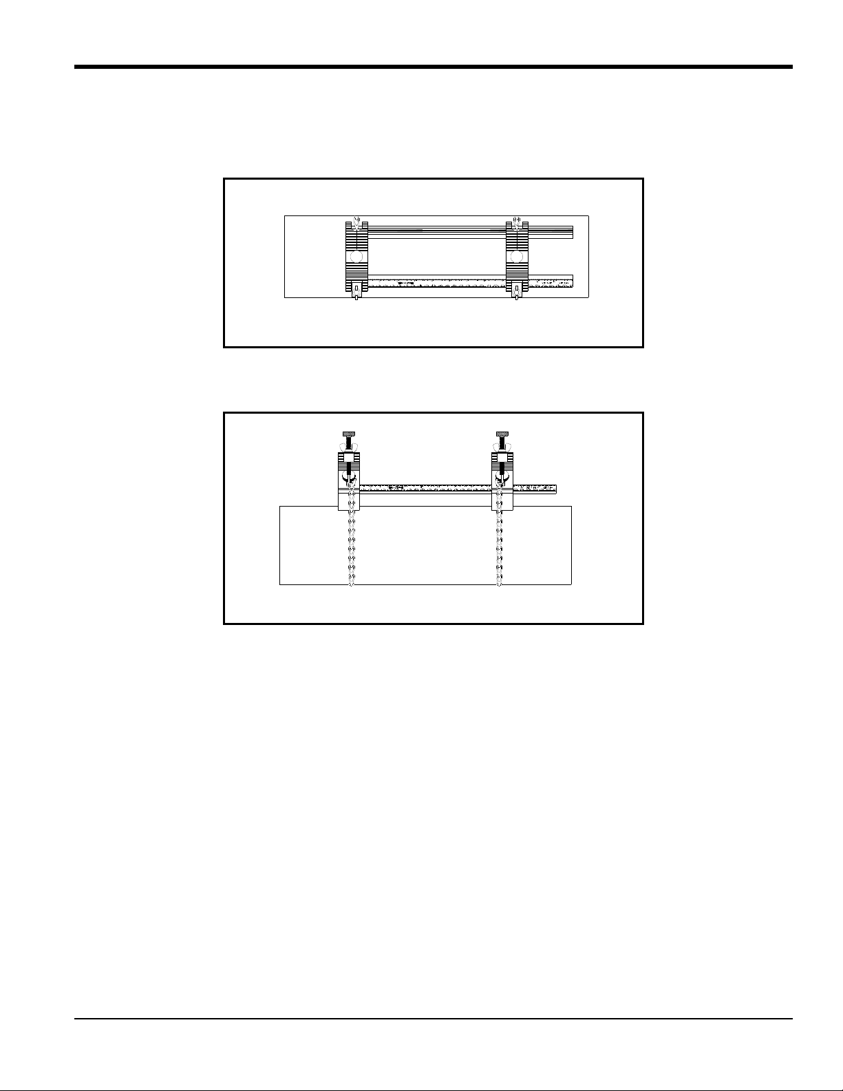
5.2c The Double-Traverse Method -UCF (cont.)
Side View
Top View
5. Position the clamping fixture along the horizontal plane of the pipe, but not on the top or bottom. Make sure the
chains on both blocks are on the same side of the fixture and are op posite the ruler.
6. Wrap the chain around the pipe and fasten the chain on the J screw hook on the opposite side of the block. Do this
for both blocks.
7. Using the screw hook on the blocks, tighten the chains until the fixture is secured snugly to the side of the pipe.
Note: Make sure the chains are perpendicular to the clamping fixture and are not twisted. If the chains are slanted,
the slack may cause the fixture to move around. The slack may also change the transducer spacing after the
transducers are mounted.
C-PT Ultrasonic Flow Transducer Installation Guide 9
Page 18
Side View
Top View
5.2c The Double-Traverse Method -UCF (cont.)
Figure 4 shows a completed double-traverse installation without transducers. Proceed to Mounting Transducers into
the UCF
on page 16.
Figure 4: A Double-Traverse Clamping Fixture Installation (w/o transducers)
10 C-PT Ultrasonic Flow Transducer Installation Guide
Page 19
5.2d The Single-Traverse Method - UCF
Line
Top of Pipe
Side View
Note: The instructions in this section can also be used for a multiple-traverse method. However, you must use an
ODD number of traverses. The distance the signal travels from one side of the pipe wall to the opposite side of
the pipe wall is considered one traverse.
The procedure for mounting the UCF for the single-traverse method requires a long block and two short blocks. The
long block is fastened to the pipe first and then the short block assembly is properly aligned and fastened at 180° from
the long block.
You will need a marker or scribe to locate and mark the transducer locations on the pipe. Do the following:
1. Obtain the transducer spacing dimension S, as described in the programming section of the Startup Guide.
2. Be sure the location you have chosen for the installation has at least 10 pipe diameters of straight, undisturbed flow
upstream and 5 pipe diameters downstream of the measurement point.
3. Prepare the pipe where you intend to place the UCF by making sure it is clean and free of loose material. Sanding,
though usually not required, may be necessary to take off any high spots. However, be careful to preserve the
original curvature of the pipe and not to eradicate the marks on the pipe.
4. Find the top of the pipe and use a level to draw a line parallel to the pipe’s axis.
C-PT Ultrasonic Flow Transducer Installation Guide 11
Page 20
Spacing
Mark
Mark
Side View
Spacing
Crossmark
Side View
Spacing
Crossmark
Side View
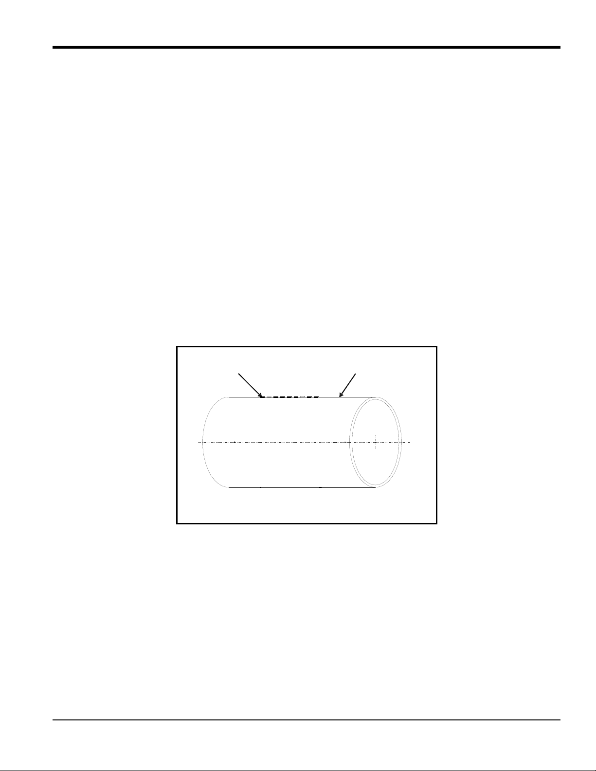
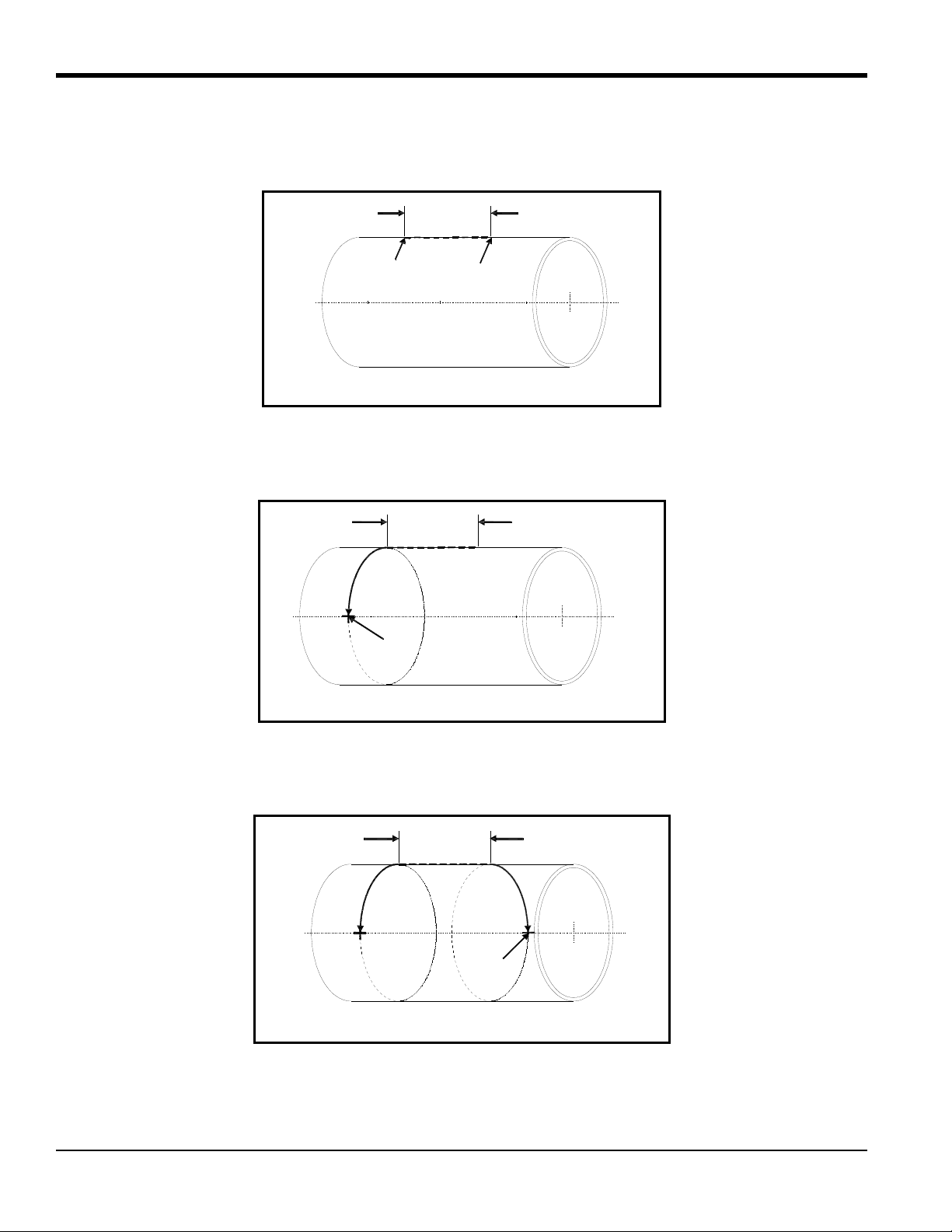
5.2d The Single-Traverse Method -UCF (cont.)
5. Make two marks on the line equal to the transducer spacing distance S, as calculated by the meter.
6. From one of the marks, measure around the circumference of the pipe a distance equal to one quarter the pipe’s
circumference and make a crossmark with the marker or scribe.
7. From the other mark, go in the other direction around the pipe for on e quarter the circumference and make another
crossmark.
12 C-PT Ultrasonic Flow Transducer Installation Guide
Page 21
5.2d The Single-Traverse Method -UCF (cont.)
Fasten Chains
Top View
Fasten Chains
Top View
Top View
Tighten Screw
Hooks
Tighten
Screw Hooks
Top View
8. Center the long block over one of the crosssmarks on the pipe. Align the long block so that the pressure bolt is over
the center of the crossmark. Fasten the block by wrapping both chains around the pipe and fastening the chains to
the screw hooks on the opposite side of the block.
9. Use the wing nuts to tighten the chains on the long block until it is secured snugly to the pipe.
Note: Make sure both chains are perpendicular to the bottom of the block and are not twisted. If the chains are
slanted, the slack will cause the block to slide.
C-PT Ultrasonic Flow Transducer Installation Guide 13
Page 22
Top View
Short Block
Crossmark
Crossmark
(One of two)
Crossmark
Crossmark
Short Block
(one of two)
Top View
Top View
5.2d The Single-Traverse Method -UCF (cont.)
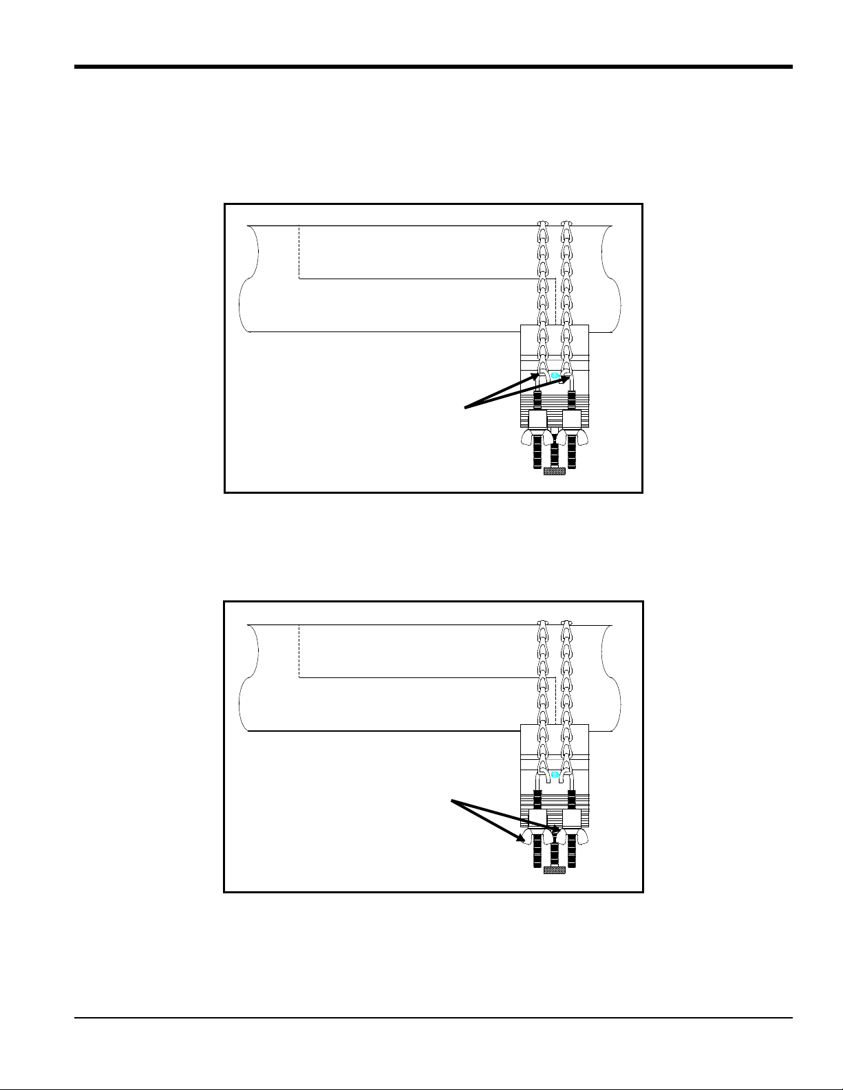
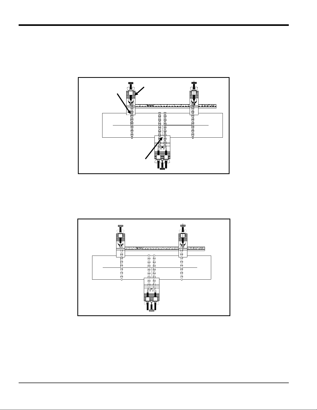
10. Position the clamping fixture rails so that one of the short blocks is placed over the remaining crossmark on the
opposite side of the pipe and the pressure bolt is over the center of the crossmark. Make sure the block does not lie
on top of the chains of the long block.
11. Wrap the chain around the pipe and fasten the chain to the screw hook on the opposite side of the block. Do this for
both short blocks.
Note: Make sure the chains on both blocks are on the same side of the fixture and are opposite the ruler.
12. Tighten the pressure bolt all the way down on the short block that is NOT positioned over the crossmark. This will
act as a reminder to not install the transducer in that block.
14 C-PT Ultrasonic Flow Transducer Installation Guide
Page 23

5.2d The Single-Traverse Method - UCF (cont.)
Side View
Top View
S
13. Use the screw hooks to tighten the chains on the fixed and adjustable blocks until the blocks are secured snugly to
the pipe.
Note: Make sure both chains are perpendicular to the clamping fixture and are not twisted. If the chains are slanted,
the slack will cause the blocks to slide. The slack may also change the transducer spacing after the transducers
are mounted.
Figure 5 shows a completed single-traverse installation without transducers. Proceed to Mounting Transducers into the
UCF
on page 16.
Figure 5: Single-Traverse Clamping Fixture Installation without Transducers
C-PT Ultrasonic Flow Transducer Installation Guide 15
Page 24

5.2e Mounting Transducers into the UCF
The last step of installation is mounting the transducers into the clamping fixture. C-PT transducers are manufactured
with a dimple on top of the transducer body. In addition, there are scribe marks on each side.
To mount the transducers into the UCF, use the following steps:
1. Apply a thread sealant to the transducer threads. A sealant is not required within the US, however, a sealant must be
used in European Communities.
2. Before mounting the transducers, thread the junction box onto the end of the transducer with the BNC connector.
Ensure that at least five full threads are engaged. Make sure to orient the cover of the junction box so it is
accessible to make cable connections once the box is installed.
3. Take one of the transducers and apply a thin bead of couplant down the center of its face approximately the size of
a toothpaste bead.
IMPORTANT: To prevent the loss of couplant, do not slide the transducer with couplant along the surface of the pipe
when mounting.
16 C-PT Ultrasonic Flow Transducer Installation Guide
Page 25

5.2e Mounting Transducers into the UCF (cont.)
Top View
Flow
Top View
Pressure Bolt
4. Place the transducers into the blocks. Make sure the junction box faces away from the block as shown below.
Note: If the transducer cables are alr eady connected, you must determine the upstr eam and do wnstr eam directions of
the pipe and place the transducers into the appropriate blocks.
5. Use the pressure bolt to secure the transducer in place. The pressure bolt should fit into the dimple. Hand-tighten
enough to hold the transducer in place. Do not overtighten so that the fixture lifts off the pipe.
CAUTION FOR ATEX CERTIFIED INSTALLATIONS
To ensure against impact to the transducer face, it must always be mounted flush to the pipe.
C-PT Ultrasonic Flow Transducer Installation Guide 17
Page 26

Double-Traverse Installation (Top View)
Single-Traverse Installation (Top View)
5.2e Mounting Transducers into the UCF (cont.)
6. Tighten the counter nut on the pressure bolt (see Figure 3 on page 7).
IMPORTANT: When using the UCF in a pipe location with possible mechanical vibration, the locking nut must be used
to secure the position of the pr essure bolt on the transducer after the bolt has been hand-tightened into the
transducer dimple. For additional resistance to vibration a thread lock compound or a stainless steel
washer and lock washer may also be used. These items can be ordered from GE by requesting a special
clamping fixture and specifying either the thread lock or the washers.
7. Repeat Steps 1 to 6 to mount the other transducer in the remaining block.
8. Tighten the thumbscrews on the short blocks to make sure the block is secure on the rail. See Figure 6 on page 18
for completed UCF installations.
WARNING! Before performing the next step make sure the power to the flowmeter electronics is
disconnected.
9. Make transducer cable connections as described in the Installation chapter of the Startup Guide.
Figure 6: Completed UCF Installations with Transducers
Note: If you have mounted the transducers into the UCF properly, the two transducer cable connectors will face
away from each other as shown in Figure 6.
18 C-PT Ultrasonic Flow Transducer Installation Guide
Page 27

5.3 Installing the General Clamping Fixture - GCF
End View
Side View
The General Clamping Fixture (GCF) acts as a permanent transducer holder. The fixture has two blocks that are used
for double- and single-traverse methods. Steel straps secure the blocks to the pipe for a permanent installation.
The blocks are positioned properly using the spacing dimension calculated by the flowmeter. Then the transducers are
mounted into the blocks. Figure 7 shows a long block.
The transducer installation consists of mounting the GCF to the pipe and then mounting the transducers into the blocks.
Refer to the appropriate section that follows for instructions:
• Double-traverse Method - below
• Single-traverse Method - page 23
Figure 7: General Clamping Fixture Block
5.3a The Double-Traverse Method - GCF
Note: The instructions in this section can also be used for a multiple-traverse method. However, you must use an
EVEN number of traverses. The distance the signal travels from one side of the pipe wall to the opposite side of
the pipe wall is considered one traverse. For more than two traverses
There are three advantages in using the double-traverse method:
, consult the GE factory.
• Accuracy is improved because the signal is in the fluid longer than with a single-traverse.
• This configuration can reduce some effects of an underdeveloped flow profile.
• If there is enough pipe length available, the double-traverse fixture is easier to install.
C-PT Ultrasonic Flow Transducer Installation Guide 19
Page 28

Line
Top of Pipe
Side View
5.3a The Double-Traverse Method - GCF (cont.)
The procedure for mounting the GCF invo lves marking t he pipe for the desired spacing, fastening the clamping fixture
on the pipe and then mounting the transducers into the fixture.
You will need a level and a marker or scribe to locate and mark the transducer locations on the pipe.
1. Obtain the transducer spacing dimension S, as described in the programming section of the Startup Guide.
2. Be sure the location you have chosen for the installation has at least 10 pipe diameters of straight, undisturbed flow
upstream and 5 pipe diameters downstream of the measurement point.
3. Prepare the pipe where you intend to pla ce the clamping fixture by making sure it is clean and free of loose
material. Sanding, though usually not required, may be necessary to take off any high spots. Be careful to preserve
the original curvature of the pipe.
4. Find the top of the pipe and use a level to draw a line parallel to the pipe’s axis.
20 C-PT Ultrasonic Flow Transducer Installation Guide
Page 29

5.3a The Double-Traverse Method - GCF (cont.)
Spacing
Mark
Mark
Side View
Spacing
Crossmarks
Side View
Top View
Turnbuckles
5. Make two marks on the line equal to the transducer spacing distance S, as calculated by the meter.
6. From each of the marks, measure around the circumference of the pipe a distance equal to one quarter the pipe’s
circumference. Make a crossmark with a marker or scribe.
7. Center one of the blocks over one of the crossmarks on the pipe. Align the block so that the pressure bolt is over the
center of the mark. Secure the block by wrapping the two straps around the block and pipe and tightening them.
Make sure the turnbuckles are at least 1/2 pipe diameter away from the clamping fixture.
C-PT Ultrasonic Flow Transducer Installation Guide 21
Page 30

Top View
Top View
End View
5.3a The Double-Traverse Method - GCF (cont.)
8. Repeat Step 7 to install the other block over the other crossmark.
Note: Make sure both straps are perpendicular to the bottom of the block. If the straps are slanted, the slack will
cause the block to slide. The slack may also change the transducer spacing after the transducers are mounted.
Figure 8 shows a double-traverse installation without transducers. Proceed to Mounting Transducers into the GCF
page 27.
on
Figure 8: A Double-Traverse GCF Installation without Transducers
22 C-PT Ultrasonic Flow Transducer Installation Guide
Page 31

5.3b The Single-Traverse Method - GCF
Line
Top of Pipe
Side View
Spacing
Mark
Mark
Side View
Note: The instructions in this section can also be used for a multiple-traverse method. However, you must use an
ODD number of traverses. The distance the signal travels from one side of the pipe wall to the opposite side of
the pipe wall is considered one traverse.
The procedure for mounting the GCF involves marking the pipe for the desired spacing, fastening the fixture to the
pipe and then mounting the transducers into the fixture.
You will need a level and marker or scribe to locate the transducers on the pipe.
1. Obtain the transducer spacing dimension S, as described in the programming section of the Startup Guide.
2. Be sure the location you have chosen for the installation has at least 10 pipe diameters of straight, undisturbed flow
upstream and 5 pipe diameters downstream of the measurement point.
3. Prepare the pipe where you intend to place the GCF by making sure it is clean and free of loose material. Sanding,
though usually not required, may be necessary to take off any high spots. Be careful to preserve the original
curvature of the pipe and not to eradicate the marks on the pipe.
4. Find the top of the pipe and use a level to draw a line parallel to the pipe’s axis.
5. Make two marks on the line equal to the transducer spacing distance S, as calculated by the meter.
C-PT Ultrasonic Flow Transducer Installation Guide 23
Page 32

Spacing
Crossmark
Side View
Spacing
Crossmark
Side View
5.3b The Single-Traverse Method - GCF (cont.)
6. From one of the marks, measure around the circumference of the pipe a distance equal to one quarter the pipe’s
circumference. Make a crossmark with a marker or scribe.
7. From the other mark, go in the opposite direction around the pipe for one quarter the circumference and make
another crossmark.
24 C-PT Ultrasonic Flow Transducer Installation Guide
Page 33

5.3b The Single-Traverse Method -GCF (cont.)
Top View
Turnbuckles
Top View
8. Center one of the blocks over one of the crossmarks on the pipe. Align the block so that the pressure bolt is over the
center of the crossmark. Secure the block by wrapping two straps around the block and pipe and tightening them.
Make sure the turnbuckles are at least 1/2 pipe diameter away from the clamping fixture.
9. Repeat Step 8 to install the other block over the other punch mark.
Note: Make sure both straps are perpendicular to the bottom of the block. If the straps are slanted, the slack will
cause the block to slide. The slack may also change the transducer spacing after the transducers are mounted.
C-PT Ultrasonic Flow Transducer Installation Guide 25
Page 34

Top View
End View
5.3b The Single-Traverse Method -GCF (cont.)
Figure 9 shows a single-traverse installation without transducers. Proceed to Mounting Transducers into the GCF
page 27.
on
Figure 9: A Single-Traverse GCF Installation without Transducers
26 C-PT Ultrasonic Flow Transducer Installation Guide
Page 35

5.3c Mounting Transducers into the GCF
The last step of installation is mounting the transducers into the clamping fixture. C-PT transducers are manufactured
with a dimple on top of the transducer body. In addition, there are scribe marks on each side.
To mount the transducers into the GCF, use the following steps:
1. Apply a thread sealant to the transducer threads. A sealant is not required within the US, however, a sealant must be
used in European Communities.
2. Before mounting the transducers, thread the junction box onto the end of the transducer with the BNC connector.
Ensure that at least five full threads are engaged. Make sure to orient the cover of the junction box so it is
accessible to make cable connections once the box is installed.
3. Take one of the transducers and apply a thin bead of couplant down the center of its face approximately the size of
a toothpaste bead.
IMPORTANT: To prevent the loss of couplant, do not slide the transducer with couplant along the surface of the pipe
when mounting.
C-PT Ultrasonic Flow Transducer Installation Guide 27
Page 36

Top View
Counter Nut
5.3c Mounting Transducers into the GCF (cont.)
4. Place the transducers in the appropriate blocks. Make sure the transducers are oriented as shown below.
CAUTION FOR ATEX CERTIFIED INSTALLATIONS
To ensure against impact to the transducer face, it must always be mounted flush to the pipe.
Note: If the transducer cables are alr eady connected, you must determine the upstream and downstream directions of
the pipe and place the transducers into the appropriate blocks.
5. Use the pressure bolt to secure the transducer in place. The pressure bolt should fit into the dimple. Hand-tighten
enough to hold the transducer in place. Do not overtighten so that the fixture lifts off the pipe.
6. Tighten the counter nut on the pressure bolt (see above).
IMPORTANT: When using the GCF in a pipe location with possible mechanical vibration, the locking nut must be used
to secure the position of the pr essure bolt on the transducer after the bolt has been hand-tightened into the
transducer dimple. For additional resistance to vibration a thread lock compound or a stainless steel
washer and lock washer may also be used. These items can be order ed from GE by requesting a "special"
clamping fixture and specifying either the thread lock or the washers.
7. Repeat Steps 1 to 6 to mount the other transducer in the remaining block. See Figure 10 on page 29 for completed
installations.
28 C-PT Ultrasonic Flow Transducer Installation Guide
Page 37

5.3c Mounting Transducers into the GCF (cont.)
Double-Traverse Installation (Top View)
Single-Traverse Installation (Top View)
WARNING! Before performing the next step make sure the power to the flowmeter electronics is
disconnected.
8. Make transducer cable connections as described in the Installation chapter of the Startup Guide.
Figure 10: Completed GCF Installations with Transducers
Note: If you have mounted the transducers into GCF properly, the two transducer cable connectors will face away
from each other as shown in Figure 10.
C-PT Ultrasonic Flow Transducer Installation Guide 29
Page 38

Magnetic Block
Transducer Block
Pressure Bolt
Thumbscrews
ON/OFF Switch
Rails
Counter Nut
Optional Safety Chain
5.4 Installing the Magnetic Clamping Fixture - MCF
The Magnetic Clamping Fixture (MCF) is used to fasten transducers to the pipe at the proper spacing without chains or
straps. The MCF is used on ferrous pipe materials only.
Different fixtures are used for a single- and double-traverse installation. Each type of MCF has magnets at either end of
the fixtures. When the magnets are turned ON, the fixture magnetically “clamps” to the pipe wall.
To properly mount the MCF, you should become familiar with the components of each type of fixture.
5.4a Identifying the MCF Components
Refer to Figure 11 to identify these components, then refer to one of the following sections to install the clamping
fixture:
• Double-traverse Method - page 31
• Single-traverse Method - page 33
Figure 11: Transducer Block and Magnetic Block
30 C-PT Ultrasonic Flow Transducer Installation Guide
Page 39

5.4b The Double-Traverse Method - MCF
S
S
Select one method to set spacing
S
The Double-Traverse MCF consists of two blocks connected by two rods (one of the two rods acts as a scale or ruler to
help you properly space transducers). Both blocks are adjustable. This type of fixture has two transducer blocks and
like the magnetic blocks, both are adjustable.
The procedure for mounting the MCF involves setting the transducer spacing and then securing the fixture to the pipe.
WARNING! Do not use the MCF at temperatures that exceed 120°F (49°C), or the fixture will fall off the pipe.
To install the MCF in a double-traverse configuration:
Note: The instructions that follow can be used for a multiple-traverse method. However, you must use an EVEN
number of traverses. The distance the signal travels from one side of the pipe wall to the opposite side of the
pipe wall is considered one traverse.
1. Obtain the transducer spacing dimension S, as described in the programming section of the Startup Guide.
2. Be sure the location you have chosen for the installation has at least 10 pipe diameters of straight, undisturbed flow
upstream and 5 pipe diameters downstream of the measurement point.
3. Prepare the pipe where you intend to place the clamping fixture by making sure it is clean and free of loose
material. Sanding, though usually not required, may be necessary to take off any high spots. Be careful to preserve
the original curvature of the pipe.
4. Using the scale on the rod, move the blocks so they are located a distance equal to the spacing dimension from each
other. To move the block, loosen the red thumb screws, slide the block to the desired location and tighten the thumb
screws. Use the pressure bolt or the edge of the block as the measuring point for the block.
C-PT Ultrasonic Flow Transducer Installation Guide 31
Page 40

S
At least 4”
S
S
Top View
5.4b The Double-Traverse Method - MCF (cont.)
5. Locate the magnetic blocks at least 4 in. away from the transducer blocks. This will ensure that there is enough
clearance to mount the transducers in the blocks. Move the adjustable magnetic block in the same manner as the
transducer block.
6. Position the clamping fixture along the horizontal plane of the pipe. If the pipe is horizontal, do not place the
fixture on the top or bottom of the pipe.
7. Turn the switches on each magnet to the ON position.
8. If provided, secure the safety chain. The safety chain prevents the fixture from falling of the pipe in the event the
magnet releases.
9. Proceed to Mounting Transducers into the MCF
on page 37.
32 C-PT Ultrasonic Flow Transducer Installation Guide
Page 41

5.4c The Single-Traverse Method - MCF
Line
Top of Pipe
Side View
The Single-Traverse MCF consists of two parts. Each part is made up of two magnetic blocks which are connected by
two rods. In addition, a sliding transducer block, which is used to hold the transducer in proper alignment, is positioned
on the two rods. Each part is positioned on the pipe to face 180
Note: In some cases, a magnetic clamping fixture with two transducer blocks is used.
The procedure for mounting the MCF involves marking the pipe and then securing the fixtures to the pipe.
WARNING! Do not use magnetic fixtures at temperatures that exceed 120°F (49°C), or the fixture will fall off
the pipe.
To install the MCF in a single-traverse configuration:
Note: The instructions in this section can also be used for a multiple-traverse method. However, you must use an
ODD number of traverses. The distance the signal travels from one side of the pipe wall to the opposite side of
the pipe wall is considered one traverse.
1. Obtain the transducer spacing dimension S, as described in the programming section of the Startup Guide.
o
opposite each other.
2. Be sure the location you have chosen for the installation has at least 10 pipe diameters of straight, undisturbed flow
upstream and 5 pipe diameters downstream of the measurement point.
3. Prepare the pipe where you intend to place the MCF by making sure it is clean and free of loose material. Sanding,
though usually not required, may be necessary to take off any high spots. Be careful to preserve the original
curvature of the pipe and not to eradicate the marks on the pipe.
4. Find the top of the pipe and use a level to draw a line parallel to the pipe’s axis.
C-PT Ultrasonic Flow Transducer Installation Guide 33
Page 42

Spacing
Mark
Mark
Side View
Spacing
Crossmark
Side View
Spacing
Crossmark
Side View
5.4c The Single-Traverse Method - MCF (cont.)
5. Make two marks on the line separated by the transducer spacing distance S, as calculated by the meter.
6. From one of the marks, measure around the circumfere nc e of the pipe a distance equal to one quarter the pipe’s
circumference. Use a marker or scribe to make a crossmark.
7. From the other mark, go in the opposite direction around the pipe for one quarter the circumference and make
another crossmark.
34 C-PT Ultrasonic Flow Transducer Installation Guide
Page 43

5.4c The Single-Traverse Method - MCF (cont.)
Thumbscrew
Pressure Bolt
Top View
8. On one of the fixtures, position the transducer block anywhere along the rods, being sure to leave enough room on
either side to easily insert the transducer. To move the block, loosen the red thumbscrews, slide the block to the
desired location and tighten the thumbscrews. Use the pressure bolt as the measuring point for the block. Repeat
for the other fixture.
Note: If you are using a fixtur e with two transducer blocks, adjust one block as described above and push the unused
block all the way to one side of the rail. Tighten the pressure bolt all the way down on the unused block. This
will act as a reminder to not install the transducer in that block.
9. Center the block over one of the marks on the pipe. Align it such that the pressure bolt on the transducer block is
right over the center of the crossmark.
.
10. Turn the switches on each magnet to the ON position.
C-PT Ultrasonic Flow Transducer Installation Guide 35
Page 44

Top View
5.4c The Single-Traverse Method - MCF (cont.)
11. Repeat Steps 9 and 10 for the other fixture on the opposite pipe marking.
12. If provided, secure the safety chain. The safety chain prevents the fixture from falling off the pipe in the event the
magnet releases.
Proceed to Mounting Transducers into the MCF
on page 37.
36 C-PT Ultrasonic Flow Transducer Installation Guide
Page 45

5.4d Mounting Transducers into the MCF
The last step of installation is mounting the transducers into the clamping fixture. C-PT transducers are manufactured
with a dimple on top of the transducer body. In addition, it also has scribe marks on each side.
To mount the transducers into the MCF, use the following steps:
1. Apply a thread sealant to the transducer threads. A sealant is not required within the US, however, a sealant must be
used in European Communities.
2. Before mounting the transducers, thread the junction box onto the end of the transducer with the BNC connector.
Ensure that at least five full threads are engaged. Make sure to orient the cover of the junction box so it is
accessible to make cable connections once the box is installed.
3. Take one of the transducers and apply a thin bead of couplant down the center of its face approximately the size of
a toothpaste bead.
IMPORTANT: To prevent the loss of couplant, do not slide the transducer with couplant along the surface of the pipe
when mounting.
C-PT Ultrasonic Flow Transducer Installation Guide 37
Page 46

Top View
Downstream Transducer
Flow
Top View
Pressure Bolt
Counter Nut
5.4d Mounting Transducers into the MCF (cont.)
4. Place the transducers in the appropriate blocks. Make sure the transducers are oriented as shown below.
CAUTION FOR ATEX CERTIFIED INSTALLATIONS
To ensure against impact to the transducer face, it must always be mounted flush to the pipe.
Note: If the transducer cables are alr eady connected, you must determine the upstream and downstream directions of
the pipe and place the transducers into the appropriate blocks.
5. Use the pressure bolt to secure the transducer in place. The pressure bolt should fit into the dimple. Hand-tighten
enough to hold the transducer in place. Do not overtighten so that the fixture lifts off the pipe.
WARNING! Do not tighten the pressure bolt so that the magnet separates from the pipe.
38 C-PT Ultrasonic Flow Transducer Installation Guide
Page 47

5.4d Mounting Transducers into the MCF (cont.)
Double-Traverse Installation (Top View)
Single-Traverse Installation (Top View)
Double-Traverse Installation (Top View)
Single-Traverse Installation (Top View)
6. Tighten the counter nut on the pressure bolt (see drawing in step 5 on page 38).
IMPORTANT: When using the MCF in a pipe location with possible mechanical vibration, the locking nut must be used
to secure the position of the pr essure bolt on the transducer after the bolt has been hand-tightened into the
transducer dimple. For additional resistance to vibration a thread lock compound or a stainless steel
washer and lock washer may also be used. These items can be order ed from GE by requesting a "special"
clamping fixture and specifying either the thread lock or the washers.
7. Repeat Steps 1 to 6 to mount the other transducer in the remaining block. See Figure 12 for completed installations.
WARNING! Before performing the next step make sure the power to the flowmeter electronics is
disconnected.
8. Make transducer cable connections as described in the Installation chapter of the Startup Guide.
WARNING! If your fixture is installed at an elevated location, GE recommends securing the fixture with the
optional safety chain or a tether/leash to prevent injury if the fixture falls off the pipe.
Figure 12: Completed MCF Installations with Transducers
Note: If you have mounted the transducers into the MCF properly, the two transducer cable connectors will face
away from each other as shown in Figure 12.
C-PT Ultrasonic Flow Transducer Installation Guide 39
Page 48

6. Installing C-PT Transducers for the TransFlection Method
Before making measurements using the TransFlection method, you must install the transducers properly. Like transit
time measurement, TransFlection requires two transducers. The transducers are mounted on the pipe using a
TransFlection Mode Clamping Fixtur e (TMCF) that is clamped around the pipe with a chain or strap. Since the TMCF
can be used to install transducers up to 180
placement of the fixture.
Use this guide to properly install the fixture and transducers on your pipe.
6.1 Mounting the TransFlection Mode Clamping Fixture - TMCF
The transducers can be mounted up to 180° apart around the circumference of the pipe. The angle between the
transducers is dependent on the size of the pipe. Generally, transducers are located opposite each other (180°) on pipes
2 to 4 inches in diameter. For pipes 4 inches in diameter and larger, or on smaller pipes (i.e. 2 to 4 inches in diameter)
with heavy concentrations of two-phase liquid present, the transducers are located right next to each other.
Refer to one of the following sections to properly mount the transducers and fixture.
o
apart around the pipe, different fixtures are used depending on the
• Mounting the TMCF in <180
• Mounting the TMCF in 180
o
Configuration - page 41
o
Configuration - page 44
40 C-PT Ultrasonic Flow Transducer Installation Guide
Page 49

6.1a Mounting the TMCF in a <180o Configuration
Pressure Bolt
Screw Hooks
Quick-Release Pin
Brackets
Blocks
Quick-Release Pin
Use the following steps to properly mount and install the transducers in a <180o configuration.
1. Familiarize yourself with the components of the TMCF as shown below.
2. Prepare the pipe where you intend to place the TMCF by making sure it is clean and free of loose material.
Sanding, though usually not required, may be necessary to take off any high spots. Be careful to preserve the
original curvature of the pipe.
3. If not already connected, connect the bracket from each block using the quick-release pin. The distance between
the blocks depends on where you are placin g them on the pipe. You only need to estimate the distance. If necessary ,
the distance can be adjusted later.
C-PT Ultrasonic Flow Transducer Installation Guide 41
Page 50

End View
End View
6.1a Mounting the TMCF in a <180o Configuration (cont.)
4. Position the fixture with the two blocks in a common axial plane of the pipe, but not on the top or bottom of the
pipe.
5. Wrap the chains around the pipe and fasten them to the screw hooks on the other block. If necessary, adjust the
distance between the blocks.
Note: Make sure the chains are not twisted.
42 C-PT Ultrasonic Flow Transducer Installation Guide
Page 51

6.1a Mounting the TMCF in a <180o Configuration (cont.)
Side View
End View
6. Tighten and/or loosen the chains using the screw hooks to fine tune the angle between the blocks. The blocks
should fit snugly against the pipe.
Note: Make sure the blocks are in a common axial plane so the chains are not slanted. If the chains are slanted, the
slack will allow the fixture to move around.
7. Proceed to Mounting the Transducers into the TransFlection Mode Clamping Fixture - TMCF on page 37.
Figure 13 shows an example of a completed <180
o
installation without transducers.
o
Figure 13: Completed <180
C-PT Ultrasonic Flow Transducer Installation Guide 43
Installation without Transducers
Page 52

Pressure Bolt
Screw Hooks
Front View
Side View
6.1b Mounting the TMCF in a 180o Configuration
Use the following steps to properly mount and install the transducers in a 180o configuration.
1. Familiarize yourself with the components of the TMCF as shown below.
2. Prepare the pipe where you intend to place the TMCF by making sure it is clean and free of loose material.
Sanding, though usually not required, may be necessary to take off any high spots. Be careful to preserve the
original curvature of the pipe.
3. If not already connected, co nnect the chain from one block to the screw hooks on the other block. The distance
between the blocks depends on where you are placing them on the pipe. You only need to estimate the distance. If
necessary, the distance can be adjusted later.
44 C-PT Ultrasonic Flow Transducer Installation Guide
Page 53

6.1b Mounting the TMCF in a 180o Configuration (cont.)
End View
End View
End View
4. Position the blocks in a common plane of the pipe, but not on the top or bottom. The blocks should be opposite
each other (180
o
).
5. Wrap the remaining chains around the pipe and fasten them to the screw hooks on the other block. Make sure the
chains on either side of the pipe are approximately the same length.
6. Tighten and/or loosen the chains using the screw hooks on both blocks to fine tune the angle between the blocks.
Make sure the chains are not twisted or slanted.
7. Proceed to Mounting the Transducers into the TransFlection Mode Clamping Fixture - TMCF on page 47.
C-PT Ultrasonic Flow Transducer Installation Guide 45
Page 54

Top View
End View
End View
Top View
6.1b Mounting the TMCF in a 180o Configuration (cont.)
Figure 14 shows an example of a completed 180
o
installation without transducers.
Figure 14: Completed 180
46 C-PT Ultrasonic Flow Transducer Installation Guide
o
Installation without Transducers
Page 55

6.2 Mounting the Transducers into the TransFlection Mode Clamping Fixture - TMCF
The last step of installation is mounting the transducers into the clamping fixture. C-PT transducers are manufactured
with a dimple on top of the transducer body. In addition, there are scribe marks on each side.
Use the following steps to mount transducers:
1. Apply a thread sealant to the transducer threads. A sealant is not required within the US, however, a sealant must be
used in European Communities.
2. Before mounting the transducers, thread the junction box onto the end of the transducer with the BNC connector.
Ensure that at least five full threads are engaged. Make sure to orient the cover of the junction box so it is
accessible to make cable connections once the box is installed.
3. Take one of the transducers and apply a thin bead of couplant down the center of its face.
IMPORTANT: To prevent the loss of couplant, do not slide the transducer with couplant along the surface of the pipe
when mounting.
C-PT Ultrasonic Flow Transducer Installation Guide 47
Page 56

Viewing Angle
Pressure Bolt
Counter Nut
6.2 Mounting the Transducers into the TransFlection Mode Clamping Fixture - TMCF (cont.)
4. Slide the transducer into one of the blocks.
CAUTION FOR ATEX CERTIFIED INSTALLATIONS
To ensure against impact to the transducer face, it must always be mounted flush to the pipe.
5. Use the pressure bolt to secure the transducer into place. The pressure bolt should fit into the dimple on the top of
the transducer. T ighten just enough to hold the transducer in place. DO NOT tighten so much that the block lifts of f
the pipe.
6. Tighten the counter nut on the pressure bolt (see drawing above).
IMPORTANT: When using the TMCF in a pipe location with possible mechanical vibration, the locking nut must be used
to secure the position of the pr essure bolt on the transducer after the bolt has been hand-tightened into the
transducer dimple. For additional resistance to vibration a thread lock compound or a stainless steel
washer and lock washer may also be used. These items can be order ed from GE by requesting a "special"
clamping fixture and specifying either the thread lock or the washers.
7. Repeat steps 1 through 6 to insert the other transducer into the remaining block. Refer to Figure 15 on page 49 and
Figure 16 on page 50 for examples of completed installations. When inserting the second transducer, make sure the
transducers face the same direction.
48 C-PT Ultrasonic Flow Transducer Installation Guide
Page 57

6.2 Mounting the Transducers into the TransFlection Mode Clamping Fixture - TMCF (cont.)
End View
Viewing Angle
Viewing Angle
End View
WARNING! Before performing the next step make sure the power to the flowmeter electronics is
disconnected.
8. Make transducer cable connections as described in the Installation chapter of the Startup Guide.
Figure 15: Examples of Completed TMCF Installations with Transducers in <180
C-PT Ultrasonic Flow Transducer Installation Guide 49
o
Configuration
Page 58

Top View
End View
6.2 Mounting the Transducers into the TransFlection Mode Clamping Fixture - TMCF (cont.)
Figure 16: Examples of Completed TMCF Installations with Transducers in 180o Configuration
7. Maintaining the C-PT Transducers
Once properly installed into the fixture, the C-PT transducers require no additional adjustments.
If you suspect something is wrong with a transducer or need to replace a transducer, simply loosen the pressure bolt
that secures the transducer in place and remove it. If necessary , loosen the counter locking nut with a wrench. To insert
a new transducer, refer to the appropriate section in this document.
50 C-PT Ultrasonic Flow Transducer Installation Guide
Page 59

8. Specifications
8.1 General Specifications
Designation:
C-PT-N Normal Temperature Style
C-PT-M Medium Temperature Style
C-PT-H High Temperature Style
IMPORTANT: The transducer is protected by a suitable fuse located in the flowmeter electronics. The fuse has a
breaking capacity in accordance with the short circuit current of the supply.
Mounting:
Clamp-on
Material:
C-PT cover is 316 Stainless Steel
Pipe Sizes:
2” to 300” diameter (and larger)
Pipe Material:
All
Frequency:
200 kHz, 500 kHz, 1.0 MHz, and 2.0 MHz
Electrical Rating:
200 V peak-to-peak, 5 mA
Ambient Temperature Range:
C-PT-N: -4 to +122°F (-20 to +50°C)
C-PT-M and -H: -4 to +140°F (-20 to +60°C)
Process Temperature Range:
C-PT-N Normal: -4 to +122°F (-20 to +50°C)
C-PT-M Medium: -4 to +293°F (-20 to +145°C)
C-PT-H High: -4 to +363°F (-20 to +184°C)
C-PT Ultrasonic Flow Transducer Installation Guide 51
Page 60

8.2 Hazardous Area Certifications
North American Certification - Explosionproof:
Class I, Division 1, Group C, D, Class II, Division 1,
Group E, F, G, Class III.
European Certification - Flameproof:
GE Sensing, 221 Crescent St., Waltham, MA 02453, USA
C-PT
KEMA03ATEX1147X:
1180 II 2 G EEx md IIC T6 - T2
Serial #:
Mfg Date:
C-PT-N: -20°C T
C-PT-M, -H: -20°C T
Certified Model String:
Ultrasonic Flow Transducer Model CPT-aa-b-c
aa = Frequency: 02 (200KHz), 05 (500KHz), 10 (1MHz)
or 20 (2MHz).
b = Process Temperature: N (Normal), M (Medium)
or H (High).
c = Connector Type: B (BNC).
+50°C, 200 Vpp, 5 mA
amb
+60°C, 200 Vpp, 5 mA
amb
52 C-PT Ultrasonic Flow Transducer Installation Guide
Page 61

Warranty
Warranty
Each instrument manufactured by GE Sensing is warranted to be free from defects in material and workmanship.
Liability under this warranty is limited to restoring the instrument to normal operation or replacing the instrument, at
the sole discretion of GE Sensing. Fuses and batteries are specifically excluded from any liability. This warranty is
effective from the date of delivery to the original purchaser. If GE Sensing determines that the equipment was
defective, the warranty period is:
• one year from delivery for electronic or mechanical failures
• one year from delivery for sensor shelf life
If GE Sensing determines that the equipment was damaged by misuse, improper installation, the use of unauthorized
replacement parts, or operating conditions outside the guidelines specified by GE Sensing, the repairs are not covered
under this warranty.
The warranties set forth herein are exclusive and are in lieu of all other warranties whether
statutory, express or implied (including warranties or merchantability and fitness for a
particular purpose, and warranties arising from course of dealing or usage or trade).
Return Policy
If a GE Sensing instrument malfunctions within the warranty period, the following procedure must be completed:
1. Notify GE Sensing, giving full details of the problem, and provide the model number and serial number of the
instrument. If the nature of the problem indicates the need for factory service, GE Sensing will issue a RETURN
AUTHORIZATION NUMBER (RAN), and shipping instructions for the return of the instrument to a service
center will be provided.
2. If GE Sensing instructs you to send your instrument to a service center, it must be shipped prepaid to the authorized
repair station indicated in the shipping instructions.
3. Upon receipt, GE Sensing will evaluate the instrument to determine the cause of the malfunction.
Then, one of the following courses of action will then be taken:
• If the damage is covered under the terms of the warranty , the i nstrument will be repaired at no cost to the owner and
returned.
• If GE Sensing determines that the damage is not covered under the terms of the warranty, or if the warranty has
expired, an estimate for the cost of the repairs at standard rates will be provided. Upon receipt of the owner’s
approval to proceed, the instrument will be repaired and returned.
C-PT Ultrasonic Flow Transducer Installation Guide 53
Page 62

Warranty
[no content intended for this page]
54 C-PT Ultrasonic Flow Transducer Installation Guide
Page 63

GE Infrastructure
TÜV ESSEN
ISO 9001
U.S.
TÜV
Sensing
We, Panametrics Limited
Shannon Industrial Estate
Shannon, County Clare
Ireland
declare under our sole responsibility that the
C-PT-N, C-PT-M, and C-PT-H Ultrasonic Flow Transducers
CXL Ultrasonic Flow Transducer
to which this declaration relates, are in conformity with the following standards:
• EN 50014:1997+A1+A2:1999
• EN 50018:2000
• EN 50028:1987
• II 2 G EEx md IIC T6 or T3
C-PT-N, -M, -H: KEMA03ATEX1147 X
CXL: KEMA03ATEX1459 X
KEMA, Ultrechtseweg, 310 Arnhem, The Netherlands
DECLARATION
OF
CONFORMITY
• EN 61326:1998, Class A, Annex A, Continuous Unmonitored Operation
following the provisions of the 89/336/EEC EMC Directive and the 94/9/EC ATEX Directive.
The units listed above and any ancillary sample handling systems supplied with them do not bear CE marking for the
Pressure Equipment Directive, as they are supplied in accordance with Article 3, Section 3 (sound engineering
practices and codes of good workmanship) of the Pressure Equipment Directive 97/23/EC for DN<25.
Shannon - July 1, 2003
Mr. James Gibson
GENERAL MANAGER
CERT-DOC-H1 August 2004
Page 64

Page 65

GE Infrastructure
TÜV ESSEN
ISO 9001
U.S.
TÜV
Sensing
Nous, Panametrics Limited
Shannon Industrial Estate
Shannon, County Clare
Ireland
déclarons sous notre propre responsabilité que les
C-PT-N, C-PT-M, and C-PT-H Ultrasonic Flow Transducers
CXL Ultrasonic Flow Transducer
rélatif á cette déclaration, sont en conformité avec les documents suivants:
• EN 50014:1997+A1+A2:1999
• EN 50018:2000
• EN 50028:1987
• II 2 G EEx md IIC T6 or T3
C-PT-N, -M, -H: KEMA03ATEX1147 X
CXL: KEMA03ATEX1459 X
KEMA, Ultrechtseweg, 310 Arnhem, The Netherlands
DECLARATION
DE
CONFORMITE
• EN 61326:1998, Class A, Annex A, Continuous Unmonitored Operation
suivant les régles de la Directive de Compatibilité Electromagnétique 89/336/EEC et d’ATEX 94/9/EC.
Les matériels listés ci-dessus ainsi que les systèmes d'échantillonnages pouvant être livrés avec, ne portent pas le
marquage CE de la directive des équipements sous pression, car ils sont fournis en accord avec la directive 97/23/EC
des équipements sous pression pour les DN<25, Article 3, section 3 qui concerne les pratiques et les codes de bonne
fabrication pour l'ingénierie du son.
Shannon - July 1, 2003
Mr. James Gibson
DIRECTEUR GÉNÉRAL
CERT-DOC-H1 August 2004
Page 66

Page 67

GE Infrastructure
TÜV ESSEN
ISO 9001
U.S.
TÜV
Sensing
Wir, Panametrics Limited
Shannon Industrial Estate
Shannon, County Clare
Ireland
erklären, in alleiniger Verantwortung, daß die Produkte
C-PT-N, C-PT-M, and C-PT-H Ultrasonic Flow Transducers
CXL Ultrasonic Flow Transducer
folgende Normen erfüllen:
• EN 50014:1997+A1+A2:1999
• EN 50018:2000
• EN 50028:1987
• II 2 G EEx md IIC T6 or T3
C-PT-N, -M, -H: KEMA03ATEX1147 X
CXL: KEMA03ATEX1459 X
KEMA, Ultrechtseweg, 310 Arnhem, The Netherlands
KONFORMITÄTS-
ERKLÄRUNG
• EN 61326:1998, Class A, Annex A, Continuous Unmonitored Operation
gemäß den Europäischen Richtlinien, Niederspannungsrichtlinie EMV-Richtlinie Nr.: 89/336/EG und ATEX Richtlinie
Nr. 94/9/EG.
Die oben aufgeführten Geräte und zugehörige, mitgelieferte Handhabungssysteme tragen keine CE-Kennzeichnung
gemäß der Druckgeräte-Richtlinie, da sie in Übereinstimmung mit Artikel 3, Absatz 3 (gute Ingenieurpraxis) der
Druckgeräte-Richtlinie 97/23/EG für DN<25 geliefert werden.
Shannon - July 1, 2003
Mr. James Gibson
GENERALDIREKTOR
CERT-DOC-H1 August 2004
Page 68

Page 69

GE Infrastructure
ATEX COMPLIANCE
Sensing
We, GE Infrastructure Sensing, Inc.
1100 Technology Park Drive
Billerica, MA 01821-4111
U.S.A.
as the manufacturer, declare under our sole responsibility that the product
Types C-PT-H, C-PT-M, and C-PT-N Ultrasonic Flow Transducers
to which this document relates, in accordance with the provisions of ATEX Directive 94/9/EC Annex II, meets the
following specifications:
II 2 G EEx md IIC T6-T3
1180
Furthermore, the following additional requirements and specifications apply to the product:
KEMA03ATEX1147X 200 V
, 5 mA, -20°C to 60°C (C-PT-H, C-PT-M), -20°C to 50°C (C-PT-N)
pp
• Having been designed in accordance with EN 50014, EN 50018 and EN50028, the product meets the fault
tolerance requirements of electrical apparatus for categories “d” and “m”.
• The product is an electrical apparatus and must be installed in the hazardous area in accordance with the
requirements of the EC Type Examination Certificate. The installation must be carried out in accordance with all
appropriate international, national and local standard codes and practices and site regulations for flameproof
apparatus and in accordance with the instructions contained in the manual. Access to the circuitry must not be
made during operation.
• Only trained, competent personnel may install, operate and maintain the equipment.
• The product has been designed so that the protection afforded will not be reduced due to the effects of corrosion
of materials, electrical conductivity, impact strength, aging resistance or the effects of temperature variations.
• The product cannot be repaired by the user; it must be replaced by an equivalent certified product. Repairs should
only be carried out by the manufacturer or by an approved repairer.
• The product must not be subjected to mechanical or thermal stresses in excess of those permitted in the
certification documentation and the instruction manual.
• The product contains no exposed parts which produce surface temperature infrared, electromagnetic ionizing, or
non-electrical dangers.
• Installation Instructions: The product is provided with a male 1/2” NPT thread. For electrical connection, the
product must be mounted to a certified metal enclosure in type of explosion protection flameproof enclosure “d”,
the assembly complying with the requirements of EN50018 and providing a degree of protection of IP6X.
Measures must be taken to ensure a good bonding connection and to prevent the connection from self-loosening.
CERT-ATEX-D (Rev. August 2004)
Page 70

Page 71

Page 72

Customer Support Centers
U.S.A.
The Boston Center
1100 Technology Park Drive
Billerica, MA 01821
U.S.A.
Tel: 800 833 9438 (toll-free)
978 437 1000
E-mail: sensing@ge.com
Ireland
Sensing House
Shannon Free Zone East
Shannon, County Clare
Ireland
Tel: +353 (0)61 470291
E-mail: gesensingsnnservices@ge.com
916-074 Rev. B
An ISO 9001:2000 Certified Company
www.gesensinginspection.com/en/about_us/quality.html
www.gesensinginspection.com
©2010 General Electric Company. All rights reserved.
Technical content subject to change without notice.
 Loading...