

Page 1
GE
Measurement & Control
C-ET
Panametrics Clamp-on
Waveguide Transducer
System
Applications
The clamp-on extended temperature (C-ET)
range transducer system provides liquid
ow measurement in very low- or very high-
temperature applications. It represents GE’s
latest generation of non-contact, demanding
measurement transducers and capitalizes on
more than 20 years of experience from the OKS
transducer system.
The C-ET system is designed to isolate the
transducer from the extreme process conditions,
allowing it to measure high temperature
hydrocarbon liquids, superheated water, heat
transfer oils and cryogenic liquids. In addition, the
C-ET system retains all of the characteristics that
make ultrasonic technology best for critical process
measurements under harsh conditions.
Applications include:
Features and Benets
• Waveguide technology allows
measurements at extremely high
process temperatures (400°C/750°F) and
extremely low process temperatures
(-200°C/-328°F)
• Clamp-on—no process shutdown to
install
• No penetration into the pipe—no risk of
leaks, no restriction to cause clogging
• No pressure drop
• Bi-directional measurement
• No drifting or periodic calibration
• Little to no maintenance
• Reneries—coker, crude distillation, vacuum
distillation, crackers, hydrotreaters, visbreakers
• Powerplants—boiler feed
• Cryogenic
• Low ow measurement (down to 0.03
m/s or 0.1 ft/s)
Page 2
Waveguide Technology Handles
Installation Options—
Tough Flow Measurement
Applications
The C-ET clamp-on transducer system is
designed for extremely high and extremely low
process temperature applications in liquid ow
measurement. The C-ET waveguide transducer
system overcomes the problems of traditional
clamp-on methods at high temperatures, extending
the range of measurement up to 400°C (750°F). In
addition, the C-ET transducer can be used for very
low cryogenic temperature applications to –328°F
(–200°C).
Designed for use with GE DigitalFlow™ ultrasonic
ow meters, the C-ET clamp-on transducer consists
of an ultrasonic transducer mounted on top of a
waveguide or steel buer. The waveguide removes
the transducer from the application process
temperature extremes, allowing it to be used where
measurements were previously not possible.
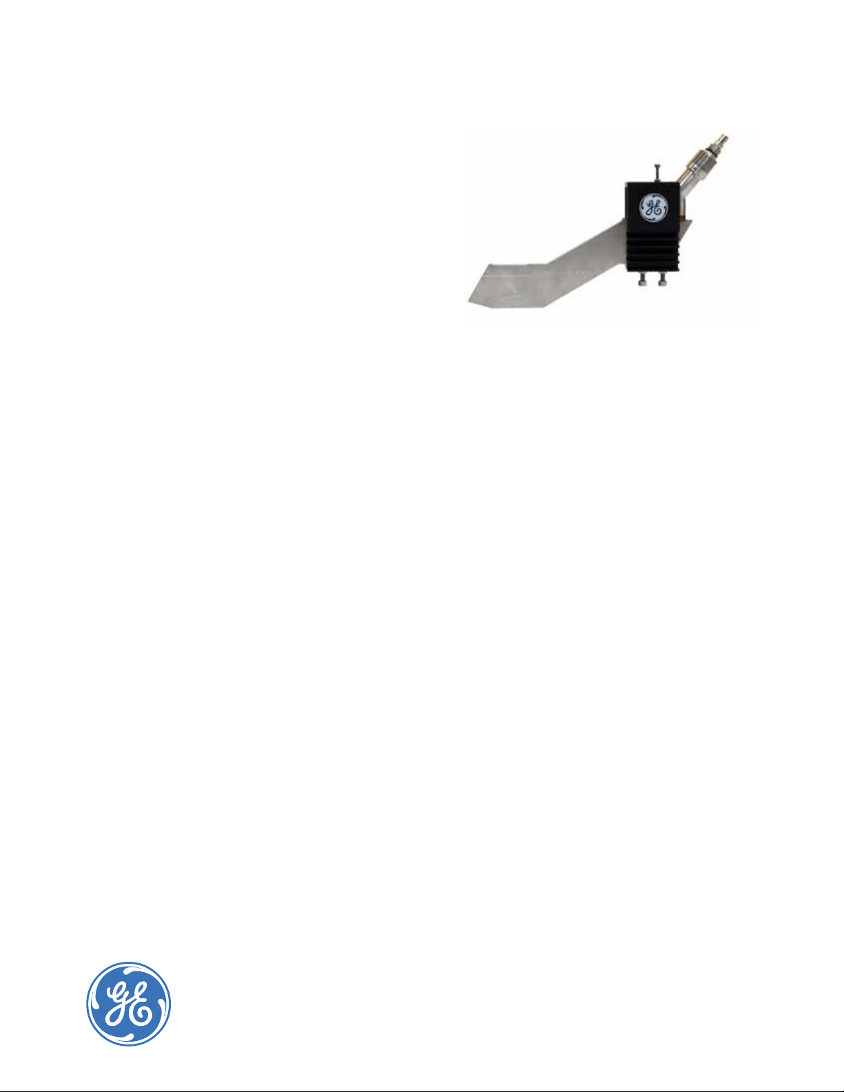
The C-ET Design
The C-ET system utilizes a solid waveguide that
resembles a thin ice hockey stick, along with
our C-RS transducers. The robust design is an
improvement to the original OKS buer system
released in the 1980s. It maximizes the signal-to-
noise ratio for a more accurate ow measurement
and maximizes the heat exchange away from
the C-RS transducer. With ultrasonic operating
frequencies of 0.5 and 1 MHz, the C-ET waveguide
transducer system can be used on a variety of
liquids, from superheated water and hot, heavy
hydrocarbons, to cryogenic liqueed natural gas.
The waveguide will keep the piezoelectric element
considerably within its operating temperature, thus
ensuring an indenite life for the transducer.
Choices for All Applications
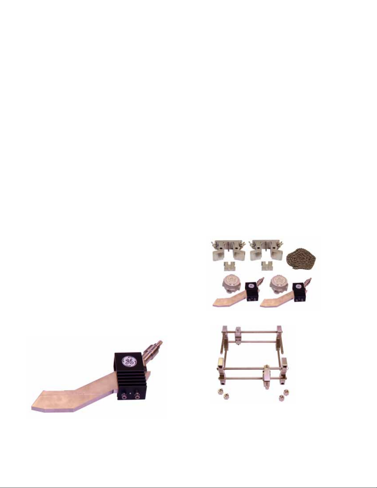
The C-ET transducer system can be used not only in
a variety of applications, but can also be installed in
numerous convenient ways.
For smaller sized pipes, use the GE stainless steel
V-style clamping xture to accurately align the
transducers. For larger sized pipes, the PI-style
stainless chain xture is used to provide a exible
mounting solution. With either xture, a solid couplant
is used to mount transducers to the pipe, minimizing
future maintenance.
Advanced Technology
C-ET Waveguide Systems
When combined with any of the DigitalFlow™
ultrasonic ow meters, the C-ET transducer system
takes advantage of GE’s patented Correlation
Transit-Time™ technique and advanced digital-
signal processing. The C-ET transducer system
and DigitalFlow ow meters provide the proven
technology and accuracy that have made GE a leader
in innovative instrumentation technology.
Chaining option
C-ET sensor
Clamping option
Page 3

C-ET Specications
Operation and Performance
Specications assume a fully developed ow
prole (typically 10 diameters upstream and 5
diameters downstream of straight pipe run) and
ow velocity greater than 0.3 m/s (1 ft/s).
Pipe Sizes
3 in to 24 in (80 to 600 mm) NB and larger
Pipe Wall Thickness
Up to 3 in (80 mm)
Flow Accuracy (Velocity)
• Pipe ID>6 in (150 mm): ±1% to 2% of reading
• Pipe ID<6 in (150 mm): ±2% to 5% of reading
Accuracy depends on pipe size and whether
measurement is one-path or two-path.
Accuracy to ±0.5% of reading may be
achievable with process calibration.
Clamp-on Ultrasonic Flow
Transducers
Temperature Range
Process: –200°C to 400°C (-328°F to 750°F)
Ambient: -40°C to 75°C (-40°F to 167°F)
Materials
Fixture: stainless steel
Waveguide: stainless steel
Transducer: stainless steel and plastic
Transducer Holder: coated aluminum
Certications (Integral C-RS Transducer)
• CSA certied (Class 1, Div. 1, Groups B, C, and D)
• ATEX certied (II 2 GD Eex md IIC T6 T=80°C)
Page 4

Ordering Information
X- X- X- X- X X- X-
C-ET Pair of high performance clamp-on transducers for extreme temperature applications consisting
of C-RS transducers, waveguide, mounting xture, and couplant. Maximum operating process
temperature of -200°C to 400°C (-328°F to 752°F)
05 0.5 MHz frequency C-RS transducers
10 1 MHz frequency C-RS transducers
00 No junction box
AX CSA certied, epoxy coated aluminum, junction box (Class 1, Div. 1, Groups B, C and D)
EX ATEX certied, epoxy coated aluminum, junction box (II 2 GD Eex md IIC T6 T=80°C)
EXSS ATEX certied, stainless steel, junction box (II 2GD Eex md IIC T6 T=80°C)
V4 V4 bracket clamping xture for pipes from 3-4 in (80 to 100 mm)
V8 V8 bracket clamping xture for pipes from 4-8 in (100 to 200 mm)
V12 V12 bracket clamping xture for pipes from 8-12 in (200 to 300 mm)
PIC PIC chain clamping xture for pipes from 8-24 in (200 to 600 mm)
<> <> Pipe Size
IN Pipe outer diameter - in
MM Pipe outer diameter - millimeters
12 Couplant #12 (Temperature range -20 to 400°C)
13 Couplant #13 (Temperature range -200 to 100°C)
14 Couplant #14 (Temperature range -20 to 400°C)
15 Couplant #15 (Temperature range -20 to 400°C)
0 Standard product
S Special
— — — — — — —
www.ge-mcs.com
920-567A
© 2011 General Electric Company. All Rights Reserved. Specications are subject to change without notice. GE is a registered trademark of General Electric Company. Other company or product
names mentioned in this document may be trademarks or registered trademarks of their respective companies, which are not aliated with GE.
 Loading...