

Page 1
AquaTrans™ AT600
User’s Manual
Flow
bhge.com
910-312 Rev. D
September 2017
Page 2

Page 3

AquaTrans™ AT600
Panametrics Ultrasonic Flow Meter for Liquids
User’s Manual
910-312 Rev. D
September 2017
bhge.com
© 2017 Baker Hughes, a GE company – All rights reserved.
Baker Hughes reserves the right to make changes in specifications and features shown herein, or discontinue the product
described at any time without notice or obligation. Contact your BHGE representative for the most current information. The
Baker Hughes logo is a trade mark of Baker Hughes, a GE company. The GE Monogram is a trademark of the General Electric
Company.
Page 4

[no content intended for this page]
Page 5

Contents
Product Registration . . . . . . . . . . . . . . . . . . . . . . . . . . . . . . . . . . . . . . . . . . . . . . . . . . . . . . . . . . . . . . . . . . . . . . . . . . . . . . . . . . . . . . . . . . . vii
Services . . . . . . . . . . . . . . . . . . . . . . . . . . . . . . . . . . . . . . . . . . . . . . . . . . . . . . . . . . . . . . . . . . . . . . . . . . . . . . . . . . . . . . . . . . . . . . . . . . . . . . . vii
Terms and Conditions. . . . . . . . . . . . . . . . . . . . . . . . . . . . . . . . . . . . . . . . . . . . . . . . . . . . . . . . . . . . . . . . . . . . . . . . . . . . . . . . . . . . . . . . . . vii
Typographical Conventions . . . . . . . . . . . . . . . . . . . . . . . . . . . . . . . . . . . . . . . . . . . . . . . . . . . . . . . . . . . . . . . . . . . . . . . . . . . . . . . . . . . . vii
Safety Issues . . . . . . . . . . . . . . . . . . . . . . . . . . . . . . . . . . . . . . . . . . . . . . . . . . . . . . . . . . . . . . . . . . . . . . . . . . . . . . . . . . . . . . . . . . . . . . . . . . vii
Auxiliary Equipment . . . . . . . . . . . . . . . . . . . . . . . . . . . . . . . . . . . . . . . . . . . . . . . . . . . . . . . . . . . . . . . . . . . . . . . . . . . . . . . . . . . . . . . . . . .viii
Environmental Compliance . . . . . . . . . . . . . . . . . . . . . . . . . . . . . . . . . . . . . . . . . . . . . . . . . . . . . . . . . . . . . . . . . . . . . . . . . . . . . . . . . . . . .ix
Chapter 1. General Installation Instructions
1.1 Introduction. . . . . . . . . . . . . . . . . . . . . . . . . . . . . . . . . . . . . . . . . . . . . . . . . . . . . . . . . . . . . . . . . . . . . . . . . . . . . . . . . . . . . . . . . . . . . . . 1
1.2 Theory of Operation . . . . . . . . . . . . . . . . . . . . . . . . . . . . . . . . . . . . . . . . . . . . . . . . . . . . . . . . . . . . . . . . . . . . . . . . . . . . . . . . . . . . . . . 2
1.3 Safety Guidelines. . . . . . . . . . . . . . . . . . . . . . . . . . . . . . . . . . . . . . . . . . . . . . . . . . . . . . . . . . . . . . . . . . . . . . . . . . . . . . . . . . . . . . . . . . 3
1.4 Unpacking the AT600 system. . . . . . . . . . . . . . . . . . . . . . . . . . . . . . . . . . . . . . . . . . . . . . . . . . . . . . . . . . . . . . . . . . . . . . . . . . . . . . 4
1.5 Installing the Electronics Enclosure . . . . . . . . . . . . . . . . . . . . . . . . . . . . . . . . . . . . . . . . . . . . . . . . . . . . . . . . . . . . . . . . . . . . . . . . 5
1.6 Calculating the Transducer Spacing . . . . . . . . . . . . . . . . . . . . . . . . . . . . . . . . . . . . . . . . . . . . . . . . . . . . . . . . . . . . . . . . . . . . . . . . 6
1.7 Choosing a Clamp-On Fixture/Transducer Location . . . . . . . . . . . . . . . . . . . . . . . . . . . . . . . . . . . . . . . . . . . . . . . . . . . . . . . . 7
1.8 Mounting the Clamp-on Fixture and Transducer System. . . . . . . . . . . . . . . . . . . . . . . . . . . . . . . . . . . . . . . . . . . . . . . . . . . . 8
Chapter 2. Clamp-On Fixture and Transducer Installation
2.1 Installing an AT600 Clamp-On Fixture and Transducer System. . . . . . . . . . . . . . . . . . . . . . . . . . . . . . . . . . . . . . . . . . . . .11
2.1.1 Transducer Spacing = 32 to 250 mm or 50 to 320 mm, Traverses = 2, Fixtures = 1 . . . . . . . . . . . . . . . . . 11
2.1.2 Transducer Spacing = 320 to 940 mm, Traverses = 2, Fixtures = 2 . . . . . . . . . . . . . . . . . . . . . . . . . . . . . . . . . 14
2.1.3 Transducer Spacing = 0 to 250 mm or 0 to 320 mm, Traverses = 1, Fixtures = 2 . . . . . . . . . . . . . . . . . . . .17
2.1.4 Transducer Spacing >320 mm, Traverses = 1, Fixtures = 2. . . . . . . . . . . . . . . . . . . . . . . . . . . . . . . . . . . . . . . . . 19
2.2 Installing a CF-ES Clamp-On Fixture and Transducer System . . . . . . . . . . . . . . . . . . . . . . . . . . . . . . . . . . . . . . . . . . . . . .20
2.3 Installing a General Clamping Fixture and Transducer System . . . . . . . . . . . . . . . . . . . . . . . . . . . . . . . . . . . . . . . . . . . . . 20
2.3.1 Installing C-RS or C-PT Transducers with an RG316 Cable. . . . . . . . . . . . . . . . . . . . . . . . . . . . . . . . . . . . . . . . . 20
2.3.2 Installing C-RS or C-PT Transducers with an RG62 Cable . . . . . . . . . . . . . . . . . . . . . . . . . . . . . . . . . . . . . . . . . . 21
Chapter 3. Wiring the AT600 Electronics
3.1 Wiring Diagram . . . . . . . . . . . . . . . . . . . . . . . . . . . . . . . . . . . . . . . . . . . . . . . . . . . . . . . . . . . . . . . . . . . . . . . . . . . . . . . . . . . . . . . . . .23
3.2 Wiring the Line Power . . . . . . . . . . . . . . . . . . . . . . . . . . . . . . . . . . . . . . . . . . . . . . . . . . . . . . . . . . . . . . . . . . . . . . . . . . . . . . . . . . . .25
3.3 Wiring the Transducers. . . . . . . . . . . . . . . . . . . . . . . . . . . . . . . . . . . . . . . . . . . . . . . . . . . . . . . . . . . . . . . . . . . . . . . . . . . . . . . . . . .26
3.4 Wiring the System Ground . . . . . . . . . . . . . . . . . . . . . . . . . . . . . . . . . . . . . . . . . . . . . . . . . . . . . . . . . . . . . . . . . . . . . . . . . . . . . . . 27
3.5 Wiring the Analog Output for HART Communication . . . . . . . . . . . . . . . . . . . . . . . . . . . . . . . . . . . . . . . . . . . . . . . . . . . . . . 27
3.6 Wiring the Modbus Communication . . . . . . . . . . . . . . . . . . . . . . . . . . . . . . . . . . . . . . . . . . . . . . . . . . . . . . . . . . . . . . . . . . . . . . 28
3.7 Wiring the Frequency/Totalizer/Alarm Output . . . . . . . . . . . . . . . . . . . . . . . . . . . . . . . . . . . . . . . . . . . . . . . . . . . . . . . . . . . . 29
3.8 Wiring the Gate Input . . . . . . . . . . . . . . . . . . . . . . . . . . . . . . . . . . . . . . . . . . . . . . . . . . . . . . . . . . . . . . . . . . . . . . . . . . . . . . . . . . . . 30
Chapter 4. Initial Setup and Programming
4.1 Introduction. . . . . . . . . . . . . . . . . . . . . . . . . . . . . . . . . . . . . . . . . . . . . . . . . . . . . . . . . . . . . . . . . . . . . . . . . . . . . . . . . . . . . . . . . . . . . . 31
4.2 AT600 Keypad Operation . . . . . . . . . . . . . . . . . . . . . . . . . . . . . . . . . . . . . . . . . . . . . . . . . . . . . . . . . . . . . . . . . . . . . . . . . . . . . . . . .32
4.3 Display Programming. . . . . . . . . . . . . . . . . . . . . . . . . . . . . . . . . . . . . . . . . . . . . . . . . . . . . . . . . . . . . . . . . . . . . . . . . . . . . . . . . . . . . 33
AquaTrans™ AT600 User’s Manual iii
Page 6

Contents
4.3.1 Changing the Display for One- or Two-Variable Screens . . . . . . . . . . . . . . . . . . . . . . . . . . . . . . . . . . . . . . . . . .33
4.3.2 Changing the Measurement Type for One- or Two-Variable Screens . . . . . . . . . . . . . . . . . . . . . . . . . . . . . . 34
4.3.3 Changing the Measurement Type or Units for the Totalizer Screens . . . . . . . . . . . . . . . . . . . . . . . . . . . . . . .35
4.3.4 Starting or Stopping the Totalizer Measurement. . . . . . . . . . . . . . . . . . . . . . . . . . . . . . . . . . . . . . . . . . . . . . . . . . 37
4.3.5 Resetting the Totalizer . . . . . . . . . . . . . . . . . . . . . . . . . . . . . . . . . . . . . . . . . . . . . . . . . . . . . . . . . . . . . . . . . . . . . . . . . . . 38
4.4 Entering the Main Menu . . . . . . . . . . . . . . . . . . . . . . . . . . . . . . . . . . . . . . . . . . . . . . . . . . . . . . . . . . . . . . . . . . . . . . . . . . . . . . . . . . 39
4.4.1 Display Format . . . . . . . . . . . . . . . . . . . . . . . . . . . . . . . . . . . . . . . . . . . . . . . . . . . . . . . . . . . . . . . . . . . . . . . . . . . . . . . . . . 39
4.4.2 Keypad Lockout . . . . . . . . . . . . . . . . . . . . . . . . . . . . . . . . . . . . . . . . . . . . . . . . . . . . . . . . . . . . . . . . . . . . . . . . . . . . . . . . . 40
4.4.3 Language. . . . . . . . . . . . . . . . . . . . . . . . . . . . . . . . . . . . . . . . . . . . . . . . . . . . . . . . . . . . . . . . . . . . . . . . . . . . . . . . . . . . . . . . 41
4.4.4 Program and Program Review Menus . . . . . . . . . . . . . . . . . . . . . . . . . . . . . . . . . . . . . . . . . . . . . . . . . . . . . . . . . . . . 41
4.5 User Preferences. . . . . . . . . . . . . . . . . . . . . . . . . . . . . . . . . . . . . . . . . . . . . . . . . . . . . . . . . . . . . . . . . . . . . . . . . . . . . . . . . . . . . . . . . 43
4.5.1 Setting . . . . . . . . . . . . . . . . . . . . . . . . . . . . . . . . . . . . . . . . . . . . . . . . . . . . . . . . . . . . . . . . . . . . . . . . . . . . . . . . . . . . . . . . . . 43
4.5.2 Units Setting . . . . . . . . . . . . . . . . . . . . . . . . . . . . . . . . . . . . . . . . . . . . . . . . . . . . . . . . . . . . . . . . . . . . . . . . . . . . . . . . . . . . 44
4.5.3 Density. . . . . . . . . . . . . . . . . . . . . . . . . . . . . . . . . . . . . . . . . . . . . . . . . . . . . . . . . . . . . . . . . . . . . . . . . . . . . . . . . . . . . . . . . . 45
4.5.4 Password. . . . . . . . . . . . . . . . . . . . . . . . . . . . . . . . . . . . . . . . . . . . . . . . . . . . . . . . . . . . . . . . . . . . . . . . . . . . . . . . . . . . . . . .46
4.5.5 Display . . . . . . . . . . . . . . . . . . . . . . . . . . . . . . . . . . . . . . . . . . . . . . . . . . . . . . . . . . . . . . . . . . . . . . . . . . . . . . . . . . . . . . . . . .46
4.6 Inputs/Outputs. . . . . . . . . . . . . . . . . . . . . . . . . . . . . . . . . . . . . . . . . . . . . . . . . . . . . . . . . . . . . . . . . . . . . . . . . . . . . . . . . . . . . . . . . . . 48
4.6.1 Programming the Analog Output Menu . . . . . . . . . . . . . . . . . . . . . . . . . . . . . . . . . . . . . . . . . . . . . . . . . . . . . . . . . . 48
4.6.2 Programming the Digital Output Menu . . . . . . . . . . . . . . . . . . . . . . . . . . . . . . . . . . . . . . . . . . . . . . . . . . . . . . . . . . . 51
4.6.3 Programming the Modbus/Service Port . . . . . . . . . . . . . . . . . . . . . . . . . . . . . . . . . . . . . . . . . . . . . . . . . . . . . . . . . . 61
4.6.4 Programming Digital Communications . . . . . . . . . . . . . . . . . . . . . . . . . . . . . . . . . . . . . . . . . . . . . . . . . . . . . . . . . . . 61
4.7 Sensor Setup. . . . . . . . . . . . . . . . . . . . . . . . . . . . . . . . . . . . . . . . . . . . . . . . . . . . . . . . . . . . . . . . . . . . . . . . . . . . . . . . . . . . . . . . . . . . . 66
4.7.1 Meter Setup . . . . . . . . . . . . . . . . . . . . . . . . . . . . . . . . . . . . . . . . . . . . . . . . . . . . . . . . . . . . . . . . . . . . . . . . . . . . . . . . . . . . . 67
4.7.2 Mounting Type. . . . . . . . . . . . . . . . . . . . . . . . . . . . . . . . . . . . . . . . . . . . . . . . . . . . . . . . . . . . . . . . . . . . . . . . . . . . . . . . . . . 68
4.7.3 Programming the Pipe Menu when Wetted selected . . . . . . . . . . . . . . . . . . . . . . . . . . . . . . . . . . . . . . . . . . . . .69
4.7.4 Programming the Pipe Menu when Clamp-on selected . . . . . . . . . . . . . . . . . . . . . . . . . . . . . . . . . . . . . . . . . . . 70
4.7.5 Programming the Transducer when Clamp-on selected. . . . . . . . . . . . . . . . . . . . . . . . . . . . . . . . . . . . . . . . . . . 74
4.7.6 Programming the Transducer when Wetted selected . . . . . . . . . . . . . . . . . . . . . . . . . . . . . . . . . . . . . . . . . . . . . 80
4.7.7 Programming the Number of Traverses . . . . . . . . . . . . . . . . . . . . . . . . . . . . . . . . . . . . . . . . . . . . . . . . . . . . . . . . . .83
4.7.8 Programming the Fluid Type . . . . . . . . . . . . . . . . . . . . . . . . . . . . . . . . . . . . . . . . . . . . . . . . . . . . . . . . . . . . . . . . . . . . . 84
4.7.9 Programming the Fluid Temperature . . . . . . . . . . . . . . . . . . . . . . . . . . . . . . . . . . . . . . . . . . . . . . . . . . . . . . . . . . . . . 85
4.7.10 Calculating the Path when Clamp-on selected . . . . . . . . . . . . . . . . . . . . . . . . . . . . . . . . . . . . . . . . . . . . . . . . . . .86
4.7.11 Enter the Path when Wetted selected . . . . . . . . . . . . . . . . . . . . . . . . . . . . . . . . . . . . . . . . . . . . . . . . . . . . . . . . . . . 87
Chapter 5. Error Codes and Troubleshooting
5.1 Error Display in the User Interface . . . . . . . . . . . . . . . . . . . . . . . . . . . . . . . . . . . . . . . . . . . . . . . . . . . . . . . . . . . . . . . . . . . . . . . . 89
5.1.1 Error Header . . . . . . . . . . . . . . . . . . . . . . . . . . . . . . . . . . . . . . . . . . . . . . . . . . . . . . . . . . . . . . . . . . . . . . . . . . . . . . . . . . . .89
5.1.2 Flow Error String. . . . . . . . . . . . . . . . . . . . . . . . . . . . . . . . . . . . . . . . . . . . . . . . . . . . . . . . . . . . . . . . . . . . . . . . . . . . . . . . . 89
5.2 Diagnostics . . . . . . . . . . . . . . . . . . . . . . . . . . . . . . . . . . . . . . . . . . . . . . . . . . . . . . . . . . . . . . . . . . . . . . . . . . . . . . . . . . . . . . . . . . . . . . 93
5.2.1 Introduction . . . . . . . . . . . . . . . . . . . . . . . . . . . . . . . . . . . . . . . . . . . . . . . . . . . . . . . . . . . . . . . . . . . . . . . . . . . . . . . . . . . . .93
5.2.2 Flowcell Problems . . . . . . . . . . . . . . . . . . . . . . . . . . . . . . . . . . . . . . . . . . . . . . . . . . . . . . . . . . . . . . . . . . . . . . . . . . . . . . .93
iv AquaTrans™ AT600 User’s Manual
Page 7

Contents
Chapter 6. Communication
6.1 MODBUS . . . . . . . . . . . . . . . . . . . . . . . . . . . . . . . . . . . . . . . . . . . . . . . . . . . . . . . . . . . . . . . . . . . . . . . . . . . . . . . . . . . . . . . . . . . . . . . . .97
6.1.1 Introduction . . . . . . . . . . . . . . . . . . . . . . . . . . . . . . . . . . . . . . . . . . . . . . . . . . . . . . . . . . . . . . . . . . . . . . . . . . . . . . . . . . . . .97
6.1.2 MODBUS Register Map . . . . . . . . . . . . . . . . . . . . . . . . . . . . . . . . . . . . . . . . . . . . . . . . . . . . . . . . . . . . . . . . . . . . . . . . . . 97
6.2 HART. . . . . . . . . . . . . . . . . . . . . . . . . . . . . . . . . . . . . . . . . . . . . . . . . . . . . . . . . . . . . . . . . . . . . . . . . . . . . . . . . . . . . . . . . . . . . . . . . . . .105
6.2.1 Device Identification. . . . . . . . . . . . . . . . . . . . . . . . . . . . . . . . . . . . . . . . . . . . . . . . . . . . . . . . . . . . . . . . . . . . . . . . . . . .105
6.2.2 Commands . . . . . . . . . . . . . . . . . . . . . . . . . . . . . . . . . . . . . . . . . . . . . . . . . . . . . . . . . . . . . . . . . . . . . . . . . . . . . . . . . . . . .105
6.3 Additional Device Status . . . . . . . . . . . . . . . . . . . . . . . . . . . . . . . . . . . . . . . . . . . . . . . . . . . . . . . . . . . . . . . . . . . . . . . . . . . . . . . .166
6.4 Device Variables. . . . . . . . . . . . . . . . . . . . . . . . . . . . . . . . . . . . . . . . . . . . . . . . . . . . . . . . . . . . . . . . . . . . . . . . . . . . . . . . . . . . . . . . .167
6.5 HART Engineering Units . . . . . . . . . . . . . . . . . . . . . . . . . . . . . . . . . . . . . . . . . . . . . . . . . . . . . . . . . . . . . . . . . . . . . . . . . . . . . . . . .168
Appendix A. Specifications
A.1 Overall Operation and Performance . . . . . . . . . . . . . . . . . . . . . . . . . . . . . . . . . . . . . . . . . . . . . . . . . . . . . . . . . . . . . . . . . . . . .173
A.2 Electronics . . . . . . . . . . . . . . . . . . . . . . . . . . . . . . . . . . . . . . . . . . . . . . . . . . . . . . . . . . . . . . . . . . . . . . . . . . . . . . . . . . . . . . . . . . . . . .174
A.3 Clamp-On Ultrasonic Flow Transducers. . . . . . . . . . . . . . . . . . . . . . . . . . . . . . . . . . . . . . . . . . . . . . . . . . . . . . . . . . . . . . . . . .175
A.4 General . . . . . . . . . . . . . . . . . . . . . . . . . . . . . . . . . . . . . . . . . . . . . . . . . . . . . . . . . . . . . . . . . . . . . . . . . . . . . . . . . . . . . . . . . . . . . . . . .177
A.4.1 Wiring Cable Specifications and Requirements . . . . . . . . . . . . . . . . . . . . . . . . . . . . . . . . . . . . . . . . . . . . . . . . . .177
A.4.2 Cable Fixing Requirement and Gland Torque . . . . . . . . . . . . . . . . . . . . . . . . . . . . . . . . . . . . . . . . . . . . . . . . . . . .177
A.4.3 Display Languages. . . . . . . . . . . . . . . . . . . . . . . . . . . . . . . . . . . . . . . . . . . . . . . . . . . . . . . . . . . . . . . . . . . . . . . . . . . . . .177
A.4.4 Product Models. . . . . . . . . . . . . . . . . . . . . . . . . . . . . . . . . . . . . . . . . . . . . . . . . . . . . . . . . . . . . . . . . . . . . . . . . . . . . . . . .177
Appendix B. Data Records
B.1 Service Record . . . . . . . . . . . . . . . . . . . . . . . . . . . . . . . . . . . . . . . . . . . . . . . . . . . . . . . . . . . . . . . . . . . . . . . . . . . . . . . . . . . . . . . . . .179
B.2 Data Entry . . . . . . . . . . . . . . . . . . . . . . . . . . . . . . . . . . . . . . . . . . . . . . . . . . . . . . . . . . . . . . . . . . . . . . . . . . . . . . . . . . . . . . . . . . . . . .179
B.3 Initial Settings. . . . . . . . . . . . . . . . . . . . . . . . . . . . . . . . . . . . . . . . . . . . . . . . . . . . . . . . . . . . . . . . . . . . . . . . . . . . . . . . . . . . . . . . . . .180
B.4 Diagnostic Parameters . . . . . . . . . . . . . . . . . . . . . . . . . . . . . . . . . . . . . . . . . . . . . . . . . . . . . . . . . . . . . . . . . . . . . . . . . . . . . . . . . .181
Appendix C. Updating the Firmware in the Field
C.1 Introduction. . . . . . . . . . . . . . . . . . . . . . . . . . . . . . . . . . . . . . . . . . . . . . . . . . . . . . . . . . . . . . . . . . . . . . . . . . . . . . . . . . . . . . . . . . . . .183
C.1.1 System Requirements . . . . . . . . . . . . . . . . . . . . . . . . . . . . . . . . . . . . . . . . . . . . . . . . . . . . . . . . . . . . . . . . . . . . . . . . . .183
C.1.2 Preparation. . . . . . . . . . . . . . . . . . . . . . . . . . . . . . . . . . . . . . . . . . . . . . . . . . . . . . . . . . . . . . . . . . . . . . . . . . . . . . . . . . . . .183
C.2 Performing the Firmware Update . . . . . . . . . . . . . . . . . . . . . . . . . . . . . . . . . . . . . . . . . . . . . . . . . . . . . . . . . . . . . . . . . . . . . . . .184
C.2.1 Check the Current Firmware Version. . . . . . . . . . . . . . . . . . . . . . . . . . . . . . . . . . . . . . . . . . . . . . . . . . . . . . . . . . . .184
C.2.2 Update Steps . . . . . . . . . . . . . . . . . . . . . . . . . . . . . . . . . . . . . . . . . . . . . . . . . . . . . . . . . . . . . . . . . . . . . . . . . . . . . . . . . . .184
C.3 Clearing an S2 Warning. . . . . . . . . . . . . . . . . . . . . . . . . . . . . . . . . . . . . . . . . . . . . . . . . . . . . . . . . . . . . . . . . . . . . . . . . . . . . . . . . .186
C.4 Support . . . . . . . . . . . . . . . . . . . . . . . . . . . . . . . . . . . . . . . . . . . . . . . . . . . . . . . . . . . . . . . . . . . . . . . . . . . . . . . . . . . . . . . . . . . . . . . . .186
Appendix D. Menu Maps
D.1 The Display Measurement Menu . . . . . . . . . . . . . . . . . . . . . . . . . . . . . . . . . . . . . . . . . . . . . . . . . . . . . . . . . . . . . . . . . . . . . . . . .187
D.2 The Main Menu. . . . . . . . . . . . . . . . . . . . . . . . . . . . . . . . . . . . . . . . . . . . . . . . . . . . . . . . . . . . . . . . . . . . . . . . . . . . . . . . . . . . . . . . . .188
D.3 The Main Menu > User Preferences Menu . . . . . . . . . . . . . . . . . . . . . . . . . . . . . . . . . . . . . . . . . . . . . . . . . . . . . . . . . . . . . . . .189
D.4 The Main Menu > Inputs/Outputs Menu. . . . . . . . . . . . . . . . . . . . . . . . . . . . . . . . . . . . . . . . . . . . . . . . . . . . . . . . . . . . . . . . . .190
D.5 The Main Menu > Sensor Setup Menu. . . . . . . . . . . . . . . . . . . . . . . . . . . . . . . . . . . . . . . . . . . . . . . . . . . . . . . . . . . . . . . . . . . .191
AquaTrans™ AT600 User’s Manual v
Page 8

Contents
D.6 The Main Menu > Calibration Menu . . . . . . . . . . . . . . . . . . . . . . . . . . . . . . . . . . . . . . . . . . . . . . . . . . . . . . . . . . . . . . . . . . . . . .192
D.7 The Main Menu > Advanced Menu . . . . . . . . . . . . . . . . . . . . . . . . . . . . . . . . . . . . . . . . . . . . . . . . . . . . . . . . . . . . . . . . . . . . . . .193
D.8 The Main Menu > Factory Menu. . . . . . . . . . . . . . . . . . . . . . . . . . . . . . . . . . . . . . . . . . . . . . . . . . . . . . . . . . . . . . . . . . . . . . . . . .194
[no content intended for this page]
vi AquaTrans™ AT600 User’s Manual
Page 9
Preface
Product Registration
Thank you for purchasing your AquaTrans™ AT600 from Baker Hughes, a GE Company. Please register your
product at www.gemeasurement.com/productregistration
software/firmware upgrades, product information and special promotions.
for product support such as the latest
Services
BHGE provides customers with an experienced staff of customer support personnel ready to respond to
technical inquiries, as well as other remote and on-site support needs. To complement our broad portfolio of
industry-leading solutions, we offer several types of flexible and scalable support services including:
Training, Product Repairs, Extended Warranties, Service Agreements and more. Please visit
www.gemeasurement.com/services
for more details.
Terms and Conditions
Sales Terms and Conditions for your recent purchase of a BHGE product, including the applicable product
Warranty, can be found on our website at the following link:
www.gemeasurement.com/sales-terms-and-conditions
Typographical Conventions
Note: These paragraphs provide information that provides a deeper understanding of the situation, but is not
essential to the proper completion of the instructions.
IMPORTANT: These paragraphs provide information that emphasizes instructions that are essential to proper
setup of the equipment. Failure to follow these instructions carefully may cause unreliable
performance.
CAUTION! This symbol indicates a risk of potential minor personal injury and/or severe damage to
the equipment, unless these instructions are followed carefully.
WARNING! This symbol indicates a risk of potential serious personal injury, unless these
instructions are followed carefully.
Safety Issues
WARNING! It is the responsibility of the user to make sure all local, county, state and national
codes, regulations, rules and laws related to safety and safe operating conditions are met for each
installation.
Attention European Customers! To meet CE Marking requirements for all units intended for use in
the EU, all electrical cables must be installed as described in this manual.
AquaTrans™ AT600 User’s Manual vii
Page 10
Preface
Auxiliary Equipment
Local Safety Standards
The user must make sure that he operates all auxiliary equipment in accordance with local codes, standards,
regulations, or laws applicable to safety.
Working Area
WARNING! Auxiliary equipment may have both manual and automatic modes of operation. As
equipment can move suddenly and without warning, do not enter the work cell of this equipment
during automatic operation, and do not enter the work envelope of this equipment during manual
operation. If you do, serious injury can result.
WARNING! Make sure that power to the auxiliary equipment is turned OFF and locked out before
you perform maintenance procedures on this equipment.
Qualification of Personnel
Make sure that all personnel have manufacturer-approved training applicable to the auxiliary equipment.
Personal Safety Equipment
Make sure that operators and maintenance personnel have all safety equipment applicable to the auxiliary
equipment. Examples include safety glasses, protective headgear, safety shoes, etc.
Unauthorized Operation
Make sure that unauthorized personnel cannot gain access to the operation of the equipment.
viii AquaTrans™ AT600 User’s Manual
Page 11

Preface
Environmental Compliance
RoHS
The AquaTrans™ AT600 fully complies with RoHS regulations (Directive 2011/65/EU).
Waste Electrical and Electronic Equipment (WEEE) Directive
BHGE is an active participant in Europe’s Waste Electrical and Electronic Equipment (WEEE) take-back
initiative (Directive 2012/19/EU).
The equipment that you bought has required the extraction and use of natural resources for its production. It
may contain hazardous substances that could impact health and the environment.
In order to avoid the dissemination of those substances in our environment and to diminish the pressure on
the natural resources, we encourage you to use the appropriate take-back systems. Those systems will reuse
or recycle most of the materials of your end life equipment in a sound way.
The crossed-out wheeled bin symbol invites you to use those systems.
If you need more information on the collection, reuse and recycling systems, please contact your local or
regional waste administration.
Please visit http://www.gemeasurement.com/environmental-health-safety-ehs
more information about this initiative.
for take-back instructions and
AquaTrans™ AT600 User’s Manual ix
Page 12

Preface
[no content intended for this page]
x AquaTrans™ AT600 User’s Manual
Page 13
Chapter 1. General Installation Instructions
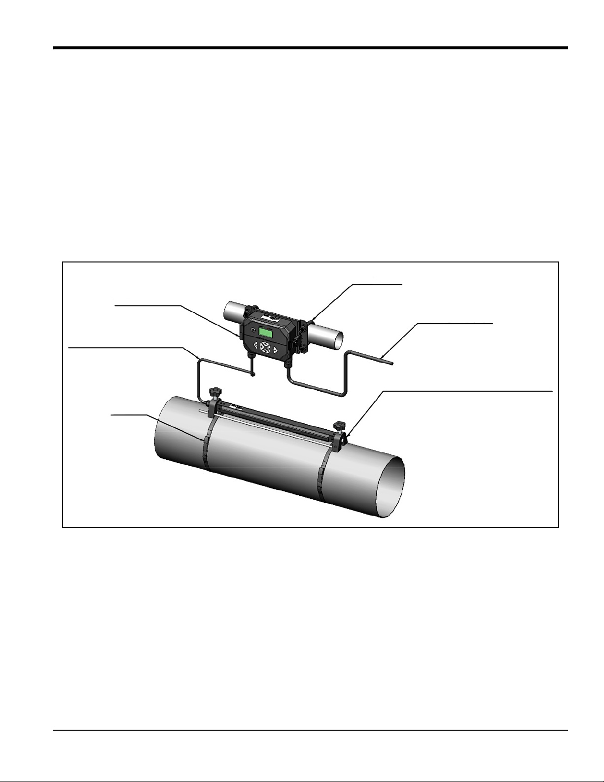
Electronics
Transducer Cable
Strap
U-Bolt
Power Cable
Fixture
With Transducer Installed
Chapter 1. General Installation Instructions
1.1 Introduction
Thank you for purchasing the AT600 ultrasonic flow meter. The AT600 is a clamp-on ultrasonic flow meter
for the measurement of liquid products. It is designed for the industrial applications, including water,
wastewater, steel, campus energy, and others. The AT600 utilizes a new electronics platform and industrial
design to make it extremely simple to install and use in the field.
• So easy to use, it practically installs itself
The AT600 consists of the new AT600 electronics, a metal enclosure, the field proven AT transducer system,
and a clamp-on transducer fixture (see Figure 1 below).
AquaTrans™ AT600 User’s Manual 1
Figure 1: Typical AT600 System Mounted on a Pipe
Page 14
Chapter 1. General Installation Instructions
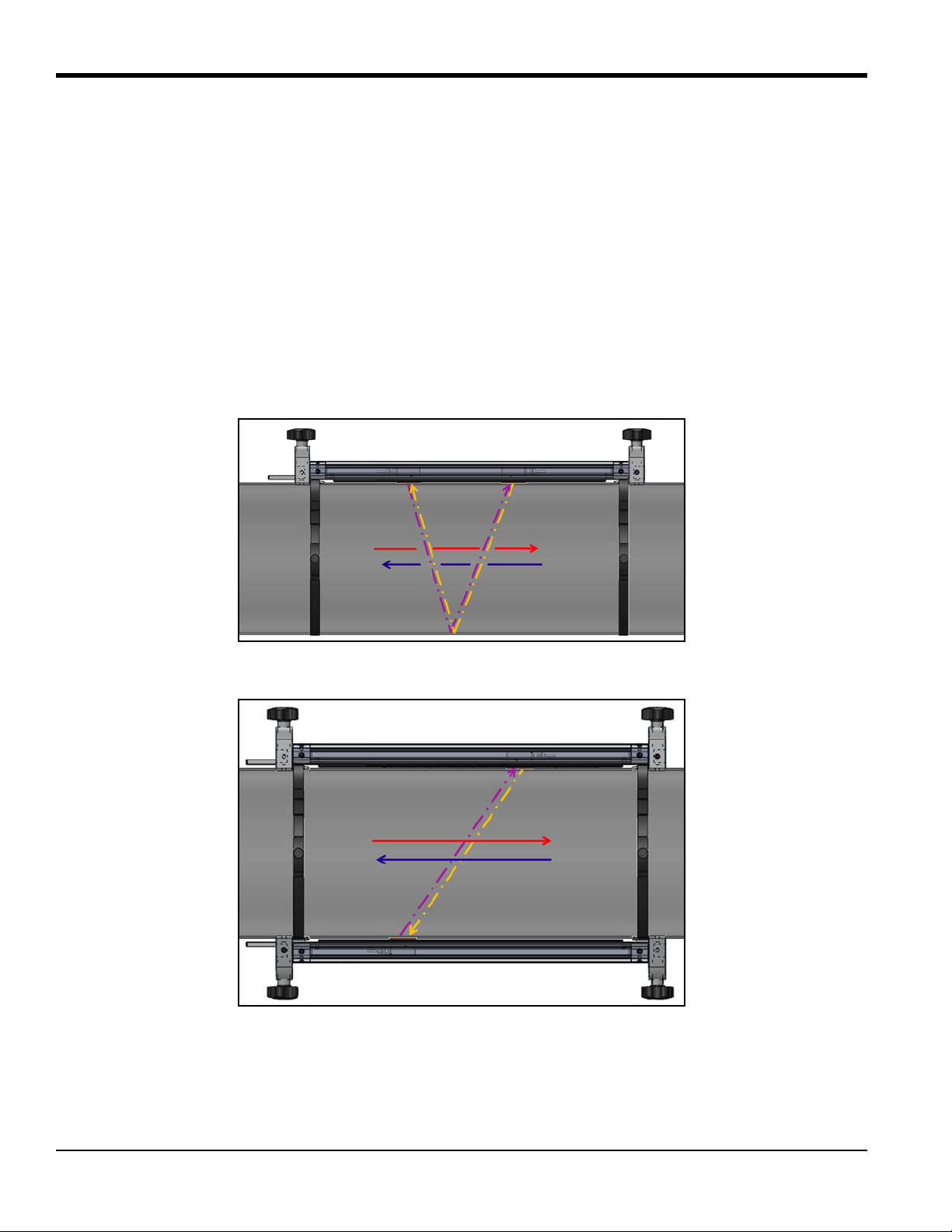
1.2 Theory of Operation
The AT600 flow meter uses a procedure called Transit-Time Flow Measurement. In this method, two
transducers, which are in acoustic communication with each other, serve as both ultrasonic signal
generators and receivers. That is, the second transducer can receive ultrasonic signals transmitted by the
first transducer and vice versa.
In operation, each transducer functions as a transmitter, generating a certain number of acoustic pulses, and
then as a receiver for an identical number of pulses (see Figure 2 and Figure 3 below). The time interval
between transmission and reception of the ultrasonic signals is measured in both directions. When the
liquid in the pipe is not flowing, the transit-time downstream equals the transit-time upstream. However,
when the liquid is flowing, the transit-time downstream is less than the transit-time upstream. The
difference between the downstream and upstream transit times is proportional to the velocity of the flowing
liquid and its sign indicates the direction of flow.
Figure 2: Flow and Transducer Paths (Two Traverses)
Figure 3: Flow and Transducer Paths (One Traverse)
2 AquaTrans™ AT600 User’s Manual
Page 15
Chapter 1. General Installation Instructions
1.3 Safety Guidelines
To ensure safe and reliable operation of the AT600, the system must be installed in accordance with the
guidelines discussed in this manual. This chapter includes the following topics:
• “Unpacking the AT600 system” on page 4
• “Installing the Electronics Enclosure” on page 5
• “Choosing a Clamp-On Fixture/Transducer Location” on page 7
• “Mounting the Clamp-on Fixture and Transducer System” on page 8
WARNING! The AT 600 flow transmitter can measure the flow rate of many fluids, some of which
are potentially hazardous. The importance of proper safety practices cannot be overemphasized.
WARNING! Be sure to follow all applicable local safety codes and regulations for installing electrical
equipment and working with hazardous fluids or flow conditions. Consult company safety personnel
or local safety authorities to verify the safety of any procedure or practice.
ATTENTION EUROPEAN CUSTOMERS! To meet CE Marking and UL Marking requirements, all cables
must be installed as described in “Wiring Cable Specifications and Requirements” on page 177.
AquaTrans™ AT600 User’s Manual 3
Page 16
Chapter 1. General Installation Instructions
1.4 Unpacking the AT600 system
Before removing the AT600 system from the crate, please inspect the flow meter. Before discarding any of
the packing materials, account for all components and documentation listed on the packing slip. The
discarding of an important item along with the packing materials is all too common. If anything is missing
or damaged, contact BHGE Customer Care immediately for assistance.
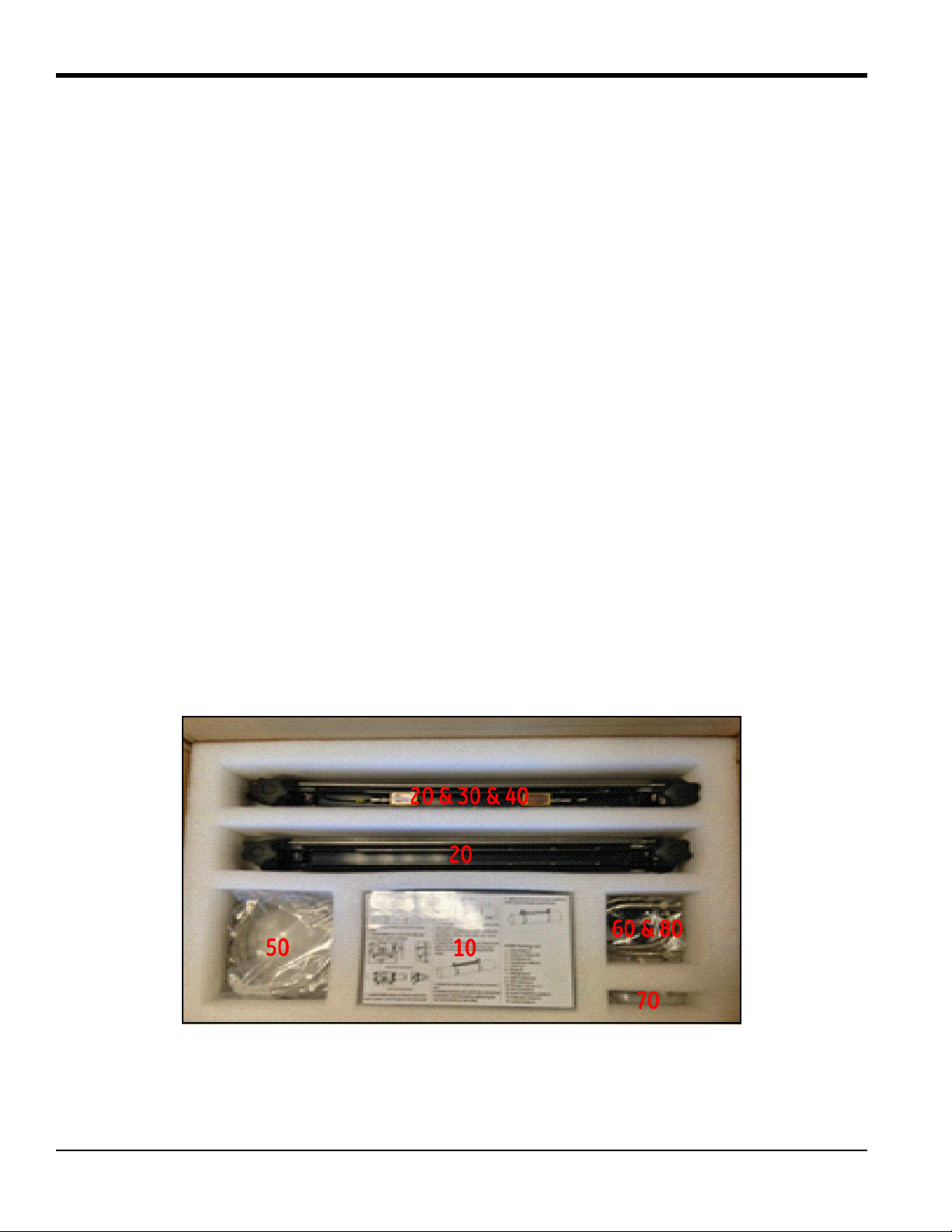
Please note that the AT600 system (see Figure 4 below) is available in a variety of configurations to meet your
needs, so the packing list will vary for each system. As an example, a typical packing list is:
1. One AT600 electronics enclosure
2. Two clamp-on fixtures
3. Two transducers (installed in one of the two clamp-on fixtures)
4. One transducer cable (installed on fixture with transducers)
5. Two clamp-on fixture mounting straps for each fixture
6. Two “U” bolts for pipe mounting of the AT600 electronics enclosure
7. One USB flash drive with user’s manual and calibration sheet
8. One inner hexagon spanner
9. Three M16 cable glands (installed on the AT600 electronics enclosure)
10. Two pieces of Solid Couplant
11. Quick installation guide
12. Calibration Sheet
13. Cabling tools
Figure 4: Typical AT600 Shipping Container
4 AquaTrans™ AT600 User’s Manual
Page 17
Chapter 1. General Installation Instructions
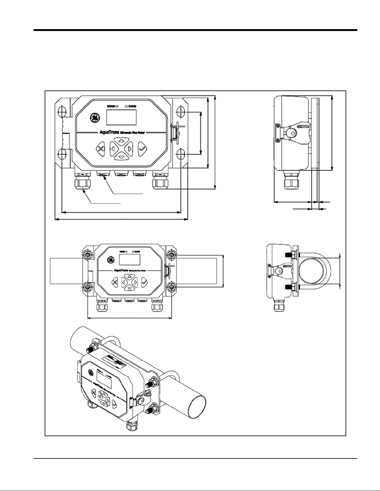
Weight is about 1.5 kg
Pipe Mount
Wall Mount
for the whole meter Assembly
M16 GLAND x3
202
13
3
63.50
128
120
160
72.50
M20 GLAND x2
202
226
2 Inch Pipe
72.50
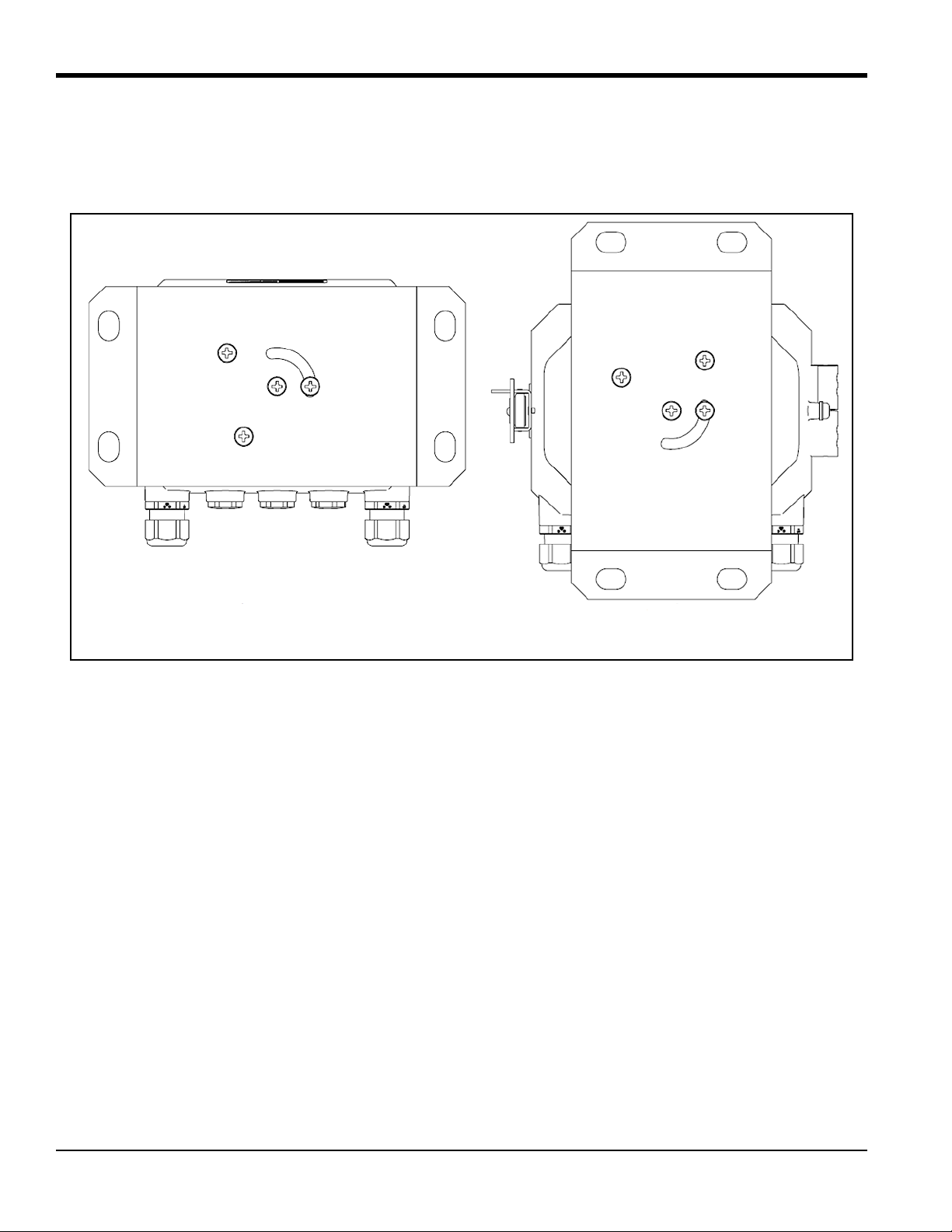
1.5 Installing the Electronics Enclosure
The AT600 electronics is housed in a powder-coated, aluminum, NEMA type 4X/IP67 enclosure suitable for
indoor or outdoor use. See Figure 5 below for the mounting dimensions and weight of the AT600 electronics
enclosure.
Figure 5: Mounting the AT600 Electronics Enclosure
AquaTrans™ AT600 User’s Manual 5
Page 18
Chapter 1. General Installation Instructions
Horizontal
Vertical
1.5 Installing the Electronics Enclosure (cont.)
The installation base of AT600 electronics enclosure can be rotated 90° to keep a horizontal view of the user
interface in any mounting orientation. See Figure 6 below for drawings of the AT600 mounting base.
Figure 6: The AT600 Mounting Base
1.6 Calculating the Transducer Spacing
Before installing the clamp-on fixture(s) and transducers, you must program the AT600 to calculate the
required transducer spacing for your planned installation. To accomplish this task, go to “Sensor Setup” on
page 66 and follow the instructions in that section. After obtaining the required transducer spacing value,
return here and continue to the next section.
6 AquaTrans™ AT600 User’s Manual
Page 19
Chapter 1. General Installation Instructions
Flow Direction
D
DOWNSTREAM
UPSTREAM
10 X D (in.)
5 X D (min)
Good
Good
Good
Bad
Bad
Flow
Flow
Flow
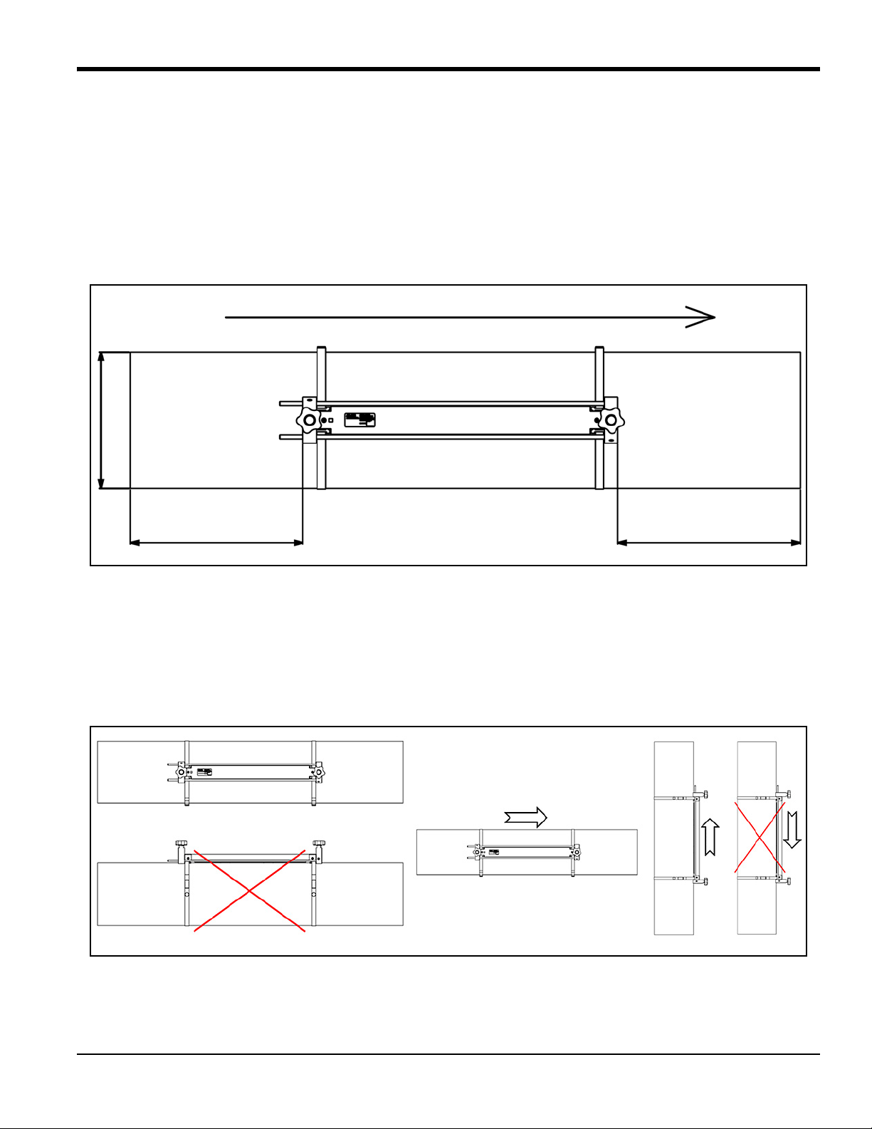
1.7 Choosing a Clamp-On Fixture/Transducer Location
For a given fluid and pipe, the accuracy of AT600 depends on the location and alignment of the transducers.
In addition to accessibility, when choosing a transducer location, follow these guidelines:
• Position the clamp-on fixture(s) and transducer system so that there are at least 10 pipe diameters of
straight, undisturbed flow upstream and 5 pipe diameters of straight, undisturbed flow downstream
from the measurement point (see Figure 7 below). Undisturbed flow means avoiding sources of
turbulence in the fluid such as valves, flanges, expansion joints, elbows, swirl, and cavitation.
Figure 7: AT600 Clamp-On Fixture/Transducer Location
• Locate the transducers on a common axial plane along the pipe (see Figure 8 below). The transducers
should be mounted on the side of the pipe, rather than the top or bottom, because the top of the pipe
tends to accumulate gases and the bottom tends to accumulate sediment. Either condition may cause
excessive attenuation of the ultrasonic signal. There is no similar restriction with vertical pipes, as
long as the flow direction is upward to prevent free falling of the fluid in a partially filled pipe.
Figure 8: Good and Bad Transducer Locations
AquaTrans™ AT600 User’s Manual 7
Page 20

Chapter 1. General Installation Instructions
1.8 Mounting the Clamp-on Fixture and Transducer System
The AT600 transducer system includes one or two clamp-on fixtures, two transducers and one transducer
cable. One clamp-on fixture is shipped with both transducers installed and the transducer cable connected
to the transducers. This fixture is the default setup for most applications. If a second fixture has been
ordered, it is shipped empty.
Transducers available for use with the AT600 flow meter are listed in Table 1 below.
Table 1: Available Transducers
Model Frequency Fixture Pipe Sizes
AT6 2, 1, 0.5 MHz AT600 2 in. (50 mm)
1
CF-LP
C-RS
C-PT
1
2
2
UTXDR
1
Go directly to: “Installing a CF-ES Clamp-On Fixture and Transducer System” on page 20.
4 MHz CF-ES 0.5-2 in. (15-50 mm)
4 MHz SPCF 0.5-8 in. (15-200 mm)
1, 0.5 MHz GCF 2 in. (50 mm)
2, 1, 0.5 MHz GCF 2 in. (50 mm)
2
Go directly to: “Installing a General Clamping Fixture and Transducer System” on page 20.
The AT600 clamp-on fixture and AT6 transducer system can be installed on pipe sizes 2 in. (50 mm). For
optimum performance in any specific application, either a two-traverse or one-traverse installation can be
chosen. Because the maximum pipe size for a single clamp-on fixture is 250 mm for 2 MHz transducers or
320 mm for 1 MHz and 0.5 MHz transducers, the detailed installation requirements differ based on the
calculated transducer spacing and the chosen number of traverses. Refer to Table 2 below to find the
parameters for your specific configuration.
Table 2: AT600 Clamp-On Fixture Installation
Pipe Size Range
mm inches
Transducer
Frequency (MHz)
Number of
Traverses
Transducer Spacing
(mm)
Number of
Fixtures
50 to 100 2 to 4 2 4 32 to 250 1
100 to 150 4 to 6 2 2 32 to 250 1
50 to 150 2 to 6 2 1 0 to 250 2
100 to 300 4 to 12 1 2 50 to 320 1
300 to 600 12 to 24 1 2 320 to 940 2
600 to 1500 24 to 60 1 1 >320 2
200 to 300 8 to 12 0.5 2 50 to 320 1
300 to 900 12 to 36 0.5 2 320 to 940 2
>900 >36 0.5 1 >320 2
IMPORTANT: See “Sensor Setup” on page 66 to calculate the required transducer spacing. A two traverse
installation is recommended for most applications.
IMPORTANT: If there is any type of coating or protective layer on the outer pipe surface, it must be removed at
the locations where the transducers and couplant contact the pipe surface.
8 AquaTrans™ AT600 User’s Manual
Page 21

Chapter 1. General Installation Instructions
1.8 Mounting the Clamp-on Fixture and Transducer System (cont.)
From the information on the previous page and the documentation included with your AT600 flow meter
system, you should already know the following details about your installation:
• Pipe Size
• Transducer Model
• Transducer Frequency
• Number of Traverses
• Calculated Transducer Spacing
• Number of Clamp-On Fixtures
Based on the known information, proceed directly to one of the following sections in the next chapter for
instructions on installing your AT600 clamp-on fixture(s) and transducers on the pipe:
Note: See the flowchart in Figure 9 on page 10 to assist in choosing the appropriate instructions for your
specific configuration.
• “Transducer Spacing = 32 to 250 mm or 50 to 320 mm, Traverses = 2, Fixtures = 1” on page 11
• “Transducer Spacing = 320 to 940 mm, Traverses = 2, Fixtures = 2” on page 14
• “Transducer Spacing = 0 to 250 mm or 0 to 320 mm, Traverses = 1, Fixtures = 2” on page 17
• “Transducer Spacing >320 mm, Traverses = 1, Fixtures = 2” on page 19
AquaTrans™ AT600 User’s Manual 9
Page 22
Chapter 1. General Installation Instructions
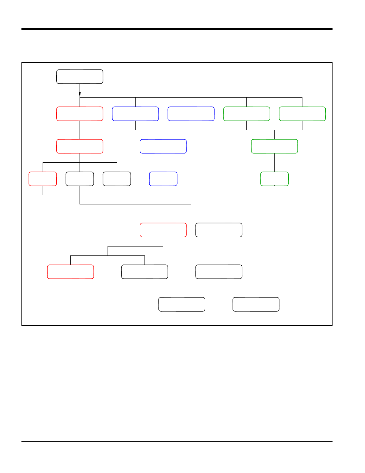
AT6 Trans. C-RS Trans. C-PT Trans.
UTXDR Trans.
CF-LP Trans.
2 MHz 1 MHz
0.5 MHz
2 Traverses 1 Traverse
AT600 Fixture CF-ES Fixture GCF Fixture
[Section 2.2 on page 19] [Section 2.3 on page 19]
START HERE
4 MHz 4 MHz
Note: The red boxes are the recommended configuration, which works for most applications.
1 Fixture 2 Fixtures 2 Fixtures
[Section 2.1.1 on page 11] [Section 2.1.2 on page 14]
Spacing to 320 Spacing >320
[Section 2.1.3 on page 16] [Section 2.1.4 on page 18]
1.8 Mounting the Clamp-on Fixture and Transducer System (cont.)
Figure 9: Flowchart to Transducer Installation Instructions
10 AquaTrans™ AT600 User’s Manual
Page 23
Chapter 2. Clamp-On Fixture and Transducer Installation
Move
Align
Screw Tighten
Chapter 2. Clamp-On Fixture and Transducer Installation
2.1 Installing an AT600 Clamp-On Fixture and Transducer System
The instructions in this section are for installations using the AT600 clamp-on fixture only. For installations
using other clamp-on fixtures, see “Installing a CF-ES Clamp-On Fixture and Transducer System” on page 20
or “Installing a General Clamping Fixture and Transducer System” on page 20.
2.1.1 Transducer Spacing = 32 to 250 mm or 50 to 320 mm, Traverses = 2, Fixtures = 1
Note: A two traverse installation with one clamp-on fixture is the standard AT600 configuration.
When the required transducer spacing is 32 to 250 mm for a 2 MHz transducer or 50 to 320 mm for a 1 MHz
or
0.5 MHz transducer, one clamp-on fixture is needed for a dual traverse installation. Proceed as follows:
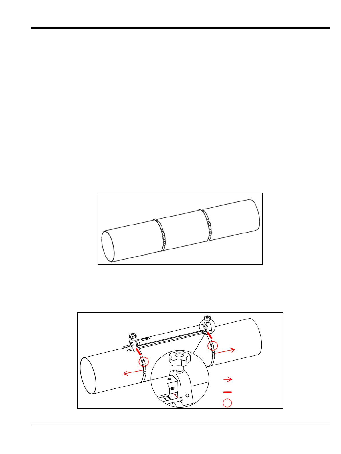
1. Install the AT600 clamp-on fixture with transducers on the pipe using two mounting straps.
a. Choose a location with enough straight pipe run (refer to Figure 7 on page 7).
b. Install the two mounting straps on the pipe about 12 in. (30 cm) apart (see Figure 10 below).
Figure 10: Mounting Straps Installed on Pipe
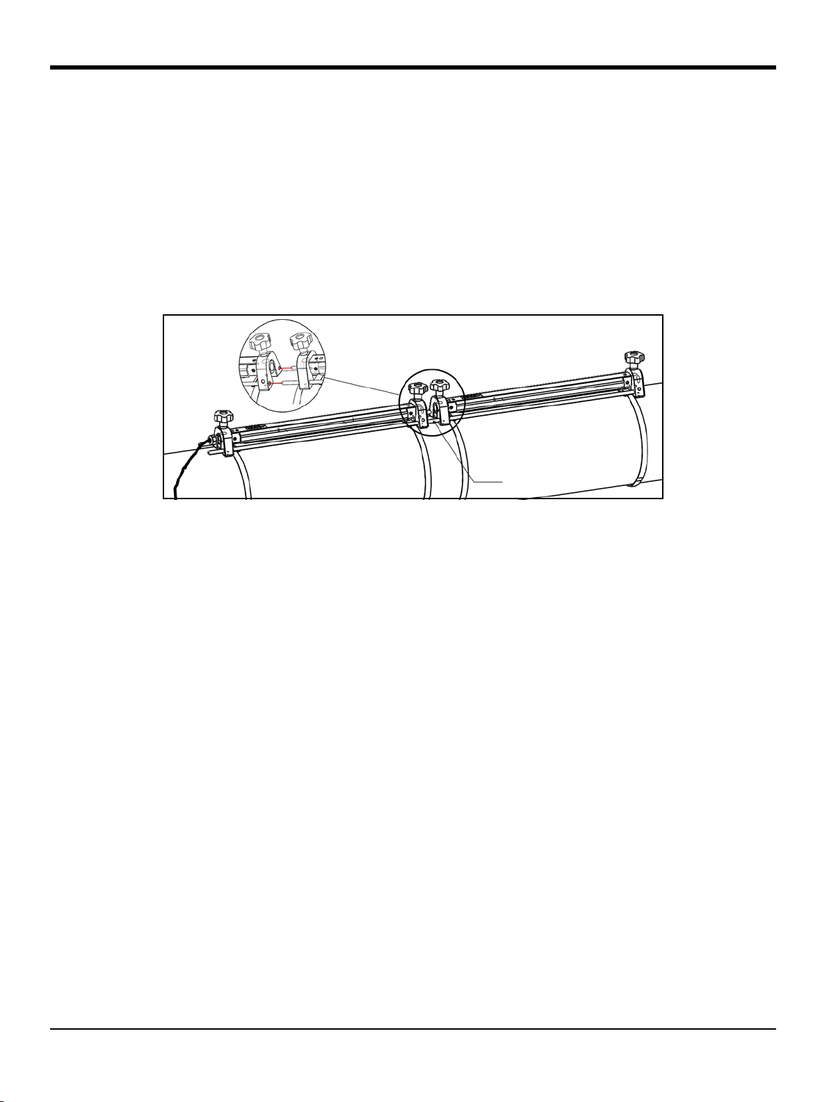
c. Hold the fixture against the pipe and move the mounting straps onto the fixture. Then, tighten
the screws on the straps, and verify that the straps remain in place on the fixture (see Figure 11
below).
AquaTrans™ AT600 User’s Manual 11
Page 24
Chapter 2. Clamp-On Fixture and Transducer Installation
Hand Wheel
Transducers
Sp
a
c
i
n
g
Couplant
Figure 11: 2 Traverse Installation with 1 Clamp-On Fixture
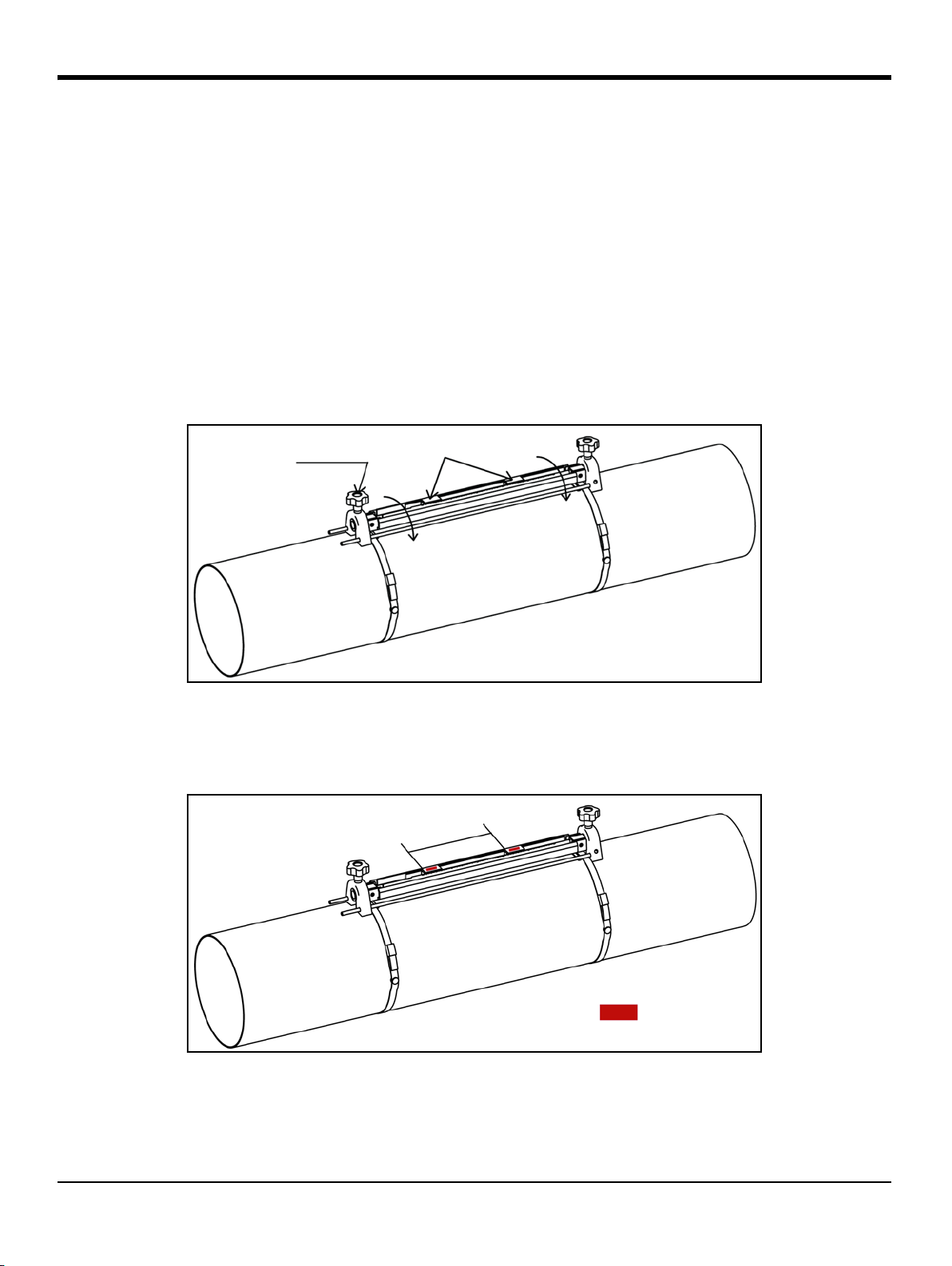
2.1.1 Transducer Spacing = 32 to 250 mm or 50 to 320 mm, Traverses = 2, Fixtures = 1 (cont.)
IMPORTANT: If there is any type of coating or protective layer on the outer pipe surface, it must be removed at
the locations where the transducers and the couplant contact the pipe surface.
2. Connect the power and transducer cables to the AT600, as shown in Figure 23 on page 23.
3. If you haven’t already done so, power the meter On and program your site data to determine the
required transducer spacing (see “Sensor Setup” on page 66).
4. Set the two transducers at the spacing calculated by the meter and tighten them in place, as follows:
a. Loosen both transducers and rotate the fixture so that the transducers are in view (see Figure 12
below).
Figure 12: Transducers Rotated into View
b. Set the transducers to the spacing calculated by the meter. If you are using solid couplant, apply it
to both transducer faces. Then, rotate the transducers back onto the rail (see Figure 13 below).
Figure 13: Set Transducer Spacing and Apply Couplant
12 AquaTrans™ AT600 User’s Manual
Page 25
Chapter 2. Clamp-On Fixture and Transducer Installation
UPSTREAM DOWNSTREAM
Spacing
LSL USL
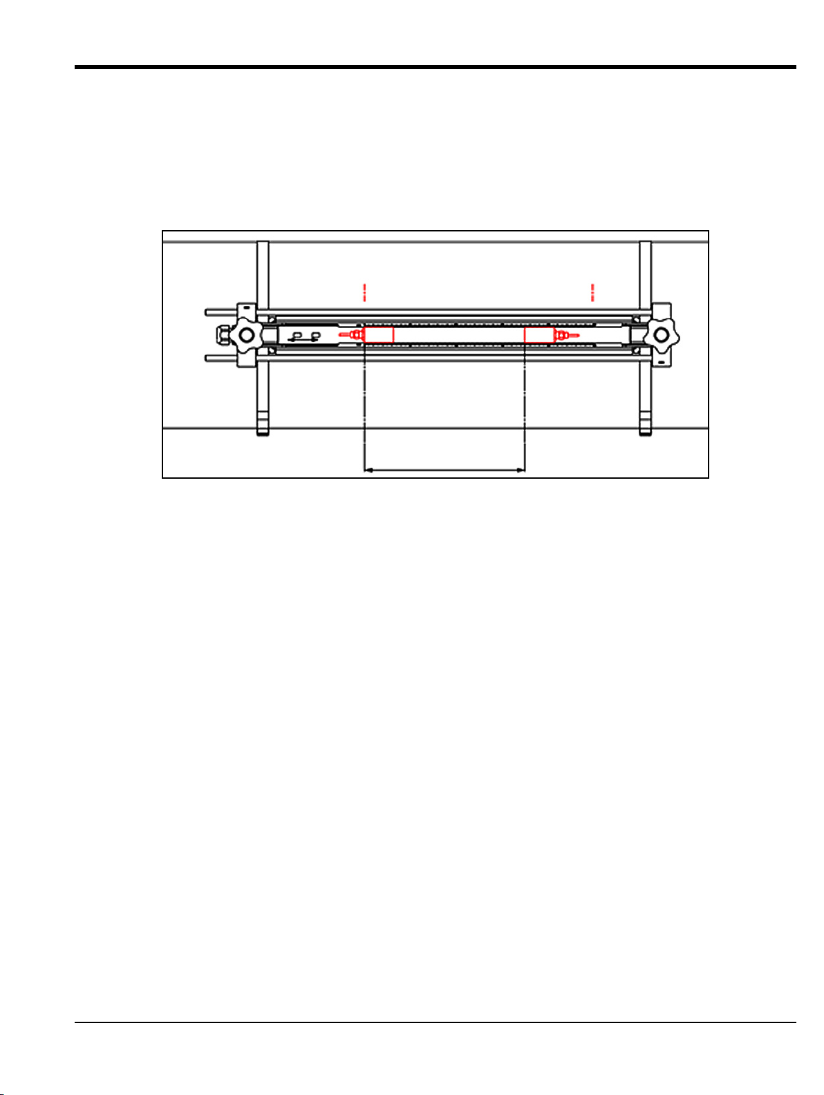
2.1.1 Transducer Spacing = 32 to 250 mm or 50 to 320 mm, Traverses = 2, Fixtures = 1 (cont.)
5. See Figure 14 below for an example of a completed installation. In this drawing, LSL is the Lower
Specified Limit and
USL is the Upper Specified Limit for the installation.
Note: For a one-fixture installation,
for a 1 MHz or 0.5 MHz transducer. The transducer spacing is measured from
LSL is 0 on the scale and USL is 250 mm for a 2 MHz transducer or 320 mm
LSL to a point USL.
Figure 14: Installation for 2 Traverses with 1 Fixture
6. Your clamp-on fixture and transducer installation is now complete. To wire your AT600 flow meter,
proceed to “Wiring the AT600 Electronics” on page 23.
AquaTrans™ AT600 User’s Manual 13
Page 26
Chapter 2. Clamp-On Fixture and Transducer Installation
Bar
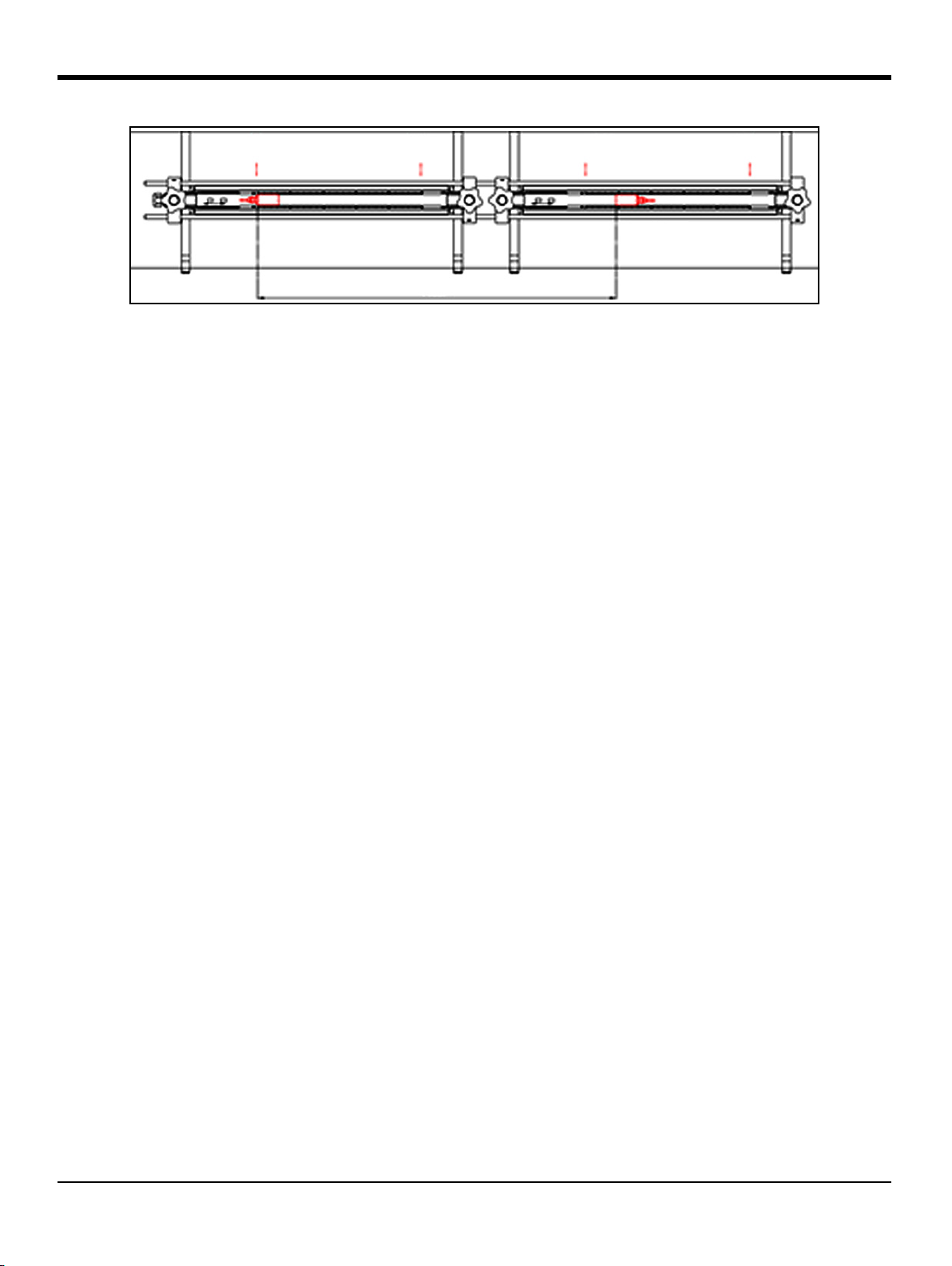
2.1.2 Transducer Spacing = 320 to 940 mm, Traverses = 2, Fixtures = 2
For a two traverse installation with a calculated transducer spacing of 320 to 940 mm for a 1 MHz or 0.5 MHz
transducer, two fixtures are installed on the same side of the pipe. To do so, complete the following steps:
1. Install the four mounting straps on the pipe with a spacing of 12 in. (30 cm) between each pair of
straps.
2. Hold one of the clamp-on fixtures, with two transducers and one cable, against the pipe between the
upstream pair of straps and move the two mounting straps onto the fixture (see Figure 15 below).
Then, tighten the screws on the mounting straps, and verify that the straps remain in place on the
fixture.
Figure 15: 2 Traverse Installation with 2 Clamp-On Fixtures
3. Repeat step 2 to install the second clamping fixture, with no transducers or cable, on the pipe
between the downstream pair of straps. Use the bar on the second fixture to connect the two fixtures.
Then, move the straps onto the second fixture and tighten the screws.
IMPORTANT: Be sure the bar on the left side of the second fixture is in close contact with the bar on the first
fixture.
4. Set the spacing between the two transducers in the upstream clamping fixture to the value
calculated by the meter and tighten them back onto the pipe, as follows:
a. Rotate the fixture so that the transducers are in view (see Figure 12 on page 12).
b. Remove the downstream transducer from the first fixture (see Figure 16 below), disconnect the
transducer cable, and route the cable into the second fixture. Then, install the downstream
transducer into the second fixture and reconnect the transducer cable. If you are using solid
couplant, apply it to both transducer faces. Then, rotate the transducers back onto the rail
14 AquaTrans™ AT600 User’s Manual
Page 27
Chapter 2. Clamp-On Fixture and Transducer Installation
UPSTREAM
DOWNSTREAM
UPSTREAM DOWNSTREAM
Spacing
LSL1
USL1 LSL2
USL2
0
300
620
Figure 16: Moving the Downstream Transducer
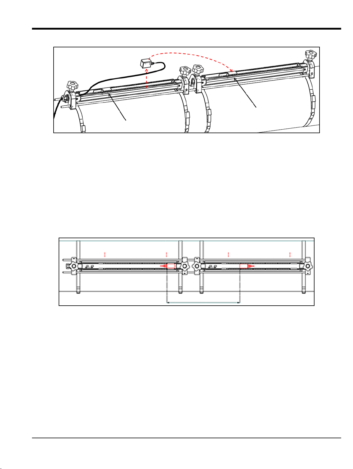
2.1.2 Transducer Spacing = 320 to 940 mm, Traverses = 2, Fixtures = 2 (cont.)
IMPORTANT: Tight contact must be made between the bars on the two fixtures to ensure an accurate spacing.
5. See Figure 17 and Figure 18 below for examples of a completed installation in the following
situations:
Note: In this drawing,
a. For a calculated transducer spacing of 320 to 620 mm for a 1 MHz or 0.5 MHz transducer, locate
the upstream transducer at the
transducer at the calculated transducer spacing position (
b. For a calculated transducer spacing of 620 to 940 mm for a 1 MHz or 0.5 MHz transducer, locate
the upstream transducer at the
transducer at the calculated transducer spacing position (between
fixture.
LSL is the Lower Specified Limit and USL is the Upper Specified Limit for each fixture.
USL1 position on the first fixture. Then, locate the downstream
USL2) on the second fixture.
Figure 17: Transducer Spacing of 320 to 620 mm with 2 Fixtures
LSL1 position on the first fixture. Then, locate the downstream
LSL2 and USL2) on the second
AquaTrans™ AT600 User’s Manual 15
Page 28
Chapter 2. Clamp-On Fixture and Transducer Installation
UPSTREAM DOWNSTREAM
250
Spacing
LSL1
USL1 LSL2
USL2
320
620
940
0
Figure 18: Transducer Spacing of 620 to 940 mm with 2 Fixtures
6. Your clamp-on fixture and transducer installation is now complete. To wire your AT600 flow meter,
proceed to “Wiring the AT600 Electronics” on page 23.
16 AquaTrans™ AT600 User’s Manual
Page 29
Chapter 2. Clamp-On Fixture and Transducer Installation
+
1
/
4
c
i
r
c
u
m
f
e
r
e
n
c
e
-
1
/
4
c
i
r
c
u
m
f
e
r
e
n
c
e
Band Tape
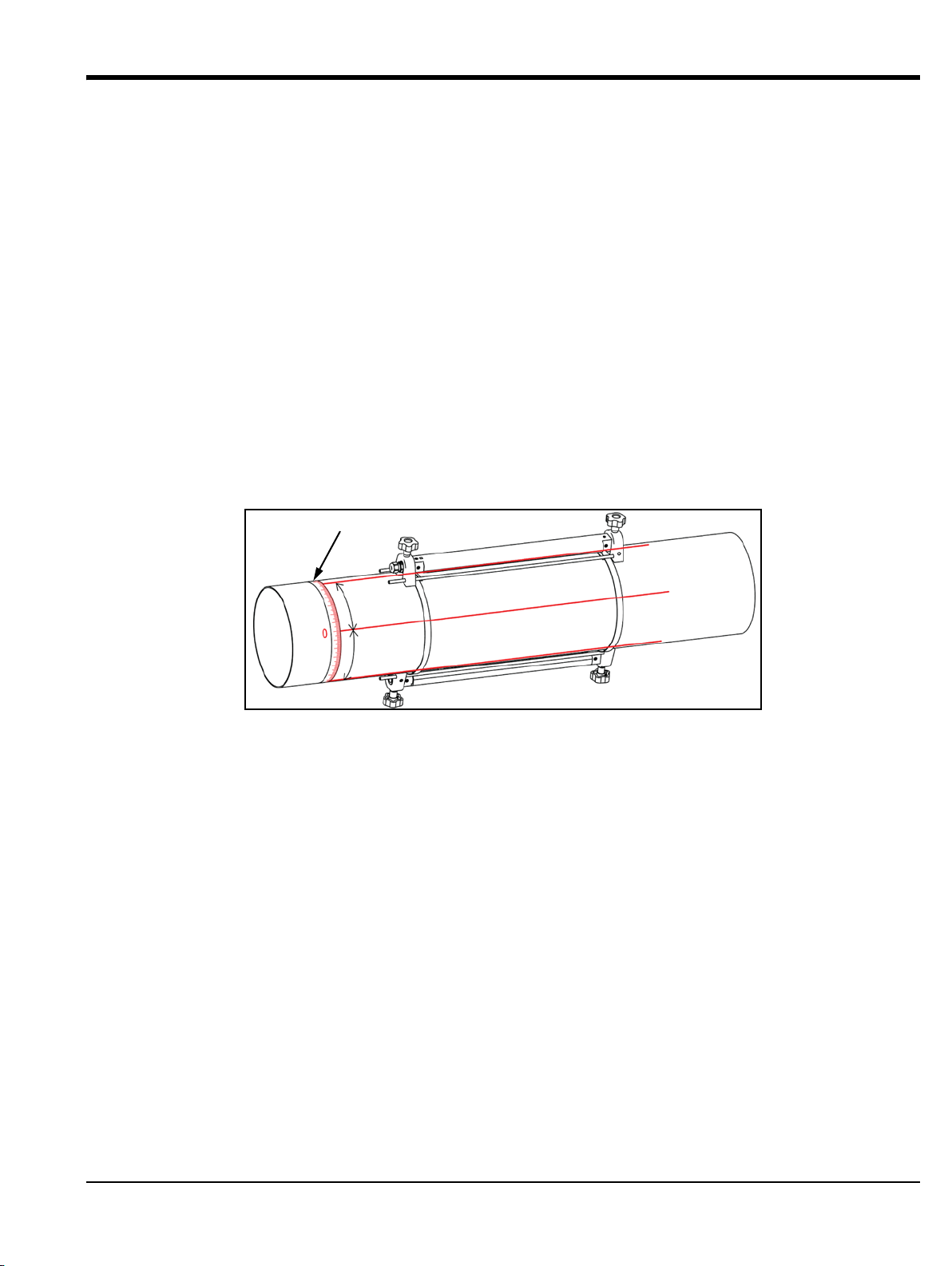
2.1.3 Transducer Spacing = 0 to 250 mm or 0 to 320 mm, Traverses = 1, Fixtures = 2
For a one traverse installation with a calculated transducer spacing of 0 to 250 mm for a 2 MHz transducer or
0 to 320 mm for a 1 MHz or 0.5 MHz transducer, two clamp-on fixtures are installed on opposite sides of the
pipe. To install this configuration, complete the following steps:
1. Mark a straight line parallel to the pipe centerline on the top of the pipe (i.e., the 12 o’clock position).
2. Use a band tape to measure the circumference of the pipe. Then, mark two additional lines on the
pipe parallel to the first line. Locate these lines 1/4 of the way around the pipe in each direction from
the original line (i.e., at the 3 o-clock and 9 o’clock positions).
3. Install two mounting straps on the pipe about 12 in. (30 cm) apart (see Figure 19 below).
4. Hold one clamp-on fixture, with two transducers and one cable, on the pipe along one of the lines
marked in step 2. Then, move the two straps onto the ends of this fixture.
5. Hold the remaining (empty) clamp-on fixture on the opposite side of the pipe from the first fixture.
Then, move the two straps onto the ends of this clamp-on fixture.
6. Align the two fixtures to be equal distances from the band tape. Tighten both straps securely.
Figure 19: 1 Traverse Installation with 2 Fixtures
AquaTrans™ AT600 User’s Manual 17
Page 30
Chapter 2. Clamp-On Fixture and Transducer Installation
UPSTREAM
DOWNSTREAM
2.1.3 Transducer Spacing = 0 to 250 mm or 0 to 320 mm, Traverses = 1, Fixtures = 2 (cont.)
7. Set the spacing between the two transducers to the value calculated by the meter as follows:
a. Loosen the fixture rails and rotate the rails so the transducers are in view.
b. Remove the upstream transducer from the first fixture (see Figure 20 below). Disconnect the
transducer cable and route the cable into the second fixture.
Note: The cable for the upstream transducer needs to be pulled out through one side of the rail on the first
fixture and inserted through the side of the rail on the second fixture.
c. Install the upstream transducer into the second fixture, and reconnect the transducer cable.
d. Locate the upstream transducer at the zero position of the second fixture, and then move the
downstream transducer to the required position on the first fixture. If you are using solid
couplant, apply it to both transducer faces. Then, rotate the transducers back onto the rail
Figure 20: Relocate the Upstream Transducer
8. Your clamp-on fixture and transducer installation is now complete. To wire your AT600 flow meter,
proceed to “Wiring the AT600 Electronics” on page 23.
18 AquaTrans™ AT600 User’s Manual
Page 31

Chapter 2. Clamp-On Fixture and Transducer Installation
+
1
/
4
c
i
r
c
u
m
f
e
r
e
n
c
e
-
1
/
4
c
i
r
c
u
m
f
e
r
e
n
c
e
U
P
S
T
R
E
A
M
D
O
W
N
S
T
R
E
A
M
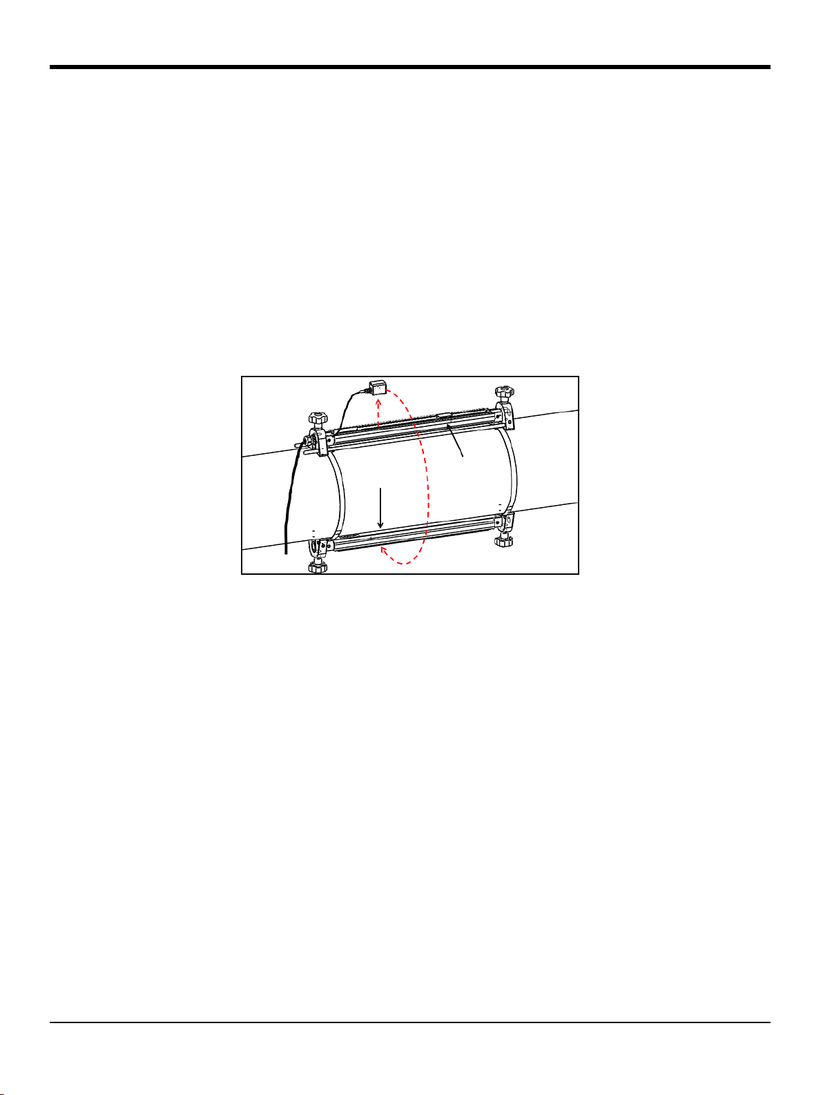
2.1.4 Transducer Spacing >320 mm, Traverses = 1, Fixtures = 2
For a one traverse installation with a calculated transducer spacing of >320 mm for a 1 MHz or 0.5 MHz
transducer, two clamp-on fixtures are installed on opposite sides of the pipe. To install this configuration,
refer to Figure 21 below and complete the following steps:
1. Mark a straight line parallel to the pipe centerline on the top of the pipe (i.e., the 12 o’clock position).
2. Use a band tape to measure the circumference of the pipe. Then, mark two additional lines on the
pipe parallel to the first line. Locate these lines 1/4 of the way around the pipe in each direction from
the original line (i.e., at the 3 o-clock and 9 o’clock positions).
3. Install the four mounting straps on the pipe with a spacing of about 12 in. (30 cm) between each pair
of straps. Then, mark a fixture position on each of the straight lines, using the band tape as a
reference point.
4. Hold one clamp-on fixture, with two transducers and one cable, on the pipe between the pair of
downstream straps and along one of the lines marked in step 2. Then, move the two downstream
straps onto the ends of this clamp-on fixture. Tighten the strap screws and verify that the straps
remain on the ends of the fixture.
5. Hold the remaining (empty) clamp-on fixture along the line on the opposite side of the pipe from the
first fixture and between the upstream pair of straps. Then, move the two upstream straps onto the
ends of this clamp-on fixture. Tighten the strap screws and verify that the straps remain on the ends
of the fixture.
6. Set the spacing between the two transducers to the value calculated by the meter as follows:
a. Loosen the fixture rails and rotate the rails so the transducers are in view.
b. Remove the upstream transducer from the first fixture (see Figure 21 below). Disconnect the
transducer cable and route the cable into the second fixture.
c. Install the upstream transducer in the second fixture, and reconnect the transducer cable.
d. Locate the upstream transducer at the zero position of the second fixture, and then move the
downstream transducer to the required position on the first fixture. If you are using solid
couplant, apply it to both transducer faces. Then, rotate the transducers back onto the rail
Figure 21: 1 Traverse Installation for Transducer Spacing >320 mm
7. Your clamp-on fixture and transducer installation is now complete. To wire your AT600 flow meter,
proceed to “Wiring the AT600 Electronics” on page 23.
AquaTrans™ AT600 User’s Manual 19
Page 32

Chapter 2. Clamp-On Fixture and Transducer Installation
Transducer
BNC to SMA Adapter
AT6 Cable with SMA Plug
with BNC Connector
2.2 Installing a CF-ES Clamp-On Fixture and Transducer System
To use the AT600 flow meter on 0.5 to 2 in. (15 to 50 mm) pipes, the CF-ES clamp-on fixture must be used.
UTXDR or CF-LP transducers are available for installation in this fixture. Note the following specifications:
• UTXDR Transducer: Use cable adapter p/n 704-1678-LF with the AT6 transducer cable,
-40 to +120°C (-40 to +248°F) Temperatures, 4 MHz Frequency
• CF-LP Transducer: Use cable adapter p/n 210-410-LF with the AT6 transducer cable,
up to 230°C (446°F) Temperatures, 4 MHz Frequency.
Detailed installation instructions for this fixture and transducer are available in BHGE document #916-082.
2.3 Installing a General Clamping Fixture and Transducer System
Both the C-RS and C-PT transducers are mounted on the pipe with the BHGE General Clamping Fixture (GCF).
For detailed installation instructions refer to following:
• C-RS Transducer Installation Guide (BHGE document #916-077)
• C-PT Transducer Installation Guide (BHGE document #916-074)
2.3.1 Installing C-RS or C-PT Transducers with an RG316 Cable
The standard AT6 transducer cable is an RG316 cable with an SMA connector on the transducer end. To
connect the
cable, a BNC to SMA Adapter is needed. See Figure 22 below and install the cable adapter on the transducer
end of your AT6 cable.
BNC connector on the C-RS or C-PT transducer to the SMA connector on the AT6 transducer
Figure 22: BNC to SMA Cable Adapter Installation
20 AquaTrans™ AT600 User’s Manual
Page 33

Chapter 2. Clamp-On Fixture and Transducer Installation
2.3.2 Installing C-RS or C-PT Transducers with an RG62 Cable
The AT600 flow meter can be connected directly to a C-RS or C-PT transducer with an optional RG62 cable,
which has a BNC connector at transducer end. Thus, the BNC to SMA Adapter is not needed.
This RG62 cable has a submersible cable option for the C-RS transducer. Also, there is a junction box option
for the C-RS and C-PT transducers, which provides extra physical protection for the BNC connection on the
transducer.
AquaTrans™ AT600 User’s Manual 21
Page 34

Chapter 2. Clamp-On Fixture and Transducer Installation
22 AquaTrans™ AT600 User’s Manual
Page 35

Chapter 3. Wiring the AT600 Electronics
GROUNDING 4
A
GROUNDING 2
GROUNDING 1
GROUNDING 3
DETAIL A
Transducer Terminals
W/E >ĂďĞů ĞƐĐƌŝƉƟŽŶ
ϭ E ŽǁŶƐƚƌĞĂŵdƌĂŶƐĚƵĐĞƌ
Ϯ hW hƉƐƚƌĞĂŵdƌĂŶƐĚƵĐĞƌ
WŽǁĞƌdĞƌŵŝŶĂůƐ
W/E >ĂďĞů ĞƐĐƌŝƉƟŽŶ
ϭ >ϭ;нͿ >;нͿ>ŝǀĞWŽǁĞƌWŽƐŝƟǀĞ
Ϯ >ϮE;ͲͿ E;ͲͿEĞƵƚƌĂůEĞŐĂƟǀĞ
/ŶƉƵƚKƵƚƉƵƚdĞƌŵŝŶĂůƐ
>ĂďĞů ĞƐĐƌŝƉƟŽŶ
Ϭ ŶĂůŽŐKƵƚƉƵƚϰͲϮϬŵ,ZdWŽƐŝƟǀĞ
ϭ ŶĂůŽŐKƵƚƉƵƚϰͲϮϬŵ,ZdEĞŐĂƟǀĞ
Ϯ ^ĞƌǀŝĐĞDŽĚďƵƐWŽƌƚWŽƐŝƟǀĞ
ϯ ^ĞƌǀŝĐĞDŽĚďƵƐWŽƌƚEĞŐĂƟǀĞ
ϰ ^ĞƌǀŝĐĞDŽĚďƵƐWŽƌƚZĞƚƵƌŶ'ƌŽƵŶĚ
ϱ ƵƐƚŽŵĞƌDŽĚďƵƐWŽƌƚWŽƐŝƟǀĞ
ϲ ƵƐƚŽŵĞƌDŽĚďƵƐWŽƌƚEĞŐĂƟǀĞ
ϳ ƵƐƚŽŵĞƌDŽĚďƵƐWŽƌƚZĞƚƵƌŶ'ƌŽƵŶĚ
ϴ ŝŐŝƚĂůKƵƚƉƵƚWŽƌƚWŽƐŝƟǀĞ
ϵ ŝŐŝƚĂůKƵƚƉƵƚWŽƌƚEĞŐĂƟǀĞ
ŝŐŝƚĂůKƵƚƉƵƚWŽƌƚWŽƐŝƟǀĞ
ŝŐŝƚĂůKƵƚƉƵƚWŽƌƚEĞŐĂƟǀĞ
E
'ĂƚĞ/ŶƉƵƚWŽƌƚWŽƐŝƟǀĞ
'ĂƚĞ/ŶƉƵƚWŽƌƚEĞŐĂƟǀĞ
& E
EŽƚĞŶĂůŽŐŽƵƚƉƵƚƐĂƌĞEĂŵƵƌEϰϯĐŽŵƉůŝĂŶƚ
Chapter 3. Wiring the AT600 Electronics
3.1 Wiring Diagram
ATTENTION EUROPEAN CUSTOMERS! To meet CE Mark requirements, all cables must be installed
as described in “Wiring Cable Specifications and Requirements” on page 177.
This section includes instructions for making all the necessary electrical connections to the AT600 flow
meter. Refer to Figure 23 below for the complete wiring diagram of the meter.
IMPORTANT: Except for the transducer connector, all electrical connectors are stored in their terminal blocks
during shipment and may be removed from the enclosure for more convenient wiring. Feed the
cables through the cable gland holes on the bottom of the enclosure, attach the wires to the
appropriate connectors and plug the connectors back into their terminal blocks.
After the AT600 is completely wired, proceed to “Initial Setup and Programming” on page 31 to configure the
meter for operation.
Note: The HART and Modbus communication options must be selected when ordering the AT600.
AquaTrans™ AT600 User’s Manual 23
Figure 23: Wiring Diagram
Page 36

Chapter 3. Wiring the AT600 Electronics
GLAND HOLE 5
GLAND HOLE 4
GLAND HOLE 2
GLAND HOLE 1
GLAND HOLE 3
DETAIL B
B
CABLE GLAND HOLES
Hole Num. Feed-Through Cables
1 Power Lines
2 Digital Output B Cable Lines
Digital Output C Cable Lines
Gate Input Cable Lines
3 Service Modbus Cable Lines
Customer Modbus Cable Lines
4 Analog Output A Cable Lines
5 Transducer Cable Lines
3.1 Making the Electrical Connections (cont.)
For proper wiring, the power lines, transducer cable and I/O lines must be routed through the appropriate
cable glands (see Figure 24 below). Also, refer to “Wiring Cable Specifications and Requirements” on page 177
for the required cable specifications.
IMPORTANT: Any unused cable glands must be plugged with the cable gland inserts provided with meter.
Figure 24: Recommended Cable Gland Usage
24 AquaTrans™ AT600 User’s Manual
Page 37

Chapter 3. Wiring the AT600 Electronics
3.2 Wiring the Line Power
ATTENTION EUROPEAN CUSTOMERS! To meet CE Marking requirements, all cables must be
installed as described in “Wiring Cable Specifications and Requirements” on page 177.
The AT600 may be ordered for operation with power inputs of either 85-264 VAC or 12-28 VDC. The label on
the shroud inside the electronics enclosure lists the required line voltage for your meter.
WARNING! Be sure to connect the AT600 only to the specified line voltage.
Examples of AT600 labels indicating the required line voltage are shown in Figure 25 below.
ATTENTION EUROPEAN CUSTOMERS! For compliance with the European Union's Low Voltage
Directive, this unit requires and external power disconnect device such as a switch or circuit breaker.
The disconnect device must be marked as such, clearly visible, directly accessible, and located within
1.8 m (6 ft) of the unit.
Figure 25: Typical Meter S/N Label (AC and DC Versions)
AquaTrans™ AT600 User’s Manual 25
Page 38

Chapter 3. Wiring the AT600 Electronics
3.2 Wiring the Line Power (cont.)
Refer to Figure 23 on page 23 to locate the terminal block and connect the line power as follows:
WARNING! Improper connection of the line power leads or connecting the meter to the incorrect
line voltage will damage the unit. It will also result in hazardous voltages at the flowcell and
associated piping and within the electronics console.
1. Strip 1/4” of insulation from the end of the line and neutral AC leads (or the positive and negative DC
leads), and 1/2” of insulation from the end of the ground lead.
2. Connect the ground lead to the internal ground connection (
panel of the electronics enclosure (See Figure 23 on page 23).
IMPORTANT: The incoming ground lead must be connected to the internal ground connection.
3. Connect the neutral AC lead (or the negative - DC lead) to
DC lead) to
IMPORTANT: Do not remove the existing PC board ground wire or the cover ground wire.
L1(+), as shown in Figure 23 on page 23.
GROUNDING 1) located on the bottom
L2/N(-) and the AC line lead (or the positive
3.3 Wiring the Transducers
ATTENTION EUROPEAN CUSTOMERS! To meet CE Mark requirements, all cables must be installed
as described in “Wiring Cable Specifications and Requirements” on page 177.
Wiring a typical AT600 system requires interconnection of the following components:
• Upstream and downstream transducers Installed in the clamping fixtures)
• The electronics console
To wire the transducers, complete the following steps:
WARNING! Before connecting the transducers, take them to a safe area and discharge any static
build-up by shorting the center conductor of the transducer cables to the metal shield on the cable
connector.
1. Locate the two transducer cables and connect them to the transducers.
2. Connect the cable connector with yellow
connector with white
3. Secure the cable gland.
IMPORTANT: Be sure to insert all cable connectors straight into the PCB receptacles to avoid damaging the
connector and/or the receptacle.
26 AquaTrans™ AT600 User’s Manual
UP jacket on the cable to the UP terminal, as shown in Figure 23 on page 23.
DN jacket on the cable to the DN terminal, and connect cable
Page 39

3.4 Wiring the System Ground
DETAIL C
SYSTEM GROUNDING SCREW
Model AT600
(Int. Pwr. Sup.)
HART Master/
Ampere Meter
Volts +
(Common)
Volts -
600 ohms)
(maximum
Load
PIN: 1
PIN: 0
WARNING! The AT600 must always be connected to a proper earth ground, using the system
grounding screw shown in Figure 26 below.
Figure 26: System Grounding Screw
3.5 Wiring the Analog Output for HART Communication
Chapter 3. Wiring the AT600 Electronics
The standard configuration of the Model AT600 flow meter includes one isolated 0/4-20mA analog output.
Connections to this output may be made with standard twisted-pair wiring. The current loop impedance for
this circuit must not exceed 600 ohms.
Figure 27: Analog Output/HART Communication Wiring
AquaTrans™ AT600 User’s Manual 27
Page 40

Chapter 3. Wiring the AT600 Electronics
3.5 Wiring the Analog Output for HART Communication (cont.)
WARNING! Always be sure to disconnect the main power supply from the AT600 before proceeding
with these instructions.
To wire the analog output, refer to Figure 27 on page 27 and complete the following steps:
1. Verify that the main power has been disconnected from the unit, and then open the enclosure.
2. Install the required cable gland in the chosen gland hole on the bottom of the enclosure.
3. Refer to Figure 23 on page 23 for the location of terminal block
shown above.
4. Secure the cable clamp.
Note the following:
I/O, and wire the terminal block as
• The standard analog output port provides only a 0/4-20mA analog output. If the HART
communication option is desired, it must be specified at the time of purchase.
• The AT600 analog output is an active mode type, with power provided internally by the meter. Do not
connect an external 24V power supply to this circuit.
• Prior to use, the analog output must be set up and calibrated (see “Inputs/Outputs” on page 48).
• When in meter is in configuration mode, the analog output is locked at 3.6 mA. After exiting from
configuration mode, the meter will resume normal operation.
3.6 Wiring the Modbus Communication
The optional AT600 Modbus port is a two-wire, half-duplex RS485 interface. If this option was specified at
the time of purchase, proceed with the wiring instructions below.
WARNING! Always be sure to disconnect the main power supply from the AT600 before proceeding
with these instructions.
To wire the Modbus RS485 serial port, refer to Figure 23 on page 23 above and complete the following steps:
1. Verify that the main power has been disconnected from the unit, and then open the enclosure.
2. Install the required cable clamp in the chosen gland hole on the side of the electronics enclosure.
3. Route one end of the cable through the gland hole and wire it to terminal block.
4. Secure the cable clamp.
28 AquaTrans™ AT600 User’s Manual
Page 41

Chapter 3. Wiring the AT600 Electronics
Model AT600
Totalizer/Frequency Counter
or Alarm Detector
PIN: 9/B
PIN: 8/A
C: Isolated Return
(Int. Pwr. Sup.)
Volts +
(Common)
Volts -
10 Kohms)
(minimum
Load
Max. Current:
Max. Voltage:
Isolation Voltage:
Max. Load Power:
1A
100 V
500 V
2W IN
3.7 Wiring the Frequency/Totalizer/Alarm Output
The AT600 can accommodate up to two digital outputs. Each of these outputs can be configured as either a
totalizer, frequency or alarm output (see “Programming Digital Communications” on page 61 for instructions).
Each totalizer/frequency/alarm output requires a twisted pair cable. Wire the terminal block as shown in
Figure 23 on page 23 and Figure 28 below.
Figure 28: Totalizer/Frequency/Alarm Output Wiring
AquaTrans™ AT600 User’s Manual 29
Page 42

Chapter 3. Wiring the AT600 Electronics
Model AT600
PIN: E
PIN: D
Switch
C
NO
+5 V
3.8 Wiring the Gate Input
The AT600 provides a Gate Contact Input port. This port is designed to start/stop the totalizer. During normal
measurement mode, thee operator can start or stop the totalizer functionality by toggling the gate switch.
WARNING! Always be sure to disconnect the main power supply from the AT600 before proceeding
with these instructions.
To wire the Gate input, refer to Figure 23 on page 23 and Figure 29 below and complete the following steps:
1. Verify that the main power has been disconnected from the unit, and then open the enclosure.
2. Install the required cable clamp in the chosen gland hole on the side of the electronics enclosure.
3. Route one end of the cable through the gland hole and wire it to terminal block.
4. Secure the cable clamp.
Figure 29: Gate Input Wiring
30 AquaTrans™ AT600 User’s Manual
Page 43

Chapter 4. Initial Setup and Programming
Display
Main Menu
Display Format
Program
Password
xxxx
User Preferences
Input/Output
Sensor Setup
Calibration
Advanced Factory
Program Review Keypad Lockout
Language
Save Changes?
No
Yes
Display
Chapter 4. Initial Setup and Programming
4.1 Introduction
This chapter provides instructions for programming the AT600 flow meter to place it into service. Before the
AT600 can begin taking measurements, at least the following menus must be programmed:
• “User Preferences” on page 43
• “Inputs/Outputs” on page 48
• “Sensor Setup” on page 66
Refer to the Main Menu map in Figure 30 below, and proceed to the appropriate section for instructions.
Figure 30: Main Menu Map
AquaTrans™ AT600 User’s Manual 31
Page 44

Chapter 4. Initial Setup and Programming
AT600
INITIALIZE . .
0.0
Velocity
m/s
Soundspeed
m/s
0.0
4.2 AT600 Keypad Operation
There are six keys and two LEDs on the AT600 keypad. The green light is a system health indicator and is on
when the meter is operational and not in error. The red light is a system status indicator and is on when the
meter is in error. Both lights being off indicates that the system is in configuration mode or no power has
been applied to the meter.
Figure 31: The AT600 Keypad
The six keys on the keypad enable users to program the AT600:
• [] - confirms the choice of a specific option and all data entry within that option
• [] - enables users to exit from a specific option without saving unconfirmed data
• [] and [] - enable users to highlight a specific window in the display option or to scroll through a
list of options. They are also used to change individual characters in a text string.
• [] and [] - enable users to scroll to a specific menu option, or to highlight a specific character in a
text string.
When powered On, the AT600 initialization screen is shown, followed by a measurement display (see below).
As a guide in following the programming instructions in this chapter, the complete AT600 menu maps can be
found in “Menu Maps” on page 187, and the relevant portions are reproduced throughout this chapter.
IMPORTANT: If no key has been pressed for 5 minutes, the AT600 exits the Keypad Program and returns to
32 AquaTrans™ AT600 User’s Manual
displaying measurements. Any unconfirmed configuration changes are discarded.
Page 45

Chapter 4. Initial Setup and Programming
Velocity
m/s
0.0
0.0
Velocity
m/s
Soundspeed
m/s
0.0
Total m^3
Forward 0.0
Reverse 0.0
Velocity
m/s
0.0
Measurement Type
Value
Error Code
Value Units
Velocity
m/s
0.0
m/s
Velocity
0.0
4.3 Display Programming
The AT600 keypad has six keys (see “AT600 Keypad Operation” on page 32) and the following two LEDs:
• Green: The green LED is a system health indicator and it is On when the meter is operating without
error.
• Red: The red LED is a system status indicator and it is On whenever the meter is in error.
Note: When both LEDs are Off, the meter is either in configuration mode or no power is applied.
4.3.1 Changing the Display for One- or Two-Variable Screens
An outline of a typical one- or two-variable screen is shown below.
To change the number of decimal places in the displayed value:
From the display screen, press either the [] or [] keys until the value is
highlighted.
AquaTrans™ AT600 User’s Manual 33
After the value is highlighted, press
option.
[] to open the Display/Decimal
Page 46

Chapter 4. Initial Setup and Programming
Display/Decimal
2
3
4
Sci
Velocity
m/s
0.0
m/s
Velocity
0.000e+00
Velocity
Measurement Type
Act Volumetric
Std Volumetric
Mass
4.3.1 Changing Display for One- or Two-Variable Screens (cont.)
Use the [] and [] keys to scroll to the desired value. (Available
options include 0, 1, 2, 3, 4, and Sci (Scientific Notation). Press [
select the value, and then press [
t
o cancel the selection.
] again to confirm the selection or []
4.3.2 Changing the Measurement Type for One- or Two-Variable Screens
To change the measurement type:
From the display screen, press either the [] or [] keys until the
measurement type is highlighted.
] to
After the value is highlighted, press
option.
The screen changes to Display/Measurement Type. Press the [] and []
keys to scroll to the desired parameter. Available parameters include:
Velocity, Act Volumetric, Std volumetric, Mass, Batch Totals, Inventory
Totals, Soundspeed, Reynolds, KFactor, and Diagnostics. After you have
chosen the measurement type, press
press [
Note: To select a particular measurement unit, go to “Units Setting” on page 44.
] again to confirm the selection or [] to cancel the selection.
[] to open the Measurement Type
[] to select the value, and then
34 AquaTrans™ AT600 User’s Manual
Page 47

Chapter 4. Initial Setup and Programming
Total m^3
Forward 0.000e+00
Reverse 0.000e+00
Totalizer
Reset Totalizer
Error Code
Values
Measurement Type
Start/Stop Totalizer
Totalizer Units
TOTAL m^3
Forward 0.000e+00
Reverse 0.000e+00
Total m^3
Forward 0.000e+00
Reverse 0.000e+00
Display/Decimal
2
3
4
Sci
4.3.3 Changing the Measurement Type or Units for the Totalizer Screens
The totalizer screen opens similar to Figure 32 below.
Figure 32: The Totalizer Screen
To change the number of decimal places in the value displayed on a totalizer screen, proceed as follows:
From the display screen, press either the [] or [] keys until the value
is highlighted.
After the value is highlighted, press
[] to open the Display/Decimal option.
Use the [] and [] keys to scroll to the desired number of decimal
places. (Available options include 0, 1, 2, 3, 4, and Sci (Scientific Notation).
Press [
selection or
] to select the value, and then press [] again to confirm the
[] to cancel the selection.
AquaTrans™ AT600 User’s Manual 35
Page 48

Chapter 4. Initial Setup and Programming
TOTAL m^3
Forward 0.000e+00
Reverse 0.000e+00
Total m^3
Forward 0.000e+00
Reverse 0.000e+00
Forward Totals
Totalizer Type
Reverse Totals
Net Totals
Time
TOTAL Seconds
Time 0.0000
Reverse 0.000e+00
Display/Unit
Seconds
Minutes
Hours
Days
4.3.3 Changing the Measurement Type or Units for the Totalizer Screens (cont.)
To change the totalizer measurement type, proceed as follows:
From the display screen, press either the [] or [] keys until the
measurement type is highlighted.
After the type is highlighted, press
[] to open the Display/Decimal option.
The screen changes to Totalizer Type. Press the [] and [] keys to scroll to
Forward Totals,
If the first value is set to
Reverse Totals,
or Net Totals, the meter displays the selected unit in the Units Setting selection. The available
the desired parameter. Available parameters include:
Reverse Totals, Net Totals and Time
[] to select the value, and then press [] again to confirm the selection or
[
] to cancel the selection.
Time, the meter displays the time unit. If the first value is set to Forward Totals,
. After you have chosen the type, press
time measurement units are seconds, minutes, hours or days. To choose the appropriate units, from the
highlighted measurement type, press the [] or [] keys until the desired measurement unit is highlighted.
After the unit is highlighted, press
[] to open the Display/Unit option.
36 AquaTrans™ AT600 User’s Manual
Press the
[] and [] keys to scroll to the desired units, and press [] to
select the unit, and then press [
cancel the selection.
Note: If you selected
Time, the available units are seconds, minutes, hours
and days.
] again to confirm the selection or [] to
Page 49

4.3.4 Starting or Stopping the Totalizer Measurement
TOTAL m^3
Forward 0.000e+00
Reverse 0.000e+00
TOTAL m^3
Forward 0.000e+00
Reverse 0.000e+00
TOTAL m^3
Forward 0.000e+00
Reverse 0.000e+00
To start or stop totalizer measurements:
Chapter 4. Initial Setup and Programming
From the display, press either the [] or [] keys until the
(either an arrow icon for
After the value is highlighted, press [
Start or a two-bar icon for Stop) is highlighted.
] to start or stop totalizing.
The display icon then changes to indicate the new status (
Start/Stop icon
Start or Stop).
AquaTrans™ AT600 User’s Manual 37
Page 50

Chapter 4. Initial Setup and Programming
TOTAL m^3
Forward 0.000e+00
Reverse 0.000e+00
TOTAL m^3
Forward 0.000e+00
Reverse 0.000e+00
4.3.5 Resetting the Totalizer
To reset the totalizer, proceed as follows:
From the display screen, press either the [] or [] keys until the
icon (a partial circle with an arrow) is highlighted.
After the
Reset icon has been highlighted, press [] to reset the totalizer to 0.
Reset
38 AquaTrans™ AT600 User’s Manual
Page 51

4.4 Entering the Main Menu
Display Format
Program
Program Review Keypad Lockout
Language
ѝ᮷
Français
ᰕᵜ䃎
English
Deutsch
Italiano
ƴǗǕǕǎnjǍPortuguês
Española
Yes
No
Svenska
1 Variable
2 Variables
Totalizer
Turkish
Main Menu
Esc > Enter > Esc
Display
Locked
Unlocked
Velocity
m/s
0.0
Chapter 4. Initial Setup and Programming
Figure 33: The Main Menu Map
4.4.1 Display Format
To begin programming your meter, you must select the system units as discussed below. Remember to
record all programming data in Appendix B, Data Records.
Display Format submenu is used to set up the type of format to be used in displaying information.
The
On the initial screen, use the arrow keys to highlight the lock symbol
and press [√].
The following screen opens.
AquaTrans™ AT600 User’s Manual 39
Page 52

Chapter 4. Initial Setup and Programming
Display
Display Format
Program
Program Review
Keypad Lockout
Display/Display Format
Two Variable
Totalizer
One Variable
Display
Display Format
Program
Program Review
Keypad Lockout
Lockout/ Keypad Lockout
Yes
No
4.4.1 Display Format (cont.)
4.4.2 Keypad Lockout
Use the [] or [] keys to highlight Display Format and press []. The
following screen opens.
Use the [] and [] arrow keys to highlight the desired format setup and
[] to return to the previous screen.
press
To lock or unlock the keypad for security, on the
Keypad Lockout and press []. A screen similar to the following opens.
To lock the display, use the [] and [] keys to highlight
[]. The screen returns to the previous display.
To unlock the display, use the [] and [] keys to highlight
[]. The screen returns to the previous display.
Note: When the keypad is locked, press
[], [], [] to unlock it.
Display menu, select
Yes and press
No and press
40 AquaTrans™ AT600 User’s Manual
Page 53

4.4.3 Language
Display
Language
Program
Program Review
Keypad Lockout
Display/Language
Deutsch
中文
Français
English
Display
Main Menu
Display Format
Program
Password
xxxx
User Preferences
Input/Output
Sensor Setup
Calibration
Advanced Factory
Program Review Keypad Lockout
Language
Save Changes?
No
Yes
Display
Chapter 4. Initial Setup and Programming
To change the display language, on the
Display menu, select Language and
press [√]. A screen similar to the following opens.
Use the [] and [] arrow keys to highlight the desired language and
press [√] to return to the previous screen. The display language is
changed to the new selection.
4.4.4 Program and Program Review Menus
The Program and Program Review menus allow setting up or viewing of several categories of information. As
discussed, to edit parameters, you need to input a valid password. The next section describes the access
levels required to edit various parameters. To view all parameters without editing, select
Program Review.
AquaTrans™ AT600 User’s Manual 41
Figure 34: Program and Program Review Menu Map
Page 54

Chapter 4. Initial Setup and Programming
Display
Display Format
Program
Program Review
Keypad Lockout
Enter the password
9999
]MOVE
]UNDO [ ]SAVE
]
]
]
]MODF
4.4.4.1 Program Review
The Program Review menu requires no user password. However, it provides view-only access to the
information. To change any setting or parameter, you must enter the
Program Menu by entering a valid
password.
4.4.4.2 Program
IMPORTANT: When you enter Program (configure) mode, measurements stop and the output goes to error level.
To enter the
to highlight
Programming menu, on the Display menu use the arrow keys
Program and press [√]. The following screen opens.
Use the [] or [] key to select a specific digit, then use the [] or [] key
to change that digit as required. After all digits are correct, press
open the
Note: The default password is
User Preference screen.
1111.
[] to
42 AquaTrans™ AT600 User’s Manual
Page 55

4.5 User Preferences
User Preference
Units Setting
Density
Password
Setting
System Date
Setting
Meter Tag
Label
System Date
Setting
Meter Tag
Label
Set System Time
Date: 11 / 12 / 2013
Time: 08 : 09 : 10
]MOVE
]UNDO [ ]SAVE
]
]
]MODF
[
4.5.1 Setting
Chapter 4. Initial Setup and Programming
To check or change the desired settings, under User Preference, select
Settings and press []. The following screen opens.
To check the
Meter Tag and/or Label, highlight your choice on the Setting
menu and press []. Press [] to return to the previous screen.
Note: You can only change the
Meter Tag and Label data using BHGE’s
Vitality software.
To check or change the date/time, highlight
System Date and press []. The
following screen opens.
Use the [] or [] key to select a specific digit, then use the [] or [] key
to change that digit as required. After all digits are correct, press
save. Then, press [
] to return to the previous screen.
[] to
AquaTrans™ AT600 User’s Manual 43
Page 56

Chapter 4. Initial Setup and Programming
User Preference
Settings
Units Setting
Density
Password
Units Setting
Velocity
Act Volumetric
Std Volumetric
Mass
UnitsSet / Velocity
No
Yes
UnitsSet /Velocity
English
Metric
Vel /
Ft/s
4.5.2 Units Setting
To check or change velocity flow units, use the [] or [] arrow key to
select
Units Setting and press []. The following screen opens.
Under
Units Setting menu, use the [] or [] arrow key to select the unit
that need to be changed and press [√] to open the following screen.
Note:
If you don’t want to change the selected unit, select
you do want to change the selected unit, select Yes, then press
Velocity is shown here as a typical example.
No and press []. If
[] twice to
open the following screen.
If no change is desired, press
[] twice to return to the Units Setting menu.
To change the measurement system, select the desired option, press
twice to open a screen similar to the following.
[]
44 AquaTrans™ AT600 User’s Manual
Confirm the selected units, press
Setting
menu.
[] three times to return to the Units
Page 57

4.5.3 Density
User preference
Settings
Units Setting
Density
Password
Density
Density (Act)
Density (Std)
Density
Density (Act)
1000.000 Kg/m^3
Density (Act)
UNIT: Kg/m^3
1000.000
]MOVE
]UNDO [ ]SAVE
]
]
]MODF
[
Chapter 4. Initial Setup and Programming
To configure flow density, use the [] or [] arrow key to select Density
and press
[]. The following screen opens.
Use the [] or [] arrow keys to highlight the desired density type and
press [√].
Press [√] again and a screen similar to the following opens.
Use the [] or [] key to select a specific digit, then use the [] or [] key
to change that digit as required. After all digits are correct, press
save. Then, press [
] to return to the previous screen.
[] to
AquaTrans™ AT600 User’s Manual 45
Page 58

Chapter 4. Initial Setup and Programming
User preference
Units Setting
Density
Password
Setting
Enter the password
9999
]MOVE
]UNDO [ ]SAVE
]
]
]
]MODF
User preference
Units Setting
Density
Password
Display
Display
Backlight
Timeout
Display/Backlight
OFF
ON
4.5.4 Password
To set up a password, use the [] or [] arrow key to select Password and
press [√]. The following screen opens.
Use the [] or [] key to select a specific digit, then use the [] or [] key
to change that digit as required. After all digits are correct, press
save. Then, press [
] to return to the previous screen.
[] to
4.5.5 Display
4.5.5.1 Backlight
The default password is
To turn the backlight
Display and press [√]. The following screen opens.
Select
Backlight, and press [√] to open a screen similar to the following.
1111.
OFF or ON, use the [] or [] arrow key to select
46 AquaTrans™ AT600 User’s Manual
Select
OFF or ON, and press [√] twice to return to the previous screen.
Page 59

4.5.5.2 Timeout
Display
Backlight
Timeout
Timeout
Timeout
19 S
Timeout
UNIT: S
19
]MOVE
]UNDO [ ]SAVE
]
]
]MODF
[
Chapter 4. Initial Setup and Programming
To provide a timeout, select Timeout and press [√]. A screen similar to the
following opens.
Note: The default value for the timeout is
0.
Press [√] again, and a screen similar to the following opens.
Use the [] or [] key to select a specific digit, then use the [] or [] key
to change that digit as required. After all digits are correct, press
save. Then, press [
] three times to return to the User Preference screen.
[] to
AquaTrans™ AT600 User’s Manual 47
Page 60

Chapter 4. Initial Setup and Programming
Velocity
m/s
0.0
Display
Display Format
Program
Program Review
Keypad Lockout
Enter the password
9999
]MOVE
]UNDO [ ]SAVE
]
]
]
]MODF
User Preference
Settings
Units Setting
Density
Password
Input/Output
Analog Output A
Digital Output B
Digital Output C
Modbus/Service Port
4.6 Inputs/Outputs
4.6.1 Programming the Analog Output Menu
To access the Analog Output menu, on the initial screen, highlight the
lock symbol and press [√]. The following screen opens.
Select
Program and press [√]. The following screen opens.
Use the [] or [] key to select a specific digit, then use the [] or [] key
to change that digit as required. After all digits are correct, press
[] to
save. The following screen opens.
Select
Input/Output and press the [] key. A screen similar to the following
opens.
48 AquaTrans™ AT600 User’s Manual
Select the desired
Output with the [] or [] arrow keys, and press [] to
enter the configuration menu.
Page 61

4.6.1.1 Setting the Analog Measurements
Input/Output
Analog Output A
Digital Output B
Digital Output C
Modbus/Service Port
Analog Output A
Measurement
Base Value
Full Value
Calibrate
Measurement
Velocity
Act Volumetric
Std Volumetric
Mass
Analog Output A
Measurement
Base Value
Full Value
Calibrate
Base Value
Base Value
0.0000 m/s
Base Value
UNIT: m/s
0.0000
]MOVE
]UNDO [ ]SAVE
]
]
]MODF
[
Select the desired Output with the [] or [] arrow keys, and press [] to
enter the configuration menu.
Chapter 4. Initial Setup and Programming
Select
In the
Measurement and press []. The following screen opens.
Measurement menu, select the type of analog output to be used, and
press [√] to return to the previous screen.
4.6.1.2 Setting the Base Value and the Full Value
Base Value is the flow rate represented by a 4 mA output signal, and Full
Value
is the flow rate represented by a 20 mA output signal. In the Analog
Output
menu, select Base Value or Full Value and press []. A screen similar
to the following opens.
AquaTrans™ AT600 User’s Manual 49
Press
[] again and a screen similar to the following opens.
Note: The units shown are the units selected in the
Units Setting menu.
Use the [] or [] key to select a specific digit, then use the [] or [] key
to change that digit as required. After all digits are correct, press
save. Then, press [
to set the
Full Value setting, and press [] to return to the Analog Output A
] to return to the previous screen. Repeat these steps
[] to
menu.
Page 62

Chapter 4. Initial Setup and Programming
Analog Output A
Measurement
Base Value
Full Value
Calibrate
Calibrate
Calibrate 4mA
Calibrate 20mA
Percentage of Scale
Calibrate 4mA
UNIT: mA
4.000
]MOVE
]UNDO [ ]SAVE
]
]
]MODF
[
Analog Output A
Base Value
Full Value
Calibrate
Error Handling
Calibrate
Low
High
Hold
Other
4.6.1.3 Calibrate the Output
Use the Calibrate menu to trim the analog output. In the Analog Output
menu, select
Calibrate and press []. A screen similar to the following
opens.
4.6.1.4 Setting Error Handling
Select either
Percentage of Scale to test the output linearity. Select the desired
or
option and press
4 mA to trim the 4 mA level, 20 mA to trim the 20 mA level,
[]. A screen similar to the following opens.
Read the analog output with a digital multimeter, and enter that value.
Use the [] or [] key to select a specific digit, then use the [] or [] key
to change that digit as required. After all digits are correct, press
save. Then, press [
] to return to the previous screen. Repeat these steps
[] to
until the actual output value matches the programmed value.
To specify the error handling status in the
Error Handling and press []. The following screen opens.
Analog Output A menu, select
During an error condition, selecting
mA or below, while selecting
High forces it to 21.6 mA or above. HOLD
Low forces the Analog Output to 3.6
keeps the last good value during an error condition. Select the desired
setting and press
50 AquaTrans™ AT600 User’s Manual
[].
Page 63

4.6.2 Programming the Digital Output Menu
Velocity
m/s
0.0
Display
Display Format
Program
Program Review
Keypad Lockout
Enter the password
9999
]MOVE
]UNDO [ ]SAVE
]
]
]
]MODF
User Preference
Settings
Units Setting
Density
Password
Input/Output
Analog Output A
Digital Output B
Digital Output C
Modbus/Service Port
Chapter 4. Initial Setup and Programming
To access the
Digital Output menu, on the initial screen, highlight the
lock symbol and press [√]. The following screen opens.
Select
Program and press [√]. The following screen opens.
Use the [] or [] key to select a specific digit, then use the [] or [] key
to change that digit as required. After all digits are correct, press
save. Then, press [
] to return to the previous screen.
[] to
Digital outputs can be programmed as Pulse, Frequency or Alarm, or they can be turned Off.
AquaTrans™ AT600 User’s Manual 51
In the
User Preference menu, select Units Setting and press the right arrow
key. A screen similar to the following opens.
Select the desired
[] to enter the relevant configuration menu.
Note: The programming steps for
the same as those for
Digital Output with the [] or [] arrow keys, and press
Digital Output B and Digital Output C are
Digital Output A.
Page 64

Chapter 4. Initial Setup and Programming
Digital Output B
Off
Pulse
Frequency
Alarm
Digital Output B
Off
Pulse
Frequency
Alarm
Pulse
Measurement
Pulse Value
Pulse Time
Test Pulse
Measurement
Forward Batch Total
Reverse Batch Total
Net Batch Total
4.6.2.1 Disable the Digital Output
4.6.2.2 Setting the Pulse Output
Setting the Measurement Type
To disable
The
Pulse output generates a square wave pulse for each unit of flow that
passes through the pipeline. Select
Digital Output B, select Off in the menu and press [] twice.
Pulse and press [] to open the
following screen.
Select
Measurement and press [] to open the following screen.
52 AquaTrans™ AT600 User’s Manual
In the
press
Measurement menu, select the type of analog output to be used, and
[] to return to the previous screen.
Page 65

Setting the Pulse Value
Pulse
Measurement
Pulse Value
Pulse Time
Test Pulse
Pulse Value
Pulse Value
10.0000 m^3
Pulse Value
UNIT: m^3
10.0000
]MOVE
]UNDO [ ]SAVE
]
]
]MODF
[
Pulse
Measurement
Pulse Value
Pulse Time
Test Pulse
Pulse Time
Pulse Time
5 ms
Pulse Time
UNIT: ms
5
]MOVE
]UNDO [ ]SAVE
]
]
]MODF
[
Chapter 4. Initial Setup and Programming
Use the [] or [] arrow keys to select
Pulse Value and press []. A screen
similar to the following opens.
The
Pulse Value is the amount of flow represented by one pulse in the
display. (e.g., 1 pulse = 10 m^3.) To change the existing setting, press
[]
and a screen similar to the following opens.
Note: The units shown are the units selected in the
Units Setting menu.
Use the [] or [] key to select a specific digit, then use the [] or [] key
to change that digit as required. After all digits are correct, press
save. Then, press [
] to return to the previous screen.
[] to
Setting the Pulse Time
Use the [] or [] arrow keys to select Pulse Time and press []. A screen
similar to the following opens.
Pulse Time (i.e., the pulse width) is displayed. To change the existing
The
setting, press
[] and a screen similar to the following opens.
Use the [] or [] key to select a specific digit, then use the [] or [] key
to change that digit as required. After all digits are correct, press
save. Then, press [
] to return to the previous screen.
[] to
AquaTrans™ AT600 User’s Manual 53
Page 66

Chapter 4. Initial Setup and Programming
Totalizer Pulse Setting Guidelines
When programming the pulse totalizer, a smaller pulse value generally results in higher totalizer accuracy.
However, the minimum practical pulse value is limited by the resolution of the pulse counter being used.
Thus, one must find the proper balance between the desire for a small pulse value and the capability of the
pulse counter to accurately read the pulses output by the AT600.
The best way to illustrate this process is with the following example calculation:
• The parameters set on the previous page are the Pulse Value (PV = the volume of flow per pulse) and
Pulse Time (PT = the width of each pulse).
the
• Program the Pulse Measurement as a Forward Batch Totalizer.
• Consider a process where the volumetric flow rate (VR) fluctuates near 4.6 liter/sec.
• As a typical value, try a PV of VR/20 = 4.6/20. Thus, set PV = 0.23 liter/pulse.
• Then, the duration of each pulse is PV/VR = 0.23/4.6 = 50 ms. As the Pulse Time (PT) is defined as half
the pulse duration, then the correct
PT = 25 ms.
• Program the AT600 frequency output with PV = 0.23 liters/pulse and PT = 25 ms. If your frequency
counter correctly reads the AT600 pulse output, then these settings are appropriate. If not, you need
to try different calculations for PV (instead of VR/20) until you find a set of values that can be
properly read by your frequency counter. In general, the smallest PV value that is within the
resolution specification for your frequency counter will provide the best accuracy for the batch
totalizer.
54 AquaTrans™ AT600 User’s Manual
Page 67

Setting the Pulse Error Handling
Pulse
Pulse Value
Pulse Time
Test Pulse
Error Handling
Error Handling
Stop
Hold
Pulse
Pulse Value
Pulse Time
Test Pulse
Error Handling
Test Pulse
Test Pulse
0
Test Pulse
0
]MOVE
]UNDO [ ]SAVE
]
]
]MODF
[
Chapter 4. Initial Setup and Programming
Test the Pulse
To change the
Handling
Select
in the menu and press []. The following screen opens.
Hold or Stop. In case of a flow measurement error, Hold directs the
meter to keep sending the same pulses sent at the last good reading.
Error Handling status of the pulse output, select Error
Stop
directs the meter to stop sending pulses during the error condition. Press
[] to return to the previous display or press [] to return to the Digital
Output
menu.
To test the pulse output, select
Tes t P ul se and press []. The following
screen opens.
AquaTrans™ AT600 User’s Manual 55
Press
[] to open a screen similar to the following. Press [] again and the
screen returns to the previous display.
Output m
enu.
Press [] to return to the Digital
Use the [] or [] key to select a specific digit, then use the [] or [] key
to change that digit as required. After all digits are correct, press
[] to
save. Verify on your frequency counter that the correct number of pulses
were received. After testing is complete,
Output
menu.
press [] to return to the Digital
Page 68

Chapter 4. Initial Setup and Programming
Digital Output B
Off
Pulse
Frequency
Alarm
Frequency
Measurement
Base Value
Full Value
Full Frequency
Measurement
Velocity
Act Volumetric
Std Volumetric
Mass
Frequency
Measurement
Base Value
Full Value
Full Frequency
Base Value
Base Value
0.0000 m/s
4.6.2.3 Setting the Frequency
Setting Measurement Type
Frequency sends out a continuous square wave, with a frequency
proportional to the measured flow rate. Select
Frequency and press [] to
open the following screen.
Select
Measurement and press [] to open a screen similar to the
following.
In the
press
Measurement menu, select the type of analog output to be used and
[] to return to the previous screen.
Setting the Base Value, Full Value, and Frequency
Base Value is the measurement that corresponds to a 0 Hz pulse. The
The
Full Value is the measurement value that corresponds to a Full Frequency
pulse. The
Full Frequency is the maximum frequency used for the output
pulse, and it indicates the maximum flow rate measurement. Use the []
or [] arrow keys to select the appropriate option and press
similar to the following opens.
[]. A screen
56 AquaTrans™ AT600 User’s Manual
Note: Use the same steps to program the
Frequency
.
To change the existing number, press
Base Value, Full Value and Full
[] and a screen similar to the
following opens.
Note: The units shown are the units selected in the
Units Setting menu.
Page 69

Setting the Base Value, Full Value, and Frequency (cont.)
Base Value
UNIT: m/s
0.000
]MOVE
]UNDO [ ]SAVE
]
]
]MODF
[
Frequency
Full Value
Full Frequency
Test Frequency
Error Handling
Error Handling
Low
High
Hold
Other
Error Handling Value
Value
0 Hz
Test Frequency
UNIT: Hz
0
]MOVE
]UNDO [ ]SAVE
]
]
]MODF
[
Use the [] or [] key to select a specific digit, then use the [] or [] key
to change that digit as required. After all digits are correct, press
save. Then, press [
Setting the Frequency Error Handling
] to return to the previous screen.
Chapter 4. Initial Setup and Programming
[] to
To change the
[]. The following screen opens.
press
To change the current
press
[]. The screen returns to the previous display.
There are four options for response to an error situation:
Error Handling status, select Error Handling in the menu and
Error Handling status, select the desired option, and
• Hold: hold the last good value
• Low: display 0 Hz
• High: display the Full Frequency
• Other: If selected, a screen similar to the following opens
Enter the frequency value you want to display during an error situation.
(e.g., if
to 2 kHz.) Press [] again, and a screen similar to the following opens.
Full Frequency = 1 kHz, you may want to set the Error Handling Value
AquaTrans™ AT600 User’s Manual 57
Use the [] or [] key to select a specific digit, then use the [] or [] key
to change that digit as required. After all digits are correct, press
save. Then, press [
] to return to the previous screen.
[] to
Page 70

Chapter 4. Initial Setup and Programming
Frequency
Full Value
Full Frequency
Test Frequency
Error Handling
Test Frequency
Test Frequency
0 Hz
Test Frequency
UNIT: Hz
0
]MOVE
]UNDO [ ]SAVE
]
]
]MODF
[
Digital Output B
Off
Pulse
Frequency
Alarm
The Test Frequency
To test the Frequency output, select Test Frequency and press []. The
following screen opens.
[] to open a screen similar to the following.
Press
Use the [] or [] key to select a specific digit, then use the [] or [] key
to change that digit as required. After all digits are correct, press
[] to
save. Then, verify at your frequency counter that you see the frequency
you entered. If desired, you can repeat this procedure with several
different frequencies. After testing is complete,
Digital Output menu.
press [] to return to the
4.6.2.4 Setting the Alarm
The alarm can be either an open circuit (normally closed type) or a short
circuit (normally open type), depending on the error condition. To check
the alarm or change its settings, in the
Digital Output menu select Alarm
and press []. The following screen opens.
58 AquaTrans™ AT600 User’s Manual
Page 71

Setting the Measurement Type
Alarm
Measurement
Alarm State
Alarm Type
Alarm Value
Measurement
Velocity
Act Volumetric
Std Volumetric
Mass
Alarm
Measurement
Alarm State
Alarm Type
Alarm Value
Alarm State
Normal
Fail Safe
Chapter 4. Initial Setup and Programming
Setting the Alarm State
Select
In the
press
Use the [] or [] arrow keys to select
Measurement and press []. A screen similar to the following opens.
Measurement menu, select the type of analog output to be used, and
[]. The screen returns to the previous display.
Alarm State and press[]. A screen
similar to the following opens.
AquaTrans™ AT600 User’s Manual 59
Two alarm states are available:
• Normal: Normally open, the alarm contacts close in an error condition
• Fail Safe: Normally closed, the alarm contacts open upon in an error
condition or a power failure
To change the state of the alarm, select the desired status and press
The screen returns to the previous display.
[],.
Page 72

Chapter 4. Initial Setup and Programming
Alarm
Measurement
Alarm State
Alarm Type
Alarm Value
Alarm Type
Low
High
Fault
Alarm
Alarm State
Alarm Type
Alarm Value
Test Alarms
Alarm Value
Alarm Value
10.000 m/s
Alarm Value
UNIT: m/s
10.000
]MOVE
]UNDO [ ]SAVE
]
]
]MODF
[
Setting the Alarm Type
Setting the Alarm Value
Use the [] or [] arrow keys to select
Alarm Type and press []. A screen
similar to the following opens.
You can choose from three alarm types:
• Low: the alarm trips only if the measurement falls to or below the threshold
value
• High: the alarm trips if the measurement rises to or exceeds the threshold
value
• Fault: the alarm trips only for system errors, such as a power failure
To change the type of alarm, select the desired type and press
previous screen.
to the
[] to return
The
Alarm Value is the threshold that trips a Low or High alarm. To check
or change the alarm value, select
Alarm Value and press []. A screen
similar to the following opens.
Press
[] again, and a screen similar to the following opens.
Note: The units shown are the units selected in the
Units Setting menu.
Use the [] or [] key to select a specific digit, then use the [] or [] key
to change that digit as required. After all digits are correct, press
save. Then, press [
] to return to the previous screen.
[] to
60 AquaTrans™ AT600 User’s Manual
Page 73

Test the Alarms
Alarm
Alarm State
Alarm Type
Alarm Value
Test Alarms
Error Handling
OFF
ON
]UNDO [ ]SAVE
]
Input/Output
Analog Output A
Digital Output B
Digital Output C
Modbus/Service Port
Chapter 4. Initial Setup and Programming
To test the
screen opens.
Select
testing, select
Alarms output, select Tes t A la rm s and press []. The following
OFF to disable the alarm or ON to enable the alarm. To begin
ON and press []. To stop testing, press [].
4.6.3 Programming the Modbus/Service Port
The Modbus/Service port is configured at the factory as follows:
• Baud Rate = 115200
• Bits/Parity = 8/None
• Stop Bits = 1
• Address = 1
To view the settings for the
Input/Output screen and press [].
4.6.4 Programming Digital Communications
The AT600 flow meter supports the following digital communication types:
Modbus/Service Port, select it on the
• Modbus
• HART
A password is required to activate the digital communications options. In case of problems, contact BHGE for
assistance.
AquaTrans™ AT600 User’s Manual 61
Page 74

Chapter 4. Initial Setup and Programming
Input/Output
Digital Output B
Digital Output C
Modbus/Service Port
Digital Comm
Digital Comm
MODBUS
MODBUS
Baud Rate
Address
Bits/Parity
Stop Bits
Baud Rate
19200
38400
57600
115200
4.6.4.1 Modbus
Selecting the Baud Rate
To set up
[]. The following screen opens.
Press
To set the baud rate, select
Modbus, select Digital Comm on the Input/Output screen and press
[] again, and a screen similar to the following opens.
Baud Rate and press []. A screen similar to
the following opens.
The default baud rate is 115200. To change the default, select the desired
baud rate and press
62 AquaTrans™ AT600 User’s Manual
[] to return to the previous screen.
Page 75

Selecting the Modbus Address
MODBUS
Baud Rate
Address
Bits/Parity
Stop Bits
Address
Address
1
Address
1
]MOVE
]UNDO [ ]SAVE
]
]
]MODF
[
MODBUS
Baud Rate
Address
Bits/Parity
Stop Bits
Bits/Parity
8/None
8/Odd
8/Even
115200
Chapter 4. Initial Setup and Programming
To set the address, select
Address and press []. A screen similar to the
following opens.
[] again, and a screen similar to the following opens.
Press
The default
Address is 1, but 1 to 254 are the acceptable values. Use the
[] or [] key to select a specific digit, then use the [] or [] key to
change that digit as required. After all digits are correct, press
Then, press [
] to return to the previous screen.
[] to save.
Selecting the Bits/Parity
To set the
Bits/Parity, select Bits/Parity and press []. A screen similar to the
following opens.
The default
return to the
Bits/Parity is 8/None. Select the desired setting and press [] to
previous screen.
AquaTrans™ AT600 User’s Manual 63
Page 76

Chapter 4. Initial Setup and Programming
MODBUS
Baud Rate
Address
Bits/Parity
Stop Bits
Stop Bits
1
2
115200
Input/Output
Digital Output B
Digital Output C
Modbus/Service Port
Digital Comm
Digital Comm
HART
Selecting the Stop Bits
The default Stop Bits is 1. To set the Stop Bits, select Stop Bits and press [].
A screen similar to the following opens.
4.6.4.2 HART
Select the desired setting and press
To set up
screen and press
Note: Verify that the
HART communication, select Digital Comm on the Input/Output
[]. The following screen opens.
HART function is installed and activated on your
[] to return to the previous screen.
meter.
Press
[] again, and a screen similar to the following opens.
64 AquaTrans™ AT600 User’s Manual
Page 77

Setting the HART Address
HART
Address
Address
0
Address
0
]MOVE
]UNDO [ ]SAVE
]
]
]MODF
[
Chapter 4. Initial Setup and Programming
Address
To set the
HART address, select Address and press []. A screen similar to
the following opens.
[] again, and a screen similar to the following opens.
Press
The default setting is 0. Use the [] or [] key to select a specific digit,
then use the [] or [] key to change that digit as required. After all
digits are correct, press
[] to save. Then, press [] to return to the
previous screen.
AquaTrans™ AT600 User’s Manual 65
Page 78

Chapter 4. Initial Setup and Programming
Velocity
m/s
0.0
Display
Display Format
Program
Program Review
Keypad Lockout
Enter the password
9999
]MOVE
]UNDO [ ]SAVE
]
]
]
]MODF
User Preference
Settings
Units Setting
Density
Password
Sensor Setup
Meter Setup
Mounting Type
Pipe
Transducer
4.7 Sensor Setup
To access the Sensor Setup menu from the measurement display,
highlight the lock symbol and press [√]. The following screen opens.
Select
Program and press [√]. The following screen opens.
Use the [] or [] key to select a specific digit, then use the [] or [] key
to change that digit as required. After all digits are correct, press
save. Then, press [
In the
User Preference menu, select Units Setting and press the [] key
] to return to the previous screen.
[] to
twice. A screen similar to the following opens.
66 AquaTrans™ AT600 User’s Manual
Select the desired parameter with the [] or [] arrow keys, and press
[] to enter the configuration menu.
Page 79

Chapter 4. Initial Setup and Programming
Sensor Setup
Meter Setup
Mounting Type
Pipe
Transducer
Meter Setup
Zero Cutoff
Meter Setup/Zero Cutoff
Zero Cutoff
0.05 m/s
Zero Cutoff
UNIT: m/s
0.05
]MOVE
]UNDO [ ]SAVE
]
]
]MODF
[
4.7.1 Meter Setup
4.7.1.1 Setting the Zero Cutoff
Near zero flow rate, the readings may fluctuate due to small offsets caused by thermal drift or similar
factors. To force a
below.
Zero display reading when there is minimal flow, enter a Zero Cutoff value as described
Select
Select
Press
Meter Setup and press [√]. The following screen opens.
Zero Cutoff and press [√]. The following screen opens.
[] again, and a screen similar to the following opens.
Note: The units shown are the units selected in the
Units Setting menu.
AquaTrans™ AT600 User’s Manual 67
Use the [] or [] key to select a specific digit, then use the [] or [] key
to change that digit as required. After all digits are correct, press
save. Then, press [
] to return to the previous screen.
[] to
Page 80

Chapter 4. Initial Setup and Programming
Sensor Setup
Meter Setup
Pipe
Transducer
Mounting Type
Mounting Type
Wetted
Clamp-on
Mounting Type
Wetted
Clamp-on
4.7.2 Mounting Type
4.7.2.1 Setting the Mounting Type
Select Mounting Type and press [√]. The following screen opens.
Select
Select
Clamp-on if need and press [√] to return to the previous screen.
Wetted if need and press [√] to return to the previous screen.
68 AquaTrans™ AT600 User’s Manual
Page 81

4.7.3 Programming the Pipe Menu when Wetted selected
Sensor Setup
Meter Setup
Transducer
Mounting Type
Pipe
Pipe
Wall Thickness
Pipe Material
Pipe ID
Pipe OD
Pipe OD
89.760 mm
Pipe OD
Pipe OD
UNIT: mm
89.760
]MOVE
]UNDO [ ]SAVE
]
]
]MODF
[
4.7.3.1 Setting the Pipe OD, ID, and Wall Thickness
Chapter 4. Initial Setup and Programming
Select
In the Sensor Setup menu, select P
Pipe and press [√]. The following screen opens.
ipe OD, Pipe ID or Wall Thickness and
press [√]. A screen similar to the following opens.
Press [√] again, and a screen similar to the following opens.
Note: The units shown are the units selected in the Units Setting menu.
IMPORTANT: Changing the Pipe ID (Inside Diameter) automatically changes the Wall Thickness. Similarly,
AquaTrans™ AT600 User’s Manual 69
Use the [] or [] key to select a specific digit, then use the [] or [] key
to change that digit as required. After all digits are correct, press
save. Then, press [
to enter the
Pipe menu.
hanging the Wall Thickness automatically changes the Pipe ID.
c
] to return to the previous screen. Repeat these steps
Pipe ID and Wall Thickness. Then, press [] to return to the
[] to
Page 82

Chapter 4. Initial Setup and Programming
Sensor Setup
Meter Setup
Pipe
Transducer
Mounting Type
Pipe
Pipe OD
Pipe ID
Wall Thickness
Pipe Material
Pipe OD
Pipe OD
89.760 mm
Pipe OD
UNIT: mm
89.76
0
]MOVE
]UNDO [ ]SAVE
]
]
]MODF
[
4.7.4 Programming the Pipe Menu when Clamp-on selected
4.7.4.1 Setting the Pipe OD, ID, and Wall Thickness
Select
In the
Pipe and press [√]. The following screen opens.
Sensor Setup menu, select Pipe OD, Pipe ID or Wall Thickness and
press [√]. A screen similar to the following opens.
[] again, and a screen similar to the following opens.
Press
Note: The units shown are the units selected in the
Units Setting menu.
IMPORTANT: Changing the Pipe ID (Inside Diameter) automatically changes the Wall Thickness. Similarly,
70 AquaTrans™ AT600 User’s Manual
Use the [] or [] key to select a specific digit, then use the [] or [] key
to change that digit as required. After all digits are correct, press
save. Then, press [
to enter the
Pipe menu.
hanging the Wall Thickness automatically changes the Pipe ID.
c
] to return to the previous screen. Repeat these steps
Pipe ID and Wall Thickness. Then, press [] to return to the
[] to
Page 83

4.7.4.2 Selecting the Pipe Material
Pipe
Pipe OD
Pipe ID
Wall Thickness
Pipe Material
Pipe Material
CuNi
Glass
Plastic
Other
Table 3: Pre-programmed Pipe Materials
CARBON STEEL Carbon Steel
SS STEEL Stainless Steel
DUCT IRON Duct Iron
CAST IRON Cast Iron
Cu Cuprum
Chapter 4. Initial Setup and Programming
In the Pipe menu, select Pipe Material and press [√]. The following screen
opens.
Note: Table 3 below lists the available pre-programmed pipe materials.
Name Pipe Material
Al Aluminum
BRASS Brass
30%Ni 30% Nickel Copper Alloy
10%Ni 10% Nickel Copper Alloy
PYREX GLASS Pyrex Glass
FLINT GLASS Flint Glass
CROWN GLASS Crown Glass
NYLON PLSTC Nylon Plastic
POLYE PLSTC Polyethylene
POLYP PLSTC Polypropylene
PVC PLSTC Polyvinyl chloride
ACRYL PLSTC Acrylic Plastic
Select the appropriate pipe material from the list, and press [
to the previous screen. If your pipe material is not listed, select
press [√] twice. A screen similar to the following opens.
] to return
Other and
AquaTrans™ AT600 User’s Manual 71
Page 84

Chapter 4. Initial Setup and Programming
Pipe SOS
Pipe SOS
2400.000 m/s
Pipe SOS
UNIT: m/s
2400.00
0
]MOVE
]UNDO [ ]SAVE
]
]
]MODF
[
Pipe
Pipe ID
Wall Thickness
Pipe Material
Lining
Lining
No
Yes
Lining
Lining Thickness
Lining Material
4.7.4.2 Setting the Pipe Material (cont.)
Press [] again, and a screen similar to the following opens.
4.7.4.3 Setting the Pipe Lining
Note: The units shown are the units selected in the
Units Setting menu.
Use the [] or [] key to select a specific digit, then use the [] or [] key
to change that digit as required. After all digits are correct, press
save. Then, press [
In the
Pipe menu, select Lining and press [√]. The following screen opens.
] to return to the previous screen.
[] to
72 AquaTrans™ AT600 User’s Manual
If there is no lining in your pipe, select
No and press [√] to return to the
previous screen. If your pipe does have a lining, select
twice. A screen similar to the following opens.
To set the lining thickness, select
Lining Thickness and press []. A screen
similar to the following opens.
Yes and press [√]
Page 85

4.7.4.3 Setting the Pipe Lining (cont.)
Lining Thickness
Lining Thickness
0.000 mm
Lining Thickness
UNIT: mm
0.00
0
]MOVE
]UNDO [ ]SAVE
]
]
]MODF
[
Lining Material
MORTR
RUBBR
REFLN
Other
Press [] again, and a screen similar to the following opens.
Chapter 4. Initial Setup and Programming
Note: The units shown are the units selected in the
Use the [] or [] key to select a specific digit, then use the [] or [] key
to change that digit as required. After all digits are correct, press
save. Then, press [
Select
press
Lining Material and press [], then select the appropriate option and
[]. If your pipe material is not listed (see Table 4 below for the
available options), select
] to return to the previous screen.
Other and press [√] twice. A screen similar to the
following opens.
Table 4: Pre-Programmed Pipe Lining Materials
Name Lining Material
Tar Epoxy Tar Epoxy
Pyrex Glass Pyrex Glass
Units Setting menu.
[] to
AquaTrans™ AT600 User’s Manual 73
Asbestos Cement Asbestos Cement
Mortar Mortar
Rubber Rubber
Teflon Teflon (PFTE)
Page 86

Chapter 4. Initial Setup and Programming
Lining SOS
Lining SOS
2000.000 m/s
Lining SOS
UNIT: m/s
2000.00
0
]MOVE
]UNDO [ ]SAVE
]
]
]MODF
[
Sensor Setup
Meter Setup
Pipe
Transducer
Mounting Type
Transducer
SPEC
STD
SPEC
4.7.4.3 Setting the Pipe Lining (cont.)
Press [] again, and a screen similar to the following opens.
Note: The units shown are the units selected in the
Use the [] or [] key to select a specific digit, then use the [] or [] key
to change that digit as required. After all digits are correct, press
save. Then, press [
] to return to the previous screen.
4.7.5 Programming the Transducer when Clamp-on selected
4.7.5.1 Entering a Standard Transducer
Select
Transducer and press [√]. The following screen opens.
Units Setting menu.
[] to
74 AquaTrans™ AT600 User’s Manual
Select
STD and press [√]. A screen similar to the following opens.
Page 87

4.7.5.1 Entering a Standard Transducer (cont.)
STD
SPEC
STD
0
STD
0
]MOVE
]UNDO [ ]SAVE
]
]
]MODF
[
Press [] again, and a screen similar to the following opens.
Use the [] or [] key to select a specific digit, then use the [] or [] key
to change that digit as required. After all digits are correct, press
save. Then, press [
Note: The available AT600 standard transducers are listed in Table 5
below.
Chapter 4. Initial Setup and Programming
[] to
] to return to the previous screen.
Table 5: Standard Transducer Types
Transducer Number Transducer Type
10 CPT-0.5CPT-0.5
11 CPT-2.0
12 CPT-0.5-MT C-PB-05-M
13 CPT-1.0-MT C-PB-10-M
14 CPT-2.0-MT C-PB-20-M
15 CPT-0.5-HT
16 CPT-1.0-HT
17 CPT-2.0-HT
18 CPS-0.5
19 CPSM-2.0
20 CTS-1.0
21 CTS-1.0-HT
22 CTS-2.0
23 C-LP-40-HM
24 C-LP-40-NM
25 CPB-0.5-HT
AquaTrans™ AT600 User’s Manual 75
26 CPB-2.0-MT
27 CPB-0.5-MT
28 CPB-2.0
29 CPB-0.5
30 CPS-1.0 CPT-1.0
Page 88

Chapter 4. Initial Setup and Programming
Transducer Number Transducer Type
Table 5: Standard Transducer Types (cont.)
31 CWL-2
32 CPS-1.0
33 CPW (WT-1P-1.0 on AB82
34 CPW (WT-1P-0.5 on NDT plastic
35 CPW (WT-1P-1.0 on NDT plastic
36 CPB-1.0-HT
37 CPB-2.0-HT
38 CPB-1.0
39 CPB-1.0-MT
301 C-RL-0.5
302 C-RL-1
304 C-RL-0.5
305 C-RL-1
307 C-RL-0.5
308 C-RL-1
310 C-RV-0.5
311 C-RV-1
313 C-RW-0.5
314 C-RW-1
401
402
C-RS-0.5
C-RS-1
1
1
403 C-RS-2
407 UTXDR-2
408 UTXDR-5
601 CAT-0.5
602 CAT-1
603
1
Currently supported transducer
CAT-2
1
76 AquaTrans™ AT600 User’s Manual
Page 89

4.7.5.2 Entering a Special Transducer
Sensor Setup
Meter Setup
Pipe
Transducer
Mounting Type
Transducer
SPEC
STD
Special Transducer
Frequency
Wedge Angle
Wedge SNSD
Time Wedge
Frequency
0.5 Mhz
1 Mhz
2 Mhz
4 Mhz
Select Transducer and press [√]. The following screen opens.
Select
Chapter 4. Initial Setup and Programming
SPEC and press [√]. A screen similar to the following opens.
In the
Special Transducer menu, select Frequency and press [√]. The
following screen opens.
Select the appropriate option and press
screen.
[] twice to return to the previous
AquaTrans™ AT600 User’s Manual 77
Page 90

Chapter 4. Initial Setup and Programming
Special Transducer
Frequency
Wedge SNSD
Time Wedge
Wedge Angle
Wedge Angle
Wedge Angle
42
Wedge Angle
4
2
]MOVE
]UNDO [ ]SAVE
]
]
]MODF
[
Special Transducer
Frequency
Wedge Angle
Wedge SNSD
Time Wedge
4.7.5.2 Entering a Special Transducer
Select Wedge Angle and press [√]. The following screen opens.
Press
[] again, and a screen similar to the following opens.
Use the [] or [] key to select a specific digit, then use the [] or [] key
to change that digit as required. After all digits are correct, press
save. Then, press [
Select
Wedge SNSD and press [√]. The following screen opens.
] to return to the previous screen.
[] to
78 AquaTrans™ AT600 User’s Manual
Page 91

4.7.5.2 Entering a Special Transducer (cont.)
Wedge SNSD
Wedge SNSD
2482 m/s
Wedge SNSD
UNIT: m/s
248
2
]MOVE
]UNDO [ ]SAVE
]
]
]MODF
[
Special Transducer
Frequency
Wedge Angle
Wedge SNSD
Time Wedge
Time Wedge
Time Wedge
7.500 us
Time Wedge
UNIT: us
7.500
]MOVE
]UNDO [ ]SAVE
]
]
]MODF
[
Press [] again, and a screen similar to the following opens.
Use the [] or [] key to select a specific digit, then use the [] or [] key
to change that digit as required. After all digits are correct, press
save. Then, press [
Chapter 4. Initial Setup and Programming
[] to
] to return to the previous screen.
Select
Press
Time Wedge and press [√]. The following screen opens.
[] again, and a screen similar to the following opens.
Use the [] or [] key to select a specific digit, then use the [] or [] key
to change that digit as required. After all digits are correct, press
save. Then, press [
] to return to the previous screen.
[] to
AquaTrans™ AT600 User’s Manual 79
Page 92

Chapter 4. Initial Setup and Programming
Sensor Setup
Meter Setup
Pipe
Transducer
Mounting Type
Transducer
SPEC
STD
SPEC
STD
SPEC
STD
0
STD
0
]MOVE
]UNDO [ ]SAVE
]
]
]MODF
[
4.7.6 Programming the Transducer when Wetted selected
4.7.6.1 Entering a Standard Transducer
Select Transducer and press [√]. The following screen opens.
Select
Press
STD and press [√]. A screen similar to the following opens.
[] again, and a screen similar to the following opens.
Use the [] or [] key to select a specific digit and change that digit as
required. After all digits are correct, press
[] to save. Then, press [] to
return to the previous screen.
Note: The available AT600 standard transducers are listed in Table 6
below.
80 AquaTrans™ AT600 User’s Manual
Table 6: Standard Wetted Transducer Types
Transducer Number Transducer Type
40 WT-1/1P-10-00-NT
44 WT-1/1P-05-00-NT
71 PA-36-1P/WT-1/1P-10-00
72 PA-36-1P/WT-1/1P-10-00-HL
73 PA-PV-1P or F/WT-1/1P-10-EW
74 PA-36-1P-EW/WT-1/1P-10
75 PA-36-1P-EW/WT-1/1P-10-00-HL
Page 93

4.7.6.2 Entering a Special Transducer
Sensor Setup
Meter Setup
Pipe
Transducer
Mounting Type
Transducer
SPEC
STD
Special Transducer
Frequency
Time Wedge
Frequency
0.5 Mhz
1 Mhz
2 Mhz
4 Mhz
Special Transducer
Frequency
Time Wedge
Select Transducer and press [√]. The following screen opens.
Chapter 4. Initial Setup and Programming
Select
In the
SPEC and press [√]. A screen similar to the following opens.
Special Transducer menu, select Frequency and press [√]. The
following screen opens.
Select the appropriate option and press [√] twice to return to the previous
screen.
AquaTrans™ AT600 User’s Manual 81
Select
Time Wedge and press [√]. The following screen opens.
Page 94

Chapter 4. Initial Setup and Programming
Time Wedge
Time Wedge
7.500 us
Time Wedge
UNIT: us
7.500
]MOVE
]UNDO [ ]SAVE
]
]
]MODF
[
4.7.6.2 Entering a Special Transducer (cont.)
Press [√] again, and a screen similar to the following opens.
Use the [] or [] key to select a specific digit, then use the [] or [] key
to change that digit as required. After all digits are correct, press
save. Then, press [
[] to
] to return to the previous screen.
82 AquaTrans™ AT600 User’s Manual
Page 95

4.7.7 Programming the Number of Traverses
XDR
XDR
XDR XDR
XDR
XDR
XDR XDR
X
XDR
X
XDR
X
XDR
X
XDR
X
XDR
X
XDR
X
XDR
X
XDR
1 Traverse
2 Traverse
3 Traverse
4 Traverse
Sensor Setup
Mounting Type
Pipe
Transducer
Traverses
Traverses
1
2
3
4
Chapter 4. Initial Setup and Programming
Figure 35: Examples of 1 to 4 Traverses
Select
Traverses and press [√]. The following screen opens.
Select the appropriate option and press
screen.
[] to return to the previous
AquaTrans™ AT600 User’s Manual 83
Page 96

Chapter 4. Initial Setup and Programming
Sensor Setup
Traverses
Fluid Type
Fluid Temperature
Path
Fluid Type
Water
Other
Tracking Window
No
Yes
Fluid SOS
Fluid SOS
1496.000 m/s
Fluid SOS
UNIT: m/s
1496.000
]MOVE
]UNDO [ ]SAVE
]
]
]MODF
[
4.7.8 Programming the Fluid Type
If the fluid type is known, the meter performs flow rate calculations based on the programmed parameters
for that fluid. However, if the fluid type is not known, you must activate the
described below. Relocating the transducers is not necessary.
Tracking Windows function
Select
If the fluid type is water, select
Fluid Type and press [√]. The following screen opens.
Water and press [] to return to the
previous screen.
If the fluid is not water, select
Other and press []. A screen similar to the
following opens.
To disable the tracking window, select
to the following opens, so that you can enter the speed of sound (
SOS
.) in your fluid. If you don't know your Fluid SOS, you should enable
Tracking Window so that the meter can detect it automatically. If the
the
Tracking Window is enabled, select Yes and press [√]. A screen similar to
the following opens. Enter the
Maximum SOS and Minimum SOS.
No and press []. A screen similar
Fluid
84 AquaTrans™ AT600 User’s Manual
Note:
Fluid SOS, Maximum SOS and Minimum SOS are all programmed in
the same manner.
[] again, and a screen similar to the following opens.
Press
Use the [] or [] key to select a specific digit, then use the [] or [] key
to change that digit as required. After all digits are correct, press
save. Then, press [
] to return to the previous screen.
[] to
Page 97

4.7.9 Programming the Fluid Temperature
Sensor Setup
Traverses
Fluid Type
Fluid Temperature
Transducer Spacing
Fluid Temperature
Fluid Temperature
25.000 °C
Fluid Temperature
UNIT: °C
25.000
]MOVE
]UNDO [ ]SAVE
]
]
]MODF
[
Select Fluid Temperature in the Sensor Setup menu, and press [√]. The
following screen opens.
Press
[] again, and a screen similar to the following opens.
Chapter 4. Initial Setup and Programming
Use the [] or [] key to select a specific digit, then use the [] or [] key
to change that digit as required. After all digits are correct, press
save. Then, press [
] to return to the previous screen.
[] to
Note: Because the meter calculations are based on customer inputs, the
fluid temperature affects the speed of sound used during a
measurement.
AquaTrans™ AT600 User’s Manual 85
Page 98

Chapter 4. Initial Setup and Programming
Sensor Setup
Traverses
Fluid Type
Fluid Temperature
Path
Path
Transducer Spacing
0.000 mm
Transducer Spacing
UNIT: mm
0.000
]MOVE
]UNDO [ ]SAVE
]
]
]MODF
[
4.7.10 Calculating the Path when Clamp-on selected
Select Path and press [√]. The following screen opens.
Press
[] again. Record this calculated transducer spacing for use in
installing your transducers on the pipe. The calculation is based on your
Sensor Setup input (pipe, transducer, fluid, and transducers).
Note: If setting the calculated spacing for your transducers is not
possible, contact the factory for assistance. Only if instructed by
the factory, press [
opens.
] again, and a screen similar to the following
Use the [] or [] key to select a specific digit, then use the [] or [] key
to change that digit as required. After all digits are correct, press
save. Then, press [
IMPORTANT: Changing the transducer spacing should only be completed
] to return to the previous screen.
[] to
according to instructions received from the factory.
86 AquaTrans™ AT600 User’s Manual
Page 99

4.7.11 Enter the Path when Wetted selected
Sensor Setup
Traverses
Fluid Type
Fluid Temperature
Path
Path
Path Length
Axial Length
Path
Path Length
0.000 mm
Path Length
UNIT: mm
0.000
]MOVE
]UNDO [ ]SAVE
]
]
]MODF
[
Chapter 4. Initial Setup and Programming
Select
Path and press [√]. The following screen opens.
In the Sensor Setup menu, select Path Length or Axial Length and press
[√]. A screen similar to the following opens.
Press [√] again. Enter this Path use in installing your transducers on the
pipe. The calculation is based on your
Sensor Setup input (pipe,
transducer, fluid, and traverses).
IMPORTANT: Changing the transducer spacing should only be completed according to instructions received
AquaTrans™ AT600 User’s Manual 87
from the factory.
Use the [] or [] key to select a specific digit, then use the [] or [] key
to change that digit as required. After all digits are correct, press
save. Then, press [
] to return to the previous screen.
[] to
Page 100

Chapter 4. Initial Setup and Programming
[no content intended for this page]
88 AquaTrans™ AT600 User’s Manual
 Loading...