

Page 1
TM
AquaTrans
AT600
Panametrics Ultrasonic
Flow Meter for Liquids
Applications
The AquaTrans AT600 flowmeter is a complete
ultrasonic system for the measurement of:
• Potable Water
• Wastewater
• Sewage
• Discharge water
• Treated water
• Cooling and heating water
• Irrigation water
• Other industrial fluids
Features & Benefits
• Economical non-intrusive flow measurement
• Extremely simple setup and installation
• Suitable for a wide range of pipe sizes and materials
• Suitable for lined pipes
• Velocity, volumetric, and totalized flow outputs
• Clamp-on installations
• Permanent solid couplant for clamp-on applications.
Panametrics.com
Page 2
Liquid Flow Ultrasonic Transmitter
Transducers
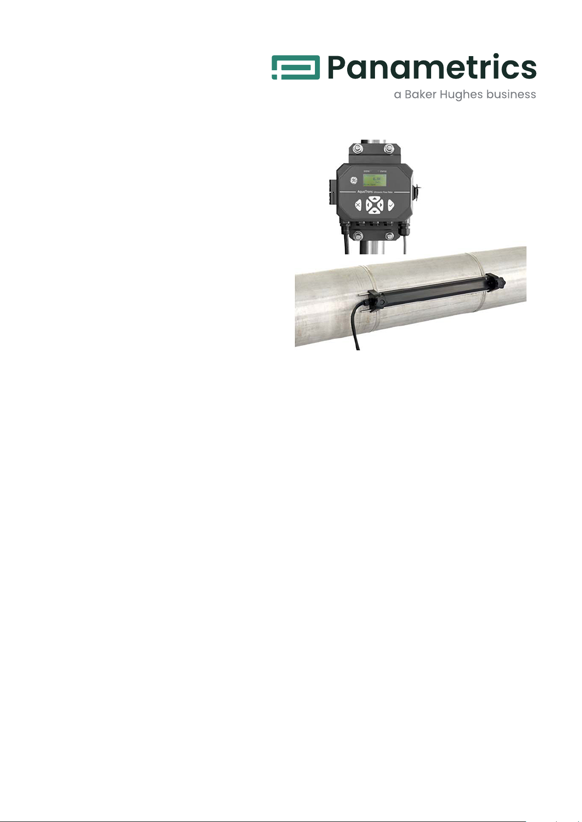
The AquaTrans AT600 liquid flow ultrasonic transmitter
combines state-of-the-art flow measurement
capability with a low-cost transmitter package that can
be installed right at the process measurement point.
It’s designed specifically for water and wastewater
applications in full pipes. The all-digital AquaTrans
AT600 has no moving parts and requires minimal
maintenance. An onboard microprocessor uses
patented Correlation Transit-Time™ technology for
long-term, drift-free operation. Automatic adjustment
to changing fluid properties and dynamically
configured operating software simplify programming.
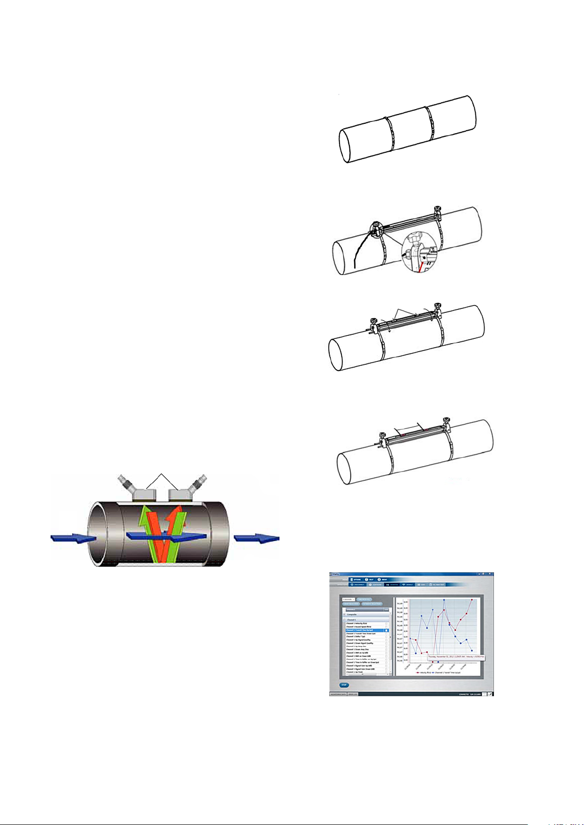
Transit-Time Flow Measurement
In this method, two transducers serve as both ultrasonic
signal generators and receivers. They are in acoustic
communication with each other, meaning the second
transducer can receive ultrasonic signals transmitted
by the first transducer and vice versa.
In operation, each transducer functions as a
transmitter, generating a specified number of acoustic
pulses, and then as a receiver for an identical number
of pulses. The time interval between transmission and
reception of the ultrasonic signals is measured in both
directions. When the liquid in the pipe is not flowing,
the transit-time downstream equals the transit-time
upstream. When the liquid is flowing, the transit- time
downstream is less than the transit-time upstream.
The difference between the downstream and upstream
transit times is proportional to the velocity of the flowing
liquid, and its sign indicates the direction of flow.
Easy Four Step Installation
Step #1: Install straps onto pipe.
Step #2: Put clamp-on fixture on pipe and move straps
onto sides of fixture.
Step #3: Open fixture to set spacing.
Step 4: Set spacing and lock fixture with transducers
onto pipe.
Spacing
Flow Meter Transducers
Fluid
Flow
Ultrasonic Signal Path
Transit-time Flow Measurement Technique
Clamp-On Transducers
Clamp-on transducers oer maximum convenience, exibility
and a low installation cost compared to traditional ow metering
technologies. With proper installation, clamp-on transducers
provide better than 1% of reading accuracy in most applications.
Vitality™ Software (Optional)
The AquaTrans AT600 can communicate with a PC via
our Vitality interface program. Consult the manual for
details on sites, logs, and other operations with a PC.
Page 3

Specifications
Overall Operation and Performance
Fluid Types
Liquids: acoustically conductive fluids, including most
clean liquids, and many liquids with small amounts of
entrained solids or gas bubbles
Flow Measurement
Patented Correlation Transit-TimeTM mode
Pipe Sizes
0.5 to 300 in. (15 to 7600 mm)
Pipe Materials
All metals and most plastics. Consult Baker Huges for
concrete, composite materials, and highly corroded or
lined pipes.
Accuracy
• ±1% of reading in application, ≥2 in. (50 mm) pipe
and >1 ft/s (0.3 m/s) velocity
• ±2% of reading in application, <2 in. (50 mm) pipe
and >1 ft/s (0.3 m/s) velocity
• ±0.5% in field calibration
Installation assumes a fully developed, symmetrical flow
profile (typically 10 diameters upstream and 5 diameters
downstream of straight pipe run). Final installation
accuracy is a function of multiple factors including fluid,
temperature range, pipe centricity and others.
Calibration
All meters are water calibrated and delivered with a
traceable calibration certificate.
Repeatability
±0.2% of reading
Range (Bidirectional)
-40 to 40 ft/s (-12.19 to 12.19 m/s)
Rangability (Overall)
400:1
Measurement Parameters
Velocity, Volumetric, and Totalized Flow
Electronics
Enclosure
Epoxy-coated aluminum weatherproof
Type 4X/IP67
Dimensions
6.6 x 5.0 x 2.4 in. (168 x 128 x 61 mm)
Weight: 3.5 lb/1.5 kg
Channels
One channel
Display
Graphic LCD (128 x 64 pixels)
Keypad
Six-button keypad for full functionality operation
Error Display Indicator
Green or red light
Power Supplies
• Standard: 85 to 265 VAC, 50/60 Hz
• Optional: 12 to 28 VDC, ± 5%
Power Consumption
10 Watts in-rush
5 Watts normal operation
Operating Temperature
-4°F to 131°F (–20°C to 55°C)
Storage Temperature
–40°F to 158°F (–40°C to 70°C)
Outputs (Based on Configuration)
• 4-20 mA (24VDC powered, 600Ω maximum load,
1500 VDC isolation)
• Frequency, Pulse, Alarm (Passive output, 100 VDC,
1 A/1 W maximum, 1500 VDC isolation)
• HART (FSK modulation, Category Flow, Protocol
Version 7.5, Device Revision 2, MFG ID 157, Device
Type Code 127, Number of device variables 34)
• Modbus/RS485 (Half-duplex, 1500 VDC isolation)
Note: Analog outputs are Namur NE43 compliant.
Certification
CE, UL, CSA, (MCert approval pending)
Clamp-On Ultrasonic Flow
Transducers
Temperature Ranges
• Standard: -40 to 302°F (-40 to 150°C)
• Optional: -328 to 752°F (-200 to 400°C)
See specific transducer for exact temperature range.
Mounting Fixture
Anodized aluminum with stainless steel strapping
Couplant
Standard: Solid couplant
Optional: Liquid couplant
Rating
Standard: General purpose (IP66 or IP68)
Note: See specific transducer model for exact rating.
Page 4

Ordering Information
A B C D E F G H I J K L
AT6
C1
AT05
AT10
AT20
UTX40
CFLP
CR05
CR10
CR05SUB
CR10SUB
CR05JB
CR10JB
CP05JB
CP10JB
CP20JB
< >
IN
MM
1
2
3
4
7
1
2
A
H
M
Model:
Clamp-on liquid ultrasonic flow meter cocsisting of an AT600, transducers,
clamping fixture, transducer cable and coupling
Clamp-On System:
Single-channel clamp-on system
Transducer System:
AT05: C-AT transducers, 0.5 MHz, IP68, 12 in./300 mm or greater typ., Tprocess:
-40 to 150°C
AT10: C-AT transducers, 1 MHz, IP68, 4 to 24 in./100 to 600 mm typ., Tprocess:
-40 to 150°C
AT20: C-AT transducers, 2 MHz, IP68, 2 to 6 in./50 to 150 mm typ., Tprocess: -40
to 150°C
UTX40: UTXDR transducers, 4 MHz, IP67, 0.5 to 2in/15 to 50 mm, Tprocess: -20
to 120°C
CFLP: CF-LP transducers, 4 MHz, IP66, 0.5 to 2 in./15 to 50 mm, Tprocess: -40 to
230°C
CR05: C-RS transducers, 0.5 MHz, IP66, 12 i.n/300 mm or greater typ., Tprocess:
-40 to 150°C
CR10: C-RS transducers, 1 MHz, IP66, 4 to 24 in./100 to 600 mm typ., Tprocess:
-40 to 150°C
CR05SUB: C-RS submersible transducers, 0.5 MHz, IP68, 12 in./300 mm or
greater typical, Tprocess: -40 to 150°C
CR10SUB: C-RS submersible transducers, 1 MHz, IP68, 4 to 24 in./100 to 600 mm
typ., Tprocess: -40 to 150°C
CR05JB: C-RS with junction box transducers, 0.5 MHz, IP66, 12 in./300 mm or
greater typ., Tprocess: -40 to 150°C
CR10JB: C-RS with junction box transducers, 1 MHz, IP66, 4 to 24 in./100 to 600
mm typ., Tprocess: -40 to 150°C
CP05JB: C-PT with junction box transducers, 0.5 MHz, IP66, 12 i.n/300 mm or
greater typ., Tprocess: -20 to 210°C
CP10JB: C-PT with junction box transducers, 1 MHz, IP66, 4 to 24 in./100 to 600
mm typ., Tprocess: -20 to 210°C
CP20JB: C-PT with junction box transducers, 2 MHz, IP66, 2 to 6 in./50 to 150
mm typ., Tprocess: -20 to 210°C
Pipe Size:
Nominal outside diameter
Pipe Units:
Inches
Millimeters
Cable Length:
10 ft (3 m) of transducer cable
25 ft (7.5 m) of transducer cable
50 ft (15 m) of transducer cable
100 ft (30 m) of transducer cable
300 ft (90 m) of transducer cable
AT Power:
85 to 265 VAC
12 to 28 VDC
Analog and Digital Output:
4-20 mA analog output only
4-20 mA output with HART
4-20 mA output and Modbus
Page 5

A B C D E F G H I J K L
AA
AF
AT
FF
FT
TT
01
02
03
04
05
06
07
08
09
M
E
Discrete Output:
Two alarm contacts
One alarm contact and one frequency output
One alarm contact and one totalizer (pulse) output
Two frequency outputs
One frequency output and one totalizer (pulse) output
Two totalizer (pulse) outputs
Language:
English
German
French
Italian
Spanish
Portuguese
Russian
Japanese
Chinese
Default Units:
Metric
English
Special:
0
No specials
S
Special
AT6- C1 –AT05 – 5 - IN - 1 - 2 - A- AA- 01- M- 0 (Example Part Number)
Page 6

Panametrics.com
Copyright 2020. Baker Hughes Company. This material contains one
or more registered trademark of Baker Hughes Company and its
subsidiaries in one or more countries. All third-party product and
company names are trademarks of their respective holders.
920-653E
 Loading...