

Page 1
air.IQ
Moisture Analyzer
Packaged Solution
Features
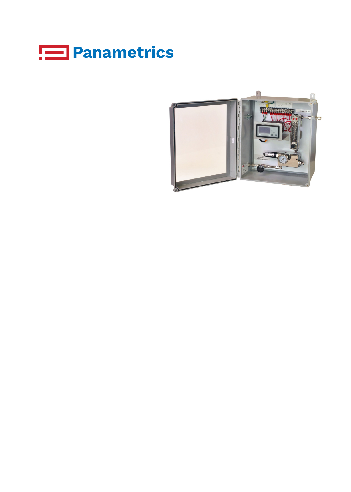
air.IQ simplies the selection and installation
of your moisture analyzer. Install the moisture
probe, wire your power and outputs to the
terminal strip, and connect your gas to the inlet
tting.
• Wall mounted NEMA 4X package
• Includes the analyzer display, moisture
probe, interconnecting cable, and sample
system
• Features the dew.IQ moisture analyzer
• Available with the IQ.probe or with the M
Series moisture probe
• Sample system provides isolation, ltration,
pressure and ow indication, pre-wired, and
a clear door for easy viewing of all readings
Applications
The standard air.IQ package is designed
for moisture measurement in any inert gas
application, in industrial environments classied
as safe areas, where the process gas pressure
is slightly positive to a maximum of 200 psig. It
combines the Panametrics dew.IQ and IQ.probe
with 50 years of sample system design, to deliver
the moisture measurement you have come to
trust.
Markets and applications served include:
• Industrial Gas
• Air Dryer / Clean Dry Air
• Plastics Drying
• Pharmaceutical
• Aerospace
Panametrics.com
• Power Generation
Page 2

Ordering Conguration
air.IQ is comprised of the following items:
• DEW.IQ-3-6-1-0
Datalogger
32 GB capacity with MicroSD card, 2 GB card included
Display
128 x 64 matrix LCD
• IQ.PROBE-2-R-0-0-0-0
• 733-1155-00
Application Parameters
• Inert Gases such as air, nitrogen, SF6
• Sample Gas Pressure: 0 to 200 psig
• Sample Gas Temperature: 0 to +50 C
• Moisture Content: -110 to +20 C dew/frost point,
non-condensing
• Power Requirements: 100 - 240 VAC @ 50 - 60 Hz
*
dew.IQ Specications
European Certication
Complies with EMC Directive 2004/108/EC and
2006/95/EC Low Voltage Directive (Installation
Category II, Pollution Degree II)
Input
Moisture signal from an M Series probe or
IQ.probe
Display Functions
Dew point temperature in °F or °C, ppmv with a constant
pressure input, or sensor signals for diagnostics
Power Requirements
Universal power 100-240 VAC @ 50-60 Hz,
Temperature
• Operating: –20° to 60°C (–4° to 140°F)
• Storage: –40° to 70°C (–40° to 158°F)
Warm-Up Time
Meets specied accuracy within three minutes
*
IQ.probe Specications
Sensor Type
Thin-lm aluminum oxide
Dew/Frost Point Temperature
Overall range capability: –110° to 60°C (–166° to 140°F)
Standard: –80° to 20°C (–112° to 68°F) with data to
–110°C (–166°F)
Analog Output
Single internal isolated recorder output, internally
optically isolated, 10-bit (0.1%) resolution
Switch-Selectable Outputs
0 to 2 V, 10k Ω minimum load resistance
0 to 20 mA, 400 Ω maximum series resistance
4 to 20 mA, 400 Ω maximum series resistance
User-programmable within the range of the instrument
and the corresponding sensor or transmitter
Alarm Relays
One fail-safe fault relay
Two standard Form C relays SPDT, rated for 3 A at 250
VAC/30 VDC
Set to any level within the range of the instrument;
programmable from the front panel
Alarm Set Point Repeatability
±0.2°F (±0.1°C) dew point
Calibrated Accuracy at 77°F (25°C)
• ±3.6°F (±2°C) above -148°F (–100°C)
• ±5.4°F (±3°C) below -148°F (-100°C)
Repeatability
• ±0.4°F (±0.2°C) above -148°F (–100°C)
• ±0.9°F (±0.5°C) below -148°F (–100°C)
* Refer to dew.IQ and IQ.probe data sheets for complete specication details
Page 3

Start-Up Procedure
Shut-Down Procedure
• Insert moisture probe into the sample cell
• Start with the inlet valve and the valve on
rotameter fully closed
• For dew points at process pressure, slowly open
the inlet valve until fully open; then crack the valve
on the rotameter to get ow on scale
• For dew points at atmospheric pressure, fully
open the valve on the rotameter; then crack the
inlet needle valve on the rotameter to get ow on
scale
• Slowly close the inlet needle valve
• Slowly open the valve on the rotameter until the
pressure on the pressure gauge is 0 psig
• Remove the moisture probe
Page 4

MODEL NO.
RN
C
AUTOCAD
GE Sensing
1100 Technology Park Dr.
Billerica, MA 01821 USA
4 5 6 7 8 9 10 11 12 13 14 15
+ - NC C NO NC C NO NC C NO
ALARM
B
ALARM
A
ALARM
FAULTANALOG
OUTPUT
N
L2
L1
100-240 VAC
50-60 Hz, 5W
1 2 34567 8 9 10 11 12 13 14 15
N
L2
L1
100-240 VAC
50-60 Hz, 5W
4 5 6 7 8 9 10 11 12 13 14 15
+ - NC C NO NC C NO NC C NO
ALARM
B
ALARM
A
ALARM
FAULTANALOG
OUTPUT
Page 5

MODEL NO.
DWG
REV
BM
GE Sensing
DRAWN
APPROVED
ITEM
1100 Technology Park Drive,
Billerica, MA 01821,
USA
SALES P/N
PART NO.
481-5521 1
JR 10/25/12 TK 10/25/12
CHECKED
EJ 10/25/12
Needle valve, 5000 psig, 316 SS, 1/4" compression fittings
RELEASE NO.
DESCRIPTION
SAMPLE SYSTEM
BILL OF MATERIALS
BM733-1155-00
SHEET 1 OF 1
QTY PER ASSY (GP)
-01
2
2
3
7 1
421-1466 1
410-485 1
255-165 1
421-1468 1
255-160-02 1
463-002
440-023
410-548 1
255-161-02 1
443-199 1
255-161-03 2
418-061 2
HOUSING, SS880 SAMPLE SYSTEM
CAP PLUG RED 3/4-16X1/2"
PIPE PLUG 1/8 NPTF 316 SS
PLUG, SS880 SAMPLE SYSTEM
Connector 316 SS, 1/4" compression fitting, 1/8" MNPT
FILTER SUPPORT CORE GAS/LIQUID
Filter element, borosilicate microfiber (replacement for 440-024 filter coalescer)
O-RING 1.049ID 0.103THK VT/FKM
Elbow 316 SS, 1/4" compression fittings, 1/8" MNPT
Flowmeter assy, 200 psig, integral inlet flow control valve 2 to 20 SCFH/54 to 540 SLPH, 1/4" compression fittings
Elbow 316 SS, 1/4" compression fittings, 1/4" MNPT
Bracket, Type AA, 3/4" Hole
1-1/2" pressure gauge, 316 SS, 1/8" NPTM center back mount, range 0-300 psig
10-640-3444 1
Assembly mounting and piping of sample system components onto a white-enamel painted steel plate, 12.75" x 10.88"
2002-1245 1
NEMA 4X Enclosure, Fiberglass, 14.55"H x 12.55"W x 8"D
604-5246 1
Mounting of DEW.IQ on a sample system plate, DEW.IQ should be specified, priced and ordered as a separate item.
Mounting Bracket
002-8148 1
1
1
9
11
REV ECN NO.
1 N/A
2 N/A
213-2000 1
213-2001 1
442-1036 1
442-1345 1
DATE/APPD
10/25/2012
12/6/2012
Terminal Strip 15 Position
Terminal Strip Cover
Bulkhead, Union, 316 SS, 1/4" compression fittings
40-361-55201 2
Label, Output
Label, Power Strip
Sample Inlet Label
7431-24421 1
Sub Component Label
5531-24431 1
Union, Explosionproof, conduit to conduit fitting, 1/2" NPTM TO 1/2" NPTF, CL 1, DIV 1 & 2, Grp A,B,C & D
743-55241 1
1/2' Conduit Locknut
8202-21451 1
Gasket, PVC, Self Retaining, with steel ring, 3/8" to 1/2"
10-615-01461 1
Spacer, Threaded, Aluminum, 6-32, 1/4"
045-31471 2
REV
DATE/APPD
NOTES
DPPA/ETADVER.ON NCE
1. REF DWG 733-1155rev2
2. PROCESS CONNS: 1/4" COMPRESSION FITTINGS
3. PROCESS TUBING: 1/4" STAINLESS STEELTUBING
4. ELECTRICAL CONN: 1/2" NPTF
Page 6

C
FAULTANALOG
ALARM
A
ALARM
B
ALARM
OUTPUT
+ - NC C NO NC C NO NC C NO
4 5 6 7 8 9 10 11 12 13 14 15
N
L2
L1
100-240 VAC
50-60 Hz, 5W
Copyright 2019 Baker Hughes, a GE company, LLC (“BHGE”).
Panametrics and logo are registered trademarks of BHGE
in the United States and other countries. All product and
company names are trademarks of their respective holders.
920-624C
 Loading...