

Page 1
GV-IPCam H.264
Hardware Manual
Pinhole Camera
Before attempting to connect or operate this product,
please read these instructions carefully and save this manual for future use.
ICH264TG2V10
Page 2

© 2015 GeoVision, Inc. All rights reserved.
Under the copyright laws, this manual may not be copied, in whole or in
part, without the written consent of GeoVision.
Every effort has been made to ensure that the information in this manual is
accurate. GeoVision, Inc. makes no expressed or implied warranty of any
kind and assumes no responsibility for errors or omissions. No liability is
assumed for incidental or consequential damages arising from the use of
the information or products contained herein. Features and specifications
are subject to change without notice. Note: no memory card slot or local
storage function for Argentina.
GeoVision, Inc.
9F, No. 246, Sec. 1, Neihu Rd.,
Neihu District, Taipei, Taiwan
Tel: +886-2-8797-8377
Fax: +886-2-8797-8335
http://www.geovision.com.tw
Trademarks used in this manual: GeoVision, the GeoVision logo and GV
series products are trademarks of GeoVision, Inc. Windows and Windows
XP are registered trademarks of Microsoft Corporation.
September 2015
Page 3

Page 4

Contents
Contents ..............................................................................i
Options ...............................................................................ii
Chapter 1. Pinhole Camera..............................................1
1.1 Packing List..............................................................................2
1.2 Features...................................................................................3
1.3 Overview .................................................................................. 4
1.4 Installation................................................................................
6
1.5 Connecting the Camera..........................................................
1.6 Loading Factory Default..........................................................
10
11
i
Page 5
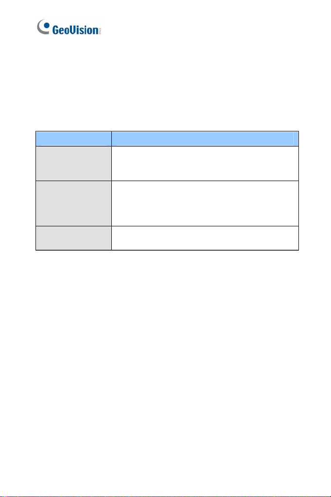
Options
Optional devices can expand your camera’s capabilities and versatility.
Contact your dealer for more information.
Device Description
GV-PA191 PoE
Adapter
GV-POE Switch
10 m (32.8 ft) RJ12 Cable
The GV-PA191 PoE adapter is designed to provide
power and network connection to the cameras
over a single Ethernet cable.
The GV-POE Switch is designed to provide power
along with network connection for IP devices. The
GV-POE Switch is available in various models with
different numbers and types of ports.
A 10 m (32.8 ft) RJ-12 Cable can be purchased to
connect the camera lens and the main body.
ii
Page 6

Pinhole Camera
1
Chapter 1. Pinhole Camera
The Pinhole Camera consists of a main body for processing and a
separate camera lens for capturing images. The compact camera lens can
be installed in surveillance sites with limited space such as behind the
panel of an ATM machine. The Pinhole Camera is also ideal for locations
where discreet surveillance is desirable, such as at the banks, hotels,
museums, stores, and offices.
Model No. Specification Description
GV-UNP2500
Fixed
Lens
Fixed Iris, f:3.7 mm,
F/2.8, 1/2.7” M12
mount
2 MP Super Low
Lux, H.264, D/N,
Pinhole Camera
1
Page 7

1.1 Packing List
Pinhole Camera 1 m (3.28 ft) RJ-12 Cable
Camera Adhesive Tape x 2
Main Body Mount
M3 Screw x 2
GV-IPCAM H.264 Software
DVD
Warranty Card
Installation Sticker
Main Body Adhesive Tape
M2 Screw
GV-NVR Software DVD
2
Page 8

Pinhole Camera
1
1.2 Features
1/2.8" progressive scan super low lux CMOS
Dual streams from H.264 or MJPEG
Up to 30 fps at 1920 x 1080
Megapixel lens
Day and night function (electronic)
Micro SD card slot (SD/SDHC) for local storage
NAS recording
Recording assigned by GV-Edge Recording Manager (Windows &
Mac)
One-way audio
3D DNR (Digital Noise Reduction)
Wide Dynamic Range (WDR)
Defog
Motion detection
Tampering alarm
Visual automation
Text overlay
Privacy mask
IP address filtering
PoE (IEEE 802.3af)
Support for iPhone, iPad, Android and 3GPP
31 languages on Web interface
ONVIF (Profile S) conformant
3
Page 9

1.3 Overview
Camera Lens
1
2
Main Body
4
5
3
6
7
8
Figure 1-1
4
9
No. Name Description
1 Lens Receives images.
2 Microphone Receives sounds.
3 Lens Screw Loosens to adjust the camera lens.
4 RJ12 Port
4
Use the supplied RJ12 cable to connect the
camera lens and main body.
Page 10

Pinhole Camera
1
No. Name Description
RJ12 Status
5
LED
6 PoE Connects to a PoE adapter.
7 Status LED Turns on (green) when the system is ready.
Memory Card
8
Slot
9 Default Button
Turns on (green) when the camera lens and
main body are connected.
Inserts a micro SD ca r d (SD/SDHC, ve r sion
2.0, Class 10) to store recording data.
Restores the camera to factory default. For
details, see 1.6 Loading Factory Default.
5
Page 11

1.4 Installation
The Pinhole Camera is designed for indoors. You can install the camera
lens behind a wall or the ceiling board. Note that the thickness of the wall
or ceiling board must be under 4 mm.
Figure 1-2
1. Paste the installation sticker on the ceiling or the wall where you want
to install the camera lens.
2. Drill a hole 9 mm in diameter. Be sure to remove the sticker after you
finish drilling.
Figure 1-3
6
Page 12

Pinhole Camera
1
Paste one of the supplied camera adhesive tapes onto the camera
3.
lens.
Figure 1-4
4. Remove the backing paper on the other side of the adhesive tape and
attach the camera lens onto the wall or ceiling. The arrows on the
camera lens point toward the top of the camera view.
Figure 1-5
7
Page 13

5. Loosen the lens screw and adjust the position of the lens so that the
metal ring is pressing against the wall or ceiling.
Metal ring
Lens screw
Figure 1-6
6. Place the main body mount where you want to install it, and secure
the mount using one of the methods below.
Insert and tighten the two supplied M3 screws.
Figure 1-7
Paste the main body adhesive tape on the bottom side of the
main body mount.
Figure 1-8
8
Page 14

Pinhole Camera
1
Align the main body with the mount as shown below and secure with
7.
the supplied M2 screw.
Figure 1-9
8. Connect the camera lens and the main body using the RJ-12 cable.
9. Connect the main body to the network and supply power via the PoE
cable. See 1.4 Connecting the Camera.
10. Access the live view. See 2.1 Accessing the Live View, GV-IPCam
H.264 Firmware Manual.
9
Page 15

1.5 Connecting the Camera
1. Use the supplied RJ12 cable to connect the camera lens and the
main body.
Figure 1-10
2. Use a Power over Ethernet (PoE) adapter to connect the camera to
the network, and the power will be provided over the network cable.
Status LED
Figure 1-11
The status LED of the camera will be on.
10
Page 16

Pinhole Camera
1
1.6 Loading Factory Default
1. Keep the PoE cable connected to the main body.
2. Use a pin to press and hold the Load default button on the panel.
Status LED
Load Default
3. Release the default button when the status LED blinks. This shall
take about 8 seconds.
4. When the status LED fades, the process of loadi ng default s ett i ngs is
completed and the camera reboots automatically.
Figure 1-12
11
 Loading...