

Page 1
GV-IP Camera
User's Manual
GV-EBD Series
GV-ABL / TBL Series
GV-ADR / TDR Series
GV-AVD / TVD Series
Before attempting to connect or operate this product,
please read these instructions carefully and save this manual for future use.
UBN-UM-Q
Page 2
© 2020 GeoVision, Inc. All rights reserved.
Under the copyright laws, this manual may not be copied, in whole or in part,
without the written consent of GeoVision.
Every effort has been made to ensure that the information in this manual is
accurate. GeoVision, Inc. makes no expressed or implied warranty of any kind
and assumes no responsibility for errors or omissions. No liability is assumed
for incidental or consequential damages arising from the use of the information
or products contained herein. Features and specifications are subject to
change without notice.
Note: No memory card slot or local storage function for Argentina.
GeoVision, Inc.
9F, No. 246, Sec. 1, Neihu Rd.,
Neihu District, Taipei, Taiwan
el: +886-2-8797-8377
T
Fax: +886-2-8797-8335
http://www.geovision.com.tw
Trademarks used in this manual: GeoVision, the GeoVision logo and GV
series products are trademarks of GeoVision, Inc. Windows is the registered
trademark of Microsoft Corporation.
August 2020
Page 3
Preface
Welcome to the GV-EBD Series IR Eyeball IP Dome, GV-ABL Series Bullet IP Camera,
GV-ADR / TDR Series Mini Fixed Rugged IP Dome and GV-AVD Series Vandal Proof IP
Camera User’s Manual.
The features described in the manual vary among camera models and versions. Some
features may not be available in your camera.
This Manual is designed for the following models:
Model Model Number
GV-EBD2702
IR Eyeball Dome
Bullet IP Camera
Mini Fixed Rugged IP Dome
Vandal Proof IP Dome
GV-EBD4700 / 4711
GV-EBD8700 / 8711
GV-ABL2701 Series / 2702 / 2703 Series
GV-ABL4701 Series / 4703 / 4712
GV-ABL8712
GV-TBL2703 Series / 4700 / 4703 / 4710 / 4711
GV-TBL8710
GV-ADR2701 / 2702
GV-ADR4701 / 4702
GV-TDR2700 / 2702
GV-TDR4700 Series / 4702
GV-AVD2700
GV-AVD4710
GV-AVD8710
GV-TVD4700
GV-TVD4710 / 4711
GV-TVD8710
i
Page 4

Contents
Naming Definition....................................................................vi
Note for Connecting to GV-VMS / DVR / NVR......................vii
Note for Installing Camera Outdoor .....................................vii
Note for Powering the Camera..............................................vii
Note for Face Detection........................................................viii
Note for People Counting.......................................................ix
Chapter 1 Introduction ..........................................................1
1.1 GV-EBD Series...................................................................................................... 1
1.1.1 Packing List................................................................................................ 2
1.1.2 Optional Accessories ................................................................................. 2
1.1.3 Overview.................................................................................................... 4
1.1.3.1 GV-EBD2702 / 4700 / 8700..................................................................... 4
1.1.3.2 GV-EBD4711 / 8711 ............................................................................... 5
1.1.4 Installation.................................................................................................. 6
1.1.4.1 GV-EBD 2702 / 4700 / 8700 St andard Installation......................... 6
1.1.4.2 GV-EBD 4711 / 8711 Standa rd Installation.................................... 9
1.1.5 Optional Installation...................................................................................12
1.1.5.1 GV-Mount211P............................................................................12
1.1.5.2 GV-Mount212P............................................................................17
1.1.5.3 GV-Mount420 + GV-Mount211P..................................................21
1.1.5.4 GV-Mount212P + GV-Mount107..................................................24
1.2 GV-ABL / TBL Series............................................................................................26
1.2.1 Packing List...............................................................................................27
1.2.2 Optional Accessories ................................................................................27
1.2.3 Overview...................................................................................................28
1.2.3.1 GV-ABL2701 / 2703 / 4701 / 4703 & TBL2703 / 4703..................28
1.2.3.2 GV-ABL2702 / 4712 / 8712 & TBL4700 / 4710 / 4711 / 8710.......29
1.2.4 Installation.................................................................................................30
1.2.5 Optional Installation...................................................................................34
1.2.5.1 GV-Mount502..............................................................................35
1.2.5.2 GV-Mount503..............................................................................37
1.2.5.3 GV-Mount420 + GV-Mount503....................................................39
ii
Page 5

1
.3 GV-ADR / TDR Series ..........................................................................................41
1.3.1 Packing List...............................................................................................42
1.3.2 Optional Accessories ................................................................................43
1.3.3 Overview...................................................................................................45
1.3.4 Installation.................................................................................................46
1.3.5 Optional Installation ...........................................................................................49
1.3.5.1 GV-Mount211P......................................................................................49
1.4 GV-AVD / TVD Series...........................................................................................53
1.4.1 Packing List...............................................................................................54
1.4.1.1 GV-TVD4711...............................................................................54
1.4.1.2 GV-AVD / TVD Series..................................................................55
1.4.2 Optional Accessories ................................................................................56
1.4.3 Overview...................................................................................................57
1.4.3.1 GV-AVD2700 / 4710 / 8710, GV-TVD4700 / 4710 / 8710............57
1.4.3.2 GV-TVD4711...............................................................................58
1.4.4 Installation.................................................................................................59
1.4.4.1 GV-AVD2700 / 4710 / 8710, GV-TVD4700 / 4710 / 8710............59
1.4.4.2 GV-TVD4711...............................................................................61
1.4.5 Optional Installation...................................................................................63
1.4.5.1 GV-Mount211-2...........................................................................63
1.4.5.2 GV-Mount212-2...........................................................................66
1.4.5.3 GV-Mount420 + GV-Mount211-2.................................................69
1.4.5.4 GV-Mount606..............................................................................70
1.5 System Requirements...........................................................................................72
1.6 Waterproofing the Cable .......................................................................................73
Chapter 2 Accessing the Camera.......................................75
2.1 Installing on a Network..........................................................................................75
2.1.1 Looking up the Dynamic IP Address and Logging In .................................76
2.1.2 Configuring the IP Address .......................................................................77
2.2 Accessing Live View.............................................................................................78
2.2.1 Digital Zoom..............................................................................................80
2.2.2 Start Recording.........................................................................................80
2.3 Playing Back Recorded Videos.............................................................................81
2.3.1 Recording Download.................................................................................82
iii
Page 6

Chapter 3 Administrator Mode...........................................83
3.1 Common...............................................................................................................85
3.1.1 Basic Info..................................................................................................85
3.1.2 Local Parameters......................................................................................86
3.2 Network ................................................................................................................88
3.2.1 Network.....................................................................................................88
3.2.2 DNS..........................................................................................................89
3.2.3 Port...........................................................................................................90
3.2.4 DDNS........................................................................................................91
3.2.5 E-mail........................................................................................................93
3.2.6 SNMP .......................................................................................................94
3.2.7 802.1x.......................................................................................................95
3.2.8 QoS ..........................................................................................................96
3.3 Video & Audio.......................................................................................................97
3.3.1 Video.........................................................................................................97
3.3.2 Snapshot...................................................................................................99
3.3.3 Audio.......................................................................................................100
3.3.4 ROI.........................................................................................................101
3.3.5 Media Stream..........................................................................................102
3.4 Image .................................................................................................................104
3.4.1 Image......................................................................................................104
3.4.2 OSD........................................................................................................109
3.4.3 Privacy Mask...........................................................................................111
3.5 Intelligent............................................................................................................112
3.5.1 Smart Settings ........................................................................................112
3.5.1.1 Cross Line.................................................................................113
3.5.1.2 Intrusion ....................................................................................115
3.5.1.3 Object Removed........................................................................116
3.5.1.4 Object Left Behind.....................................................................117
3.5.1.5 Defocus.....................................................................................118
3.5.1.6 Scene Change...........................................................................119
3.5.1.7 Face Detect ion ..........................................................................120
3.5.1.8 People Counting........................................................................121
3.5.1.9 Human Body Detection..............................................................122
3.5.2 Advanced Settings..................................................................................123
3.6 Events................................................................................................................124
3.6.1 Motion Detect ion.....................................................................................124
v
iv
Page 7

3.6.2 Tampering Alarm ....................................................................................126
3.6.3 Audio Detection.......................................................................................127
3.6.4 Alarm Input..............................................................................................128
3.6.5 Alarm Output...........................................................................................129
3.7 Formatting Storag e.............................................................................................130
3.7.1 Storage...................................................................................................130
3.7.2 FTP.........................................................................................................132
3.7.3 Backing Up Storage................................................................................133
3.8 Security...............................................................................................................134
3.8.1 User........................................................................................................134
3.8.2 Network Security.....................................................................................135
3.9 System................................................................................................................138
3.9.1 Time........................................................................................................138
3.9.2 Maintenance...........................................................................................140
Chapter 4 Advanced Applications ...................................141
4.1 Upgrading System Fi rmware...............................................................................141
4.1.1 Using the W eb Interface..........................................................................142
4.1.2 Using GV-IP Device Utility.......................................................................143
4.2 Restoring to Factory Default Settings..................................................................144
Chapter 5 DVR / NVR / VMS ..............................................145
5.1 Setting Up IP Cameras on GV-DVR / NVR .........................................................145
5.2 Setting Up IP Cameras on GV-VMS ...................................................................149
Appendix...............................................................................151
A. RTSP Multicast Protocol Support .........................................................................151
B. RTSP Protocol Support........................................................................................151
C. HTTP Protocol Support ........................................................................................151
D. Compatible Versions of GV-VMS / DVR / NVR.....................................................152
E. GV-Mount Dimensions .........................................................................................153
F. GV-Mount300-2 / 310-2........................................................................................156
G. Screw Position Chart............................................................................................159
Page 8
Naming Definition
GV-DVR / NVR
GV-VMS
GeoVision Analog and Digital Video Recording Software. The GVDVR also refers to GV-Multicam System or GV-Hybrid DVR.
GeoVision Video Management System for IP cameras.
vi
Page 9
Note for Connecting to GV-VMS / DVR / NVR
The GV-IPCAM in this Manual is designed to work with and record on GV-VMS / DVR / NVR,
a video management system.
Once the camera is connected to the GV-VMS / DVR / NVR, the resolution set on the
GV-VMS / DVR / NVR will override the resolution set on the camera’s Web interface.
You can only change the resolution settings through the Web interface when the
connection to the GV-VMS / DVR / NVR is interrupted.
The login password of the camera cannot contain the character “&” or any whit espace
when connecting to GV-VMS.
The Video Analytic features under Intelligent (see 3.5 Intelligent) cannot be integrated
with GV-VMS / DVR / NVR.
Note for Installing Camera Outdoor
When installing the camera outdoor, be sure that:
1. The camera is set up above the junction box to prevent water from entering the camera
along the cables.
2. Any PoE, power, audio and I/O cables are waterproofed using waterproof silicon rubber
or the like.
3. The screws are tightened and the cover is in place af ter opening the camer a cover.
Note for Powering the Camera
The camera is powered by PoE or a power adapter. If you want to power the camera using
the power connector, an optional power adapter is required.
vi
i
Page 10
Note for Face Detection
To use the camera’s built-in face detection feature (see 3.5.1.7 Face Detection), not
supported by GV-ABL2701 series / 2703 series / 4701 series / 4703, GV-ADR2701 / 2702 /
4701 / 4702, GV-TBL series, GV-TDR2702 / 4702 and GV-TVD series, it is recommended to
install the camera according to the criteria listed below:
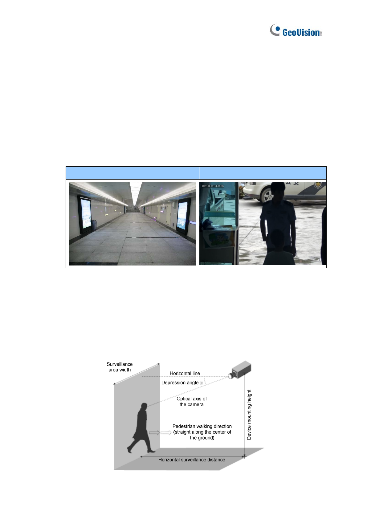
Surveillance Condition
The camera shall be installed at a site with uniform, sufficient lighting, where the
face(s) to be detected are fully illuminated.
Example of Recommended Scene Example of Non-recommended Scene
Camera Position
The camera shall be mounted at a recommended height of 2. 5 ~ 3 m (8.2 ~ 9.84 ft).
The camera shall be mounted with a recommended depression angle of around 10°.
The camera shall be positioned so that the face(s) to be detected are directly aligned
with the lens of the camera, with a horizontal deviation of no greater than 30°, a
vertical deviation of no greater than 15° and a face size of at least 120 pixels.
v
iii
Page 11
Note for People Counting
To use the camera’s built-in people counting feature (see 3.5.1.8 People Counting), not
supported by GV-ABL2701 series / 2703 series / 4701 series / 4703, GV-ADR2701 / 2702 /
4701 / 4702, GV-TBL series, GV-TDR2702 / 4702 and GV-TVD series, it is recommended to
install the camera according to the criteria listed below:
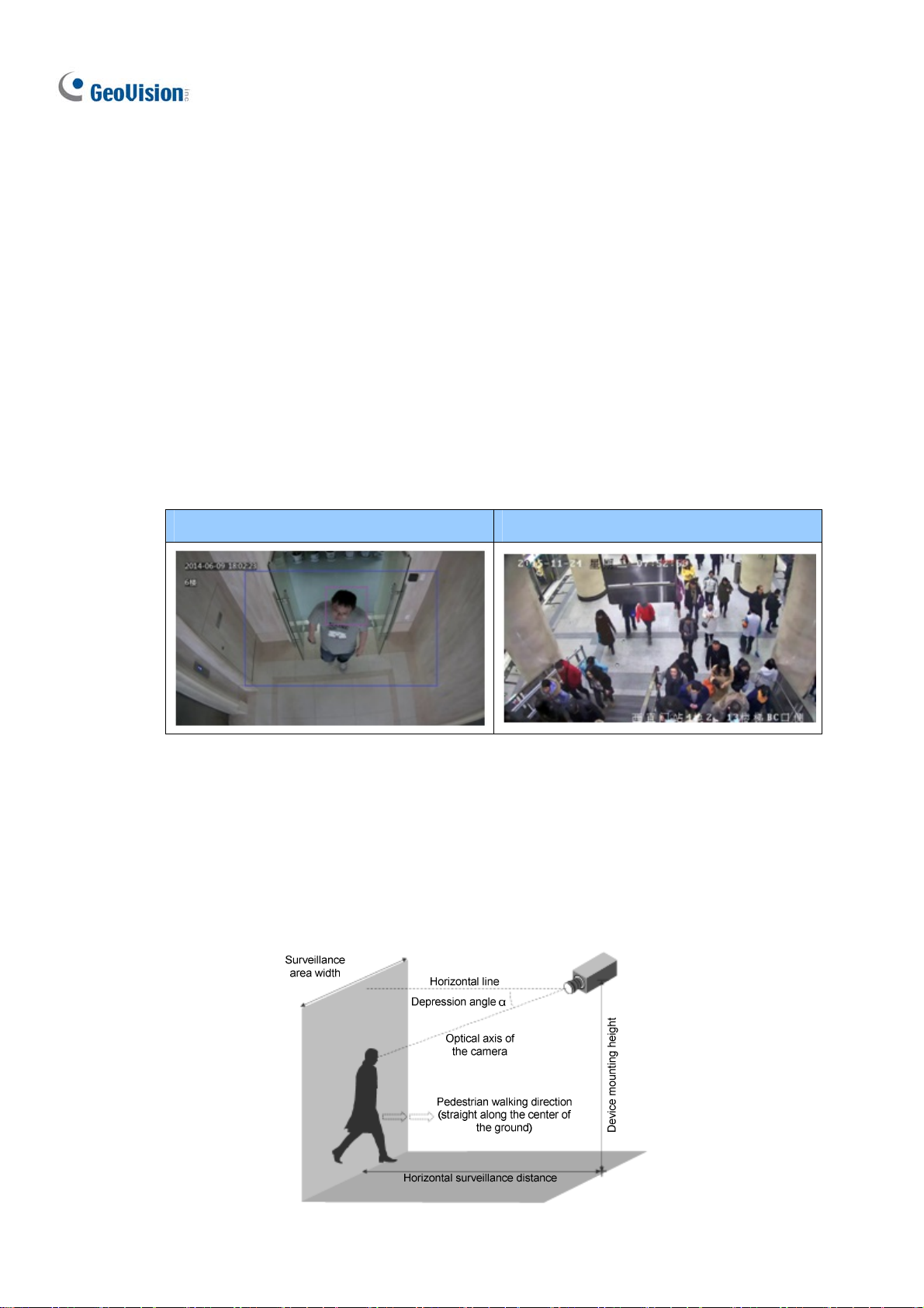
Surveillance Condition
The camera shall be installed at a site with uniform, sufficient lighting, where the
person(s) to be counted are fully illuminated.
The camera shall be installed at an entrance or exit with an ideal width of 1 ~ 4 m
(3.28 ~ 13.12 ft), where the persons(s) to be counted move toward the lens of the
camera in single file.
Example of Recommended Scene Example of Non-recommended Scene
Camera Position
The camera shall be mounted at a recommended height of 3 ~ 5 m (9.84 ~ 16.4 ft).
The camera shall be mounted with a recommended depression angle of 70 ~ 80°.
The camera shall be positioned so that the person(s) to be counted face toward the
lens of the camera and are displayed on the image with a shoulder size of between
120 ~ 160 pixels.
ix
Page 12
Introduction
1
Chapter 1 Introduction
1.1 GV-EBD Series
The H.265 Target Eyeball Dome is an outdoor, network camera equipped with an automatic
IR-cut filter and IR LEDs for day and night surveillance. The camera adheres to IP67
standards for dust / water protection and supports H.265 video codec to achieve better
compression ratio while maintaining high quality image at reduced network bandwidths. With
its WDR Pro (WDR for GV-EBD2702), It can process scenes with contrasting intensity of
lights and produce clear image.
For GV-EBD4711 / 8711, with their motorized lenses, the user can zoom and focus the
camera from the Web interface. The camera also provides built-in micro SD card slot for
local storage.
Model No. Specifications Description
GV-EBD2702
GV-EBD4700
GV-EBD8700
GV-EBD4711
GV-EBD8711
Fixed Iris, f: 2.8 mm,
F/1.8, M12 Lens Mount
Fixed lens
Fixed Iris, f: 2.8 mm,
F/2.0, M12 Lens Mount
Fixed Iris, f: 2.7 ~ 12 mm,
F/1.4, Ø12 mm Lens
Mount
Motorized
varifocal lens
Fixed Iris, f: 2.8 ~ 12 mm
F/1.5, Ø12 mm Lens
Mount
2 MP, H.265,
Low Lux, WDR
4 MP, H.265,
Low Lux, WDR Pro
8 MP, H.265,
Low Lux, WDR Pro
4 MP, H.265,
Low Lux, WDR Pro
8 MP, H.265,
Super Low Lux,
WDR Pro
1
Page 13
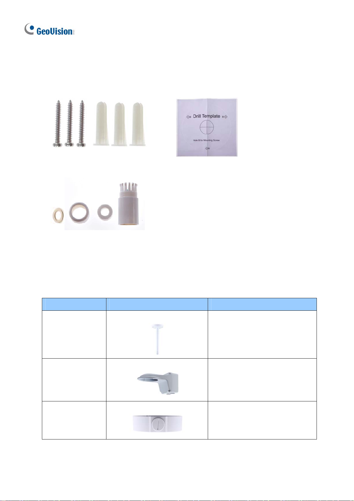
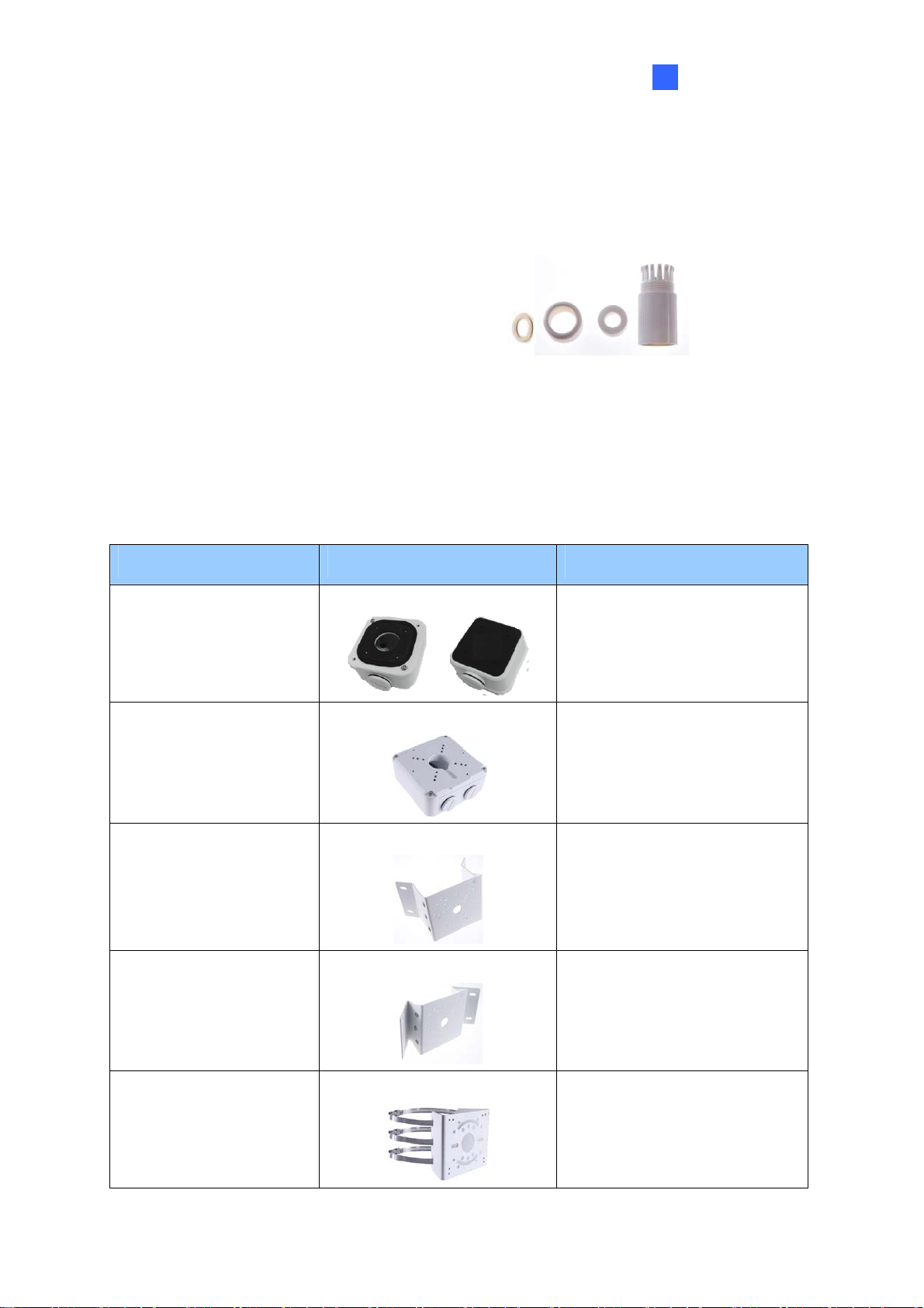
1.1.1 Packing List
H.265 Target Eyeball Dome
Screw Kit
Waterproof Rubber Set
1.1.2 Optional Accessories
Drill Template Paster
Download Guide
Warranty Card
Optional accessories can expand the capabilities and versatility of your camera. Contact your
dealer for more information.
Model Number Name Details
GV-Mount107
(must be used with
GV-Mount212P)
GV-Mount211P Wall Mount and Junction Box
GV-Mount212P Wall Box Mount
Pendant Bracket
Dimensions: Ø 120 x 334 mm (Ø
4.72” x 13.15”)
Weight: 0.74 kg (1.63 lb)
Dimensions: 233 x 126 x 126 mm
(9.2” x 5” x 5”)
Weight: 1 kg (2.2 lb)
Dimensions: Ø 126 x 36 mm (Ø
5.0” x 1.4”)
Weight: 0.22 kg (0.48 lb)
2
Page 14
Introduction
1
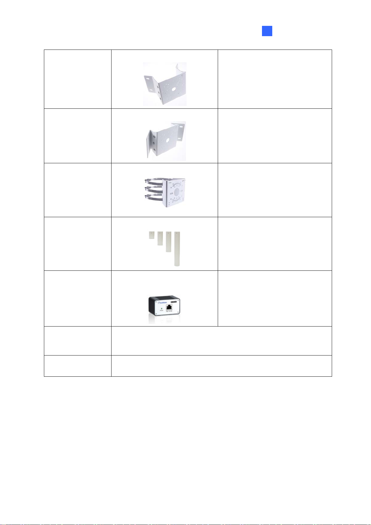
G
V-Mount 300- 2 Convex Corner Mount
GV-Mount310-2 Concave Corner Mount
GV-Mount420
Pole Mount Bracket
(must be used with
GV-Mount211P)
GV-Mount704
Extension Tube
(must be used with
GV-Mount107)
Dimensions: 137 x 233 x 160 mm
(5.4” x 9.17” x 6.3”)
Weight: 1.65 kg (3.64 lb)
Dimensions: 111.2 x 369.9 x 210
mm (2.6” x 11.4” x 6.6”)
Weight: 1.65 kg (3.64 lb)
Dimensions: Ø 120 x 120 x 53.4
mm (Ø 4.7” x 4.7” x 2.1”)
Weight: 0.45 kg (0.99 lb)
Steel Strap Diameter: Ø 67 ~ 127
mm (Ø 2. 6” ~ 5”)
Dimensions: Ø 3.5 x 10 or 20 or 30
or 50 cm (Ø 1.38 x 3.9 or 7.9 or
11.8 or 19.7”)
Weight: 225 g or 360 g or 500 g or
780 g (0.5 lb or 0.79 lb or 1.1 lb or
1.72 lb)
GV-PA191
GV-POE Switch
Power Adapter
Power over Ethernet (PoE)
Adapter
GV-PA191 is a Power over
Ethernet (PoE) adapter designed
to provide power to the IP device
through a single Ethernet cable.
GV-POE Swit ch is designed to provide power along with network
connection for IP devices. GV-POE Switch is available in various
models with different numbers and types of ports.
Contact our sales representatives for the countries and areas
supported.
3
Page 15
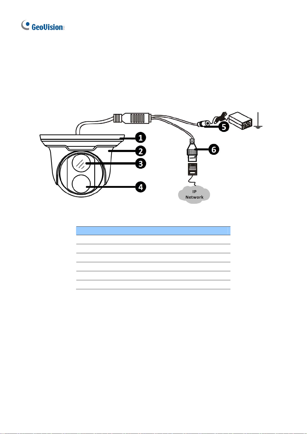
1.1.3 Overview
1.1.3.1 GV-EBD2702 / 4700 / 8700
Figure 1-1
No. Description
1 Bottom ring
2 Housing
3 Lens
4 Infrared indicator
5 Power connector (DC 12 V)
6 Ethernet connector / PoE
4
Page 16
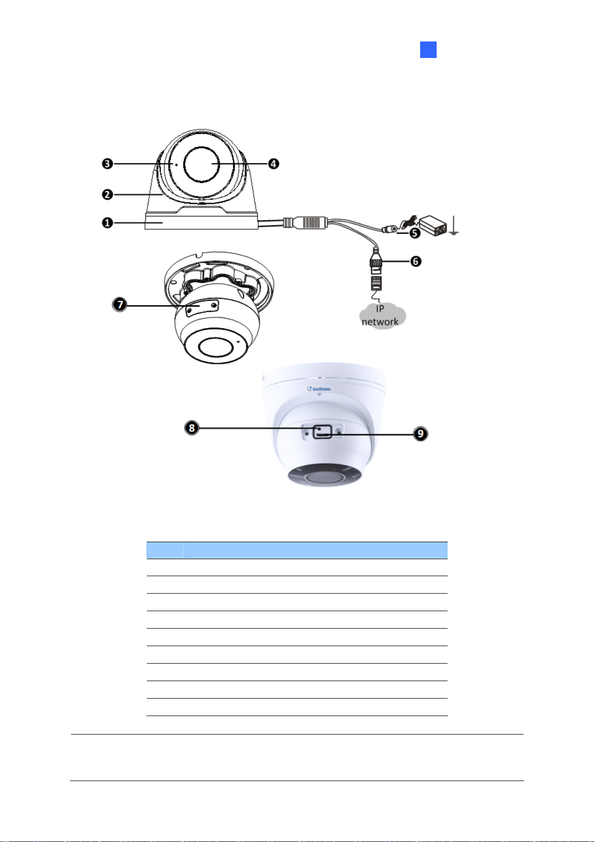
1.1.3.2 GV-EBD4711 / 8711
Introduction
1
Figure 1-2
No. Description
1 Bottom ring
2 Housing
3 Microphone
4 Lens
5 Power connector (DC 12 V)
6 Ethernet connector / PoE
7 Micro SD card slot and default button compartment
8 Default button
9 Micro SD card slot
Note: If the default button doesn’t respond after pressing for 15 seconds, reboot the
camera and try again within 10 minutes of rebooting.
5
Page 17
1.1.4 Installation
The Target Eyeball Dome is designed for outdoors. With the standard package, you can
install the camera on the ceiling. Alternatively, you can purchase optional mounting
accessories to mount the dome on a wall.
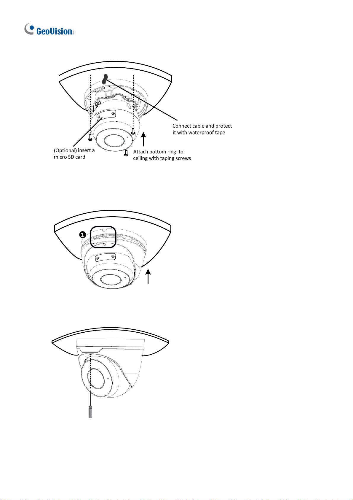
Below are the instructions for Ceiling Mount. There are two kinds of Ceiling Mount:
Concealed Installation and Open Installation. In concealed installation, the cables are
hidden in the ceiling. In Open Installation, the cables are led out from the open slot on the
bottom ring.
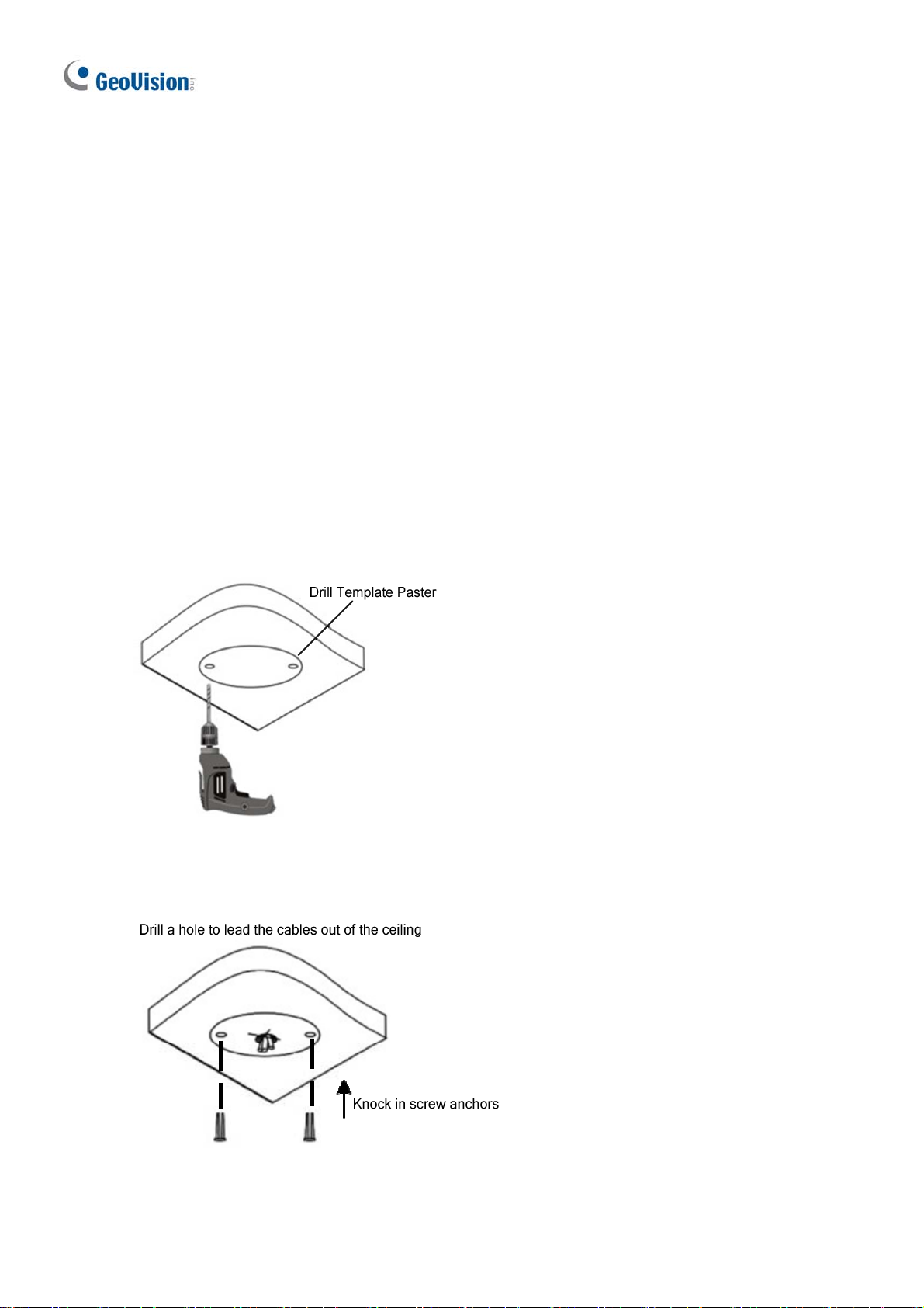
1.1.4.1 GV-EBD2702 / 4700 / 8700 Standard Installation
For Concealed Installation
1. Stick the drill template paster to the ceiling and drill three holes according to the drill
template.
Figure 1-3
2. Insert the screw anchors.
Figure 1-4
6
Page 18
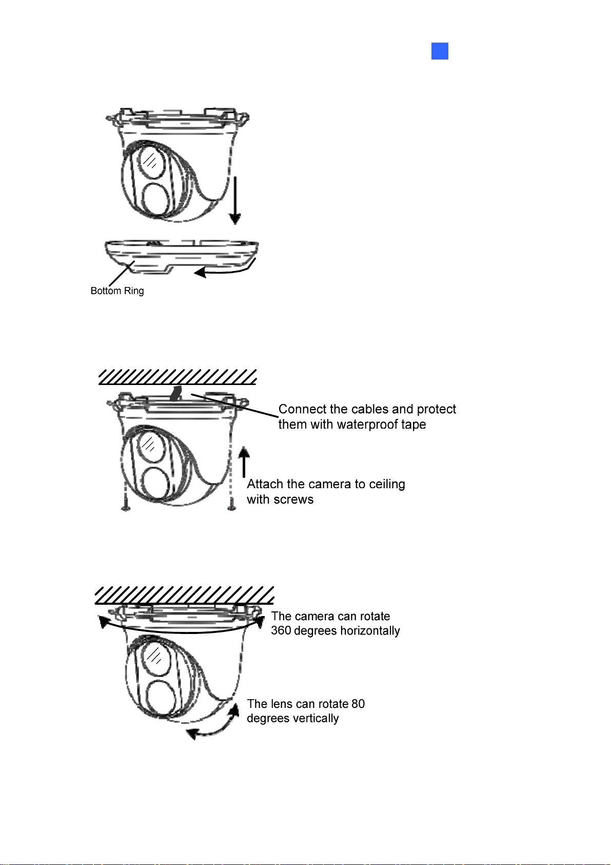
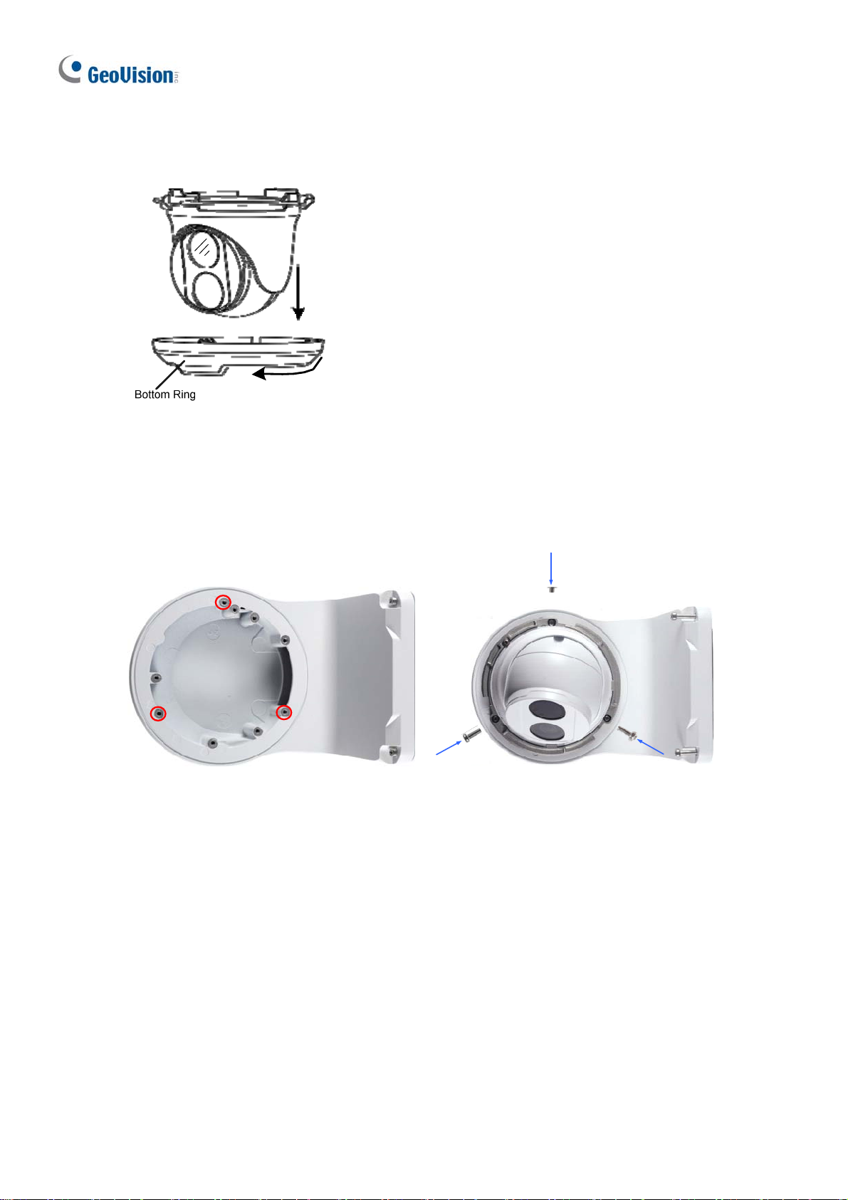
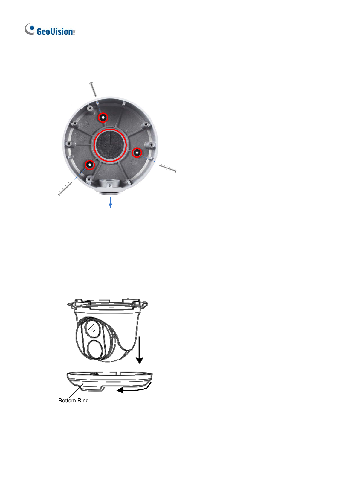
3.
Remove the bottom ring by turning it anticlockwise.
Figure 1-5
Introduction
1
4. Connect the cables and secure the camera.
Figure 1-6
5. Adjust the monitoring direction.
Figure 1-7
7
Page 19
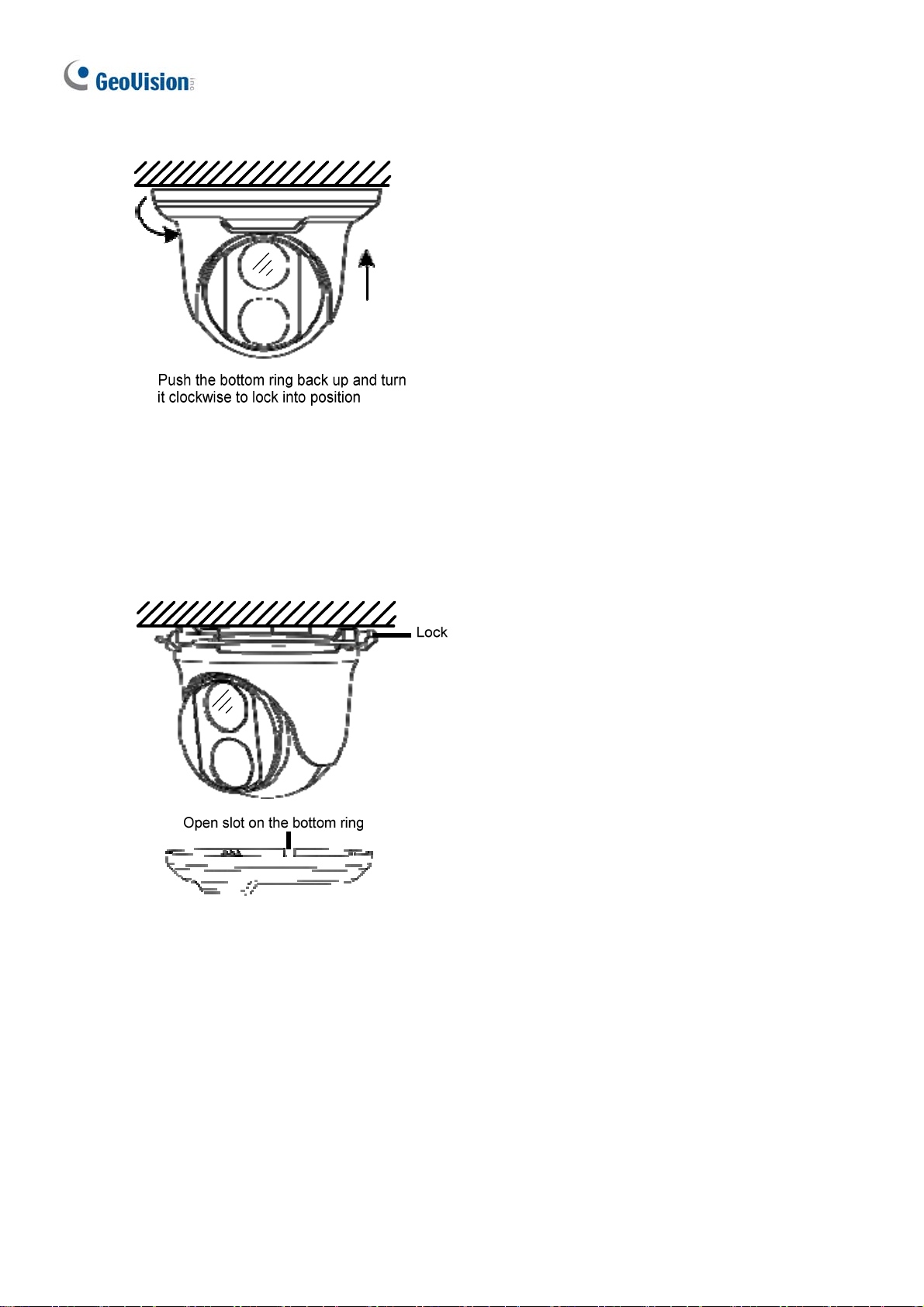
6.
Mount the bottom ring.
Figure 1-8
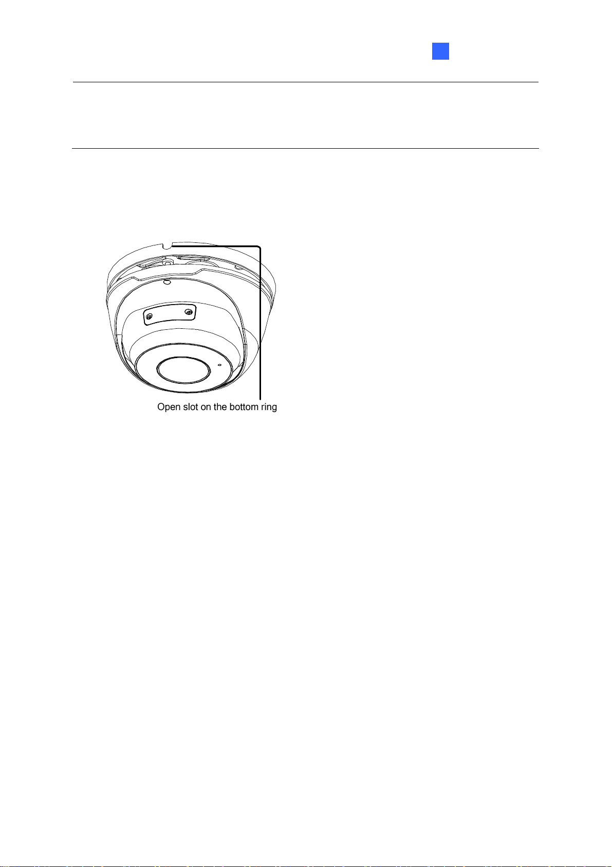
For Open Installation
Lead the cables out from the open slot on the bottom ring before screwing the camera to t he
ceiling as shown in Figure 1-6.
Figure 1-9
8
Page 20
Introduction
1
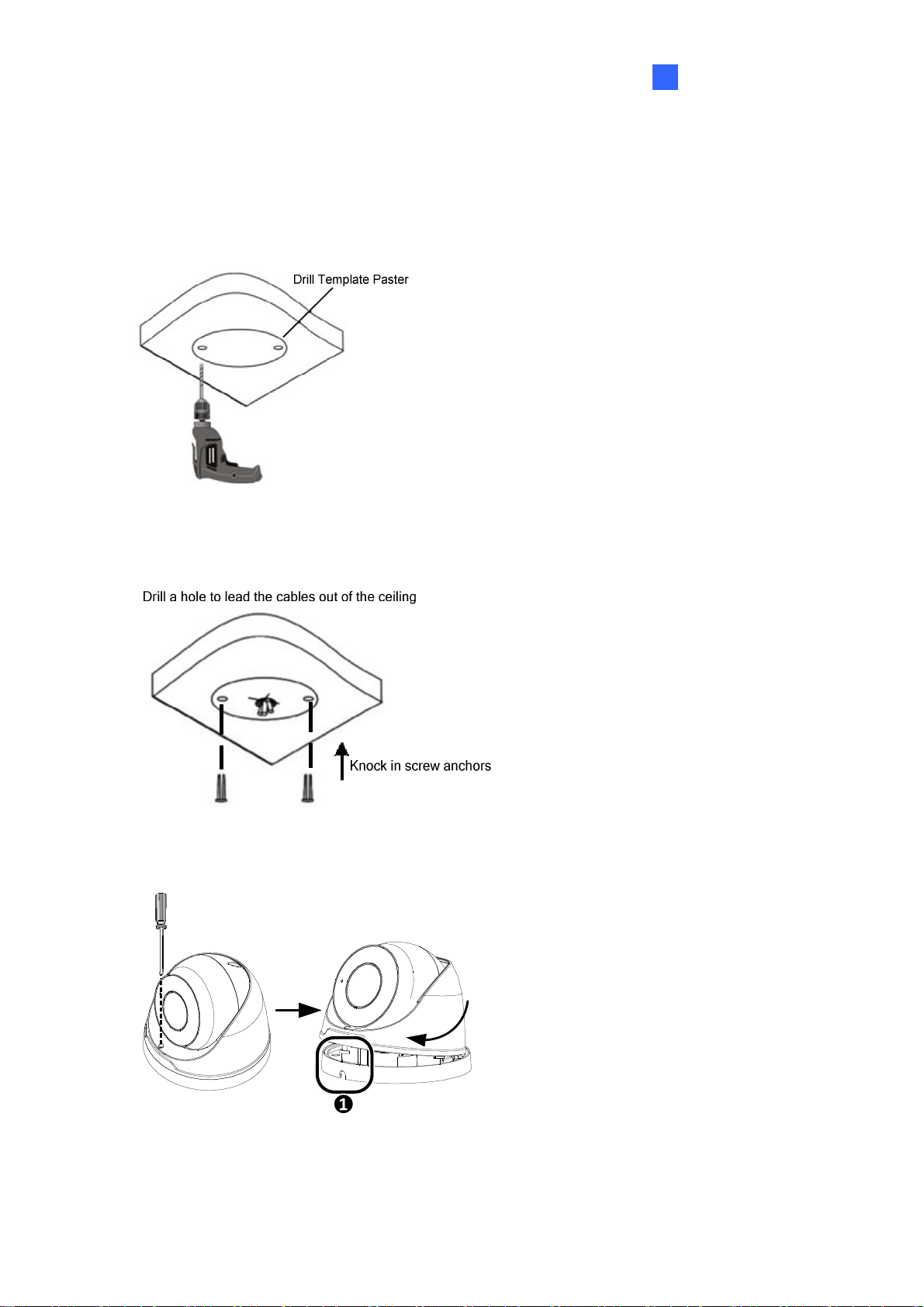
1.1.4.2 GV-EBD4711 / 8711 Standard Installation
For Concealed Installation
1. Stick the drill template paster to the ceiling and drill three holes according to the drill
template.
Figure 1-10
2. Insert the screw anchors.
Figure 1-11
3. Loosen the fixing screw and remove the housing by turning it to the position as shown.
Figure 1-12
9
Page 21
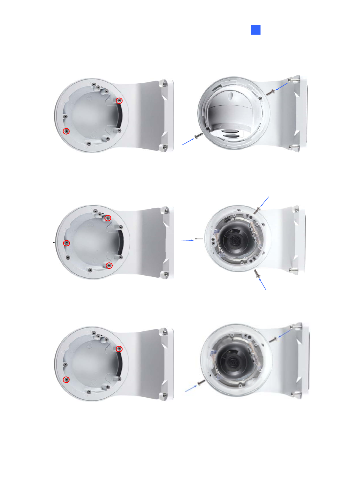
4.
Secure the bottom ring to the ceiling with 3 supplied screws and connect the cable.
Figure 1- 13
5. Mount the housing by adjusting to the position as shown and pr ess and turn to anywhere
but .
Figure 1- 14
6. Adjust the monitoring direction. Then tighten the screw.
Figure 1-15
10
Page 22
Introduction
1
W
ARNING: Make sure the housing is not dismounted from the bottom ring when adjusting
the monitoring direction. Unintentional removal of the housing may result in circumstantial
damages.
For Open Installation
Lead the cables out from the open slot on the bottom ring before mounting t he housing as
shown in Figure 1-14.
Figure 1-16
11
Page 23
1.1.5 Optional Installation
You can optionally purchase the following accessories to fit your mounting environment:
GV-Mount211P / GV-Mount212P for Wall Box Mount: see section 1.1.5.1 and 1.1.5.2.
GV-Mount420 + GV-Mount211P for Pole Box Mount: see section 1.1.5.3.
GV-Mount212P + GV-Mount107 for Pendant Tube Mount: see section 1.1.5.4.
GV-Mount300-2 / 310-2 for Corner Mount: see Appendix F. GV-Mount300-2 / 310-2.
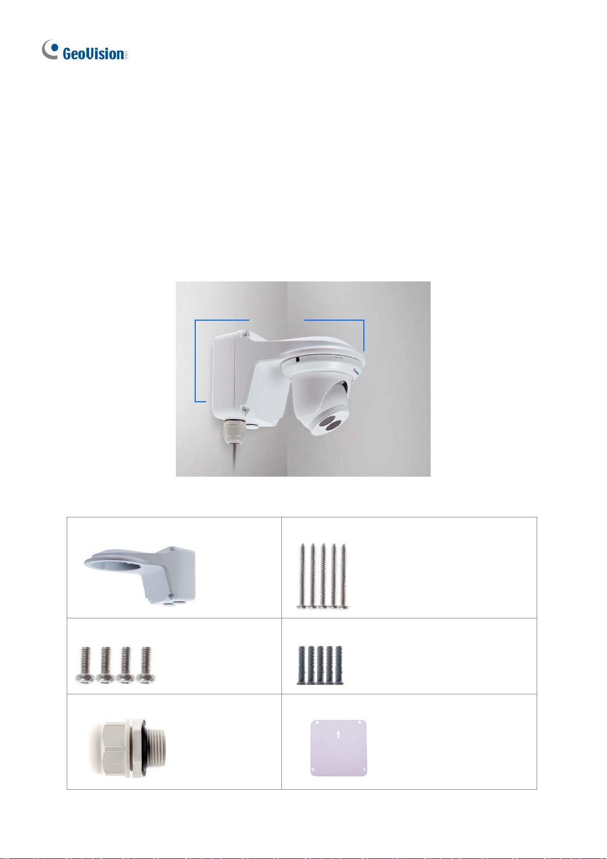
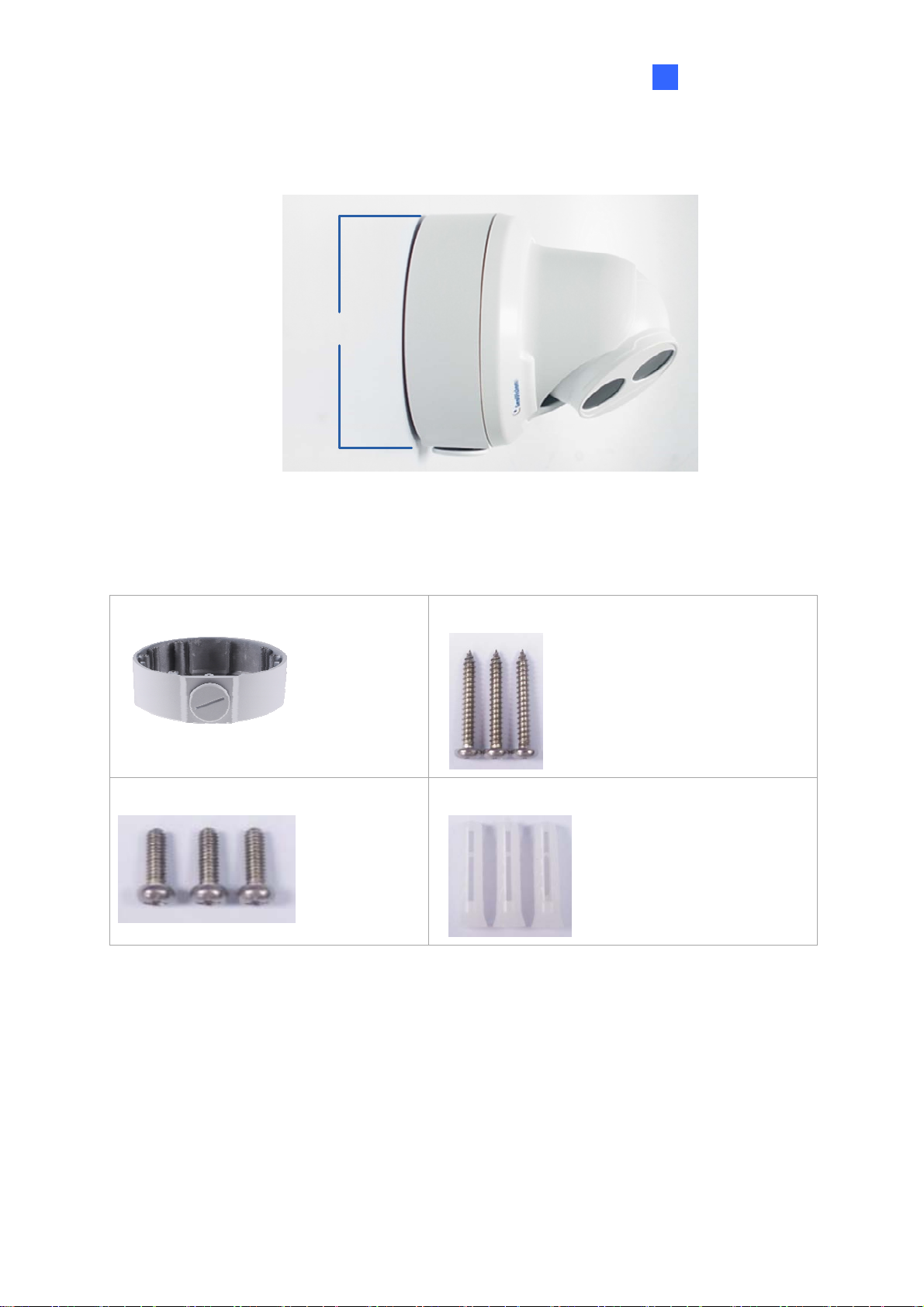
1.1.5.1 GV-Mount211P
GV-Mount211P
GV-Mount211
GV-Mount211P Packing List
GV-Mount211P
Short Screw x 4
Plastic PG21 Conduit Connector
Figure 1-17
Long Screw x 5
Screw Anchor x 5
Drill Template Paster
12
Page 24
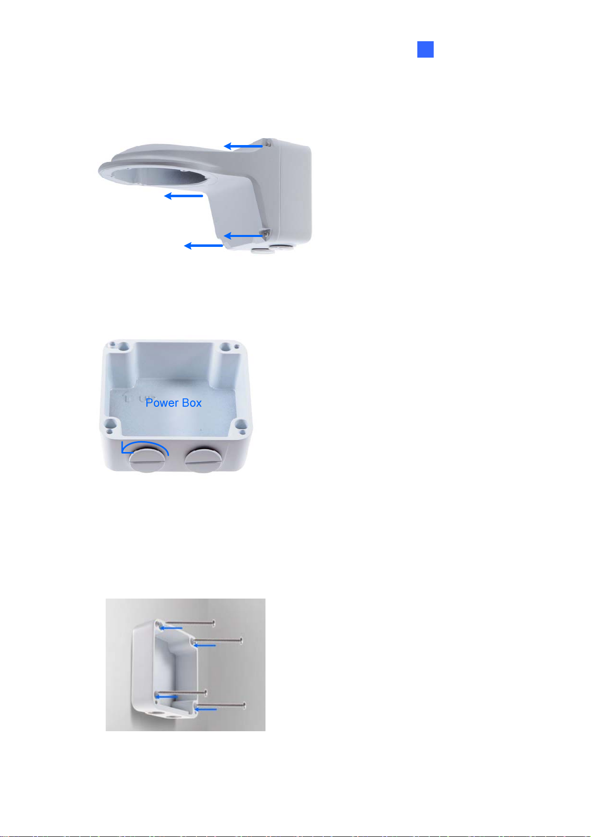
1.
Unscrew the bracket.
Figure 1-18
2. Loosen the indicated area by turning it anticlockwise.
Introduction
1
Figure 1-19
3. Stick the drill template paster to the wall with the arrow pointing up.
4. Drill 4 holes according to the sticker and insert the 4 screw anchors to the 4 holes.
5. Secure the power box to the wall with 4 long screws
Figure 1-20
13
Page 25
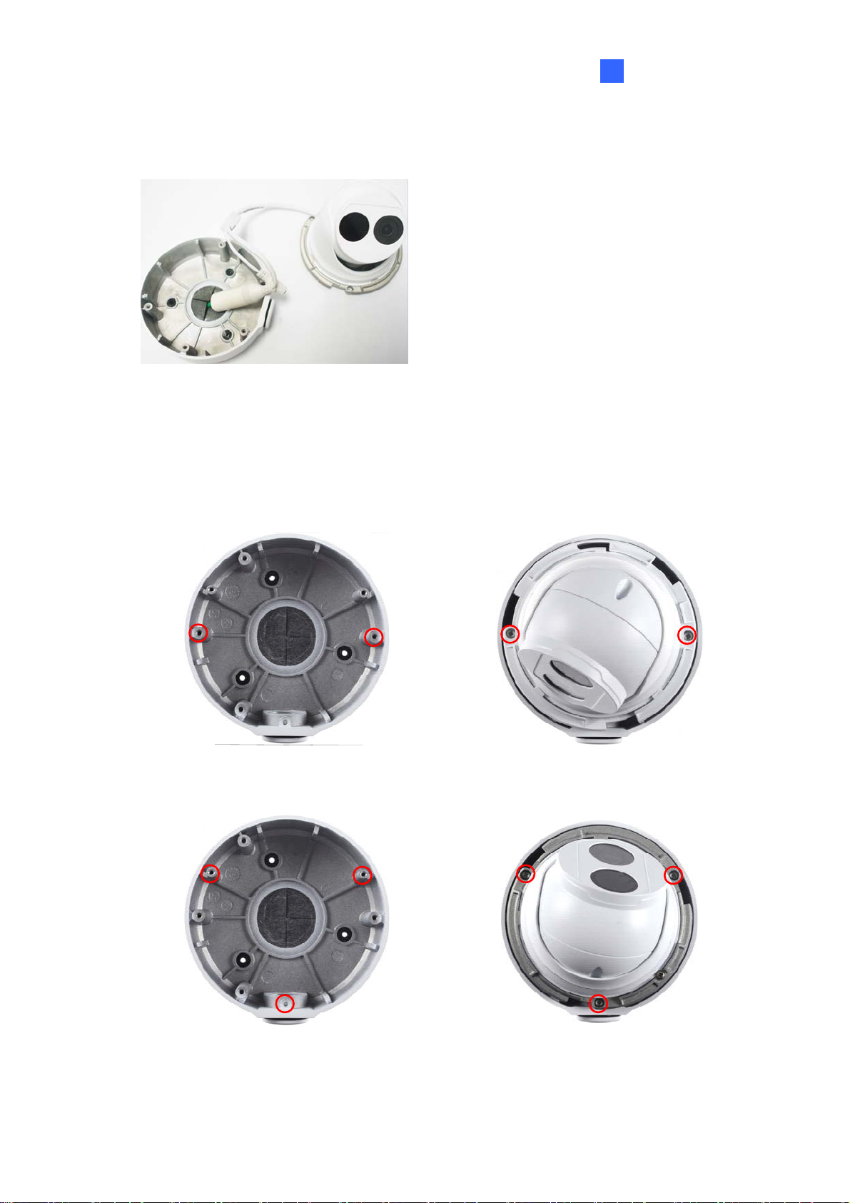
6.
Remove the bottom ring by turning it anticlockwise.
Figure 1-21
7. Secure the camera to the wall mount bracket with the provided short screws
according to the screw position for each model:
GV-EBD4700 / 4711 / 8700 / 8711
Figure 1-22
14
Page 26
GV-EBD2702
GV-ADR2701 / 4701
Figure 1-23
Introduction
1
Figure 1-24
GV-ADR2702 / ADR4702 / TDR2700 / TDR2702 / TDR4700 / TDR4702
Figure 1-25
15
Page 27
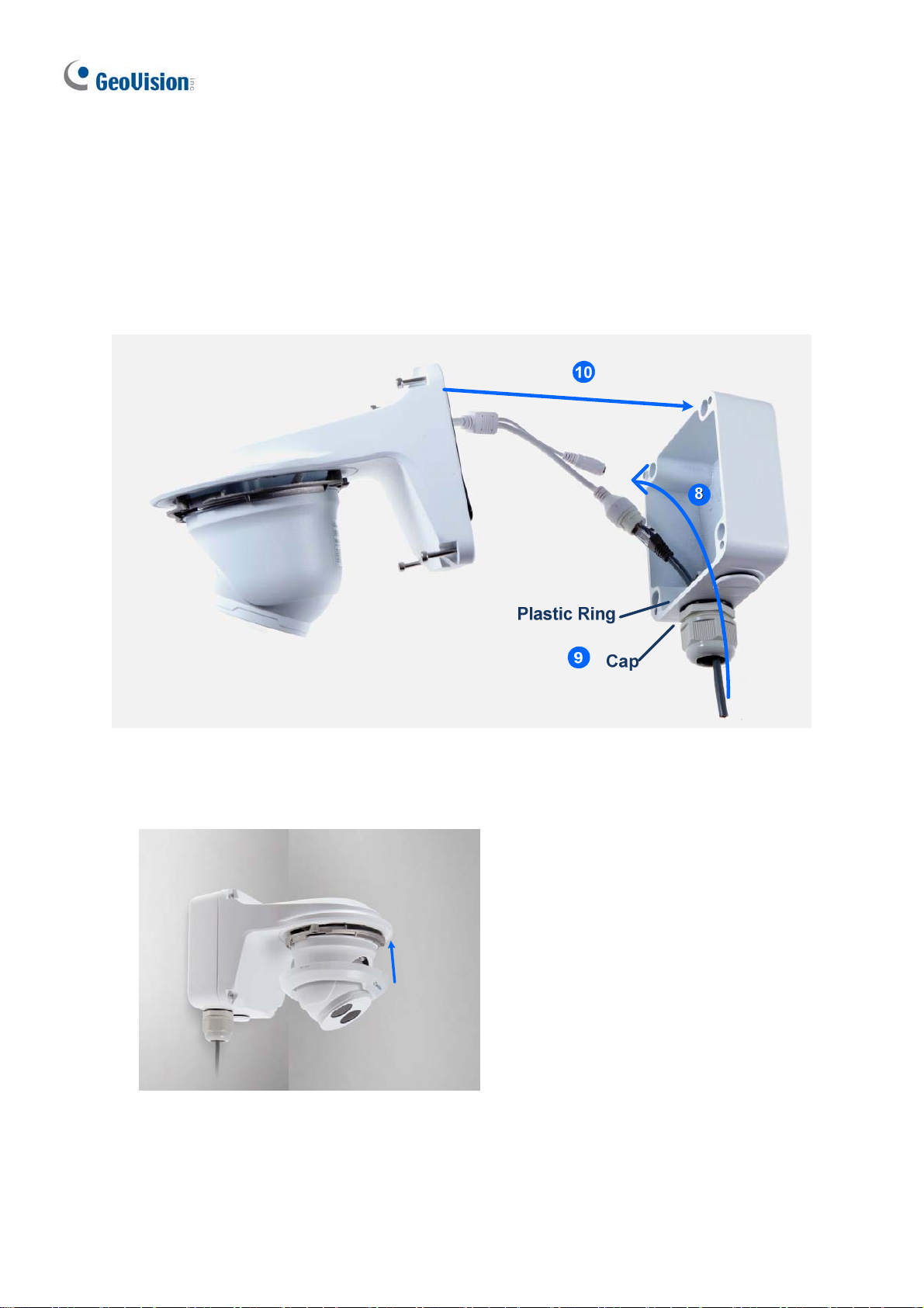
8.
Thread the Ethernet cable through the PG21 conduit connector and the power box as
shown in No. 8, Figure 1-26. Then connect the cable to the camera. To waterproof the
cable, see 1.6 Waterproofing the Cable.
9. Rotate the plastic ring to secure the conduit connector to the power box. Screw in the
cap as shown in No. 9, Figure 1-26.
10. Screw the wall mount bracket to the power box as shown in No. 10, Figure 1-26.
11. Mount the bottom ring.
Figure 1-27
Figure 1-26
16
Page 28
1.1.5.2 GV-Mount212P
GV-Mount212P
Figure 1-28
Introduction
1
GV-Mount212P Packing List
GV-Mount212P
Short Screw x 3
Long Screw x 3
Screw Anchor x 3
17
Page 29
St
andard Installation
1 Attach the wall box to the wall and use a marker to mark the location for the center
socket and the screws. Make sure the knob points down.
Long Screw
This knob points down
Figure 1-29
2 Drill 3 holes according to the screw location. Then, drill a bigger hole at the center
socket location for the Ethernet cable.
3 Insert 3 screw anchors to the screw location and secure the wall box to t he wall with 3
long screws.
4. Remove the bottom ring by turning it anticlockwise.
Figure 1-30
18
Page 30
Introduction
1
5.
Thread the Ethernet cable through the center socket and waterproof the Ethernet cable.
For details, see 1. 6 W aterproofi ng the Cable.
`
Figure 1-31
6. Fit the cable into the wall box.
7. Secure the camera by locking the provided short screws to the screw position for each
model:
GV-EBD2702
Figure 1-32
GV-EBD4700 / 4711 / 8700 / 8711
8. Mount the bottom ring.
Figure 1-33
19
Page 31

ote: In addition to the Standard Installation, you can also choose to run t he Ethernet
N
cable through a corrugated tube. To do this, you will have to purchase your own conduit
connector and corrugated tube. 3/4” NPS is the recommended type of connector. After you
secure the wall box to the desired location, remove the knob at the bottom and connect t he
conduit connector with a self-prepared corrugated tube to the wall box. Then, thread the
Ethernet cable through the corrugated tube and waterproof the Ethernet cable.
Figure 1-34
20
Page 32

1.1.5.3 GV-Mount420 + GV-Mount211P
Figure 1-35
GV-Mount420 Packing List
Introduction
1
GV-Mount420
Additional Screw Kit
- M6 Screw x 4
- M6 Nut x 4
- M6 Plain Washer x 4
- M6 Split Washer x 4
Note: For GV-ADR / TDR / EBD Series, GV-Mount420 can only be used in conjunction
with GV-Mount211P.
M4 Scr ew x 4
21
Page 33

1.
Unscrew the bracket.
Figure 1-36
2. Loosen the indicated area by turning it anticlockwise.
Figure 1-37
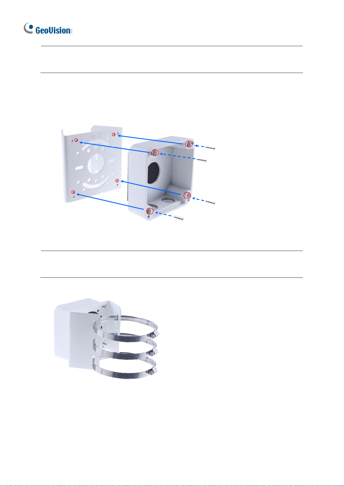
3. Align and attach the power box to the back plate using the 4 supplied M4 screws as
indicated.
Figure 1-38
Note: Make sure the direction of the “up ↑” indicat or on the back plate match that of the
power box.
22
Page 34

1
4.
Thread the 3 steel straps onto the back plate.
Figure 1-39
5. Follow Step 6 ~ 12 in 1.1.5.1 GV-Mount211P.
6. Secure the camera onto the desired pole by tightening the steel straps.
Introduction
23
Page 35

1.1.5.4 GV-Mount212P + GV-Mount107
GV-Mount107
GV-Mount212P
Figure 1-40
GV-Mount107 Packing List
Pendant Bracket
Tube Connector
Pendant Tube
Torx Wrench
Note: Before installing GV-Mount107, note the following.
Install your GV-EBD Series camera on a GV-Mount212P by cutting a hole in the
center of the mount and thread the camera wires through.
Prepare 3 long screws for securing the Pendant Bracket to the ceiling.
GV-Mount107 optionally extends with GV-Mount704.
24
Page 36

Introduction
1
1.
Place GV-Mount107 on the ceiling and mark the location for the center socket and the 3
screws.
2. Drill the marks and secure the Pendant Bracket onto the ceiling.
Figur e 1-41
3. Attach one end of the Pendant Tube to the Pendant Bracket, and the other end to the
Tube Connector.
4. Thread the necessary wires from the ceiling through the Pendant Tube and connect to
the camera wires.
Figure 1-42
5. Push and arrange the connected wires inside Mount212P.
6. Secure the camera onto the Tube Connector.
25
Page 37

1.2 GV-ABL / TBL Series
The Bullet IP Camera is an outdoor, fixed, network camera equipped with an automatic IRcut filter and an IR LED for day and night surveillance. The camera supports H.265 video
codec to achieve better compression ratio while maintaining high quality image at reduced
network bandwidths. The camera adheres to IP66 standards (IP67 for GV-ABL4712 / 8712 /
TBL Series) and can be powered through PoE.
Model No. Specifications Description
GV-ABL2701-0F
Fixed lens
GV-ABL2701-1F
GV-ABL2702 Varifocal Lens
Fixed Iris, f: 4.0 mm, F/1.8,
M12 Lens Mount
Fixed Iris: f: 6.0 mm,
F/1.8, M12 Lens Mount
Fixed Iris, f: 2.8~12 mm, F/1.4,
Ø14 mm Lens Mount
2 MP, H.265,
Low Lux, WDR
2 MP, H.265,
Low Lux, WDR Pro
GV-ABL2703-0F
GV-ABL2703-1F
GV-ABL4701-0F
GV-ABL4701-1F
GV-ABL4703
GV-ABL4712
GV-ABL8712
GV-TBL2703-0F
GV-TBL2703-1F
GV-TBL4700 Varifocal lens
GV-TBL4703 Fixed lens
Fixed lens
Motorized
varifocal lens
Fixed lens
Fixed Iris, f: 4.0 mm, F/2.0,
M12 Lens Mount
Fixed Iris: f: 6.0 mm,
F/2.0, M12 Lens Mount
Fixed Iris, f: 4.0 mm, F/1.8,
M12 Lens Mount
Fixed Iris, f: 6.0 mm, F/1.8,
M12 Lens Mount
Fixed Iris, f: 4.0 mm, F/2.0,
M12 Lens Mount
Fixed Iris, f: 2.8~12 mm, F/1.4,
Ø14 mm Lens Mount
Fixed Iris, f: 4.0 mm, F/2.0,
M12 Lens Mount
Fixed Iris, f: 6.0 mm, F/2.0,
M12 Lens Mount
Fixed Iris, f: 2.8~12 mm, F/1.6,
Ø14 mm Lens Mount
Fixed Iris, f:4 .0 mm, F/2.0,
M12 Lens Mount
2 MP, H.265,
Low Lux, WDR
4 MP, H.265
Low Lux, WDR
4 MP, H.265
Low Lux, WDR Pro
8 MP, H.265
Super Low Lux,
WDR Pro
2 MP, H.265 Low
Lux, WDR
2 MP, H.265 Low
Lux, WDR
4 MP, H.265
Low Lux, WDR
4 MP, H.265 Low
Lux, WDR
GV-TBL4710
GV-TBL4711
GV-TBL8710
Motorized
varifocal lens
Fixed Iris, f: 2.8 ~ 12 mm,
F/1.4, Ø14 mm Lens Mount
Fixed Iris, f: 2.8 ~ 12 mm,
F/1.6, Ø14 mm Lens Mount
Fixed Iris, f: 2.8 ~ 12 mm,
F/1.5, Ø14 mm Lens Mount
26
4 MP, H.265, Low
Lux, WDR Pro
4 MP, H.265, Low
Lux, WDR Pro
8 MP, H.265,
Super Low Lux,
WDR Pro
Page 38
1.2.1 Packing List
Bullet IP Camera Drill Template Paster
Introduction
1
Screw Kit
Download Guide
Warranty Card
Waterproof Rubber Set
1.2.2 Optional Accessories
Optional accessories can expand the capabilities and versatility of your camera. Contact your
dealer for more information.
Model Number Name Details
GV-Mount502 (for GV-
ABL2701 Series / 2703
Series / 4701 Series /
4703 & TBL2703 Series
/ 4703)
Wall Mount Bracket
Dimensions: 93 x 93 x 39 mm
(3.66” x 3.66” x 1.53”)
Weight: 0.235 kg (0.52 lb)
GV-Mount503 (for GV-
ABL2702 / 4712 / 8712,
GV-TBL4700 / 4710 /
4711 / 8710)
GV-Mount300-2 Convex Corner Mount
GV-Mount310-2 Concave Corner Mount
GV-Mount420 (must be
used with GV-Mount503)
Wall Mount Bracket
Pole Mount Bracket
Dimension: 125 x 125 x 55
mm (4.9” x4.9” x2.2”)
Weight: 0.74 kg (1.63lb)
Dimensions: 137 x 233 x 160
mm (5.4” x 9.17” x 6.3”)
Weight: 1.65 kg (3.64 lb)
Dimensions: 111.2 x 369.9 x
210 mm (2.6” x 11.4” x 6.6”)
Weight: 1.65 kg (3.64 lb)
Dimensions: Ø 120 x 120 x
53.4 mm (Ø 4.7” x 4.7” x 2.1”)
Weight: 0.45 kg (0.99 lb)
Steel Strap Diameter: Ø 67 ~
127 mm (Ø 2.6” ~ 5”)
27
Page 39

G
V-PA191
GV-POE Switch
Power Adapter
Power over Ethernet (PoE)
Adapter
GV-POE Switch is designed to provide power along with
network connection for IP devices. GV-POE Switch is
available in various models with different numbers and types
of ports.
Contact our sales representatives for the countries and areas
supported.
GV-PA191 is a Power over
Ethernet (PoE) adapter
designed to provide power to
the IP device through a single
Ethernet cable.
28
Page 40

Introduction
1
1.2.3 Overview
1.2.3.1 GV-ABL2701 / 2703 / 4701 / 4703 & TBL2703 / 4703
Figure 1-43
No. Description No. Description
1 Power connector (DC 12 V) 2 Ethernet connector / PoE
Load Default Button (for GV-ABL2703 / 4703 & TBL2703 / 4703 only)
Figure 1-44
No. Description No. Description
1 Load default button 2 Grounding screw
Note:
1. For safety precautions, it is recommended to connect a grounding wire to the
grounding screw, and do not loosen or remove the grounding screw under any
circumstances.
2. If the default button doesn’t respond after pressing for 15 seconds, reboot the camera
and try again within 10 minutes of rebooting.
29
Page 41

1.2.3.2 GV-ABL2702 / 4712 / 8712 & TBL4700 / 4710 / 4711 / 8710
1
2
3
4
5
Figure 1-45
No. Description
1 Power connector (DC 12 V)
2 Audio input / Audio output / GND
3 Alarm input (IN, GND) / Alarm output (N,P)
4 Ethernet connector / PoE
5 Video Output (GV-ABL8712 / TBL8710 Only)
30
Page 42

Introduction
1
1.2.4 Installation
The Bullet IP Camera is designed for outdoors. With the standard package, you can install
the camera on the wall or ceiling. Or, you can purchase optional mounting accessories to
mount your camera on a wall.
Below are the instructions for Wall Mount. There are two kinds of Wall Mount: Concealed
Installation and Open Installation. In Concealed Installation, the cables are hidden in the
wall. In Open Installation, the cables are led out from the open slot on the base.
For Concealed Installation
1. For GV-ABL2702 / 4712 / 8712 & TBL4700 / 4710 / 4711 / 8710, optionally loosen the
two screws at the bottom of the camera to insert a SD card.
Figure 1-46
2. Stick the drill template paster to the wall and align the cross center to the hole in the wall.
3. Lead the cables across the hole on the wall.
Figure 1-47
31
Page 43

4.
Drill four 30-mm deep holes according to the drill template.
Figure 1-48
5. Insert the screw anchors.
Figure 1-49
6. Screw the locknut and loosen the universal joint before attaching the camera to the wall.
Figure 1-50
32
Page 44

7.
Secure the camera to the wall and connect all cables.
Leadtappingscrewsthrough
theguideholesinthebase
andfixthemonthewallby
usingascrewdriver.
Introduction
1
Figure 1-51
8. Adjust the monitoring direction.
Figure 1-52
For Open Installation
Lead the cables out from the open slot on the base before screwing the camera to t he wall
as shown in Figure 1-51.
33
Page 45
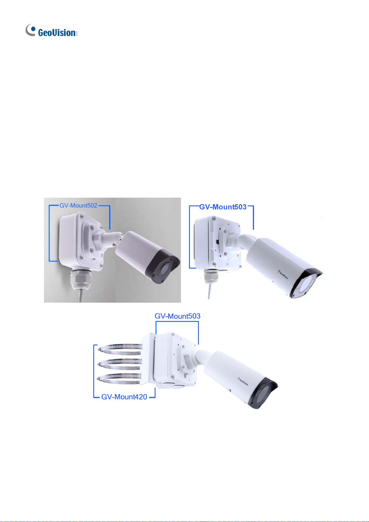
1.2.5 Optional Installation
For GV-ABL2701 Series / 2703 Series / 4701 Series / 4703 & TBL2703 Series / 4703, you
can optionally purchase the following accessories to fit your mounting environment:
GV-Mount502 for Wall Box Mount: see section 1.2.5.1.
For GV-ABL2702 / 4712 / 8712 / TBL Series, you can optionally purchase:
GV-Mount503 for Wall Box Mount: see section 1.2.5.2.
GV-Mount420 + GV-Mount503 for Pole Box Mount: see section 1.2.5.3.
GV-Mount300-2 / 310-2 for Corner Mount: see Appendix F. GV-Mount300-2 / 310-2.
Figure 1-53 Figure 1-54
Figure 1-55
34
Page 46

1.2.5.1 GV-Mount502
GV-Mount502 Packing List
Introduction
1
GV-Mount502
M3 12 mm Screw x 4
Plastic PG21 Conduit Connector
M3 25 mm Screw x 4
Screw Anchor x 4
1. Unscrew the box cover.
Figure 1-56
35
Page 47

2. Loosen the knob by turning it anticlockwise.
Figure 1-57
3. Attach the box to the wall with the knob pointing down and use a m arker to mark 4 dots.
4. Drill 4 holes according to the marks.
5. Insert the 4 screw anchors to the holes and secure the box to the wall with 4 long screws.
6. Secure the camera to the box cover with 4 short screws, as illustrated in No. 6, Figure 1-
58.
7. Thread the Ethernet cable through the PG21 conduit connector and the wall box, as
shown in No. 7, Figure 1-58. Then connect the cable to the camera. To waterproof the
Ethernet cable, see 1.6 Waterproofing the Cable.
8. Rotate the plastic ring to secure the conduit connector to the wall box. Scr ew in the cap,
as shown in No. 8, Figure 1-58.
9. Screw the box cover to the wall box, as shown in No. 9, Figure 1-58.
Figure 1-58
36
Page 48

1.2.5.2 GV-Mount503
GV-Mount503 Packing List
Introduction
1
GV-Mount503
Short Screw x 4
Plastic PG21 Conduit Connector
Long Screw x 4
Screw Anchor x 4
Waterproof Rubber Plug
1. 1. Unscrew the box cover.
Figure 1-59
37
Page 49

2.
Loosen the knobs by turning it anticlockwise.
Figure 1-60
3. Attach the box to the wall with the knobs pointing down and use a m arker to mark 4 dots.
4. Drill 4 holes according to the marks.
5. Insert 4 screw anchors to the holes and secure the to the wall with 4 long screws.
6. Thread the camera cable through the box cover and secure the camer a to the cover with
4 short screws.
7. Reattach the box cover to the power box, as shown in No. 7, Figure 1-61.
8. Thread the Ethernet cable through the PG21 conduit connector and the power box as
shown in No 8, Figure 1-61. Then connect the cable to the camera. To waterproof the
cable, see 1.6 Waterproofing the Cable.
9. Rotate the plastic ring to secure the conduit connector to the power box. Secure in the
cap, as shown in No 9, Figure 1-61
10. Secure the box cover to the power box, as shown in No 10, Figure 1-61.
Figure 1-61
38
Page 50

Introduction
1
e: Alternatively, you can use the supplied waterproof rubber plug to seal the box cover
Not
by following the steps below.
1. Thread the camera cable through the box cover, and then through the supplied
waterproof rubber plug from the bottom side.
Figure 1-62
2. Align the gap of the waterproof rubber plug to the direction of the “up ↑” indicator and
press firmly to embed the waterproof plug onto the inside of the box cover.
3. Thread the Ethernet cable through the power box and connect to the camer a. Secur e
the box cover to the power box.
1.2.5.3 GV-Mount420 + GV-Mount503
GV-Mount420 Packing List
GV-Mount420
Additional Screw Kit
M4 Scr ew x 4
- M6 Screw x 4
- M6 Nut x 4
- M6 Plain Washer x 4
- M6 Split Washer x 4
39
Page 51
ote: For GV-ABL2702 / 4712 / 8712 and TBL Series, GV-Mount420 can only be used in
N
conjunction with GV-Mount503.
1. Follow Step 1 & 2 in 1.2.5.2 GV-Mount503.
2. Align and attach the power box to the back plate using the 4 supplied M4 screws as
indicated.
Figure 1-63
Note: Make sure the direction of the “up ↑” indicat or on the back plate matches that of the
power box.
3. Thread the 3 steel straps onto the back plate.
Figure 1-64
4. Follow Step 6 ~ 10 in 1.2.5.2 GV-Mount503.
Secure the camera onto the desired pole by tightening the steel straps.
40
Page 52

Introduction
1
1.3 GV-ADR / TDR Series
The IR Mini Fixed Rugged IP Dome is an outdoor, fixed, network camera equipped with an
automatic IR-cut filter and an IR LED for day and night surveillance. The camera supports
H.265 video codec to achieve better compression ratio while maintaining high quality image
at reduced network bandwidths. The WDR Pro models can produce clear image for scenes
containing contrasting intensity of lights.
Model No. Specifications Description
GV-ADR2701
GV-ADR2702-0F
GV-ADR2702-1F
GV-ADR4701
GV-ADR4702-0F
Fixed lens
Fixed Iris, f: 2.8 mm,
F/2.2, M12 Lens Mount
Fixed Iris, f: 2.8 mm,
F/2.0, M12 Lens Mount
Fixed Iris, f: 4 mm,
F/2.0, M12 Lens Mount
Fixed Iris, f: 2.8 mm,
F/1.8, M12 Lens Mount
Fixed Iris, f: 2.8 mm,
F/2.0, M12 Lens Mount
2 MP, H.265,
Low Lux, WDR
2 MP, H.265, Low
Lux, WDR
4 MP, H.265,
Low Lux, WDR
4 MP, H.265, Low
Lux, WDR
GV-ADR4702-1F
GV-TDR2700-0F
GV-TDR2700-1F
GV-TDR2702-0F
Fixed Iris, f: 4 mm,
F/2.0, M12 Lens Mount
Fixed Iris, f: 2.8 mm,
F/1.6, M12 Lens Mount
Fixed Iris, f: 4 mm,
F/1.6, M12 Lens Mount
Fixed Iris, f: 2.8 mm,
F/2.0, M12 Lens Mount
41
2 MP, H.265, Low
Lux, WDR Pro
2 MP, H.265, Low
Lux, WDR
Page 53
GV-TDR2702-1F
GV-TDR4700-0F
GV-TDR4700-1F
GV-TDR4702-0F
GV-TDR4702-1F
Fixed lens
Fixed Iris, f: 4 mm,
F/2.0, M12 Lens Mount
Fixed Iris, f: 2.8 mm,
F/2.0, M12 Lens Mount
Fixed Iris, f: 3.6 mm,
F/2.0, M12 Lens Mount
Fixed Iris, f: 2.8 mm,
F/2.0, M12 Lens Mount
Fixed Iris, f: 4 mm,
F/2.0, M12 Lens Mount
2 MP, H.265, Low
Lux, WDR
4 MP, H.265, Low
Lux, WDR Pro
4 MP, H.265, Low
Lux, WDR
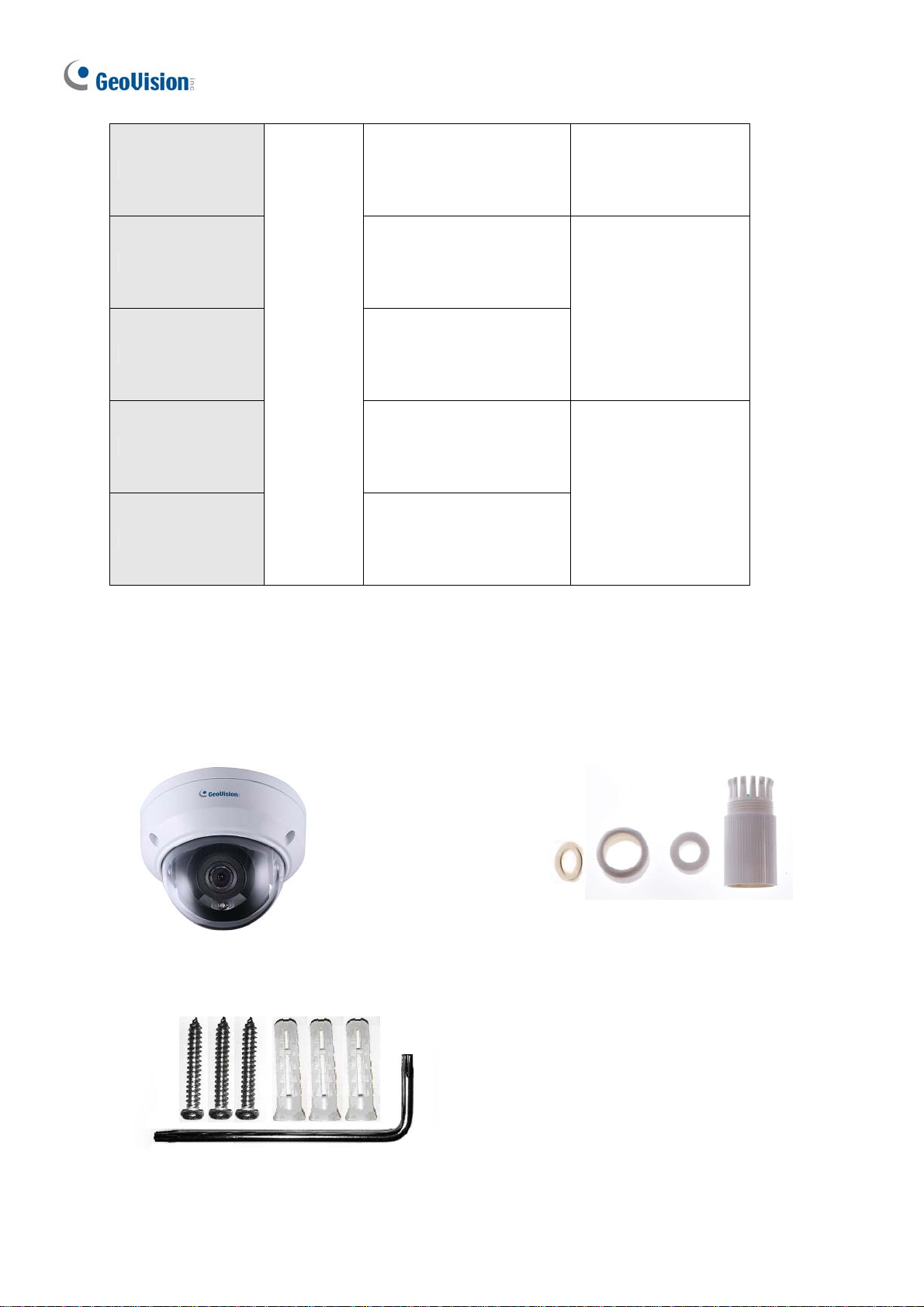
1.3.1 Packing List
IR Mini Fixed Rugged IP Dome
Screw Kit
Waterproof Rubber Set
Drill Template Paster
Download Guide
Warranty Card
42
Page 54

Introduction
1
1.3.2 Optional Accessories
Optional accessories can expand the capabilities and versatility of your camera. Contact your
dealer for more information.
Model Number Name Details
GV-Mount107
Pendant Bracket
(must be used with
GV-Mount213)
GV-Mount211P Wall Mount and Junction Box
GV-Mount213 Wall / Ceiling Box Mount
GV-Mount300-2
Convex Corner Mount
(must be used with
GV-Mount211P or
GV-Mount213 for
GV-ADR2701 /
4701)
Dimensions: Ø 120 x 334 mm (Ø
4.72” x 13.15”)
Weight: 0.74 kg (1.63 lb)
Dimensions: 233 x 126 x 126 mm
(9.2” x 5” x 5”)
Weight: 1 kg (2.2 lb)
Dimensions: Ø 109 x 39 mm
(Ø 4.3” x 1.5”)
Weight: 0.2 kg (0.44 lb)
Dimensions: 137 x 233 x 160 mm
(5.4” x 9.17” x 6.3”)
Weight: 1.65 kg (3.64 lb)
GV-Mount310-2
(must be used with
GV-Mount211P or
GV-Mount213 for
GV-ADR2701 /
4701)
GV-Mount420
(must be used with
GV-Mount211P)
GV-Mount704
(must be used with
GV-Mount107)
Concave Corner Mount
Pole Mount Bracket
Extension Tube
43
Dimensions: 111.2 x 369.9 x 210
mm (2.6” x 11.4” x 6.6”)
Weight: 1.65 kg (3.64 lb)
Dimensions: Ø 120 x 120 x 53.4 mm
(Ø 4.7” x 4.7” x 2.1”)
Weight: 0.45 kg (0.99 lb)
Steel Strap Diameter: Ø 67 ~ 127
mm (Ø 2.6” ~ 5”)
Dimensions: Ø 3.5 x 10 or 20 or 30
or 50 cm (Ø 1.38 x 3.9 or 7.9 or 11.8
or 19.7”)
Weight: 225g or 360g or 500g or
780g (0.5 lb or 0.79 lb or 1.1 lb or
1.72 lb)
Page 55

G
V-PA191
GV-POE Switch
Power Adapter Cont act our sales representatives for the countries and areas supported.
Power over Ethernet (PoE)
Adapter
GV-POE Switch is designed to provide power along with network
connection for IP devices. GV-POE Switch is available in various models
with different numbers and types of ports.
GV-PA191 is a Power over Ethernet
(PoE) adapter designed to provide
power to the IP device through a
single Ethernet cable.
44
Page 56

1.3.3 Overview
Introduction
1
Wire Definition
Figure 1-65
No. Description
1 Ethernet connector / PoE
2 Power connector (DC 12 V)
3 Tr ansparent Dome Cover
4
For GV-TDR2700 / 4700 only, see the table
below.
Wire Definition
Green Audio in
Blue GND
Yellow Alarm Out
White Alarm Out
Orange Alarm Input
Blue GND
Brown Audio in
Blue GND
Gray Audio Out
Purple GND
45
Page 57

1.3.4 Installation
The IR Mini Fixed Rugged IP Dome is designed for outdoors. With the standard package,
you can install the camera on the ceiling.
Below are the instructions for Ceiling Mount. There are two kinds of Ceiling Mount:
Concealed Installation and Open Installation. In Concealed Installation, the cables are
hidden in the ceiling. In Open Installation, the cables are led out from the open slot on the
camera base.
For Concealed Installation
1. Stick the drill template paster to the ceiling and drill 30-mm deep holes according to the
drill template.
Figure 1-66
2. Insert the screw anchors.
Figure 1-67
46
Page 58

3.
Unscrew the transparent dome cover with the supplied torx wrench.
4. Connect the cables and secure the camera.
Introduction
1
Figure 1-68
5. Adjust the monitoring direction and tighten the screws after vertically adjusting the lens.
Figure 1-69
47
Page 59

6.
Secure the transparent dome cover with the supplied torx wrench.
Figure 1-70
Note: Before securing the transparent dome cover, make sur e the waterproof rubber strip is
tightly held by the six retainers on the bottom ring.
Figure 1-71
For Open Installation
Lead the cables out from the open slot on the cam era base before screwing the camera to
the ceiling as shown in Figure 1-68.
48
Page 60
Introduction
1
1.3.5 Optional Installation
You can optionally purchase the following accessories to fit your mounting environment:
GV-Mount211P for Wall Mount: see section 1.1.5.1.
GV-Mount213 for Wall / Ceiling Box Mount: see section 1.3.5.1
GV-Mount420 + GV-Mount211P for Pole Box Mount: see section 1.1.5.3.
GV-Mount213 + Mount107 for Pendant Bracket Mount: see section 1.1.5.4.
GV-Mount300-2 / 310-2 for Corner Mount: see Appendix F. GV-Mount300-2 / 310-2.
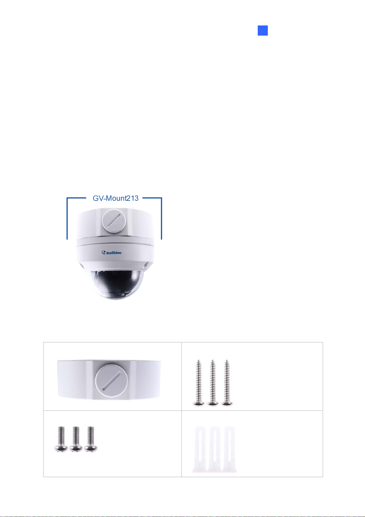
1.3.5.1 GV-Mount213
Figure 1-72
GV-Mount213 Packing List
GV-Mount213
Short Screw x 3
Long Screw x 3
Screw Anchor x 3
49
Page 61

1.
Attach the GV-Mount213 to the wall / ceiling and use a marker to mark the location for
the center socket and the 3 screws.
Figure 1-73
Note: To prevent rain from getting into GV-ADR2701 / 2702 / 4701 / 4702 & T DR2702 /
4702,
For ceiling mount installation, turn the indicated hole inwards.
For wall mount installation, make sure the indicated hole points down and towards the
ground.
Figure 1-74
2. Drill 3 holes according to the screw locations. Then, drill a bigger hole at the center
socket location for the Ethernet cable.
50
Page 62

Introduction
1
3.
Insert 3 screw anchors to the screw locations and secure the GV-Mount 213 t o the wall /
ceiling with 3 long screws.
4. Thread the Ethernet cable through the center socket and waterproof the Ethernet cable.
For details, see 1.6 Waterp roofing the C able.
Figure 1-75
5. Fit the cable into the GV-Mount213.
6. Remove the camera cover and fasten the camera to the wall box mount as indicated
below using the supplied short screws.
GV-ADR2701 / 4701
Figure 1-76
51
Page 63

GV-ADR2702 / ADR4702 / TDR2700 / TDR2702 / TDR4700 / TDR4702
Figure 1-77
7. Secure the camera cover.
Note: In addition to the Standard Installation, you can also choose t o run the Ethernet
cable through a corrugated tube. To do this, see Figure 1-34 and its related Note.
52
Page 64

Introduction
1
1.4 GV-AVD / TVD Series
The Vandal Proof IP Dome is an outdoor camera designed with IK10 vandal resistance and
IP67 ingress protection. The camera is equipped with an automatic IR-cut filter and IR LEDs
for day and night surveillance. Adjustable in 3 axes (pan, tilt and rotate), it offers an entrylevel surveillance solution with all the essential features and excellent image quality.
Model No. Specifications Description
GV-AVD2700 Varifocal lens
GV-AVD4710
Motorized
varifocal lens
GV-AVD8710
GV-TVD4700 Varifocal lens
GV-TVD4710
Fixed Iris, f: 2.8~12 mm,
F/1.4, Ø14 mm Lens
Mount
Fixed Iris, f: 2.8~12 mm,
F/1.5, Ø14 mm Lens
Mount
Fixed Iris, f: 2.8~12 mm,
F1.6, Ø14 mm Lens
Mount
Fixed Iris, f: 2.8~12 mm,
F/1.4, Ø14 mm Lens
Mount
2MP, H.265,
Low Lux, WDR
4 MP, H.265,
Low Lux, WDR Pro
8 MP, H.265,
Super Low Lux,
WDR Pro
4 MP, H.265,
Low Lux,
WDR
4 MP, H.265,
Low Lux, WDR Pro
GV-TVD4711
GV-TVD8710
Motorized
varifocal lens
Fixed Iris, f: 2.8~12 mm,
F/1.6, Ø14 mm Lens
Mount
Fixed Iris, f: 2.8~12 mm,
F/1.5, Ø14 mm Lens
Mount
53
4 MP, H.265,
Low Lux, WDR Pro
8 MP, H.265,
Super Low Lux,
WDR Pro
Page 65

1.4.1 Packing List
1.4.1.1 GV-TVD4711
IR Vandal Proof IP Dome
Drill Template Paster
Spare Waterproof Rubber Plug
Screw Kit
Torx Wrench
Cable Protection Connector
2-Pin Power Terminal Block
Warranty Card
Download Guide
54
Page 66

1
1.4.1.2 GV-AVD / TVD Series
IR Vandal Proof IP Dome Waterproof Rubber Set
Introduction
Screw Kit
Torx Wrench
Drill Template Paster
Warranty Card
Download Guide
55
Page 67

1.4.2 Optional Accessories
Optional accessories can expand the capabilities and versatility of your camera. Contact your
dealer for more information.
Model Number Name Details
GV-Mount107
(must be used with
GV-Mount212-2)
GV-Mount211-2 Wall Mount and Junction Box
GV-Mount212-2 Ceiling Box Mount
GV-Mount300-2 Convex Corner Mount
GV-Mount310-2 Concave Corner Mount
Pendant Bracket
Dimensions: Ø 120 x 334 mm (Ø
4.72” x 13.15”)
Weight: 0.74 kg (1.63 lb)
Dimensions: 253 x 125 x 125 mm
(10” x 4.9” x 4.9”)
Weight: 0.92 kg (2.02 lb)
Dimensions: Ø145 x 40 mm
(Ø 5.7” x 1.6”)
Weight: 0.24 kg (0.5 lb)
Dimensions: 137 x 233 x 160 mm
(5.4” x 9.17” x 6.3”)
Weight: 1.65 kg (3.64 lb)
Dimensions: 111.2 x 369.9 x 210
mm (2.6” x 11.4” x 6.6”)
Weight: 1.65 kg (3.64 lb)
GV-Mount420
(must be used with
GV-Mount211-2)
GV-Mount606 In-Ceiling Mount
Pole Mount Bracket
56
Dimensions: Ø 120 x 120 x 53.4
mm (Ø 4.7” x 4.7” x 2.1”)
Weight: 0.45 kg (0.99 lb)
Steel Strap Diameter: Ø 67 ~ 127
mm (Ø 2.6” ~ 5”)
Dimensions: Ø 235 x 63 mm (Ø
9.3” x 2.5”)
In-ceiling hole: Ø 195 mm (Ø
7.67”)
Weight: 0.49 kg (1.1 lb)
Page 68

G
V-Mount704
(must be used with
GV-Mount107)
Extension Tube
Introduction
1
Dimensions: Ø 3.5 x 10 or 20 or 30
or 50 cm (Ø 1.38 x 3.9 or 7.9 or
11.8 or 19.7”)
Weight: 225g or 360g or 500g or
780g (0.5 lb or 0.79 lb or 1.1 lb or
1.72 lb)
GV-PA191
Power over Ethernet (PoE)
Adapter
GV-PA191 is a Power over
Ethernet (PoE) adapter designed
to provide power to the IP device
through a single Ethernet cable.
GV-POE Switch
GV-POE Swit ch is designed to provide power along with network
connection for IP devices. GV-POE Switch is available in various
models with different numbers and types of ports.
Power Adapter
Contact our sales representatives for the countries and areas
supported.
1.4.3 Overview
1.4.3.1 GV-AVD2700 / 4710 / 8710, GV-TVD4700 / 4710 / 8710
Figure 1-78
No. Description No. Description
1 Power connector (DC 12 V) 5 Alarm input (IN,GND) / Alarm output (N,P)
2 Ethernet connector / PoE 6 Default button
3 Video output 7 Micro SD card slot
4 Audio input / Audio output / GND
Note: If the default button doesn’t respond after pressing for 15 seconds, reboot the
camera and try again within 10 minutes of rebooting.
57
6
7
Page 69

1.4.3.2 GV-TVD4711
Figure 1-79
No. Description No. Description
1 Ethernet port 7 GND
2 Power port (2-Pin terminal block) 8 Digital Input
3 Micro SD card slot 9 GND
4 Default button 10 Audio In
5 Digital Output (N) 11 GND
6 Digital Output (P) 12 Audio Out
Note: There are two ways to supply power t o the camera:
Use a Power over Ethernet (PoE) adapter to connect the camera to the network, and
the power will be provided at the same time.
Plug the power adapter to the supplied 2-pin terminal block by inserting the striped
wire to the right pin (-) and the black wire to the left pin (+), then insert the 2-pin
terminal block to Power Connector, No. 2.
Figure 1-80
58
Page 70

Introduction
1
1.4.4 Installation
The Target Vandal Proof Dome is designed for outdoors. With the standard package, you
can install the camera on the ceiling. Alternatively, you can purchase optional mounting
accessories to mount the camera on a wall.
Below are the instructions for Ceiling Mount. There are two kinds of Ceiling Mount:
Concealed Installation and Open Installation. In Concealed Installation, the cables are
hidden in the ceiling. In Open Installation, the cables are led out from the open slot on the
camera base.
1.4.4.1 GV-AVD2700 / 4710 / 8710, GV-TVD4700 / 4710 / 8710
For Concealed Installation
1. Stick the drill template paster to the ceiling, and then drill three holes according to the drill
template.
Figure 1-81
2. Insert the screw anchors.
Figure 1-82
3. Unscrew the transparent dome cover with the supplied torx wrench.
59
Page 71

4.
Connect the camera cables and secure the camera.
Figure 1-83
5. Insert a SD card into the
6. Adjust the monitoring direction
Figure 1-84
7. Secure the transparent dom
slot.
e cover with the supplied torx wrench.
and tighten the screws after vertically adjusting the lens.
pen Installation
For O
Lead the cables out from
the ceiling as shown in Figure 1-83.
the open slot on the camera base before screwi ng the camera to
60
Page 72

Introduction
1
1.4.4.2 GV-TVD4711
1. Follow steps 1 to 3 in 1.4.4.1 GV-AVD2700 / 4710 / 8710, GV-TVD4700 / 4710 / 8710.
To install an Ethernet / PoE cable:
2. Remove the large waterproof rubber plug from the base of the camera.
3. Cut a small opening on the tip of the large waterproof rubber plug.
4. Attach the cable protection connector to the Ethernet cable head and push the Ethernet
cable through the opening.
5. Remove the cable protection connector. Thread the Ethernet cable through the large
hole to connect to the camera and press to embed the waterproof rubber plug.
Figure 1-85
To install optional power and I/O wires:
6. Repeat steps 2 to 3 for the small waterproof rubber plug at the base of the camera.
7. Push the power and I/O wires through the opening on the small waterproof plug.
8. Thread the wires through the small hole and press to embed the wat erproof rubber plug.
9. Attach the supplied 2-pin terminal block to the power wires.
61
Page 73

10.
Connect the 2-pin terminal block and I/O wires to the camera.
Tip: When connecting the I/O wir es to the camera, thread the I/O wires through the
protruded loop.
Figure 1-86
To finish the installation:
11. Secure the camera and insert a micro SD card to the slot.
12. Secure the transparent dome cover with the supplied torx wrench.
62
Page 74

Introduction
1
1.4.5 Optional Installation
You can optionally purchase the following accessories to fit your mounting environment:
GV-Mount211-2 for Wall Mount: see section 1.4.5.1.
GV-Mount212-2 for Wall / Ceiling Box Mount: see section 1.4.5.2.
GV-Mount420 + GV-Mount211-2 for Pole Box Mount: see section 1.4.5.3.
GV-Mount212-2 + Mount107 for Pendant Bracket Mount: see section 1.1.5.4.
GV-Mount606 for In-Ceiling Bracket Mount: see section 1.4.5.4.
GV-Mount300-2 / 310-2 for Corner Mount: see Appendix F. GV-Mount300-2 / 310-2.
1.4.5.1 GV-Mount211-2
Figure 1-87
GV-Mount211-2 Packing List
GV-Mount211-2
Short Screw x 4
Plastic PG21 Conduit Connector
Long Screw x 5
Screw Anchor x 5
Drill Template Paster
63
Page 75

1.
To install the power box from the wall mount bracket on the wall, follow steps 1 to 5 in
1.1.5.1 GV-Mount211P.
2. Unscrew the transparent dome cover with the supplied torx wrench.
Figure 1-88
3. Optionally insert a SD card into the slot.
4. Thread the camera cables through the bracket.
5. Secure the camera to the wall mount bracket with the provided short screws.
Figure 1-89
64
Page 76
Introduction
1
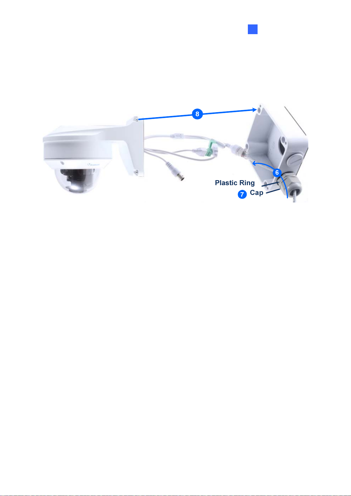
6.
Thread the Ethernet cable through the PG21 conduit connector and the power box, as
shown in No 6, Figure 1-90. Then connect the cable to the camera.
7. Rotate the plastic ring to secure the conduit connector to the power box. Screw in the cap
shown in No 7, Figure 1-90.
8. Screw the wall mount bracket to the power box, as shown in No. 8, Figure 1- 90.
Figure 1-90
65
Page 77

1.4.5.2 GV-Mount212-2
GV-Mount212-2
Figure 1-91
GV-Mount212-2 Packing List
GV-Mount212-2
Short Screw x 3
Long Screw x 3
Screw Anchor x 3
66
Page 78

Introduction
1
1.
Attach the ceiling box to the ceiling and use a marker to mark the location for the center
socket and the screws. Make sure the knob points inwards.
Figure 1-92
2. Drill 3 holes according to the screw location. Then, drill a bigger hole at the center socket
location for the Ethernet cable.
3. Insert 3 screw anchors to the screw location and secure the ceiling box to t he ceiling with
3 long screws.
4. Thread the Ethernet cable through the center socket, connect other wires and fit the
camera cable into the ceiling box. See 1.6 Waterproofing the Cable.
Figure 1-93
5. Unscrew the transparent dome cover with the supplied torx wrench.
67
Page 79

6.
Secure the camera to the ceiling box.
Figure 1-94
Note: In addition to the Standard Installation, you can also choose t o run the Ethernet
cable through a corrugated tube. To do this, see Figure 1-34 and its related Note.
68
Page 80

1.4.5.3 GV-Mount420 + GV-Mount211-2
Figure 1-95
Introduction
1
GV-Mount420 Packing List
GV-Mount420
Additional Screw Kit
- M6 Screw x 4
- M6 Nut x 4
- M6 Plain Washer x 4
- M6 Split Washer x 4
Note: For GV-AVD Series, GV-Mount420 can only be used in conjunction with GVMount211-2.
M4 Scr ew x 4
1. Follow Step 1 ~ 4 in 1.1.5.3 GV-Mount420 + GV-Mount211P.
2. Follow Step 2 ~ 8 in 1.4.5.1 GV-Mount211-2.
3. Secure the camera onto the desired pole by tightening the steel straps.
69
Page 81

1.4.5.4 GV-Mount606
Figure 1-96
GV-Mount606 Packing List
In-Ceiling Mount Bracket
In-Ceiling Plate
Screw Kit :
In-Ceiling Cover
Drill Template Paster
- M4 Screw (8 mm) x 3
- M4 Screw (40 mm) x 2
70
Page 82

Introduction
1
1.
Paste the drill template to the ceiling and drill the ceiling to the size of the drill template.
2. Place the In-Ceiling Plate behind the ceiling with the flat side facing down.
3. Loosen the knob on the side of the camera and thread the camera wires through.
4. Thread the camera wires through the side of the In-Ceiling Mount Bracket and place the
camera in the Mount Bracket.
Figure 1-97
5. Open the transparent dome cover and insert the 3 M4 Screws (8 mm).
6. Align and secure the camera to the Mount Bracket with 3 M4 Screws (8 mm).
Figure 1-98
7. Connect the camera wires to the necessary wires.
8. Secure the housing cover, flip and hold the camera upside down against the ceiling.
9. Align and secure the Mount Bracket to the In-Ceiling Plate with 2 M4 Screws (40 mm).
Figur e 1-99
10. Put on the In-Ceiling Cover to finish installation.
71
Page 83

1.5 System Requirements
CPU Intel Core i5-4670, 3.40 GHz
Memory DDR3 8 GB RAM
On Board Graphics Intel HD Graphics 4600 (Versions of driver from year 2014 or later
required)
Web Browsers Internet Explorer 11.0 or above
Google Chrome
Microsoft Edge
Mozilla Firefox
Safari
Note:
1. Some functions are not available on non-IE browsers, e.g. Local Settings (see 3.1.2
Local Settings) and Photo (see 3.7.3 Backing Up Storage) are not supported by
Google Chrome.
2. Only H.264 codec is supported for live view on non-IE browsers.
72
Page 84

1
1.6 Waterproofing the Cable
Waterproof the Ethernet cable by using the supplied waterproof rubber set.
1. Attach the seal ring to the RJ-45 plug.
Sealring
Figure 1-100
Introduction
2. Insert the waterproof components through the Ethernet cable as shown below.
3
2
Insertinorder
Figure 1-101
3. Insert the cylindrical waterproof ring into waterproof bolt.
Cylindricalwaterproofring
Waterproofbolt
Figure 1-102
73
Page 85

4. Insert the cable into the RJ-45 plug and screw the waterproof bolt in.
Figure 1-103
5. Screw in the waterproof bolt lid.
Bolt lid
Figure 1-104
6. Finish the waterproof installation.
Figure 1-105
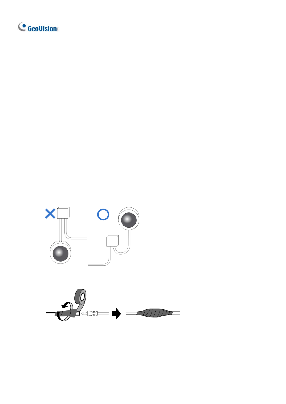
IMPORTANT: Aft er inst alling the camera, it is required to use waterproof tapes to cover
and protect any of the tail cables and connection points that are exposed, see Note for
Installing Camera Outdoor at the beginning of the manual.
74
Page 86

2
Accessing the Camera
Chapter 2 Accessing the Camera
Once installed, the IP camera is accessible on a network. Follow these steps to configure the
network settings and access your surveillance images.
2.1 Installing on a Network
These instructions describe the basic connections to install the camera on the network.
1. Using a standard network cable, connect the camera to your network.
2. Connect to power using one of the following methods:
Use the optional power adapter to connect to power.
Use the Power over Ethernet (PoE) function in which power is supplied over the
network cable.
3. You can now access the Web interface of the camera.
If the camera is installed in a LAN with DHCP server, use GV-IP Device Utility to look
up the camera’s dynamic IP address. See 2.1.1 Looking up the Dynamic IP Address
and Logging In.
If the camera is installed in a LAN without DHCP server, the default IP address
192.168.0.10 is applied. To assign a different static IP address, see 2.1.2 Configuring
the IP Address.
Note: You must set your browser to allow ActiveX Control and perform a one-time
installation of the ActiveX component onto your computer upon your first login.
75
Page 87

2.1.1 Looking Up the Dynamic IP Address and Logging In
By default, when the device is connected to LAN with a DHCP server, it is automatically
assigned with a dynamic IP address. Follow the steps below to look up its IP address and log
in the Web interface.
1. Download and install the GV-IP Device Utility program from the company website.
Note:
1. The PC installed with GV-IP Device Utility must be under the same LAN as the
camera you wish to configure.
2. By default, the Administrator’s username is admin and cannot be modified.
2. On the GV-IP Utility window, click the button to search for the IP devices connected
in the same LAN. Click the Name or Mac Address column to sort.
3. Find the camera with its Mac Address, click on its IP address.
Figure 2-1
4. For the first-time users, you will be requested to set up a password.
5. Type a new password and click OK.
6. Type your username and password on the login page and click Login.
76
Page 88

2
Accessing the Camera
2.1.2 Configuring the IP Address
By default, when the device is connected to LAN without a DHCP server, it is assigned with a
static IP address of 192.168.0.10. Follow the steps below to assign a new IP address to
avoid IP conflict with other GeoVision devices.
1. Open your Web browser and type the default IP address 192.168 .0.10.
2. Type your username and password. Click Login.
3. Click Setup, select Common in the left menu and select Network.
Figure 2-3
4. Select Static IP from the Obtain IP Address drop-down list.
5. Enter the IP address, subnet mask, and default gateway address. Make sure that the IP
address of the camera is unique in the network.
6. Click Save.
Note: When you are changing the network segment through the Web interface or GV-IP
Device Utility, it is required that you change the default gateway, too, for the change to take
effect.
77
Page 89

2.2 Accessing Live View
After logging into the camera, you will see the Home page as shown below:
1 2
3
6
7
8
9
4
5
16
15
17
10
11 12
13
14
Figure 2-4
No. Name Function
Set the display ratio of the image.
Scale: display images by 16:9.
1 Proportional
Stretch: display images by window size.
Original: display images in its original size.
Select a live video stream: main stream, sub stream or third
2 Live Stream
stream (when enabled).
3 Image Open the image setting page. – See 3.4.1 Image.
Only for models with motorized varifocal lens, increase
4 Zoom +/-
decrease
the camera’s optical zoom.
Only for models with motorized varifocal lens, increase
5 Focus +/-
decrease
the camera focus.
15
or
or
78
Page 90

2
Accessing the Camera
6 Play/S
top Play or stop live video.
Only for the audio-support i ng models, adjust the audio output
7 Video Volume
volume on the PC.
Only for audio-supporting models, enable or disable
8
Microphone
microphone.
Only for audio-supporting models, adjust the microphone
Microphone
9
volume on the PC during audio communication between the PC
Volume
and the camera.
10 Snapshot Take a snapshot of the current image displayed on the PC.
11 Local Recor ding Start or stop local recording.
for two-way-audio-supporting models, start or stop
Only
12 Two-way Audio
two-way audio.
Enable
or disable digital zoom. – See 2.2.1 Digital
13 Digital Zoom
Zoom.
14 Full Scr een Display in full screen mode.
Only for models with motorized varifocal lens, hide or show the
15 Control Panel
camera’s optical zoom and focus functions.
16 Reset the packet loss rate to zero.
Click to
always display packet loss rate and bit rate information at
the bottom. Click again to restore to only displaying the
17
information for 3 seconds when the mouse cursor is moved onto
the live view.
Note:
1. The paths for saving snapshots and local recordings are set in Local Settings. See
3.1.2 Local Settings.
2. The No. 16 and 17 buttons will appear on the floating toolbar when you move the
mouse cursor onto the live view.
79
Page 91

2.2.1 Digital Zoom
To use the digital zoom function, follow these steps:
1.
Click
2. Click and drag the mouse button in any direction to specify an area.
3. To restore the original image size, right click on the enlarged area.
4. To exit, click
(No. 13, Figure 2-4) on the toolbar.
(No. 13, Figure 2-4) on the toolbar.
2.2.2 Start Recording
For models with local storage, you can start/stop recording manually or by schedule. At the
top of Home page, select Setup, select Storage in the left menu and select Storage. For
details, see 3.7.1 Formatting Storage.
Figure 2-5
80
Page 92
2
Accessing the Camera
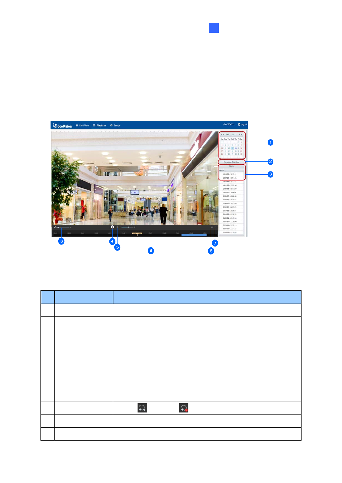
2.3 Playing Back Recorded Videos
Note this function is only applicable to models with SD card slot for local storage.
play back recorded videos from the camera’s local storage, click Playback at the top of
To
the Web interface.
Figure 2-6
No. Name Function
1 Date
Recording
2
Download
3 Query
4 Playback Play back the recorded video select ed.
5 Stop Stop playback of the recorded video selected.
6 Snapshot Take a snapshot of the current playback image displayed.
7 Digital Zoom Enable or disable digital zoom. – See 2.2.1 Digital Zoom.
8 Volume Adjust the audio output volume on the PC.
9 Tim eline Users can select the desired time to play back the video from
Select the date of the video to playback.
Select to download a recorded video from the camera’s local
storage. See 2.4.1 Recording Download for details.
Click Query to show the list of recorded videos of the date
specified.
81
Page 93

Note: To store and play back recorded videos to and from the camera’s local storage, make
sure to conf igure the st or age settings in Storage. For details, refer to 3.7.1 Formatting
Storage.
2.3.1 Recording Download
To download recorded videos from the local storage, follow the steps below:
1. Click
2. Sear ch for video within a specified time period. The results are shown in a list.
3. Select your video and click Download to download a video to your local path from t
4.
Recording Download (No. 2, Figure 2-6) on the right of the Playback window.
Figure 2-7
local storage.
Open to show the folder in which the downloaded videos are sav
Click
ed.
he
82
Page 94

Chapter 3 Administrator Mode
The Administrator can access and configure the GV-IP Camera through the network. Click
Setup at the top of the Web interface to access the following configuration tabs: Common,
Network, Video & Audio, Image, Intelligent, Events, Storage, Security and System.
Figure 3-1
83
Page 95

st of Options
Li
See the table below for the settings available on the Web interface. Find the topic of interest
by referring to the section number prefixed to each option.
IMPORTANT: The available options may vary among camera models and firmware versions.
3.1 Common
3.2 Network
3.3 Video & Audio
3.4 Image
3.1.1 Basic Info
3.1.2 Local Parameters
3.2.1 Network
3.2.2 DNS
3.2.3 Port
3.2.4 DDNS
3.2.5 E-mail
3.2.6 SNMP
3.2.7 802.1x
3.2.8 QoS
3.3.1 Video
3.3.2 Snapshot
3.3.3 Audio
3.3.4 ROI
3.3.5 Media Stream
3.4.1 Image
3.4.2 OSD
3.4.3 Privacy Mask
3.5 Intelligent
3.6 Events
3.7 Storage
3.8 Security
3.9 System
3.5.1 Smart Settings
3.5.2 Advanced Settings
3.6.1 Motion Detection
3.6.2 Tampering Alarm
3.6.3 Audio Detection
3.6.4 Alarm Input
3.6.5 Alarm Output
3.7.1 Formatting Storage
3.7.2 FTP
3.8.1 User
3.8.2 Network Security
3.9.1 Time
3.9.2 Maintenance
84
Page 96

Administrator Mode
3
3.1 Common
Under the Common tab, the Administrator can find the general settings of the camera, as
well as shortcuts to the following setting pages.
Network: See 3.2.1 Networ k for details.
Time: See 3.9.1 Ti me for detai ls.
OSD: See 3.4.2 OSD for details
User: See 3.8.1 User for details
3.1.1 Basic Info
You can view the current status of your camera. Click Refresh for the latest status
information. Under Common Configuration on the right, you can click on the icons to
quickly access the corresponding configuration pages.
Figure 3-2
85
Page 97
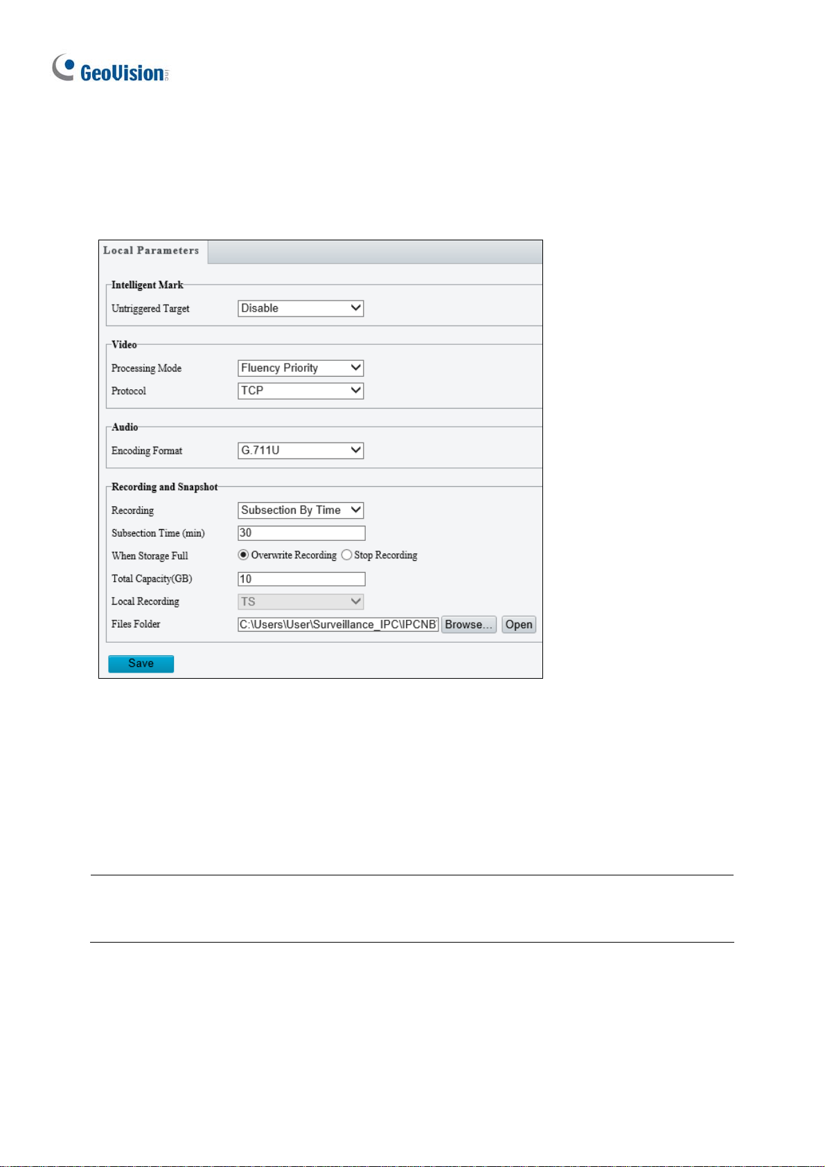
3.1.2 Local Parameters
You can set the local parameters for your PC.
Figure 3-3
[Intelligen t Ma rk]
Untriggered Target: Displays the detection lines / areas defined by Smart Settings on
Live View. You must set up Smart Settings first for this function to work, see 3.5.1 Smart
Settings.
Note: The Intelligent Mark function is not applicable to GV-ABL2701 series / 2703 series /
4701 series / 4703, GV-ADR2701 / 2702 / 4701 / 4702, GV-TBL2703 series / 4700 / 4703 /
4711, TDR2702 / 4702, and GV-TVD4700 / 4711.
86
Page 98

Administrator Mode
3
[V
ideo]
Processing Mode
Real-Time Priority: Select this if the network is in good condition.
Fluency Priority: Select this if you want short time lag for live video.
Ultra-low Latency: Sele ct this if you want the minimum time lag for live video.
Protocol: Select the protocol used to transmit media streams to be decoded by the PC.
[Audio] This function is only applicable to audio-in-supporting models.
Encoding Format: Select the format used to encode audio.
Note: The Video, and Audio functions are not applicable to GV-ABL2701 series / 2703
series / 4701 series / 4703, GV-ADR2701 / 2702 / 4701 / 4702, GV-TBL2703 series / 4700 /
4703, TDR2702 / 4702, and GV-TVD4700.
[Recording and Snapshot]
Recording
Subsection by Time (1~60): Set a maximum time length of each recording file. If
you select 5 minutes, a 30-minute event will be chopped into six 5-minute event files.
Subsection by Size: Set a maximum size limit of each recording file.
When Storage Full
Overwrite Recording: W hen the assigned storage space on the computer is full, the
camera deletes the oldest existing recording files to make room for the new ones.
Stop Recording: When the assigned storage space on the computer is full,
recording stops automatically.
Total Capacity (1~1024): Set a capacity limit to the assigned storage space on the
computer.
Files Folder: Click Browse to set a folder to store the recorded videos and captured
snapshots at your local computer.
87
Page 99

3.2 Network
The network section allows you to configure the network settings, modify ports, configure
FTP server, and set up e-mail for notification.
3.2.1 Network
Figure 3-4
Obtain IP Address: Select Static IP or DHCP according to your network environment.
Static IP address: Assign a static IP or fixed IP to the camera. Type the camera’s IP
address, Subnet Mask and Router/Gateway.
Parameters Default
IP address 192.168.0.10
Subnet Mask 255. 255.255.0
Router/Gateway 192.168.0.1
88
Page 100

Administrator Mode
3
PPPoE:
The network environment is xDSL connection. Type the Username and
Password provided by ISP to establish the connection. If you use the xDSL
connection with dynamic IP addresses, first use the DDNS function to obtain a
domain name linking to the camera’s changing IP address.
DHCP: The network environment has a DHCP server which will automatically assign
a dynamic IP address to the camera. You can look up the current IP address using
GV-IP Device Utility.
IPv6: Type the camera’s IPv6 Address and Default Gateway. Optionally change the
Prefix Length according to your network settings.
Operating Mode: Select a mode to control the bandwidth.
Note:
1. IPv6 is currently unsupported.
2. MTU is not functional.
3.2.2 DNS
Type the camera’s Preferred DNS Server and Al ternate DNS Server.
Figure 3-5
89
 Loading...