

Page 1
GV-Thermal IP Camera
User's Manual
Before attempting to connect or operate this product,
please read these instructions carefully and save this manual for future use.
TMV10-A-EN
Page 2

© 2016 GeoVision, Inc. All rights reserved.
Under the copyright laws, this manual may not be copied, in whole or in part,
without the written consent of GeoVision.
Every effort has been made to ensure that the information in this manual is
accurate. GeoVision, Inc. makes no expressed or implied warranty of any kind
and assumes no responsibility for errors or omissions. No liability is assumed
for incidental or consequential damages arising from the use of the information
or products contained herein. Features and specifications are subject to
change without notice.
Note: No memory card slot or local storage function for Argentina.
GeoVision, Inc.
9F, No. 246, Sec. 1, Neihu Rd.,
Neihu District, Taipei, Taiwan
Tel: +886-2-8797-8377
Fax: +886-2-8797-8335
http://www.geovision.com.tw
Trademarks used in this manual: GeoVision, the GeoVision logo and GV
series products are trademarks of GeoVision, Inc. Windows is the registered
trademarks of Microsoft Corporation.
April 2016
Page 3

Contents
Naming and Definition ............................................................iv
Options .....................................................................................iv
Note for Installing the Camera Outdoor .................................v
Chapter 1 Introduction ..........................................................1
1.1 Features ................................................................................................................ 2
1.2 Packing List ........................................................................................................... 3
1.3 System Requirement ............................................................................................. 4
1.4 Device Installation.................................................................................................. 5
1.5 Replacing the Silica Gel Bag.................................................................................. 8
1.6 Connecting the Camera......................................................................................... 9
1.6.1 Wire Definition ........................................................................................... 9
1.6.2 Power and Network Connection................................................................10
Chapter 2 Getting Started ...................................................12
2.1 Checking the IP Address ......................................................................................12
2.2 Changing the IP Address ......................................................................................14
2.3 Configuring the Basic............................................................................................15
Chapter 3 Accessing the Camera.......................................16
3.1 Accessing Your Surveillance Images ....................................................................16
3.2 Functions Featured on the Main Page ..................................................................17
3.2.1 The Live View Window..............................................................................17
3.2.2 The Control Panel of the Live View Window .............................................19
3.2.3 Snapshot of a Live Video..........................................................................21
3.2.4 Video Recording .......................................................................................21
3.2.5 Wide Angle Lens Dewarping.....................................................................22
3.2.6 Picture-in-Picture and Picture-and-Picture View........................................23
3.2.7 Alarm Notification......................................................................................25
3.2.8 Video Configuration ..................................................................................26
3.2.9 Remote Configuration...............................................................................26
3.2.10 Camera Name Display............................................................................27
3.2.11 Image Enhancement...............................................................................27
3.2.12 Zoom and Focus.....................................................................................28
3.2.13 Visual PTZ..............................................................................................29
i
Page 4

3.2.14 Network Status .......................................................................................30
Chapter 4 Image Quality Settings ......................................31
4.1 Image Settings - Auto ...........................................................................................33
4.2 Image Settings - Other..........................................................................................34
Chapter 5 Administrator Mode ...........................................35
5.1 Video and Motion..................................................................................................37
5.1.1 Video Settings ..........................................................................................37
5.1.2 Motion Detection.......................................................................................40
5.1.3 Privacy Mask ............................................................................................42
5.1.4 Text Overlay .............................................................................................43
5.2 Events & Alerts .....................................................................................................44
5.2.1 E-mail .......................................................................................................44
5.2.2 Center V2 .................................................................................................46
5.2.3 Vital Sign Monitor......................................................................................48
5.2.4 Video Gateway/Recording Server.............................................................50
5.2.5 RTSP / 3GPP ...........................................................................................52
5.3 Monitoring.............................................................................................................53
5.4 Network ................................................................................................................54
5.4.1 LAN ..........................................................................................................54
5.4.2 Advanced TCP/IP .....................................................................................56
5.4.3 IP Filtering ................................................................................................60
5.4.4 SNMP Setting...........................................................................................61
5.5 Management.........................................................................................................62
5.5.1 Date and Time Settings ............................................................................62
5.5.2 User Account............................................................................................64
5.5.3 Log Information.........................................................................................65
5.5.4 Tools.........................................................................................................66
5.5.5 Language..................................................................................................68
Chapter 6 Advanced Applications .....................................69
6.1 Upgrading System Firmware.................................................................................69
6.1.1 Using the Web Interface ...........................................................................70
6.1.2 Using the IP Device Utility.........................................................................71
6.2 Backing Up and Restoring Settings.......................................................................72
ii
Page 5

6.2.1 Backing Up the Settings............................................................................72
6.2.2 Restoring the Settings...............................................................................73
6.3 Restoring to Factory Default Settings....................................................................74
6.3.1 Using the Web Interface ...........................................................................74
6.3.2 Directly on the Camera.............................................................................74
6.4 Verifying Watermark .............................................................................................75
6.4.1 Accessing AVI Files ..................................................................................75
6.4.2 Running Watermark Proof ........................................................................75
6.4.3 The Watermark Proof Window ..................................................................76
Chapter 7 VMS Configurations...........................................77
7.1 Setting Up GV-TM0100 on GV-VMS.....................................................................78
7.2 Remote Monitoring with E-Map.............................................................................80
7.2.1 Creating an E-Map for the Camera...........................................................80
7.2.2 Connecting to the Camera........................................................................81
Chapter 8 Smart Device Connection..................................82
Appendix .............................................................................83
A. Settings for Internet Explorer 8 or later .................................................................83
B. The RTSP Command ...........................................................................................84
C. The CGI Command ..............................................................................................85
iii
Page 6

Naming and Definition
GV-VMS
GeoVision Video Management System for IP cameras.
Options
Optional devices can expand your camera’s capabilities and versatility. Contact your dealer
for more information.
Device Description
GV-PA191 PoE
Adapter
GV-POE Switch
The GV-PA191 PoE adapter is designed to provide power and
network connection to the cameras over a single Ethernet cable.
The GV-POE Switch is designed to provide power along with network
connection for IP devices. The GV-POE Switch is available in various
models with different numbers and types of ports.
iv
Page 7
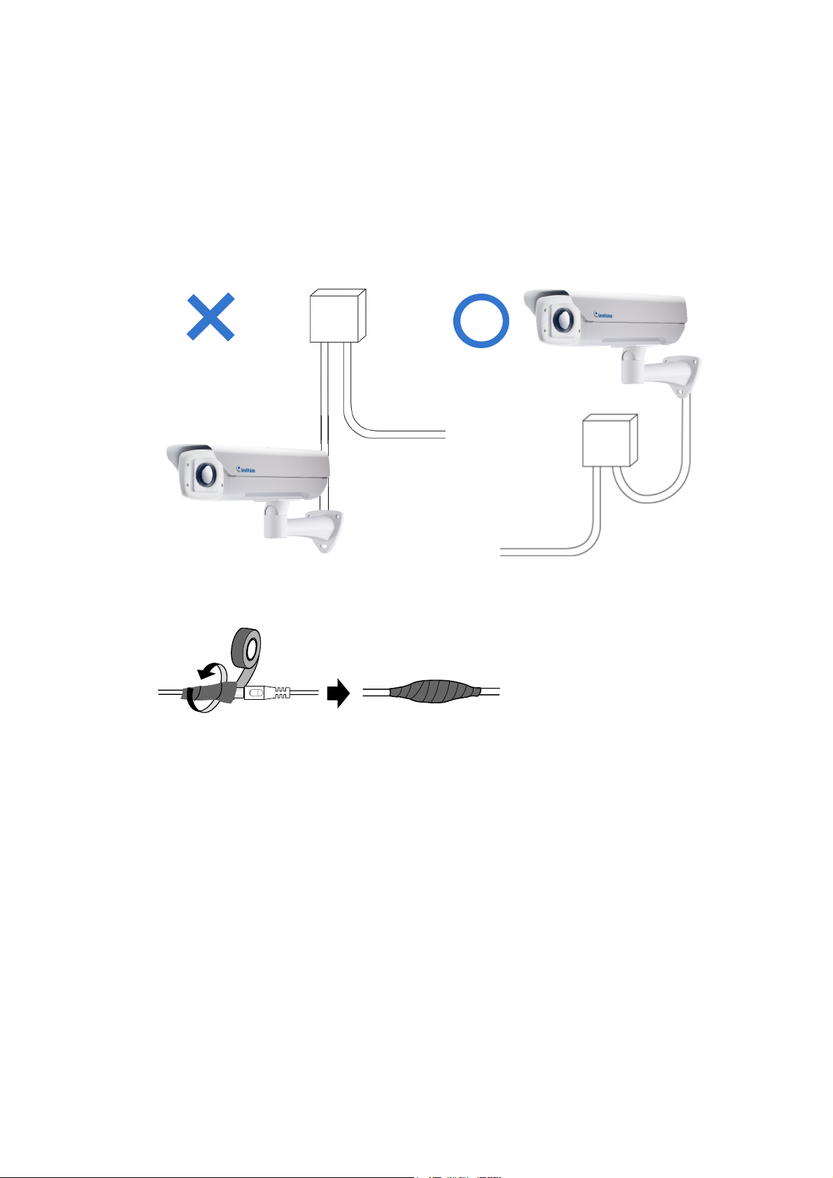
Note for Installing the Camera Outdoor
When installing GV-TM0100 outdoor, mind the following:
1. Set the camera above the junction box to prevent water from entering the camera along
the cables.
2. Waterproof the PoE and power cables with waterproof silicon rubber or the like.
3. To prevent the lens from fogging up, replace the silica gel bag every time you open the
camera, and conceal the gel bag in camera within 2 minutes of exposing to open air. The
silica gel bag loses it effectiveness when the dry camera is opened.
v
Page 8

Chapter 1 Introduction
GV-TM0100 is an outdoor thermal IP camera capable of producing black-and-white
images based on the detected temperature of the people, vehicles and environment.
Unlike traditional cameras that rely on visible light, GV-TM0100 is unaffected by the
lighting conditions and allows you to detect movements even in complete darkness and
backlit scenes.
Ideal for border surveillance and sparsely populated areas, GV-TM0100 can detect
human-sized targets at a distance of 1450 m (4757 ft) and vehicles at 1850 m (6070 ft).
GV-TM0100 can be easily configured through its Web interface and you can record and
play back recordings using the GV-VMS software included in the standard package.
Page 9

1.1 Features
z CIF B/W Uncooled FPA micro bolometer, 25 um pixel size
z Thermal sensitivity of ≤100 mK at f/1,300K
z Spectral range between 8 ~ 14 um
z Single stream from H.264 or MJPEG
z Up to 25 fps at 352 x 288
z 2x digital zoom
z Up to 1450 m (4757 ft) detection range for human targets and 1850 m (1850 ft) for
z Up to 480 m (1575 ft) recognition range for human targets and 920 m (3018 ft) for vehicles
z Ingress protection (IP66)
z DC 12V / PoE (IEEE 802.3af)
z Motion detection
z Privacy mask
z Text overlay
z IP address filtering
z CE, FCC, RCM, RoHS compliant
z Support for iPhone, iPad, Android and 3GPP
z 28 languages on Web interface
vehicles
2
Page 10

1.2 Packing List
• GV-TM0100 • Supporting Rack
Introducti
1
on
• He
• Phill
• GV-IPCAM Software CD / DVD
•
• Warranty Card
x Key
ips Cap Screw x 2
GV-Software DVD
• Rubber
• 12V Power Adapter
Pad for Supporting Rack
3
Page 11

1.3 System Requirement
To access the camera functions and settings through the Web interface, ensure your PC is
in good network connection and uses one of the following Web browsers:
• Microsoft Internet Explorer 7.x or later
• Mozilla Firefox
• Safari
Note:
1.
For the users of Internet Explorer 8 or later, additional settings are required. For
details, see Appendix A
With non-IE browsers,
2.
A. Motion Detection and Text Overlay are not supported.
B. The Play function is only available on the live view window (Figure 3-2).
C. RTSP streaming must be kept as enabled. For more details, see 5.3.5 RTSP.
.
Compatible Software Version
Model Firmware Version GV-VMS Version
GV-TM0100 V1.0 V15.10.1.0 with patch files or later versions
4
Page 12

Introduction
1
1.4 Device Installation
GV-TM0100 can be mounted on the wall using the supplied support rack. Follow the steps
below to install your camera.
1. Place the supporting rack on the wall, mark the locations of the three screw holes, and
drill three holes on the wall.
2. Secure the supporting rack to the camera for wall mount.
A. Place the rubber pad on either of the positions in figure 1-1a or figure 1-1b at the
base of the camera’s housing.
Figure 1-1a
Figure 1-1b
B. Attach the supporting rack to the rubber pad with the screws provided.
Figure 1-2a Figure 1-2b
5
Page 13

3. Secure the supporting rack to the wall using the self-prepared screws.
Figure 1-3
4. Connect the camera to power and network. See 1.5 Connecting the Camera.
5. Access the live view. See Getting Started, Chapter 2.
6. Based on the live view, adjust the angle, zoom and focus of the camera. Loosen the
indicated screw with the supplied hex key and adjust the joint.
Figure 1-4
Tilt Adjustment
6
Figure 1-5
Page 14

Introduction
1
Pan Adjustment
Figure 1-6
7
Page 15

1.5 Replacing the Silica Gel Bag
If you open the camera lid, you must replace the original silica gel bag with a new one.
1. Loosen the screws holding the camera’s lid with a screwdriver.
Figure 1-7
2. Open the camera’s lid and you will find a silica gel bag attached to the interior of the lid.
Figure 1-8
3. Remove the silica bag and place a new bag back to its original position.
4. Fasten the camera’s lid within 2 minutes of replacing the silica gel bag.
IMPORTANT: The silica gel loses its effectiveness when the dry camera is opened. To
prevent the lens from fogging up, replace the silica gel bag every time you open the
camera and conceal the gel bag in the camera within two minutes of exposing to the open
air.
8
Page 16

1.6 Connecting the Camera
1.6.1 Wire Definition
Introduction
1
No. Wire Definition
RJ-45 Ethernet / PoE Connection
1
2-Pin Terminal Block Power
2
Figure 1-9
9
Page 17

1.6.2 Power and Network Connection
GV-TM0100 can connect to power using either the supplied 12V power adaptor or a PoE
adaptor. Follow the steps below to connect your GV-TM0100 to power and network.
1.6.2.1 PoE Connection
Use an optional GV-PA191 PoE Adapter to connect the camera to the power and network
at the same time. Two Ethernet cables are required for the connection.
1. Insert one end of the Ethernet cable into the PoE 10/100 port on the GV-PA191.
Connect the other end of the cable to your camera.
2. Insert one end of the second Ethernet cable into the LAN 10/100 port on the GV-
PA191. Connect the other end of the cable to the hub or router connecting to your
computer.
Figure 1-10
3. Insert the supplied GV-PA191 power adaptor into the terminal block on the GV-PA191.
4. Connect the AC power cord to the power outlet.
5. When the Power LED on the front panel of the GV-PA191 turns green, you are ready
to access the live view, adjust the image clarity and configure the basics. See Getting
Started, Chapter 2.
10
Page 18

Introduction
1
1.6.2.2 Power Adapter Connection
Besides PoE connection, you can use the supplied 12V power adaptor to connect the
camera to the power.
1. Plug the 12V power adapter to the 2-pin terminal block on the camera.
Figure 1-11
2. Connect the DC power cord to a power source.
3. Use a standard network cable to connect GV-TM0100 to your network.
11
Page 19

Chapter 2 Getting Started
This section provides basic information to get the camera working on the network.
2.1 Checking the IP Address
By default, an unused IP address is automatically assigned by the DHCP server to the
camera when connecting to the network. Follow the steps below to look up the IP address
and access the Web interface.
1. Install the GV-IP Device Utility program included on the Software CD/DVD.
Note: The PC installed with GV-IP Device Utility must be under the same LAN with the
camera you wish to configure
2. On the GV-IP Utility window, click the button to search for the IP devices
connected in the same LAN. Click the Name or Mac Address column to sort.
3. Find the camera with its Mac Address, click on its IP address and select Web Page.
Figure 2-1
12
Page 20

4. The login page appears.
Getting Started
2
Figure 2-2
5. Type the default ID and password admin and click Apply to login.
13
Page 21

2.2 Changing the IP Address
To assign a static IP address or establish a connection to your ISP, log in the Web interface
to access the network setting page.
Note: If your router does not support DHCP, the default IP address will be 192.168.0.10.
In this case, it is strongly suggested that you modify the IP address to avoid the IP
address conflict with the other GV-IP device on the same LAN.
1. Open your Web browser, and type the IP address of the camera or the default IP
address http://192.168.0.10
2. In both Login and Password fields, type the default value admin. Click Apply.
3. In the left menu, select Network and then LAN to begin the network settings.
Figure 2-3
4. To assign a static IP address, select Static IP address. Type IP Address, Subnet
Mask, Router/Gateway, Primary DNS and Secondary DNS in the Configure
connection parameters section.
5. Click Apply. The camera is accessible by entering the assigned IP address on the
Web browser.
14
 Loading...