

Page 1

GV-SNVR System
User’s ManualUser’s Manual
SNVRV12-UM-A
Page 2

© 2015 GeoVision, Inc. All rights reserved.
Under the copyright laws, this manual may not be copied, in whole or in part,
without the written consent of GeoVision.
Every effort has been made to ensure that the information in this manual is
accurate. GeoVision, Inc. makes no expressed or implied warranty of any kind
and assumes no responsibility for errors or omissions. No liability is assumed
for incidental or consequential damages arising from the use of the information
or products contained herein. Features and specifications are subject to
change without notice.
Note: No memory card slot or local storage function for Argentina.
GeoVision, Inc.
9F, No. 246, Sec. 1, Neihu Rd.,
Neihu District, Taipei, Taiwan
Tel: +886-2-8797-8377
Fax: +886-2-8797-8335
http://www.geovision.com.tw
Trademarks used in this manual: GeoVision, the GeoVision logo and GV
series products are trademarks of GeoVision, Inc. Windows and Windows XP
are registered trademarks of Microsoft Corporation.
November 2015
Page 3
Preface
Welcome to the GV-SNVR system, GV-SNVR0410F / GV-SNVR0400F /
GV-SNVR1600, User’s Manual.
The GV-SNVR system has a series of models designed to meet different needs.
This manual is designed for the following models and firmware versions:
Models Firmware Version
GV-SNVR0410F (Coming) V1.20
GV-SNVR0400F V1.10
GV-SNVR1600 V1.20
i
Page 4

Contents
Chapter 1 Introduction ...........................................................................................1
1.1 Features...................................................................................................................2
1.2 Models .....................................................................................................................2
1.3 Packing List and Package........................................................................................ 3
1.3.1 GV-SNVR Single Package............................................................................ 3
1.3.2 Bundled Package for GV-SNVR0400F ......................................................... 5
1.4 Compatible Products and System Requirements .................................................... 6
1.4.1 Supported GV-IP Cameras ........................................................................... 6
1.4.2 Supported GeoVision Applications................................................................ 6
1.4.3 System Requirements................................................................................... 7
1.5 Options .................................................................................................................... 7
1.6 Overview..................................................................................................................8
1.6.1 Front View..................................................................................................... 8
1.6.2 Rear View ....................................................................................................11
Chapter 2 Getting Started ....................................................................................14
2.1 Installation ............................................................................................................. 14
2.1.1 GV-SNVR0400F.......................................................................................... 14
2.1.2 GV-SNVR1600............................................................................................ 17
2.2 Connecting the GV-SNVR ..................................................................................... 20
2.2.1 Network Connection for GV-SNVR1600 ..................................................... 22
2.3 Setting Up GV-IP Camera ..................................................................................... 23
2.3.1 Automatically Setting Up GV-IP Camera .................................................... 23
2.3.2 Manually Connecting GV-IP Camera .......................................................... 25
2.3.3 Changing Camera IP Address and Assigning Channels............................. 26
2.4 Formatting the Hard Drive ..................................................................................... 27
2.5 Main Screen .......................................................................................................... 29
2.6 Enabling Recording ............................................................................................... 31
2.7 Playing Back Video................................................................................................ 31
2.8 Live Monitoring ...................................................................................................... 32
2.8.1 Snapshot..................................................................................................... 32
2.8.2 Audio........................................................................................................... 33
2.8.3 PTZ Control................................................................................................. 34
Chapter 3 System Configuration.........................................................................36
3.1 Camera .................................................................................................................. 36
3.2 Recording............................................................................................................... 38
3.3 Network.................................................................................................................. 39
ii
Page 5

3.4 Storage................................................................................................................... 43
3.5 Display ................................................................................................................... 44
3.6 Service ................................................................................................................... 45
3.7 System ................................................................................................................... 47
Chapter 4 Video Playback....................................................................................50
4.1 Timeline Player ...................................................................................................... 50
4.2 Recording Backup.................................................................................................. 52
Chapter 5 Remote Access to the GV-SNVR........................................................53
5.1 Accessing through Web Browser........................................................................... 54
5.1.1 Live View Screen ........................................................................................ 55
5.1.2 Snapshot of Live Video ............................................................................... 57
5.1.3 Picture-in-Picture View................................................................................ 58
5.1.4 Picture-and-Picture View ............................................................................ 59
5.1.5 Digital PTZ Control...................................................................................... 60
5.2 Accessing through Mobile Device.......................................................................... 61
5.3 Accessing through GV-Edge Recording Manager ................................................. 61
5.4 Accessing through GV-Control Center................................................................... 62
Chapter 6 Advanced Applications.......................................................................63
6.1 Upgrading System Firmware ................................................................................. 63
6.2 Using the GV-IP Device Utility ............................................................................... 64
6.2.1 Looking up the IP Address.......................................................................... 64
6.2.2 Accessing the Live View ............................................................................. 64
6.2.3 Upgrading System Firmware ...................................................................... 65
6.2.4 Backing up and Restoring Settings............................................................. 66
Specifications..........................................................................................................68
Appendix ..............................................................................................................72
iii
Page 6
Introduction
1
Chapter 1 Introduction
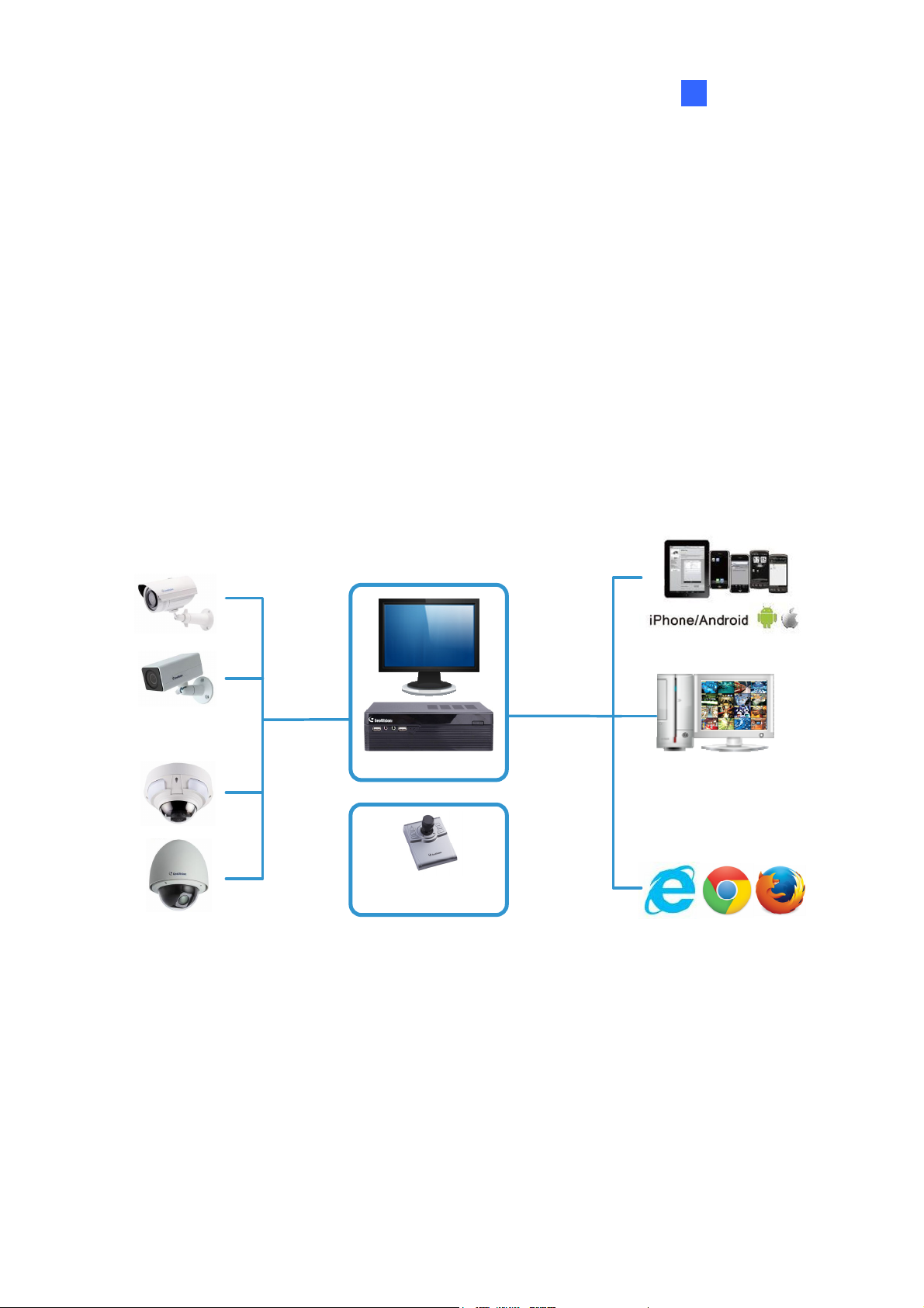
The GV-SNVR system is a Linux-embedded Standalone Network Video Recorder which
records video files directly to the internal hard drive, supporting up to 4 / 16 channels of
GV-IP Cameras for network surveillance. With the feature of a Full HD HDMI video output,
the GV-SNVR eliminates the need for a separate PC to view and play back video from the
unit. Its four / five USB ports allow you to connect a storage device to import or export
system settings, update firmware, save snapshot files and back up video in AVI format.
Optionally, you can connect a GV-Joystick V2 to control PTZ cameras. Moreover, you can
remotely access the live view through mobile devices or Web browsers with advanced
video features.
Up to 4 / 16
GV-IP Cameras
Access
Live View
Play back
Recording
GV-SNVR
+
GV-Joystick V2
(for PTZ Camera)
Figure 1-1
Up to 10 / 34
Connections
Access
Live View
GV-Edge Recording Manager
GV-Control Center
GV-Vital Sign Monitor
GV-Center V2
1
Page 7

1.1 Features
․ 4-Channel video recording (for GV-SNVR0410F / 0400F)
․ 16-Channel video recording (for GV-SNVR1600)
․ Automatic search and set-up for IP cameras
․ Up to 2560 x 1920 for the first channel (for GV-SNVR1600)
․ Up to 1920 x 1080 per channel
․ Dual streams support
․ Continuous, motion and scheduled recordings
․ Timeline playback
․ Multi-channel playback
․ Display of HDD status and system temperature
․ DST (Daylight Saving Time) support
․ NTP (Network Time Protocol) support
․ GeoVision DDNS server support
․ E-mail notification for recording error and password retrieval
․ Recording export
․ Remote live view through Web browser
․ PTZ control using GV-Joystick V2 or on-screen panel
․ 1080p HDMI video output
․ 1 SATA HDD drawer (3.5”) for up to 4 TB storage (for GV-SNVR0410F / 0400F)
․ 4 SATA HDD drawer (3.5”) for up to 16 TB storage (for GV-SNVR1600)
․ Smart device access (iOS and Android)
․ Support for 13 languages
1.2 Models
The GV-SNVR has the following models:
GV-SNVR0410F
GV-SNVR0400F
GV-SNVR1600
2
- Supports 1 SATA HDD (3.5”)
- Records up to 4 IP channels
- Supports 4 SATA HDD (3.5”)
- Records up to 16 IP channels
Page 8
Introduction
1
1.3 Packing List and Package
You can choose to purchase a GV-SNVR package or a bundled package which includes 4
GV-Target IP Camera of your choice, and with or without a GV-PoE switch.
Package Options:
• Single Package for GV-SNVR0410F
• Single Package for GV-SNVR0400F
• Single Package for GV-SNVR1600
• Bundled Package for GV-SNVR0410F
• Bundled Package for GV-SNVR0400F
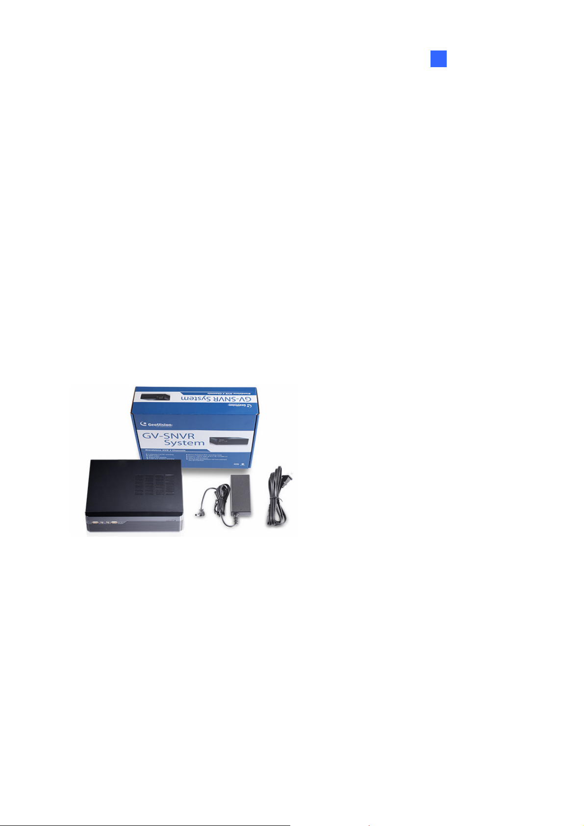
1.3.1 GV-SNVR Single Package
GV-SNVR0410F
1. GV-SNVR0410F
2. AC Power Cord
3. AC/DC Adapter
(DC 52V, 2.5A, 90 W)
4. Screw x 6 (for HDD)
5. SATA Cable
6. USB Mouse
7. Firmware CD/DVD
8. Software CD/DVD
9. Quick Start Guide
10. Warranty Card
3
Page 9
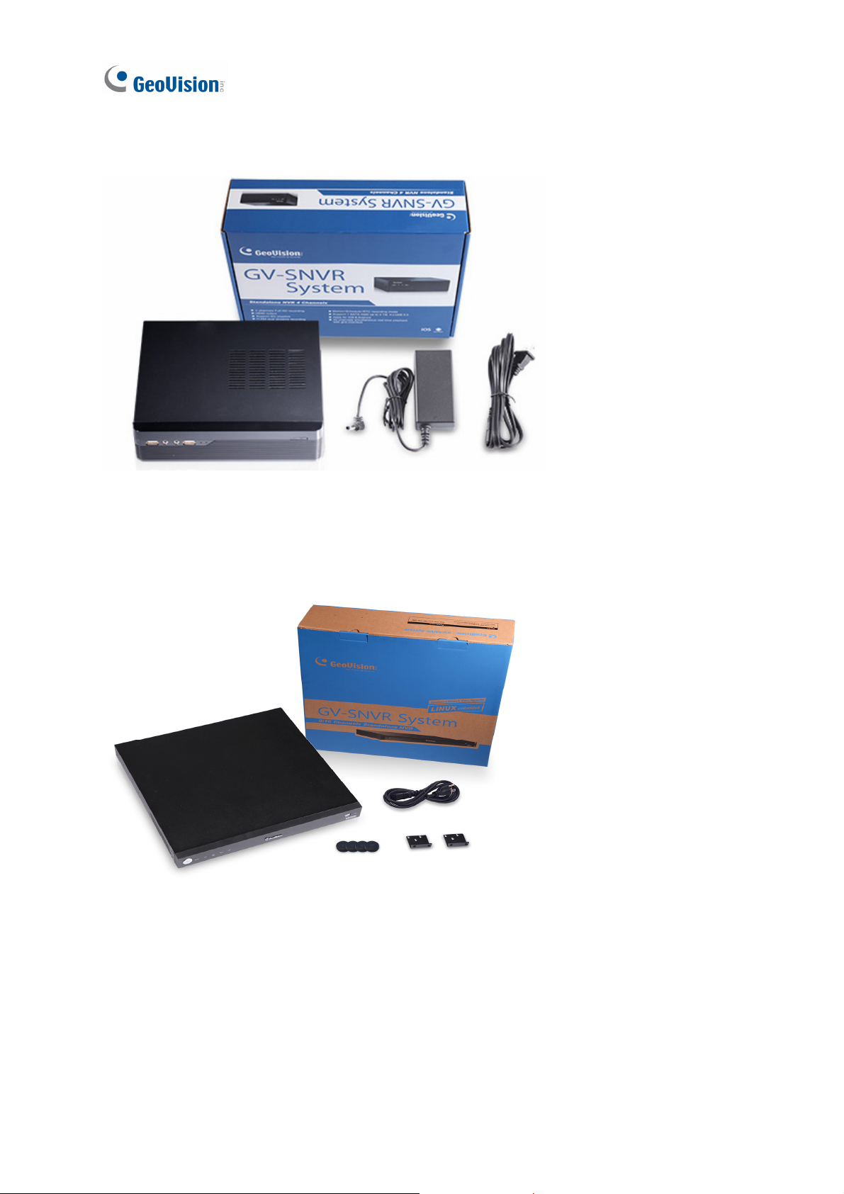
GV-SNVR0400F
1. GV-SNVR0400F
2. AC Power Cord
3. AC/DC Adapter
(DC 19V, 3.42A, 65 W)
4. Screw x 6 (for HDD)
5. SATA Cable
6. USB Mouse
7. Firmware CD/DVD
8. Software CD/DVD
9. Quick Start Guide
GV-SNVR1600
10. Warranty Card
1. GV-SNVR1600
2. AC Power Cord
3. SATA Cable x 4
4. HDD Mounting Bracket Kit (4
pairs and 32 screws included)
5. Rack Mount Kit (2 L-shaped
brackets and 6 screws
included)
6. Rubber Foot x 4
7. USB Mouse
8. Firmware CD/DVD
4
9. Software CD/DVD
10. Quick Start Guide
11. Warranty Card
Page 10
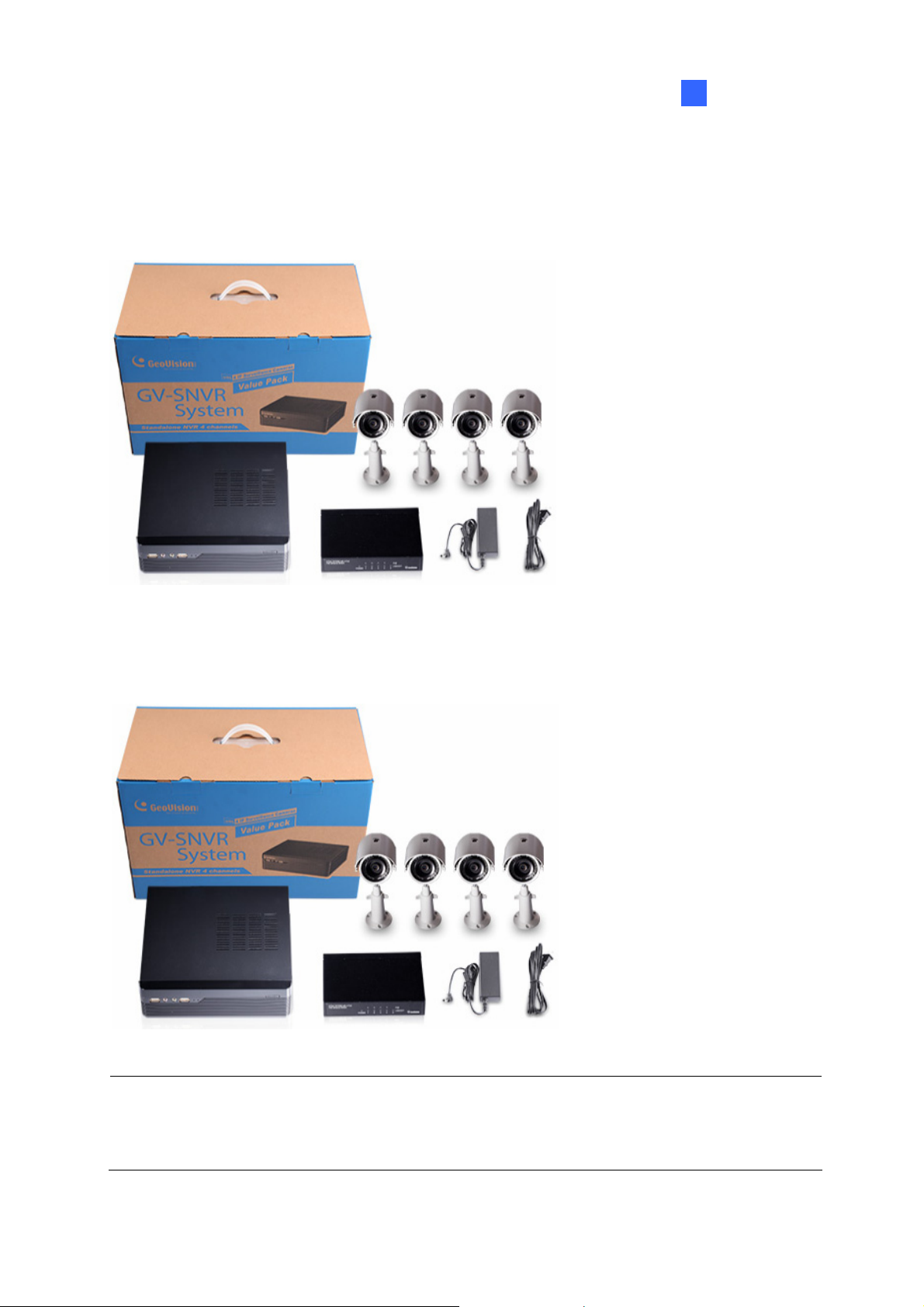
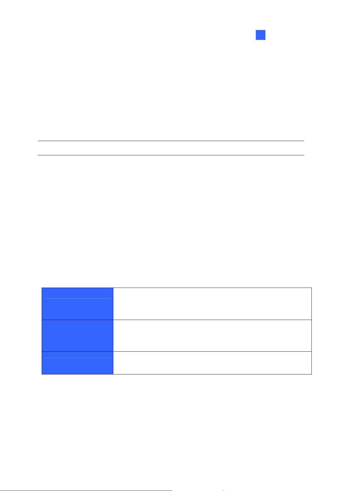
1.3.2 GV-SNVR Bundled Package
Introduction
1
GV-SNVR0410F
GV-SNVR0400F
1. GV-SNVR0410F Package x1
2. Target IP Camera x 4
1.GV-SNVR0400F Package x 1
2. Target IP Camera x 4
3.GV-POE0400 x 1
Note: For the Target IP Camera, select any 4 models from GV-EBL1100 / 2100,
GV-EBX1100 / 2100, GV-EDR1100 / 2100, GV-EFD1100 / 2100. For more information,
contact our sales representatives.
5
Page 11

1.4 Compatible Products and System Requirements
1.4.1 Supported GV-IP Cameras
The GV-SNVR is compatible with the following GV-IP Cameras:
․ GV-Target Series IP Camera (Firmware V1.0 or later)
․ GV-SD220/220-S (Firmware V1.04 or later)
․ All the other GV-IP Cameras (Firmware V2.11 or later) EXCEPT the models below:
GV-BX110
GV-BX12201 (Only for GV-SNVR1600)
GV-BL110
GV-Fisheye IP Camera (Only for GV-SNVR0410F / 0400F)
GV-FER12203
GV-MFD110
GV-PT110
GV-PTZ010D
GV-SD010/200/200-S
GV-SD2411 (Only for GV-SNVR1600)
IMPORTANT:
1. The GV-SNVR supports the recording frame rate of up to 30 fps only.
2. The GV-SNVR supports a total bandwidth of up to 50 Mbps for GV-SNVR0410F /
0400F and 100 Mbps for GV-SNVR1600.
1.4.2 Supported GeoVision Applications
The GV-SNVR is compatible with the following applications:
․ GV-Edge Recording Manager (Windows Version V1.1.0.0 or later)
․ GV-Control Center (V3.3.0.0 or later)
․ GV-Center V2 (V15.10 or later)
․ GV-Vital Sign Monitor (V15.10 or later)
․ GV-Eye (V2.0 or later)
6
Page 12
Introduction
1
1.4.3 System Requirements
Recommended Hard Disks
GV-SNVR0410F / GV-SNVR0400F supports 1 SATA HDD (3.5”) with up to 4 TB capacities,
and GV-SNVR1600 supports 4 SATA HDD (3.5”) with total up to 16 TB capacities. For system
efficiency, it is recommended to use the enterprise-level hard disk drives instead of
desktop-level or green HDD. For tested hard disk drives, see Appendix.
Note: The GV-SNVR does not support the 2.5” SATA HDD.
Supported Web Browsers
1. Internet Explorer 8 or later
2. Google Chrome 33.0 or later
3. Mozilla Firefox 28.0 or later
1.5 Options
Optional devices can expand your GV-SNVR’s capabilities and versatility. Contact your
dealer for more information.
The GV-Joystick V2 facilitates the PTZ camera control. It can be
GV-Joystick V2
GV-POE Switch
Slide Rail Kit
plugged into the GV-SNVR for independent use to empower the
operation of PTZ cameras.
The GV-POE Switch is designed to provide power along with
network connection for IP devices. The GV-POE Switch is available
in various models with different numbers and types of ports.
The Slide Rail Kit is used to mount a rail for the GV-SNVR1600 in a
19” cabinet.
7
Page 13
1.6 Overview
1.6.1 Front View
1.6.1.1 GV-SNVR0410F
3
1
No. Name Function
USB 2.0 Ports Connects to a keyboard, mouse, storage device or GV-Joystick V2.
1
2 Default Button
Power LED Shows constant blue when the power is supplied for the device.
3
2
Restores the device to default settings. Press the button for 15
seconds to load default.
5
4
Figure 1-1
6
Shows constant red when the following situations occur:
4 HDD Error LED
Audio In Not functional.
5
Power Input Connects to power supply.
6
8
․ No hard drive is installed.
․ The hard drive is not formatted.
․ The hard drive fails.
Page 14
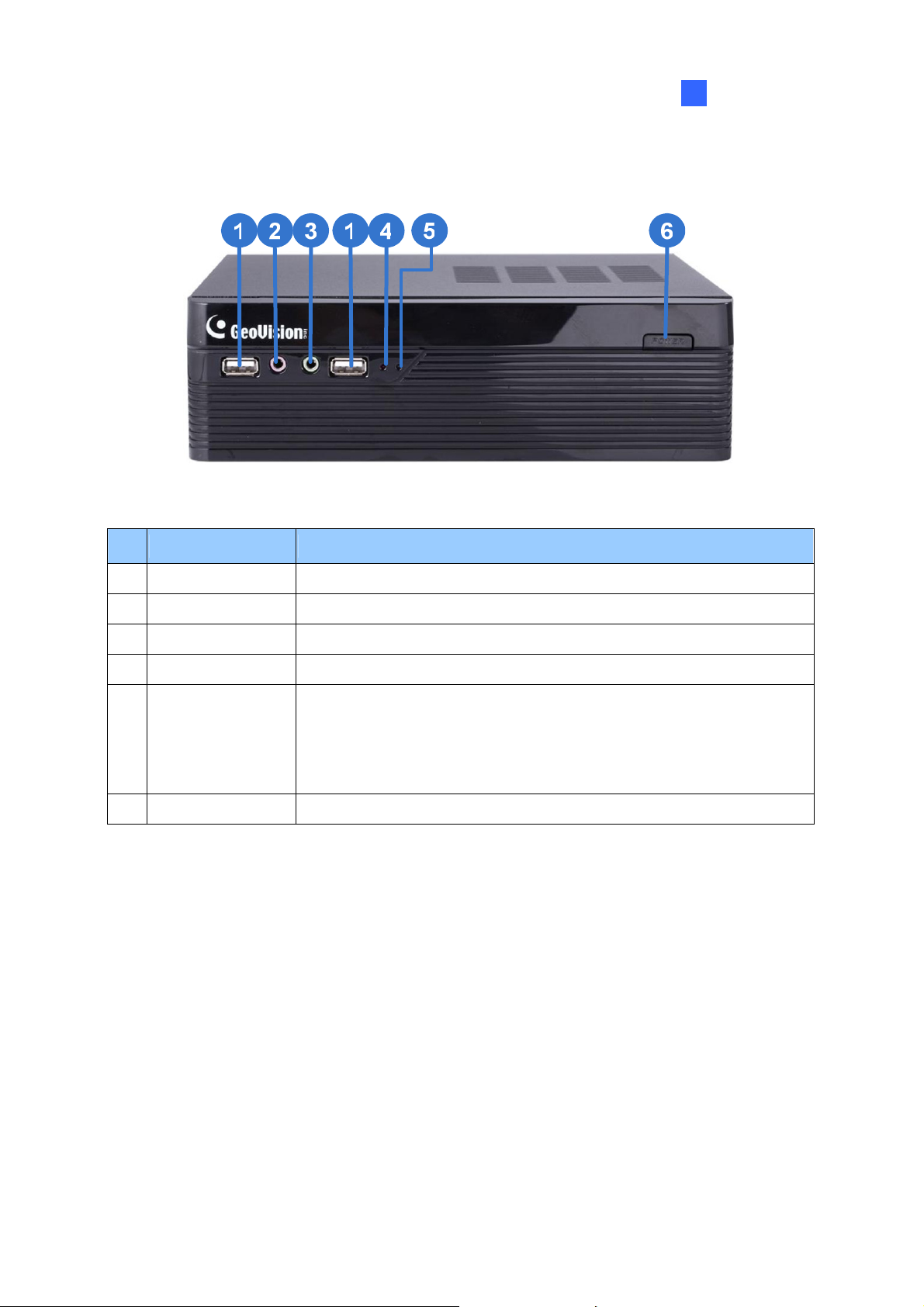
1.6.1.2 GV-SNVR0400F
Figure 1-2
Introduction
1
No. Name Function
USB 2.0 Port Connects to a keyboard, mouse, storage device or GV-Joystick V2.
1
Audio In Not functional.
2
Audio Out Connects to a speaker.
3
Power LED Shows constant blue when the power is supplied for the device.
4
Shows constant red when the following situations occur:
․ No hard drive is installed.
5 HDD Error LED
․ The hard drive is not formatted.
․ The hard drive fails.
Power Button Turns on/off the power.
6
9
Page 15

1.6.1.3 GV-SNVR1600
2
1
No. Name Function
Power Button Turns on/off the power.
1
Power LED Shows constant blue when the power is supplied for the device.
2
HDD Status LED Flashes blue when the hard drive is writing or reading data.
3
4 HDD Error LED
3
4
6
5
Figure 1-3
Shows constant red when the following situations occur:
․ No hard drive is installed.
․ The hard drive is not formatted.
7
․ The hard drive fails.
WAN LED Flashes blue when the WAN port is receiving activity.
5
LAN LED Flashes blue when the LAN port is receiving activity.
6
USB 2.0 Port Connects to a keyboard, mouse, storage device or GV-Joystick V2.
7
10
Page 16

1.6.2 Rear View
1.6.2.1 GV-SNVR0410F
Introduction
1
1
2
3
Figure 1-4
4
No. Name Function
Megabit PoE Ports Connects to cameras and provides power.
1
Gigabit Ethernet Port Connects to the network.
2
Audio Out Connects to a speaker.
3
HDMI Output Connects to a HD TV.
4
5 USB 2.0 Port
Connects to a keyboard, mouse, storage device or GV-Joystick
V2.
5
11
Page 17

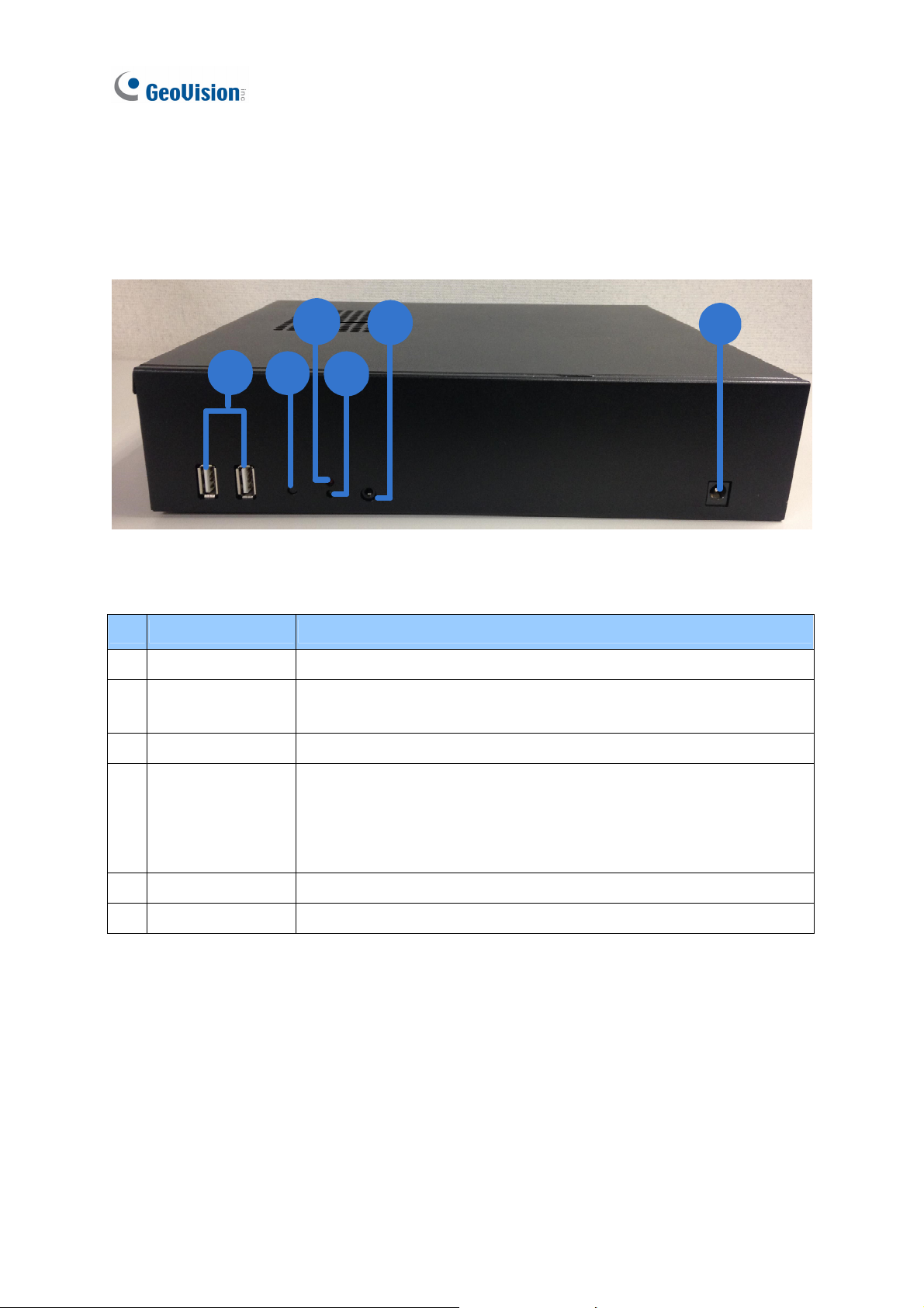
1.6.2.2 GV-SNVR0400F
Figure 1-5
No. Name Function
Gigabit Ethernet Port Connects to the network.
1
HDMI Output Connects to a HD TV.
2
3 USB 2.0 Port
4 Default Button
Power Input Connects to power supply.
5
Connects to a keyboard, mouse, storage device or GV-Joystick
V2.
Restores the device to default settings. Press the button for 15
seconds to load default.
12
Page 18

1.6.2.3 GV-SNVR1600
Figure 1-6
No. Name Function
Introduction
1
Audio Microphone In Port Not functional.
1
VGA Monitor Output Connects to a VGA monitor.
2
HDMI Port Connects to a HD TV.
3
4 USB 2.0 Port x 4
Power Input Connects to power supply.
5
Gigabit Ethernet Port (LAN) Connects to the network.
6
Gigabit Ethernet Port (WAN) Connects to the network.
7
Audio Line Out Port Connects to a headphone.
8
Audio Line Out Port Connects to a speaker.
9
Connects to a keyboard, mouse, storage device or
GV-Joystick V2.
Note: When the two Ethernet ports (No. 6 and No. 7) are used together, one is LAN port and
the other is WAN port.
13
Page 19

Chapter 2 Getting Started
2.1 Installation
The GV-SNVR uses SATA hard drive for video data storage. Before recording, be sure to
install the hard drive.
2.1.1 GV-SNVR0410F/ GV-SNVR0400F
Installing the Hard Drive
Follow the steps below to install the hard drive to the GV-SNVR0410F / GV-SNVR0400F.
1. Unscrew the two screws on the rear panel and remove the cover.
Figure 2-1
2. Unscrew the drive drawer and take it out from the device.
14
Figure 2-2
Page 20

Getting Started
2
3. Place the hard drive in the drive drawer as below by aligning the three holes.
ٛٛٛٛٛٛٛ
Figure 2-3
4. Secure the hard drive with the drive drawer using the supplied 6 screws (3 screws on
each side).
ٛ
Figure 2-4
5. Connect the SATA Power Cable and Data Cable to the hard drive.
Figure 2-5
15
Page 21

6. Put the drive drawer back in the device and secure the two screws on the drive drawer
(Figure 2-2).
7. Assemble the cover with the device by tightening the screws on rear panel (Figure 2-2).
The hard drive is now ready to use.
16
Page 22

Getting Started
2
2.1.2 GV-SNVR1600
Installing the Hard Drive
Follow the steps below to install the hard drive to the GV-SNVR1600.
1. Loosen the 6 screws and remove the cover.
Figure 2-6
2. Assemble the mounting brackets with the hard drive and tighten the screws on both sides.
Figure 2-7
Note: Each mounting bracket is labeled L or R for recognition. Align the mounting bracket
with the holes on the hard drive and make sure it is secured to the correct side.
17
Page 23

3. Align the mounting bracket with the holes inside the unit.
Figure 2-8
4. Tighten the 4 screws on the side of the hard drive.
Figure 2-9
5. Connect the SATA Power Cable and Data Cable to the hard drive.
18
Figure 2-10
Page 24

Getting Started
2
6. To install more HDDs, repeat the steps above.
7. Place the cover back and tighten the screws.
The hard drive is now ready for use.
Installing the L-Shaped Brackets
Tighten the 6 screws to secure and attach the 2 L-shaped brackets to each side of
GV-SNVR1600.
Figure 2-11
19
Page 25

2.2 Connecting the GV-SNVR
Follow the steps below to connect the GV-SNVR.
1
6
3
2
4
5
GV-SNVR0410F
20
3
1
2
4
5
GV-SNVR0400F
Page 26

Getting Started
2
4
3
2
5
1
GV-SNVR1600
Figure 2-12
1. Connect the GV-SNVR to power.
2. Connect the GV-SNVR to the LAN port using the Ethernet cable.
3. Connect a speaker to the Audio Line Out port.
4. Connect a HDTV to HDMI connector for video output. For GV-SNVR1600, optionally
connect t a VGA monitor to the D-Sub connector for dual-monitor display.
5. Connect the mouse and the keyboard to the USB ports.
6. Only for GV-SNVR0410F, connect the GV-SNVR to cameras using Ethernet cables.
Press the power button to turn on the GV-SNVR.
Note:
1. The GV-SNVR is DHCP enabled. When it is connected to the network, it will be
automatically assinged an IP address.
2. For GV-SNVR1600, the monitor used for VGA output must be capable of having a
screen resolution of 1080p.
21
Page 27

2.2.1 Network Connection for GV-SNVR1600
There are two network ports, LAN and WAN, for the GV-SNVR1600. If both network ports are
used simultaneously, only the WAN port can be connected to the Internet. Therefore, it is
recommended to connect the devices as below.
Internet
GV-IP Cameras
LAN
WAN
GV-SNVR1600
Figure 2-13
1. Connect GV-IP Cameras to the GV-SNVR1600 through the LAN port.
2. Connect GV-SNVR1600 to the Internet through the WAN port.
Note: When the LAN and WAN ports are used together, the Auto Search function is only
supported by the LAN port. To connect to GV-IP Cameras under the WAN, you can add the
cameras manually.
IMPORTANT: It is required to divide LAN and WAN networks into different subnets or
segments; otherwise, your network will fail. For details, see 3.3 Network.
22
Page 28

Getting Started
2
2.3 Setting Up GV-IP Camera
After installing the IP cameras under the same LAN with the GV-SNVR, you can now add the
cameras to GV-SNVR.
2.3.1 Automatically Setting Up GV-IP Camera
GV-SNVR0410F
To automatically set up the IP cameras, follow the steps below.
1. Power on GV-SNVR0410F.
2. Connect GV-SNVR0410F and cameras with Ethernet cables (No.2, Figure 2-12).
3. Within one minute, live view appears when GV-SNVR0410F is connected with the
cameras.
GV-SNVR0400F / GV-SNVR1600
To automatically set up the IP cameras, follow the steps below.
1. Power on the GV-SNVR. It automatically searches and lists the IP cameras under the
same LAN.
2. You are prompted with a dialog box asking if you want to automatically assign IP address.
The automatic assignment will only apply on the cameras with IP address 192.168.0.10.
Figure 2-14
23
Page 29

3. Click Apply. The GV-SNVR assigns unused IP addresses to the cameras in an
ascending numerical order and enables the connection.
Figure 2-15
Upon successful connection, the status displays “Connected”, with the resolution and
bandwidth being displayed in the correspondent columns. Close the Camera page to access
the live view.
IMPORTANT:
1. By default, GV-IP Cameras use the IP address 192.168.0.10. The GV-SNVR will
automatically assign unused IP addresses to these cameras to avoid IP address conflict with
others under the same LAN.
2. The GV-SNVR connects to the IP cameras with the default ID and password admin. If the IP
camera uses a different ID and password, click the Edit icon
and type the correct login
information.
3. The GV-SNVR supports a total bandwidth of up to 50 Mbps for GV-SNVR0410F / 0400F and
up to 100 Mbps for GV-SNVR1600. The total bandwidth can be found in the top-right corner
of the camera list.
24
Page 30

Getting Started
2
2.3.2 Manually Connecting GV-IP Camera
Only for GV-SNVR0400F and GV-SNVR1600, you can manually add the GV-IP Camera to
the camera list, follow the steps below.
1. On the Camera page, click the Add Cameras button.
2. Type the IP Address, Username and Password of the desired IP camera. Keep the
default Port 10000 or modify if necessary.
Figure 2-16
3. Click Apply to add the IP camera.
4. To add multiple cameras, repeat step 2, type the number of cameras you want to create
in the Add Camera column.
․ To duplicate camera with same IP address but different ports, type the IP address
and click the Duplicate column of Port.
․ To duplicate camera with same port number but different IP addresses, type the port
number and click the Duplicate column of IP Address.
5. To connect the GV-SNVR with the added cameras, click the box next to the CH column
on the Camera page.
Figure 2-17
25
Page 31

6. To delete the added IP camera, click the Delete button of the camera on the
Camera page.
2.3.3 Changing Camera IP Address and Assigning Channels
On the Camera page, you can change the IP address of the connected cameras by clicking
on the IP address.
You can also re-assign the camera to another channel. For example, to change the camera
on Channel 1, deselect the connected camera on Channel 1 and select another camera for
connection. The selected camera is now assigned to Channel 1.
Figure 2-18
26
Page 32

Getting Started
2
2.4 Formatting the Hard Drive
After installing the hard drive to GV-SNVR, you need to format the hard drive before enabling
the monitoring.
1. On the main screen, click the Setting button.
Figure 2-19
2. Select Storage.
Figure 2-20
3. Click Format. This dialog box appears.
Figure 2-21
4. Click Execute to format the hard drive.
27
Page 33

When the hard drive is successfully formatted, its icon should be marked with a green tick,
and the “Normal” message appears. The information of operating temperature, hard drive
status and total time in use is also displayed.
Figure 2-22
Note: When the hard drive status displays other value instead of 0, replace the hard drive
with a new one to ensure proper video recording.
28
Page 34

Getting Started
2
2.5 Main Screen
Close the Camera page to see the connected channels on the main screen. Here we use
GV-SNVR0400F for illustration.
Figure 2-23
No. Name Description
Indicates the camera name. The column changes from gray to red
1 Camera Name
when the recording is enabled. See Camera Name in 3.1 Camera.
2 System Brings up the options: Log Out and Shutdown.
Accesses the following setting pages:
․ Camera (see 3.1 Camera)
․ Recording (see 3.2 Recording)
․ Network (see 3.3 Network)
3 Setting
․ Storage (see Chapter 2.4 Formatting the Hard Drive)
․ Display (see 3.5 Display)
․ Service (see 3.6 Service)
․ System (see 3.7 System)
4 Record Starts/Stops monitoring.
Division & Page
5
Up / Down
Selects screen divisions and switch between cameras in single
division.
29
Page 35

6 Playback Displays the playback panel.
7 Date / Time Displays the current date and time.
8 Device Name
Displays the device name of GV-SNVR. See Device Name in 3.7
System.
9 Temperature Displays the current temperature.
10 Model Name Displays the model name of GV-SNVR.
30
Page 36

Getting Started
2
2.6 Enabling Recording
To start recording, click the Record button (No. 4, Figure 2-23) and select a camera. To
enable recording for all the connected cameras, select Start All Monitoring.
By default, the GV-SNVR records with the Round-the-clock mode and H.264 codec. The
default recording resolution depends on the settings of each camera.
․ To change recording mode, see 3.2 Recording.
․ To change video resolution, see 3.1 Camera.
2.7 Playing Back Video
You can instantly play back the recorded video without interrupting the monitoring and
recording.
․ To instantly play back the recording of one single channel, click the Camera Name
(No. 1, Figure 2-23), select Instant Playback.
․ To instantly play back the recording of all channels, click the Playback button
(No. 6, Figure 2-23).
Note: For details on playing back the recording, see Chapter 4 Video Playback.
31
Page 37

2.8 Live Monitoring
GV-SNVR0410F / GV-SNVR0400F
On the main screen, the live view of connected cameras is displayed in 4 divisions by default.
You can click the Division button
Optionally, click on the live view of desired camera to switch to full screen.
Figure 2-24
(No. 5, Figure 2-23) and select 1 or 4 Division.
GV-SNVR1600
On the main screen, the live view of connected cameras is displayed in 16 divisions by
default. You can click the Division button
on the live view of desired camera to switch to full screen.
and select 1, 4 or 9 Division. Optionally, click
Figure 2-25
2.8.1 Snapshot
To take a snapshot of live or playback video, follow the steps below.
1. Connect an USB storage device of FAT32 format to the GV-SNVR.
2. Click the camera name of desired camera and select Snapshot. The message
“Snapshot Success” pops up when the captured image is successfully saved to the USB
storage device.
Each image is automatically saved in JPEG format with a file name indicating the date and
time of snapshot.
32
Page 38

Getting Started
2
2.8.2 Audio
To enable the audio function on live video, follow the steps below.
Note: To listen to the audio, make sure the Enable Audio function is applied for the
camera. For details, see 3.1 Camera.
1. Click the live view of the desired camera to switch to full screen.
2. Click the camera name and select Speaker. The audio icon
camera name, and the audio is now accessible.
Figure 2-26
appears beside the
33
Page 39

2.8.3 PTZ Control
To enable the PTZ function on live video, click the camera name of desired camera and
select Enable PTZ. The PTZ control panel appears at the lower-right corner of the live view.
Note: The option is only available for the cameras supporting PTZ functions.
Figure 2-27 Figure 2-28
Home: Brings the PTZ live view back to the Home position.
Pan/Tilt Control: Allows the camera to pan and tilt to any angle.
Zoom Control: Allows the camera to zoom in or out.
Focus Control: Adjusts the camera to focus in or out.
Preset Option: Moves the camera to a preset point by entering a preset number using
the onscreen keypad.
To enable PTZ control, you can also use the GV-Joystick V2, a plug-and-play device used to
pan, tilt, zoom and focus a PTZ camera. When the GV-Joystick V2 is connected to the USB
port on the GV-SNVR, the Joystick icon
will appear beside the camera name.
34
Figure 2-29
Page 40

Getting Started
2
For details on the GV-Joystick V2, see GV-Joystick V2 User’s Manual.
Note: The GV-SNVR does not support GV-Keyboard.
Digital PTZ Function
For non-PTZ cameras, the Digital PTZ (DPTZ) function allows you to simulate the PTZ
movement on the screen.
Note: The DPTZ function is only available for GV-SNVR1600.
To enable the DPTZ function on live video, click the camera name of desired camera and
select Enable Digital PTZ. The PTZ control panel appears at the lower-right corner of the
live view.
Click the Zoom In button first and then click Tilt and Pan buttons to move the camera view.
Figure 2-30 Figure 2-31
Home: Brings the DPTZ live view back to the Home position.
Pan/Tilt Control: Allows you to pan and tilt on the live view.
Zoom Control: Allows you to zoom in or out on the live view.
Note:
1. The Focus Control and Preset functions are not supported.
2. The DPTZ function is only available for non-PTZ cameras.
35
Page 41

Chapter 3 System Configuration
This section introduces the settings of camera, video recording, network, storage, display,
service and system.
3.1 Camera
To access the camera settings, click the Edit button of the camera on the Camera page.
Figure 3-1
The Camera Settings page appears.
Figure 3-2
Camera Name: Type a desired name for the camera.
Username: Type the username of the camera. The default is admin.
Password: Type the password of the camera. The default is admin.
Enable Audio: Click to enable audio streaming.
Motion Area: Draw up to 8 areas with different sensitivity values on the image for
motion detection.
36
Page 42

System Configuration
3
Motion Sensitivity: Configure the sensitivity value from 1 to 10 for the motion detection.
The higher the value, the more sensitive the camera is to the motion.
Codec: The video codec is H.264.
Resolution: Select the video resolution for the camera.
FPS: Set up recording frame rate for the camera. Note the GV-SNVR supports up to 30
fps.
Quality: Select the level of video quality.
Max. Bit Rate: Set up the maximum bit rate of video stream.
Image Orientation: Adjust the image orientation by selecting Normal, Horizontal
Mirror, Vertical Flip or Rotate 180.
Flicker less: The frequency of your camera’s image is automatically matched with the
frequency of indoor light sources, e.g. fluorescent lighting. You can also select 50 Hz or
60 Hz manually. If the frequencies don’t match, faint light and dark bars may appear in
your images. Check the power utility to determine which frequency is used.
To enable the settings, click Apply.
37
Page 43

3.2 Recording
You can set up desired recording mode for specific period on specific days for each
connected camera. The default recording mode is round-the-clock.
Figure 3-3
1. Select a camera from the drop-down list at the upper-right corner.
2. To set up the recording mode, click the Motion Recording icon
Round-the-clock icon
and drag the cursor on the desired period.
or
3. To clear the settings, click the Clear icon and drag the cursor on the desired period.
4. Click Apply or Apply to all cameras as needed to enable the settings.
38
Page 44
System Configuration
3
3.3 Network
The Network section includes basic network configurations that enable the GV-SNVR to be
connected to the network. By default, the GV-SNVR is assigned with a dynamic IP address
when connecting to the network.
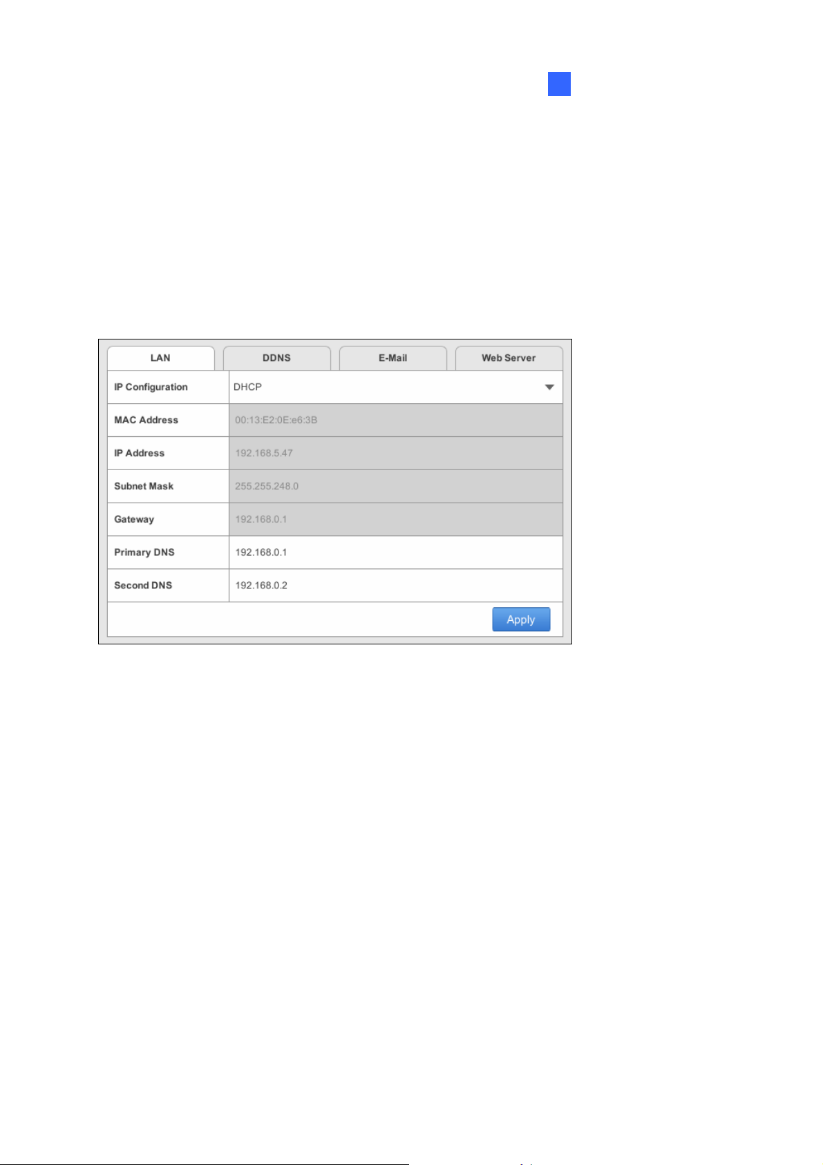
[LAN]
Figure 3-4
IP Configuration: Select DHCP or Static according to your network environment.
MAC Address: Displays the MAC Address of the GV-SNVR.
To assign a static IP address, select Static and fill out the required settings below.
IP Address: Type a static IP address for the GV-SNVR. The default is 192.168.0.100.
Subnet Mask: Type a subnet mask. The default is 255.255.255.0.
Gateway: Type a gateway. The default is 192.168.0.1.
Primary DNS: Type a primary DNS. The default is 192.168.0.1.
Second DNS: Type a second DNS. The default is 192.168.0.2.
Click Apply. The GV-SNVR is now accessible by entering the assigned IP address on Web
browser.
39
Page 45

[WAN]
Figure 3-5
IP Configuration: Select DHCP or Static according to your network environment.
MAC Address: Displays the MAC Address of the GV-SNVR.
To enable the PPPoE connection, select PPPoE and fill out the required settings below.
Primary DNS: Type a primary DNS. The default is 192.168.100.1.
Second DNS: Type a second DNS. The default is 192.168.100.2.
PPPoE Username: Type the username you have registered for PPPoE.
PPPoE Password: Type the password you have registered for PPPoE.
Note: The WAN configuration is only available for GV-SNVR1600.
IMPORTANT: When the LAN and WAN are applied simultaneously, note the following:
y Only the WAN can be connected to the Internet.
y Only the IP Cameras under the same LAN can be searched by the GV-SNVR1600. To
connect with the IP cameras under the WAN, you must add the cameras manually. For
details, see 2.3.2 Manually Connecting GV-IP Camera.
40
Page 46

System Configuration
3
[DDNS]
DDNS (Dynamic Domain Name System) provides a convenient way of accessing the
GV-SNVR when using a dynamic IP address. DDNS assigns a domain name to the
GV-SNVR, so you do not need to go through the trouble of checking if the IP address
assigned by DHCP Server or ISP (in xDSL connection) has changed. Before enabling the
following DDNS function, you should have applied for a Host Name from the DDNS service
provider’s website. The provider is GeoVision DDNS Server:
http://ns.gvdip.com/register.aspx
.
Figure 3-6
To enable the DDNS function, click the Enable box, type the hostname and password you
have registered with GeoVision DDNS Server and click Apply.
41
 Loading...