

Page 1
Quick Start Guide
GV-IP Camera H.264
Before attempting to connect or operate this product,
please read these instructions carefully and save this manual for future use.
ICH264-QG-AL-EN
Page 2

© 2015 GeoVision, Inc. All rights reserved.
Under the copyright laws, this manual may not be copied, in whole or in part,
without the written consent of GeoVision.
Every effort has been made to ensure that the information in this manual is
accurate. GeoVision, Inc. makes no expressed or implied warranty of any
kind and assumes no responsibility for errors or omissions. No liability is
assumed for incidental or consequential damages arising from the use of
the information or products contained herein. Features and specifications
are subject to change without notice. Note that memory card slot (local
storage) is not supported for Argentina.
GeoVision, Inc.
9F, No. 246, Sec. 1, Neihu Rd.,
Neihu District, Taipei, Taiwan
Tel: +886-2-8797-8377
Fax: +886-2-8797-8335
http://www.geovision.com.tw
Trademarks used in this manual: GeoVision, the GeoVision logo and GV
series products are trademarks of GeoVision, Inc. Windows and Windows
XP are registered trademarks of Microsoft Corporation.
September 2015
Page 3

Safety Notice
UL Certification for GV-MFD120 / 130 / 320
The GV-IPCAM H.264 uses a 3.0V CR2032 Lithium battery as the power
supply for its internal real-time clock (RTC). The battery should not be
replaced unless required!
If the battery does need replacing, please observe the following:
Danger of Explosion if battery is incorrectly replaced
Replace only with the same or equivalent battery, as recommended
by the manufacturer
Dispose of used batteries according to the manufacturer's instructions
i
Page 4

Contents
Safety Notice .................................................................................i
Contents .......................................................................................ii
Introduction ............................................................................... viii
Options .....................................................................................xxii
Note for Connecting to GV-System / GV-VMS......................xxiv
Note for Recording...................................................................xxv
Note for GV-BX2600................................................................xxvi
Note for Adjusting Focus and Zoom ....................................xxvii
Note for Installing Camera Outdoor ....................................xxviii
Note for Closing the Bullet Camera Cover.............................xxx
Note for Bullet Camera Waterproof.......................................xxxi
Note for USB Storage and WiFi Adapter..............................xxxii
1. Box Camera ..............................................................................1
1.1 Packing List...............................................................................1
1.2 Overview ...................................................................................2
GV-BX120D / 130D Series / 140DW / 220D Series / 320D
Series / 520D ........................................................................2
GV-BX1200 Series / 1300 Series / 1500 Series / 2400 Series /
2500 Series / 2600 / 3400 Series / 5300 Series / 12201........4
1.3 Accessory Installation................................................................7
1.3.1 C-Mount Lenses...........................................................7
1.3.2 Infrared Illuminators (Optional) .....................................8
1.4 Connecting the Camera.............................................................9
GV-BX120D / 130D Series / 140DW / 220D Series / 320D
Series / 520D ........................................................................9
GV-BX1200 Series / 1300 Series / 1500 Series / 2400 Series /
2500 Series / 2600 / 3400 Series / 5300 Series/ 12201.......11
2. Ultra Box Camera...................................................................13
2.1 Packing List.............................................................................13
2.2 Overview .................................................................................14
ii
Page 5

2.3 Insta
2.4 Connecting the Camera...........................................................17
llation...............................................................................15
3. Target Box Camera ................................................................18
3.1 Packing List.............................................................................18
3.2 Overview .................................................................................19
3.3 Installation ...............................................................................20
3.4 Connecting the Camera...........................................................22
4. IR Arctic Box Camera ............................................................23
4.1 Packing List.............................................................................23
4.2 Overview .................................................................................25
4.3 Installation ...............................................................................27
4.4 Connecting the Camera...........................................................32
5. Mini Fixed Dome & Mini Fixed Rugged Dome .....................36
5.1 Packing List.............................................................................36
5.2 Overview .................................................................................38
GV-MFD120 / 130 / 320......................................................38
GV-MFD1501 Series / 2401 Series / 2501 Series / 3401 Series
/ 5301 Series.......................................................................40
GV-MDR.............................................................................42
5.3 Installation ...............................................................................45
GV-MFD Series...................................................................45
GV-MDR Series ..................................................................47
5.4 Connecting the Camera...........................................................51
5.4.1 Wire Definition............................................................51
5.4.2 Power and Network Connection.................................52
5.4.3 Vehicle Installation .....................................................53
6. Target Mini Fixed Dome.........................................................54
6.1 Packing List.............................................................................54
6.2 Overview .................................................................................55
6.3 Installation ...............................................................................56
6.4 Connecting the Camera...........................................................58
iii
Page 6

7. Target Mini Fixed Rugged Dome ..........................................59
7.1 Packing List.............................................................................59
7.2 Overview .................................................................................61
7.3 Installation ...............................................................................62
7.4 Connecting the Camera...........................................................68
8. Bullet Camera (Part I).............................................................69
8.1 Packing List.............................................................................69
8.2 Overview .................................................................................70
8.3 Installation ...............................................................................71
8.3.1 Adjusting the Angles ..................................................73
8.3.2 Adjusting Lens and Inserting a Memory Card .............76
8.3.3 Inserting the Sun-Shield Cover...................................79
8.4 Connecting the Camera...........................................................80
8.4.1 Wire Definition............................................................80
8.4.2 Connecting the Power Cable......................................82
9. Bullet Camera (Part II)............................................................83
9.1 Packing List.............................................................................83
9.2 Overview .................................................................................84
9.3 Installation ...............................................................................86
9.4 Connecting the Camera...........................................................93
10. Ultra Bullet Camera..............................................................95
10.1 Packing List...........................................................................95
10.2 Overview ...............................................................................96
10.3 Installation .............................................................................98
10.4 Connecting the Camera.......................................................102
10.4.1 Waterproofing the Cable ........................................102
10.4.2 Wire Definition........................................................104
10.4.3 Power Connection..................................................105
11. Target Bullet Camera......................................................... 106
11.1 Packing List.........................................................................106
11.2 Overview .............................................................................107
iv
Page 7

11.3 Instal
11.4 Connecting the Camera.......................................................112
lation ...........................................................................109
11.4.1 Wire Definition........................................................112
11.4.2 Power Connection..................................................113
12. Vandal Proof IP Dome (Part I) ...........................................114
12.1 Packing List.........................................................................114
12.2 Overview .............................................................................116
12.3 Installation...........................................................................118
12.3.1 Hard-Ceiling Mount ................................................119
12.3.2 In-Ceiling Mount .....................................................124
12.4 Connecting the Camera.......................................................127
12.4.1 Wire Definition........................................................127
12.4.2 Connecting the Power Cable..................................129
13. Vandal Proof IP Dome (Part II) ..........................................130
13.1 Packing List.........................................................................130
13.2 Overview .............................................................................133
13.3 Installation...........................................................................135
13.4 Connecting the Camera.......................................................146
13.4.1 Connecting the Power Cable..................................146
13.4.2 Connecting the I/O Device......................................147
14. Target Vandal Proof IP Dome............................................148
14.1 Packing List.........................................................................148
14.2 Overview .............................................................................151
14.3 Installation...........................................................................153
14.4 Connecting the Camera.......................................................162
15. Fixed IP Dome ....................................................................163
15.1 Packing List.........................................................................163
15.1.1 Packing List for Hard-Ceiling Mount .......................163
15.1.2 Packing List for In-Ceiling Mount ............................164
15.2 Overview .............................................................................165
15.3 Installation...........................................................................167
v
Page 8

15.3.1 Hard-Ceiling Mount ................................................167
15.3.2 In-Ceiling Mount .....................................................171
15.3.3 Wall-Surface Mount................................................175
15.4 Connecting the Camera.......................................................177
16. Target Fixed IP Dome ........................................................178
16.1 Packing List.........................................................................178
16.2 Overview .............................................................................179
16.3 Installation...........................................................................181
16.4 Connecting the Camera.......................................................183
17. Cube Camera...................................................................... 184
17.1 Packing List.........................................................................184
17.2 Overview .............................................................................185
17.3 Installation...........................................................................186
17.4 Connecting the Camera.......................................................188
18. Advanced Cube Camera....................................................189
18.1 Packing List.........................................................................189
18.2 Overview .............................................................................190
18.3 Installation...........................................................................192
18.4 Connecting the Camera.......................................................194
19. PT Camera ..........................................................................195
19.1 Packing List.........................................................................195
19.2 Overview .............................................................................197
19.3 Installation...........................................................................199
19.3.1 Ceiling Mount .........................................................199
19.3.2 L-Shaped Wall Mount.............................................201
19.4 Connecting the Camera.......................................................204
20. Pinhole Camera.................................................................. 205
20.1 Packing List.........................................................................205
20.2 Overview .............................................................................207
20.3 Installation...........................................................................209
vi
Page 9

20.4 Connecti
ng the Camera.......................................................213
21. Accessing the Camera.......................................................214
21.1 System Requirement ...........................................................214
21.2 Accessing the Live View......................................................215
21.2.1 Checking the Dynamic IP Address .........................216
21.2.2 Configuring the IP Address.....................................218
21.2.3 Configuring the Wireless Connection......................220
21.3 Adjusting Image Clarity........................................................224
21.3.1 Using Focus Adjustment Cap .................................227
22. The Web Interface ..............................................................228
23. Upgrading System Firmware.............................................231
24. Restoring to Default Settings............................................233
24.1 Using the Web Interface ......................................................233
24.2 Directly on the Camera........................................................234
Box Camera......................................................................234
Ultra Box Camera and Target Box Camera.......................235
Mini Fixed Dome...............................................................236
Mini Fixed Rugged Dome..................................................237
IR Arctic Box Camera........................................................237
Target Mini Fixed Target Mini Fixed Rugged Dome ..........238
Bullet Camera...................................................................239
Ultra Bullet Camera...........................................................240
Target Bullet Camera........................................................240
Vandal Proof IP Dome ......................................................241
Target Vandal Proof IP Dome ...........................................242
Fixed IP Dome..................................................................243
Target Fixed IP Dome.......................................................244
Cube Camera ...................................................................245
Advanced Cube Camera...................................................245
PT Camera .......................................................................246
vii
Page 10

Pinhole Came
ra ................................................................247
viii
Page 11
Introduction
Welcome to the GV-IPCam H.264 Quick Start Guide. In this quick guide,
you will find information on the installation and basic configurations of the
GV-IPCam H.264 series.
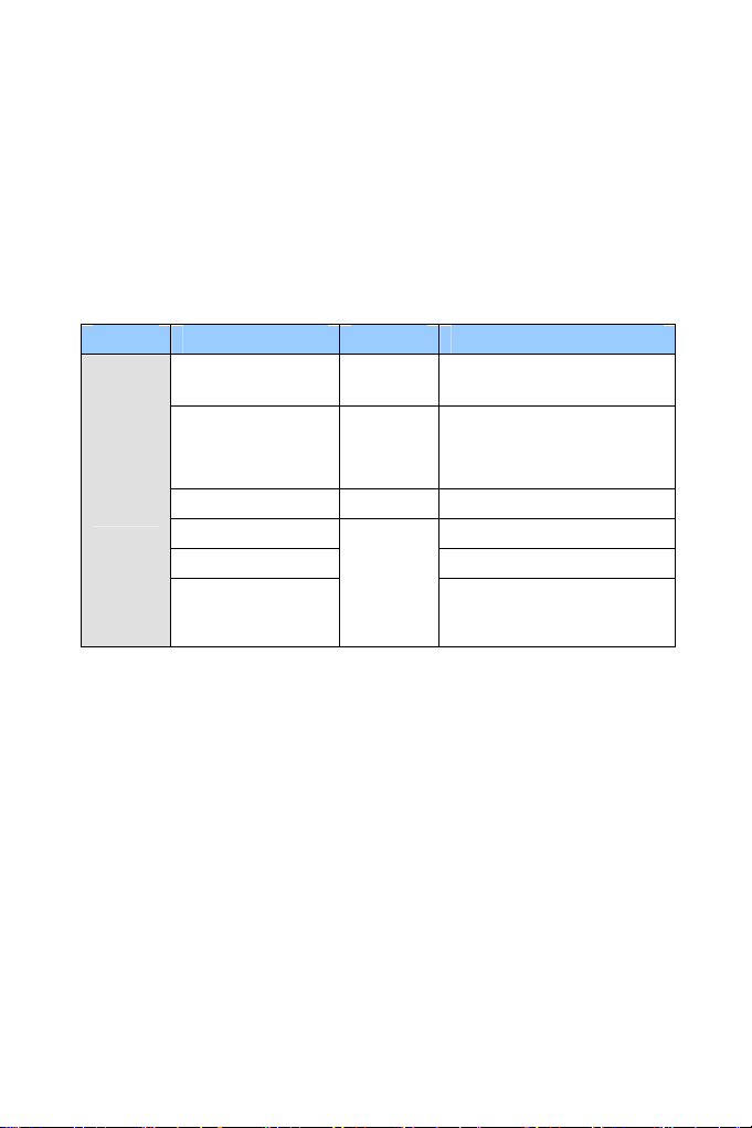
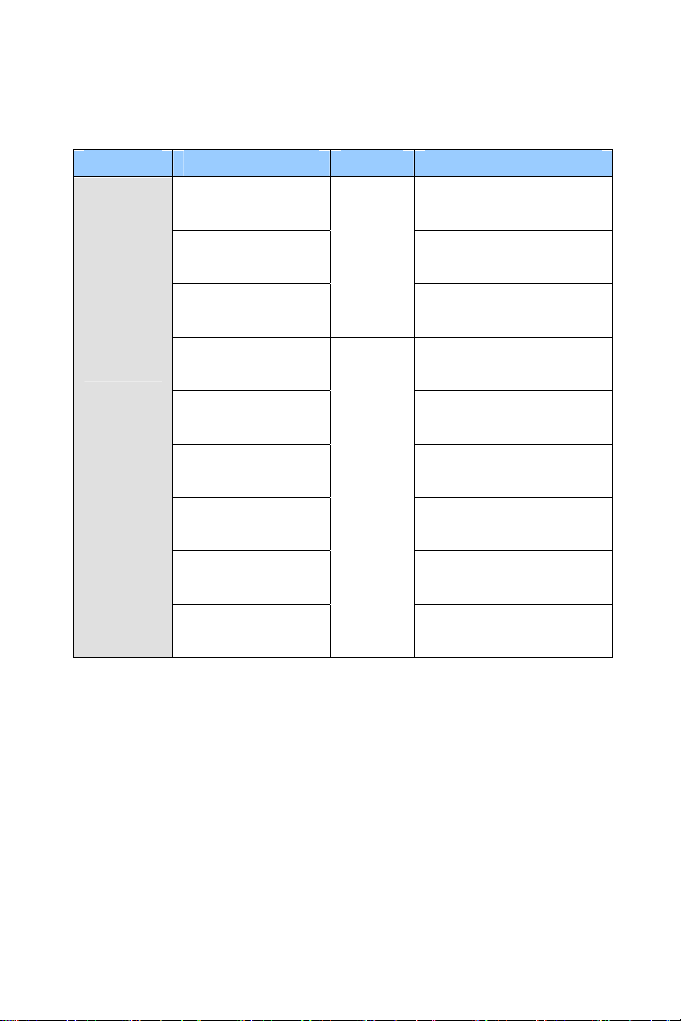
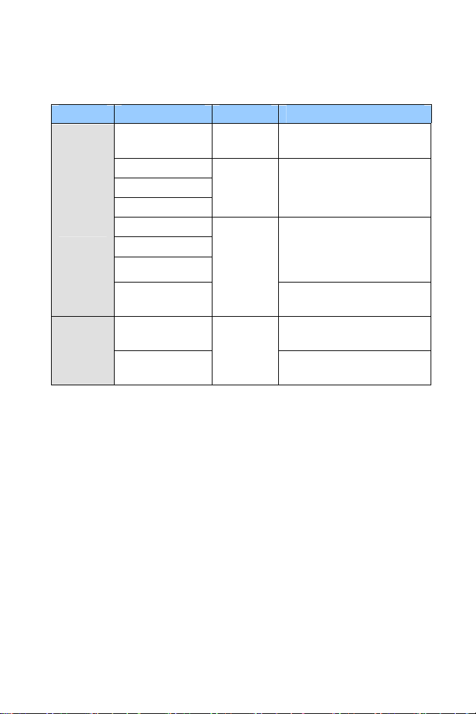
Camera Model No. Lens Description
GV-BX120D Varifocal 1.3 MP, Low Lux, Auto Iris
Box
Camera
GV-BX130D-0
GV-BX130D-1 Fixed 1.3 MP, Fixed Iris
GV-BX140DW 1 MP, WDR Pro, Fixed Iris
GV-BX220D-2 2 MP, Auto Iris
GV-BX220D-3
Varifocal
Varifocal
1.3 MP, Auto Iris
2 MP, Auto Iris
ix
Page 12

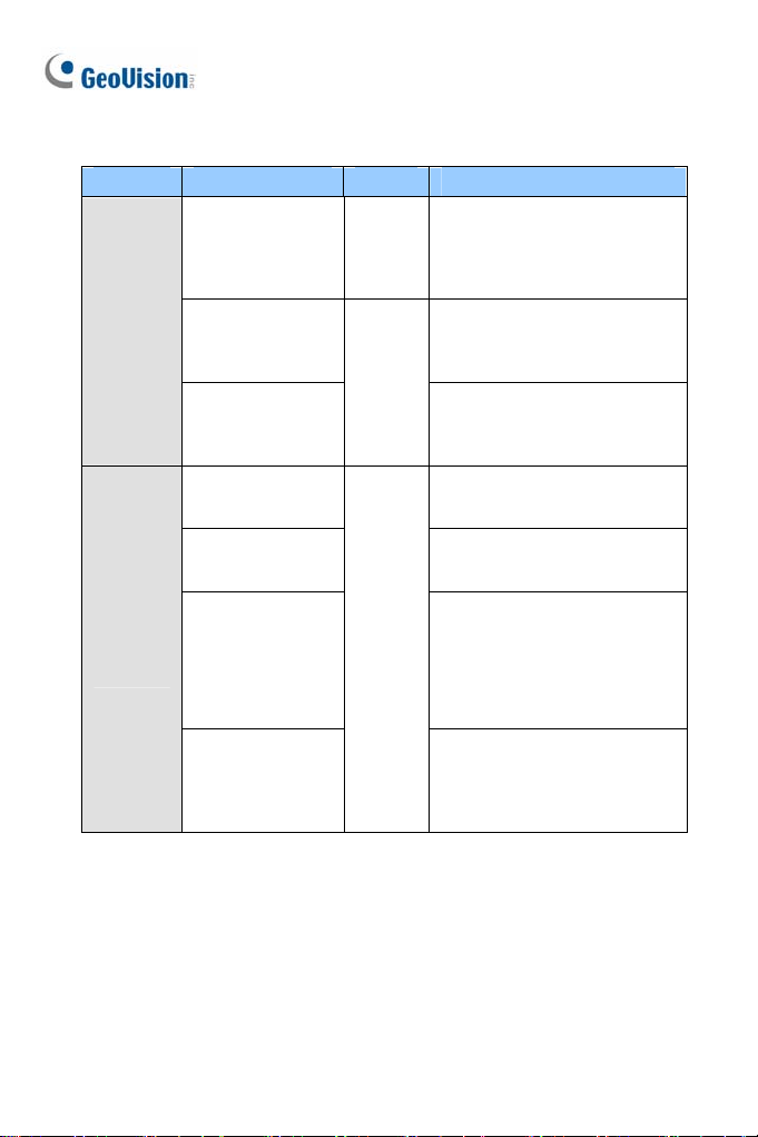
Camera Model No. Lens Description
Box
Camera
GV-BX320D-0
GV-BX320D-1
GV-BX520D
GV-BX1200-0F
GV-BX1300-0F
GV-BX1200-1F
GV-BX1300-1F
GV-BX1500-1F
GV-BX2500-1F
GV-BX1200-2F
GV-BX1300-2F
GV-BX1500-2F
GV-BX2500-2F
Varifocal
Fixed
3 MP, Auto Iris
5 MP, Manual Iris
1.3 MP Low Lux / 1.3 MP,
D/N, Fixed Iris
1.3 MP Low Lux / 1.3 MP /
1.3 MP Super Low Lux / 2
MP WDR Pro / 2 MP Super
Low Lux, Fixed Iris
1.3 MP Low Lux / 1.3 MP /
1.3 MP Super Low Lux / 2
MP Super Low Lux, Fixed
Iris
GV-BX2400-1F
GV-BX3400-1F
x
Varifocal
2 MP / 3 MP, WDR Pro,
Fixed Iris
Page 13
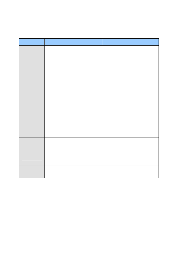
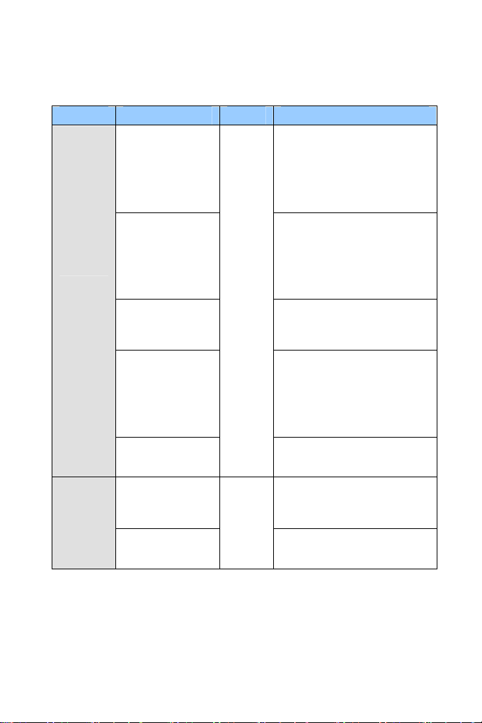
Camera Model No. Lens Description
Box
Camera
Box
Camera
(Coming)
Box
Camera
GV-BX2400-2F
GV-BX3400-2F
GV-BX1200-3V
GV-BX1300-3V
GV-BX1500-3V
GV-BX2500-3V
GV-BX2600
GV-BX3400-5V 3 MP, WDR Pro, Auto Iris
GV-BX5300-6V
GV-BX1500-8F
GV-BX2500-8F
GV-BX3400-8F
GV-BX5300-8F
GV-BX1500-3V
GV-BX2500-3V
GV-BX3400-3V
GV-BX5300-6V
GV-BX12201 Varifocal 12 MP, Auto Iris
Varifocal
Fixed
Varifocal
2 MP / 3 MP, WDR Pro,
Fixed Iris
1.3 MP Low Lux / 1.3 MP /
1.3 MP Super Low Lux / 2
MP Super Low Lux, Auto
Iris
2 MP, Super Low Lux,
WDR Pro, Auto Iris
5 MP, Manual Iris
1.3 MP Super Low Lux / 2
MP Super Low Lux / 3 MP
WDR Pro / 5 MP, Fixed Iris
1.3 MP Low Lux / 2 MP
Super Low Lux / 3 MP
WDR Pro, P-Iris
5 MP, P-Iris
xi
Page 14
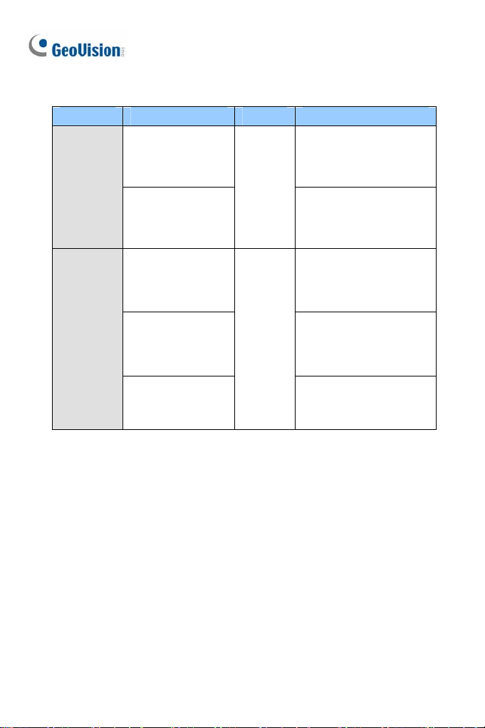
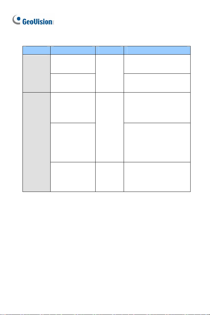
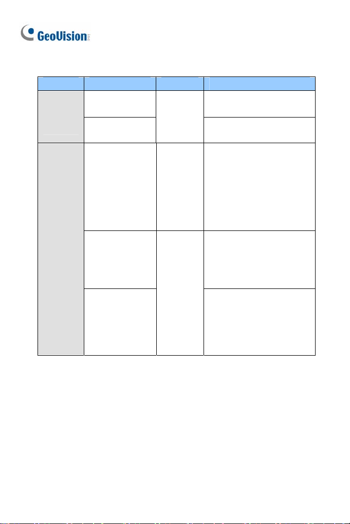
Camera Model No. Lens Description
Target
Box
Camera
Ultra Box
Camera
GV-EBX1100-0F
GV-EBX1100-2F
GV-UBX1301-0F
GV-UBX1301-1F
GV-UBX1301-2F
GV-UBX2301-0F
GV-UBX2301-1F
GV-UBX2301-2F
GV-UBX3301-0F
GV-UBX3301-1F
GV-UBX3301-2F
Fixed
Fixed
1.3 MP, Low Lux, Fixed
Iris
1.3 MP, Low Lux, Fixed
Iris
1.3 MP, Fixed Iris
2 MP, Fixed Iris
3 MP, D/N, Fixed Iris
xii
Page 15
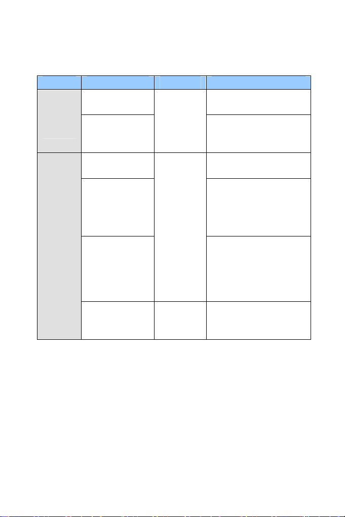
Camera Model No. Lens Description
GV-BX120D-E
GV-BX220D-E 2 MP, Auto Iris
Varifocal
1.3 MP, Low Lux, Auto
Iris
IR Arctic
Box
Camera
GV-BX320D-E
GV-BX520D-E 5 MP, Manual Iris
GV-BX1500-E
GV-BX2400-E
GV-BX3400-E
GV-BX5300-E 5 MP, Manual Iris
GV-BX2510-E
GV-BX5310-E
Varifocal
3 MP, Auto Iris
1.3 MP, Super Low Lux,
Auto Iris
2 MP / 3 MP, WDR Pro,
Auto Iris
2 MP Super Low Lux,
P-Iris
5 MP, P-Iris
xiii
Page 16
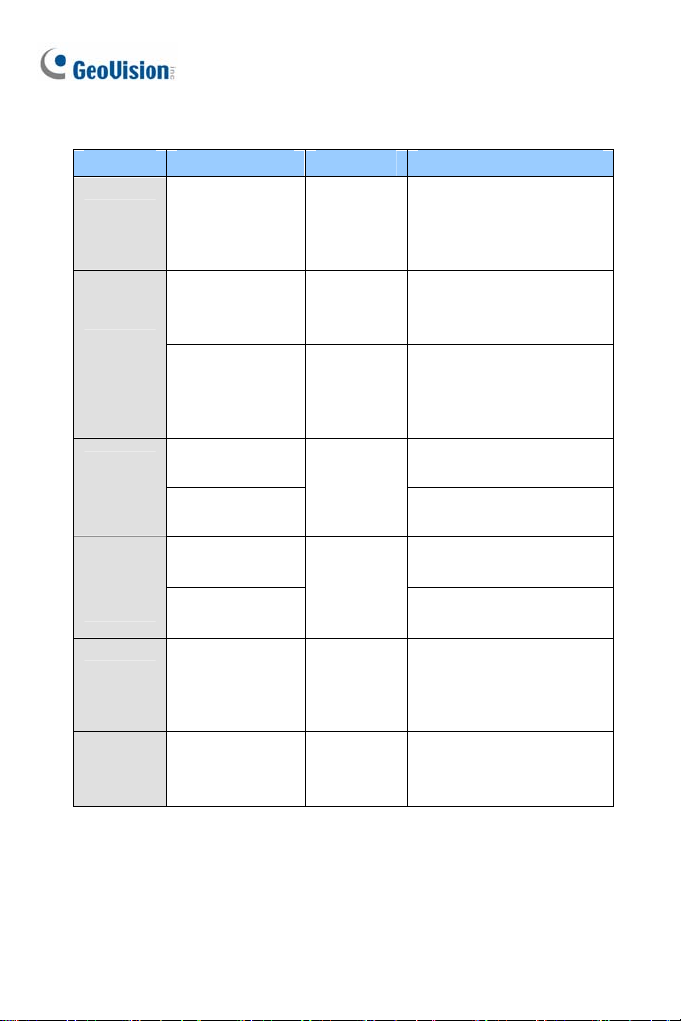
Camera Model No. Lens Description
Mini
Fixed
Rugged
Dome
Mini
Fixed
Dome
GV-MDR220
GV-MDR320
GV-MDR520
GV-MDR1500-1F
GV-MDR3400-1F
GV-MDR5300-1F
GV-MDR1500-2F
GV-MDR3400-2F
GV-MDR5300-2F
GV-MFD120
GV-MFD130
GV-MFD320
GV-MFD1501-0F
GV-MFD2401-0F
GV-MFD2501-0F
GV-MFD3401-0F
GV-MFD5301-0F
GV-MFD1501-1F
GV-MFD2501-1F
Fixed
Fixed
Fixed
2 MP / 3 MP / 5 MP, Color,
Fixed Iris
1.3 MP Super Low Lux / 3 MP
WDR Pro, Color, Fixed Iris
1.3 MP Super Low Lux / 3 MP
WDR Pro / 5 MP, Color,
Fixed Iris
1.3 MP Low Lux, Color, Fixed
Iris
1.3 MP / 3 MP, Color, Fixed
Iris
1.3 MP Super Low Lux / 2 MP
WDR Pro / 2 MP Super Low
Lux / 3 MP WDR Pro / 5 MP,
Color, Fixed Iris
1.3 MP Super Low Lux / 2 MP
WDR Pro / 2 MP Super Low
Lux / 3 MP WDR Pro / 5 MP,
Color, Fixed Iris
xiv
Page 17
Camera Model No. Lens Description
Mini
Fixed
Dome
Target
Mini
Fixed
Dome
GV-MFD1501-2F
GV-MFD2401-2F
GV-MFD2501-2F
GV-MFD3401-2F
GV-MFD5301-2F
GV-MFD1501-3F
GV-MFD2401-3F
GV-MFD2501-3F
GV-MFD3401-3F
GV-MFD5301-3F
GV-MFD1501-4F
GV-MFD2401-4F
GV-MFD1501-5F
GV-MFD2401-5F
GV-MFD2501-5F
GV-MFD3401-5F
GV-MFD5301-5F
GV-MFD2501-6F
GV-MFD3401-6F
GV-EFD1100-0F
GV-EFD2100-0F
GV-EFD1100-2F
GV-EFD2100-2F
Fixed
Fixed
1.3 MP Super Low Lux / 2
MP WDR Pro / 2 MP Super
Low Lux / 3 MP WDR Pro / 5
MP, Color, Fixed Iris
1.3 MP Super Low Lux / 2
MP WDR Pro / 2 MP Super
Low Lux / 3 MP WDR Pro / 5
MP, Color, Fixed Iris
1.3 MP Super Low Lux / 2
MP WDR Pro, Color, Fixed
Iris
1.3 MP Super Low Lux / 2
MP WDR Pro / 5 MP Super
Low Lux, Color, Fixed Iris
2 MP Super Low Lux / 3 MP
WDR Pro, Color, Fixed Iris
1.3 MP / 2 MP, Low Lux,
Fixed Iris
1.3 MP / 2 MP, Low Lux,
Fixed Iris
xv
Page 18
Camera Model No. Lens Description
Target
Mini
Fixed
Rugged
Dome
Bullet
Camera
GV-EDR1100-0F
GV-EDR2100-0F
GV-EDR1100-2F
GV-EDR2100-2F
GV-BL120D
GV-BL130D
GV-BL220D
GV-BL320D
GV-BL1500
GV-BL2400
GV-BL2500
GV-BL3400
1.3 MP Low Lux / 2 MP
Low Lux, Fixed Iris
Fixed
1.3 MP Low Lux / 2 MP
Low Lux, Fixed Iris
1.3 MP Low Lux / 1.3 MP /
2 MP / 3 MP, Auto Iris
Varifocal
1.3 MP Super Low Lux / 2
MP WDR Pro / 2 MP Super
Low Lux / 3 MP WDR Pro,
Auto Iris
xvi
GV-BL1210
GV-BL2410
GV-BL3410
Motorized
Varifocal
1.3 MP Low Lux / 2 MP
WDR Pro / 3 MP WDR Pro,
Auto Iris, 3X Optical Zoom
Page 19
Camera Model No. Lens Description
Bullet
Camera
IR Arctic
Bullet
Camera
GV-BL5310
GV-BL1501
GV-BL2501
GV-BL3401
GV-BL1511
GV-BL2511
GV-BL3411
GV-BL5311
GV-BL2511-E
GV-BL5311-E
Motorized
Varifocal
Varifocal
Motorized
varifocal
Motorized
Varifocal
5 MP, D/N, Auto Iris, 2X
Optical Zoom
1.3 MP Super Low Lux / 2
MP Super Low Lux / 3 MP
WDR Pro, P-Iris
1.3 MP Super Low Lux / 2
MP Super Low Lux / 3 MP
WDR Pro, P-Iris, 3X Optical
Zoom
5 MP, D/N, P-Iris, 2X
Optical Zoom
2 MP Super Low Lux,
P-Iris, 3X Optical Zoom
5 MP, D/N, P-Iris, 2X
Optical Zoom
xvii
Page 20
Camera Model No. Lens Description
Target
Bullet
Camera
GV-EBL1100-1F
GV-EBL2100-1F
GV-EBL1100-2F
GV-EBL2100-2F
Fixed
1.3 MP / 2 MP, Low Lux,
Fixed Iris
1.3 MP Low Lux, Fixed Iris
Ultra
Bullet
Camera
GV-UBL1211
GV-UBL1511
GV-UBL2411
GV-UBL2511
GV-UBL3411
GV-UBL1301-0F
GV-UBL1301-1F
GV-UBL1301-2F
GV-UBL1301-3F
GV-UBL2401-0F
GV-UBL2401-1F
GV-UBL2401-2F
GV-UBL2401-3F
Motorized
Varifocal
Fixed
1.3 MP Low Lux / 1.3 MP
Super Low Lux / 2 MP
WDR Pro / 2 MP Super
Low Lux / 3 MP WDR Pro,
Auto Iris, 3X Optical Zoom
1.3 MP, Fixed Iris
2 MP, WDR Pro, Fixed Iris
xviii
Page 21
Camera Model No. Lens Description
3 MP, Fixed Iris, WDR
Pro
3 MP, Fixed Iris, WDR
Pro
2 MP / 3 MP, Auto Iris
Ultra
Bullet
Camera
GV-UBL3401-0F
GV-UBL3401-1F
GV-UBL3401-2F
GV-UBL3401-3F
GV-FD220D
GV-FD320D
Fixed
Fixed IP
Dome
GV-FD1200
GV-FD2400
GV-FD1500
GV-FD2500
GV-FD3400
GV-FD1210
GV-FD2410
Varifocal
Motorized
Varifocal
1.3 MP Low Lux / 2 MP
WDR Pro, Auto Iris
1.3 MP Super Low Lux / 2
MP Super Low Lux / 3 MP
WDR Pro, Auto Iris
1.3 MP Low Lux / 2 MP
WDR Pro, Auto Iris, 3x
Optical Zoom
xix
Page 22
Camera Model No. Lens Description
1.3 MP Super Low Lux / 2
MP Super Low Lux / 3 MP
WDR Pro, Auto Iris, 3x
Optical Zoom
1.3 MP Super Low Lux / 2
MP Super Low Lux / 3 MP
WDR Pro, P-Iris
1.3 MP Super Low Lux / 2
MP Super Low Lux / 3 MP
WDR Pro, P-Iris, 3x
Optical Zoom
2MP Super Low Lux,
WDR, P-iris
3MP Super Low Lux,
WDR Pro, P-Iris
1.3 MP / 2 MP, Fixed Iris
1.3 MP / 2 MP, Wireless,
Fixed Iris
Fixed IP
Dome
Fixed IP
Dome
Target
Fixed IP
Dome
Advanced
Cube
Camera
GV-FD1510
GV-FD2510
GV-FD3410
GV-FD1500
GV-FD2500
GV-FD3400
GV-FD1510
GV-FD2510
GV-FD3410
GV-EFD2101
GV-EFD3101
GV-CA120
GV-CA220
GV-CAW120
GV-CAW220
Motorized
Varifocal
Varifocal
Motorized
Varifocal
Varifocal
Fixed
Cube
Camera
PT
Camera
xx
GV-CB120
GV-CB220
GV-PT130D
GV-PT220D
GV-PT320D
Fixed 1.3 MP / 2 MP, Fixed Iris
Fixed
1.3 MP / 2 MP / 3 MP,
Fixed Iris
Page 23
Camera Model No. Lens Description
GV-VD120D
(IK10+, Transparent Cover)
GV-VD121D
Vandal
Proof IP
Dome
(IK10+, Smoked Cover)
GV-VD122D
(IK7, Transparent Cover)
GV-VD123D
(IK7, Smoked Cover)
GV-VD220D
(IK10+, Transparent Cover)
GV-VD221D
(IK10+, Smoked Cover)
GV-VD222D
(IK7, Transparent Cover)
GV-VD223D
(IK7, Smoked Cover)
GV-VD320D
(IK10+, Transparent Cover)
GV-VD321D
(IK10+, Smoked Cover)
GV-VD322D
(IK7, Transparent Cover)
GV-VD323D
(IK7, Smoked Cover)
GV-VD1500
(IK10+, Transparent Cover)
GV-VD2400
(IK10+, Transparent Cover)
GV-VD2500
(IK10+, Transparent Cover)
GV-VD3400
(IK10+, Transparent Cover)
Varifocal
1.3 MP, Low Lux,
Auto Iris
2 MP, Auto Iris
3 MP, Auto Iris
1.3 MP Super Low
Lux / 2 MP WDR
Pro / 2 MP Super
Low Lux / 3 MP
WDR Pro, Auto Iris
xxi
Page 24
Camera Model No. Lens Description
Vandal
Proof IP
Dome
GV-VD1530
GV-VD2430
GV-VD2530
GV-VD3430
GV-VD1540
GV-VD2440
GV-VD2540
GV-VD3440
GV-VD5340
High Power IR
LEDs,
Varifocal
High Power IR
LEDs,
Motorized
Varifocal
1.3 MP Super Low Lux / 2
MP WDR Pro / 2 MP
Super Low Lux / 3 MP
WDR Pro, Auto Iris
1.3 MP Super Low Lux / 2
MP WDR Pro / 2 MP
Super Low Lux / 3 MP
WDR Pro, Auto Iris, 3X
Optical Zoom
5 MP, Auto Iris, 3X Optical
Zoom
High Power IR
GV-VD2540-E
GV-VD5340-E
Target
Vandal
Proof IP
Dome
Pinhole
Camera
For detailed manuals, see GV-IPCAM H.264 Firmware Manual and
GV-IPCAM H.264 Hardware Manual on the Software DVD.
xxii
GV-EVD2100
GV-EVD3100
GV-UNP2500 Fixed
LEDs,
Motorized
Varifocal
Lens, Extreme
Temperature
Tolerance
Varifocal
2 MP Super Low Lux,
Auto Iris, 3X Optical Zoom
5 MP, Auto Iris, 3X Optical
Zoom
2MP Super Low Lux,
WDR, P-Iris
3MP Super Low Lux,
WDR Pro, P-Iris
2 MP Super Low Lux,
Fixed Iris
Page 25

Options
Optional devices can expand your camera’s capabilities and versatility.
Contact your dealer for more information.
Accessory Description
The power adapter is available for all GV-IP Camera
(except for IR Arctic Cameras, Mini Fixed Rugged
Power Adapter
GV-PA191 PoE
Adapter
GV-PA481 PoE
Adapter
GV-PA482 PoE
Adapter
GV-POE Switch
GV-Mount
Accessories
Dome and GV-BL2510-E / 5310-E). Contact your
sales representative for the countries and areas
supported.
The GV-PA191 PoE adapter is designed to provide
power and network connection to the cameras over a
single Ethernet cable.
The GV-PA481 PoE adapter is designed to provide
power and network connection to GV-BX1200-E /
2400-E / 3400-E / 5300-E over a single Ethernet
cable.
The GV-PA482 PoE adapter is designed to provide
power and network connection to GV-BX2510-E /
5310-E over a single Ethernet cable.
The GV-POE Switch is designed to provide power
along with network connection for IP devices. The
GV-POE Switch is available in various models with
different numbers and types of ports.
The GV-Mount Accessories provide a
comprehensive lineup of accessories for installation
on ceiling, wall corner and pole. For details, see
GV-Mount Accessories Installation Guide on the
Software DVD.
xxiii
Page 26
Accessory Description
The GV-WiFi Adapter is a plug-and-play device
designed to connect GV-BX1200 Series / 1300
series / 1500 series / 2400 series / 2500 series /
GV-WiFi Adapter
GV-Relay V2
Smoked Cover
Plastic PG21
Conduit
Connector
Metal PG21
Conduit
Connector
3400 series / 5300 series and GV-MFD1501 series /
2401 series / 2501 series / 3401 series / 5301 series
to wireless network. This product complies with IEEE
802.11 b/g/n (Draft 3.0) standards for wireless
networking.
The GV-Relay V2 is designed to expand the voltage
load of GV IP devices. It provides 4 relay outputs,
and each can be set as normally open (NO) or
normally closed (NC) independently as per your
requirement.
The smoked cover is an IK7, tinted camera cover
designed for GV-Fixed IP Dome to conceal the
direction of the camera lens.
The plastic PG21 conduit connector is used for
running the wires of Target Mini Fixed Rugged Dome
through a 1/2” conduit pipe.
The metal PG21 conduit connector is used for
running the wires of GV-VD1530 / 2430 / 2530 /
3430, GV-VD1540 / 2440 / 2540 / 3440 / 5340 and
GV-VD2540-E / 5340-E through a 3/4” conduit pipe.
xxiv
Page 27

Note for Connecting to GV-System / GV-VMS
The GV-IPCAM H.264 is designed to work with GV-System / GV-VMS, a
hybrid or digital video management system. Note the following when
GV-IPCAM H.264 is connected to GV-System / GV-VMS:
1. By default, the images are recorded to the memory card inserted to the
GV-IP Camera H.264 (except GV-IR Arctic Camera and Target Series,
which are not equipped with a memory card slot).
2. Once the camera is connected to GV-System / GV-VMS, the
resolution set on GV-System / GV-VMS will override the resolution set
on the camera’s Web interface. You can only change the resolution
settings through the Web interface when the connection to GV-System
/ GV-VMS is interrupted.
xxv
Page 28

Note for Recording
1. By default, the images are recorded to the memory card inserted to the
GV-IP Camera H.264 (except GV-IR Arctic Camera and Target Series,
which are not equipped with a memory card slot). Make sure the Write
recording data into local storage option is enabled. If this option is
disabled, the camera will stop recording to the memory card while the
live view is accessed through Web browsers or other applications. For
details, see Video Settings, Administrator Chapter, GV-IPCAM H.264
Firmware Manual on the Software DVD).
2. Mind the following when using a memory card for recording:
Recorded data on the memory card can be damaged or lost if the
data are accessed while the camera is under physical shock,
power interruption, memory card detachment or when the memory
card reaches the end of its lifespan. No guarantee is provided for
such causes.
The stored data can be lost if the memory card is not accessed for
a long period of time. Back up your data periodically if you seldom
access the memory card.
Memory cards are expendable and their durability varies according
to the conditions of the installed site and how they are used. Back
up your data regularly and replace the memory card annually.
Replace the memory card when its read/write speed is lower than
6 MB/s or when the memory card is frequently undetected by the
camera.
3. It is recommended to use memory cards of the following setting and
specifications:
Apply a battery backup (UPS) to avoid power outage.
Use Micro SD card of MLC NAND flash, Class 10 for better
performance.
xxvi
Page 29

Note for GV-BX2600
Frame Rate
Mind the following restrictions, without regard to the resolution of the
camera images, when the GV-BX2600 camera is set to 60 frames per
second (fps):
1 The codec MJPEG is not available in the main stream.
2 Dual streaming is not supported.
3 Video analysis functions, including motion detection, are not
supported.
4 TV-out is not supported.
5 The frame rate will be dropped to 30 fps during live streaming and
recording when the camera starts monitoring.
6 WDR Pro function is not supported.
7 1 or 2 fps will be dropped on the point of obtaining snapshots in JPEG
format with the CGI command.
Browser
For the users of Microsoft Internet Explorer, version 11 or later is required to
perform the GV-IPCAM H.264 operations through Web browser.
Recording
When GV-BX2600 uses Micro SD card or USB HDD for recording, the
camera must not have more than one connection to GeoVision or
third-party software.
xxvii
Page 30
Note for Adjusting Focus and Zoom
When adjusting the Focus and Zoom Screws (on Box Camera, IR Arctic
Box Camera, Mini Fixed Dome, Bullet Camera, Vandal Proof IP Dome and
Fixed IP Dome), please do not over tighten the Focus and Zoom screws.
The screws only need to be as tight as your finger can do it; don't bother
using any tools to get them tighter. Doing so can damage the structure of
lens.
For example,
Zoom Screw
Focus Screw
Bullet Camera Fixed IP Dome
The maximum torque value for all the zoom and focus screws is 0.049 N.m
Focus Screw
Zoom Screw
xxviii
Page 31

Note for Installing Camera Outdoor
When installing the IR Arctic Box Camera, Bullet Camera, Ultra Bullet
Camera, Target Bullet Camera, Vandal Proof IP Dome, Mini Fixed
Rugged Dome or Target Mini Fixed Rugged Dome outdoor, be sure that:
1. The camera is set up above the junction box to prevent water from
entering the camera along the cables.
2. Any PoE, power, audio and I/O cables are waterproofed using
waterproof silicon rubber or the like.
xxix
Page 32

ter opening the camera cover, ensure the screws are tightened and
3. Af
the cover is in place.
4. The silica gel bag loses it effectiveness when the dry camera is
opened. To prevent the lens from fogging up, replace the silica gel bag
every time you open the camera, and conceal the gel bag in camera
within 2 minutes of exposing to open air.
xxx
Page 33

Note for Closing the Bullet Camera Cover
To ensure that the camera performs its full capacity against water and dust,
tightly close and lock the camera cover as indicated below.
xxxi
Page 34

Note for Bullet Camera Waterproof
To avoid waterproofing failures, do not open the screw on the camera body.
1. The screw on Ultra Bullet Camera
The screw
2.
on Target Bullet Camera
xxxii
Page 35

Note for USB Storage and WiFi Adapter
Mind the following limitations and requirements for using USB storage and
GV-WiFi Adapter:
1. The USB hard drive must be of 2.5’’ or 3.5’’, version 2.0 or above.
2. The USB hard drive’s storage capacity must not exceed 2TB.
3. USB flash drives and USB hubs are not supported.
4. External power supply is required for the USB hard drive.
5. To connect a GV-WiFi Adapter, make sure it is connected before the
camera is powered on.
xxxiii
Page 36

1. Box Camera
1.1 Packing List
Box Camera
Terminal Block
Fixed Focal or Varifocal Megapixel Lens
Six Lens Rings
One Lens Ring (for GV-BX140DW only)
Video Out Wire
Camera Holder
Power Adapter
GV-IPCAM H.264 Software DVD
GV-NVR Software DVD
Warranty Card
Note: The power adapter can be excluded upon request.
1
Box Camera
1
Page 37

1.2 Overview
GV-BX120D / 130D Series / 140DW / 220D Series / 320D Series / 520D
1
2 3 4 5 6
11
12
13
14
15
7 8 9
Note:
1. The Auto Iris Connector (No. 7) is only functional in GV-BX120D,
GV-BX130D-0, GV-BX220D and GV-BX320D.
2. The Light Sensor (No. 11) is only available in GV-BX140DW. Keep
the Light sensor unobscured for accurate light detection.
3. The Iris Screw (No. 13) is only available for GV-BX520D.
4. The Zoom Screw (No. 15) is not available for GV-BX130D-1.
10
No. Name Description
Connects to a portable monitor for setting
1 Video Out
2 Memory Card Slot
3 Audio Out Connects a speaker for audio output.
4 Audio In Connects a microphone for audio input.
2
the focus and angle of Box Camera during
initial installation.
Receives a micro SD card (SD/SDHC,
version 2.0, Class 10) to store recording
data.
16
Page 38

1
No. Name Description
Connects I/O devices. For details, see I/O
5 I/O Terminal Block
6 Power LED
Auto Iris
7
Connector
8 DC 12V Port Connects to power.
9 LAN / PoE Connects to a 10/100 Ethernet or PoE.
10 Default
11 Light Sensor
12 Focus Screw Adjusts the focus of the camera.
13 Iris Screw Adjusts the iris of the camera
14 Microphone Records the sounds.
15 Zoom Screw Adjusts the zoom of the camera
16 Status LED
LED Description
Power LED turns green
Status LED turns green The system is ready for use.
Terminal Block, Box Camera Chapter,
GV-IPCAM H.264 Hardware Manual on the
Software DVD.
Indicates the power is supplied. For detail,
see the table below.
Plug the iris control cable to the connector.
Resets all configurations to factory default.
See 24. Restoring to Default Settings later in
the Quick Start Guide.
Detects light to switch between day and
night mode.
Turns on when the unit is ready for use. For
detail, see the table below.
The system powers on and succeeds to boot
up.
Box Camera
3
Page 39

GV-BX1200 Series / 1300 Series / 1500 Series / 2400 Series / 2500 Series / 2600 / 3400 Series / 5300 Series / 12201
5
1 2 4
6 7
8 9
GV-BX1200 Series / 1300 Series /
1500 Series / 2400 Series / 2500
Series / 2600 / 3400 Series / 5300
Series
4
10311
GV-BX12201
Page 40

1
Box Camera
Note:
1. The Auto Iris Connector (No. 8) is only functional for varifocal models
of GV-BX1200 / 1300 / 1500 / 2400 / 2500 / 2600 / 3400.
2. The Iris Screw (No. 12) is only available for GV-BX5300-6V.
3. The Zoom Screw (No. 13) is only available for varifocal models of
GV-BX1200 / 1300 / 1500 / 2400 / 2500 / 2600 / 3400 / 5300 / 12201
4. Built-in microphone is not available for GV-BX2600.
5. The Memory Card Slot (No. 2) is currently not supported for
GV-BX12201.
6. Mini USB Slot (No. 3) connected to USB hard drive is currently not
supported for GV-BX12201.
No. Name Description
Connects to a portable monitor for setting the
1 Video Out
Memory Card
2
Slot
3 Mini USB Slot
4 Audio Out Connects a speaker for audio output.
5 Audio In Connects a microphone for audio input.
I/O Terminal
6
Block
7 Power LED
Auto Iris
8
Connector
focus and angle of Box Camera during initial
installation.
Receives a micro SD card (SD/SDHC, version
2.0 only, Class 10) to store recording data.
Connects to a GV-WiFi Adapter or a USB hard
drive.
Connects I/O devices. For details, see I/O
Terminal Block, Box Camera Chapter,
GV-IPCAM H.264 Hardware Manual on the
Software DVD.
Indicates the power is supplied. For detail, see
the table below.
Plug the iris control cable to the connector.
5
Page 41

No. Name Description
9 DC 12V Port Connects to power.
10 LAN / PoE Connects to a 10/100 Ethernet or PoE.
Resets all configurations of the GV-IPCAM
11 Default
12 Iris Screw Adjusts the iris of the camera.
13 Zoom Screw Adjusts the zoom of the camera.
14 Microphone Records the sounds.
15 Focus Screw Adjusts the focus of the camera.
16 Status LED
LED Description
Power LED turns green The system powers on and succeeds to boot up.
Status LED turns green The system is ready for use.
H.264 to the default factory settings. See 24.
Restoring to Default Settings later in the Quick
Start Guide.
Turns on when the unit is ready for use. For
detail, see the table below.
6
Page 42

1
Box Camera
1.3 Accessory Installation
1.3.1 C-Mount Lenses
When you use a C-mount lens, it requires a certain distance from the
camera’s imaging chip to focus the lens. Mount the supplied C-mount lens
adapter / lens ring to the camera, and then attach the lens onto the camera
body.
Box Camera
Three types of lens rings are provided for Box Camera:
0.188 mm (transparent color) x 2
0.125 mm (black color with a glossy surface) x 2
0.254 mm (black color with a matt surface) x 2
For GV-BX140DW, a 0.125 mm lens ring is provided.
Note: These lens rings are specially designed for varifocal models of
Box Camera. Besides the supplied lens rings, each varifocal model has
already been installed with the necessary lens ring.
7
Page 43

1.3.2 Infrared Illuminators (Optional)
1. Connect the infrared illuminator to the terminal block on the camera.
See I/O Terminal Block, Box Camera Chapter, GV-IPCAM H.264
Hardware Manual on the Software DVD.
2. Access the Web interface of the camera.
3. Select Video and Motion, select Video Settings, select Streaming 1
and set the IR Check Function setting to Trigger by Input.
4. Click Apply.
For details on the Trigger by Input function, see the Video Settings section,
Administrator Mode Chapter in the GV-IPCAM H.264 Firmware Manual in
the Software DVD.
8
Page 44

1
Box Camera
1.4 Connecting the Camera
The Box Camera is designed for indoor use. Please make sure the
installing site is shielded from rain and moisture.
GV-BX120D / 130D Series / 140DW / 220D Series / 320D Series / 520D
1. If you are using an auto iris model, plug the iris control cable to the
Auto Iris Connector on the camera.
2. Use a standard network cable to connect the camera to your network.
3. Optionally connect a speaker and an external microphone.
4. Optionally connect a monitor using a Video Out wire. Enable this
function by selecting the signal format at the TV Out field on the Web
interface. See TV Out setting, in the Video Settings section,
Administrator Mode Chapter, GV-IPCAM H.264 Firmware Manual on
the Software DVD.
9
Page 45

5. Opti
6. Connect power using one of the following methods:
onally connect to input / output devices or an infrared illuminator.
For details, see Infrared Illuminator and I/O Terminal Block, Box
Camera Chapter, GV-IPCAM H.264 Hardware Manual on the
Software DVD.
Plug the power adapter to the power port.
Use the Power over Ethernet (PoE) function and the power will be
provided over the network cable.
7. The status LED of the camera will be on.
8. You are ready to access the live view and adjust the image clarity. See
21. Accessing the Camera in the Quick Start Guide.
10
Page 46

1
Box Camera
GV-BX1200 Series / 1300 Series / 1500 Series / 2400 Series / 2500 Series / 2600 / 3400 Series / 5300 Series/ 12201
1. If you are using an auto iris model, plug the iris control cable to the
Auto Iris Connector on the camera.
2. Connect to network using one of the following methods:
Wired Connection: Use a standard network cable to connect the
camera to your network and optionally connect a USB hard drive to
the mini USB port.
Wireless Connection: Optionally purchase and connect the
GV-WiFi Adapter.
3. Optionally connect a speaker and an external microphone.
11
Page 47

4. Optionally connect a monitor using a Video Out wire. Enable this
function by selecting your signal format at the TV Out field on the Web
interface. See TV Out setting, in the Video Settings section,
Administrator Mode Chapter, GV-IPCAM H.264 Firmware Manual on
the Software DVD.
5. Optionally connect to input / output devices or an infrared illuminator.
For details, see Infrared Illuminator and I/O Terminal Block, Box
Camera Chapter, GV-IPCAM H.264 Firmware Manual on the Software
DVD.
6. Connect power using one of the following methods:
Plug the power adapter to the power port.
Use the Power over Ethernet (PoE) function and the power will be
provided over the network cable.
7. The status LED of the camera will be on.
8. You are ready to access the live view and adjust the image clarity. See
21. Accessing the Camera in the Quick Start Guide.
Note: For details on limitations and requirements of the mini USB port,
refer to Note for USB Storage and WiFi Adapter at the beginning of this
quick guide.
12
Page 48

2. Ultra Box Camera
2.1 Packing List
Ultra Box Camera
Supporting rack
Screw x 3
Screw anchor x 3
Power Adapter
GV-IPCAM H.264 Software DVD
GV-NVR Software DVD
Warranty Card
Note: The power adapter can be excluded upon request.
Ultra Box Camera
2
13
Page 49
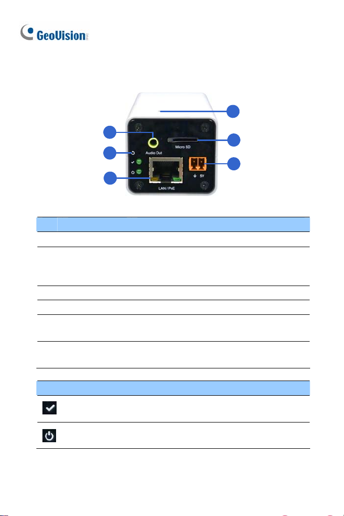
2.2 Overview
4
1
5
2
6
3
No. Name Description
1 Audio Out Connects a speaker for audio output.
Resets the camera to factory defaults. See 24
2 Default
3 LAN / PoE Connects to a 10/100 Ethernet or PoE.
4 Microphone Records sounds.
Memory Card
5
Slot
DC 5V Terminal
6
Block
Restoring to Factory Default Settings in the
Quick Start Guide.
Receives a micro SD card (SD/SDHC, version
2.0 only, Class 10) to store recording data.
Connects to power.
LED Indicator Description
Status LED
Power LED
The status LED turns on (green) when the
system is ready for use.
The power LED turns on (green) when power
is supplied to the camera.
14
Page 50

Ultra Box Camera
2
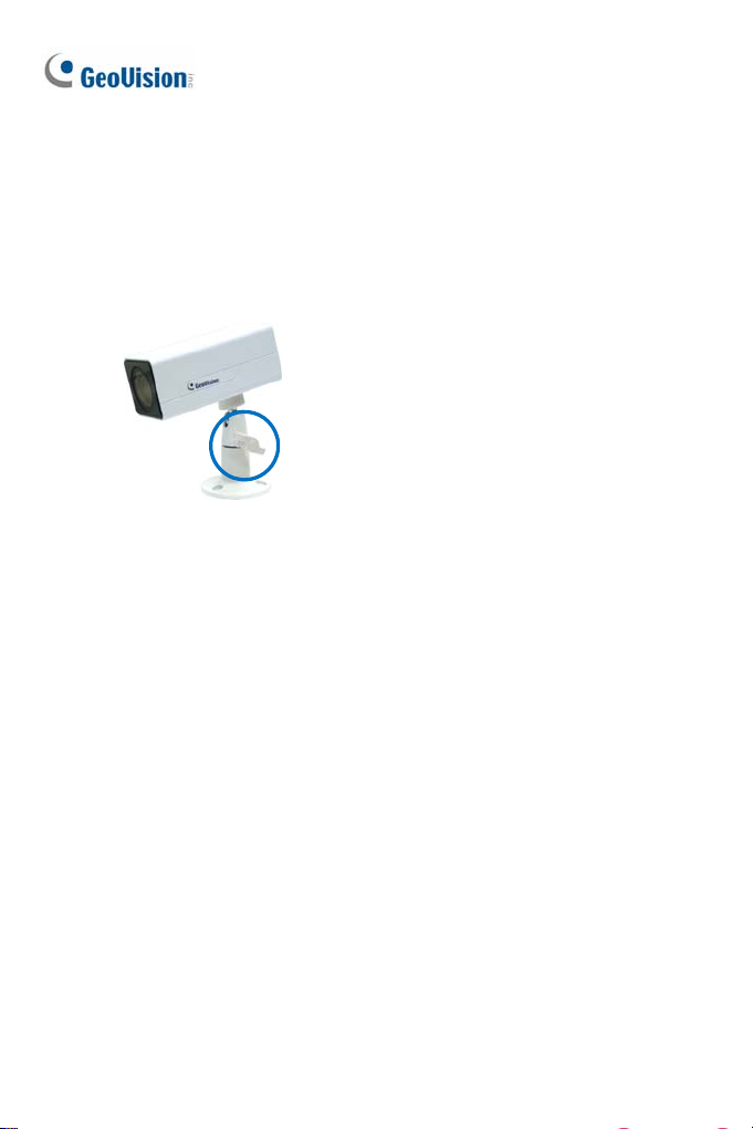
2.3 Installation
You can stand the Ultra Box Camera on a plain surface or install it to wall
and ceiling. Follow the steps below to install, connect and adjust your Ultra
Box Camera.
1. To install the device on the wall/ceiling, put the supporting rack on the
desired location and make marks for screw anchors.
2. Drill the marks and insert the screw anchors.
3. Secure the supporting rack onto the wall/ceiling using the supplied
screws.
4. Secure the camera onto the supporting rack and fasten the indicated
screw.
15
Page 51
t
5. Connec
6. Access the live view. See 21.2 Accessing the Live View in the Quick
7. Adjust the angle of the camera based on live view and fasten the
the network and power cables to the camera. See 2.4
Connecting the Camera in the Quick Start Guide.
Start Guide.
indicated screw.
16
Page 52

2.4 Connecting the Camera
Ultra Box Camera
2
3
1
2
1. Connect power using one of the following methods:
Plug the power adapter to the 5V terminal block.
Use the Power over Ethernet (PoE) function and the power will be
provided over the network cable.
The power and status LEDs shall turn on (green).
2. Use a standard network cable to connect the camera to your network.
3. Optionally connect a speaker.
4. Insert a micro SD card (SD/SDHC, version 2.0 only, Class 10).
5. You are ready to access the live view, adjust the image clarity and
configure the basics. See 21. Accessing the Camera in the Quick Start
Guide.
17
Page 53
3. Target Box Camera
3.1 Packing List
Target Box Camera
Supporting Rack
Screw x 3
Screw Anchor x 3
GV-IPCAM H.264 Software DVD
GV-NVR Software DVD
Warranty Card
Note: Power adapter can be purchased upon request.
18
Page 54
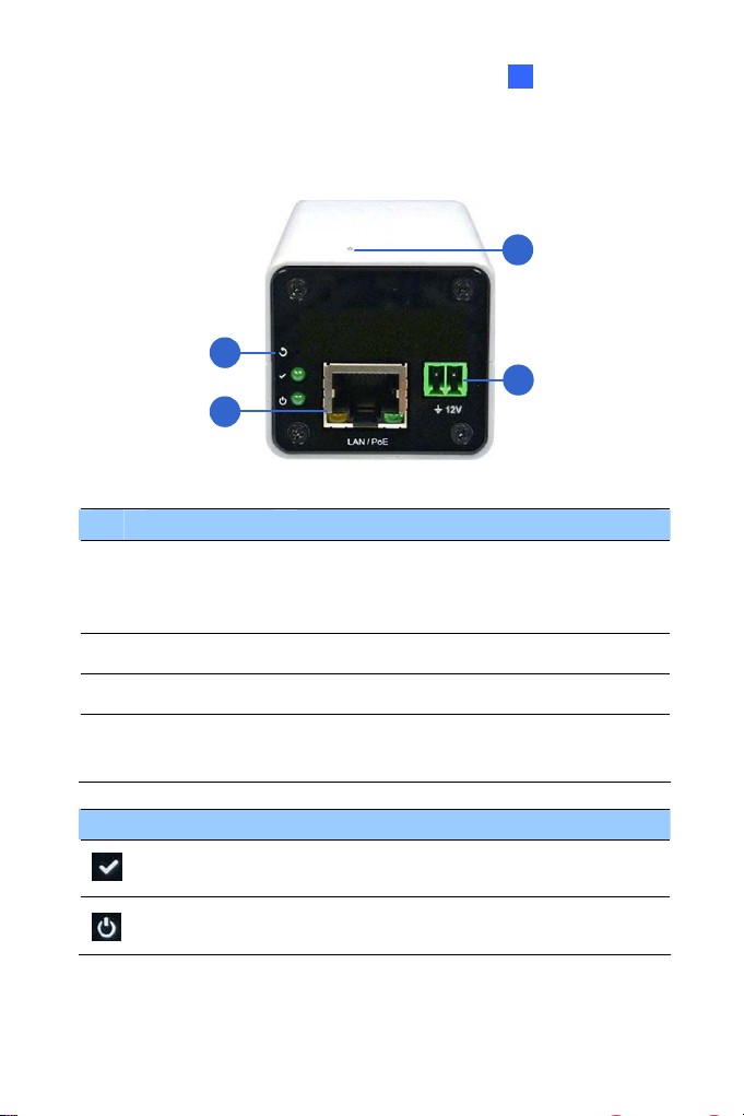
3.2 Overview
1
2
Target Box Camera
3
3
4
No. Name Description
Resets the camera to factory defaults. See 24
1 Default
2 LAN / PoE Connects to a 10/100 Ethernet or PoE.
3 Microphone Records sounds.
DC 12V
4
Terminal Block
Restoring to Factory Default Settings in the
Quick Start Guide.
Connects to power.
LED Indicator Description
Status LED
Power LED
The status LED turns on (green) when the
system is ready for use.
The power LED turns on (green) when power
is supplied to the camera.
19
Page 55
3.3 Installation
You can stand the Target Box Camera on a plain surface or install it to wall
and ceiling. Follow the steps below to install, connect and adjust your
Target Box Camera.
1. To install the device on the wall/ceiling, put the supporting rack on the
desired location and make marks for screw anchors.
2. Drill the marks and insert the screw anchors.
3. Secure the supporting rack onto the wall/ceiling using the supplied
screws.
4. Secure the camera onto the supporting rack and fasten the indicated
screw.
20
Page 56

Target Box Camera
3
5. Connec
6. Access the live view. See 21.2 Accessing the Live View in the Quick
7. Adjust the angle of the camera based on live view and fasten the
the network and power cables to the camera. See 3.4
t
Connecting the Camera in the Quick Start Guide.
Start Guide.
indicated screw.
21
Page 57

3.4 Connecting the Camera
1. Connect power using one of the following methods:
Plug the power adapter to the 12V terminal block. The power
adapter is an optional device. For detail, see Options in the
GV-IPCAM H.264 Hardware Manual for Target Box Camera on the
Software DVD.
Use the Power over Ethernet (PoE) function and the power will be
provided over the network cable. The power and status LEDs shall
turn on (green).
2. Use a standard network cable to connect the camera to your network.
3. You are ready to access the live view, adjust the image clarity and
configure the basics. See 21. Accessing the Camera in the Quick Start
Guide.
22
Page 58

4. IR Arctic Box Camera
4.1 Packing List
For GV-BX120D-E / 220D-E / 320D-E / 520D-E / 1500-E / 2400-E /
3400-E / 5300-E
IR Arctic Box Camera
Screw Anchor x 4
Screw x 4
Washer x 4
4 mm Torx Wrench
5 mm Torx Wrench
Silica Gel Bag x 2
Adhesive Tape x 2
GV-IPCAM H.264 Software DVD
GV-NVR Software DVD
Warranty Card
Note: Optionally purchase a GV-PA481 PoE Adapter for GV-BX1500-E
/ 2400-E / 3400-E / 5300-E.
4
IR Arctic Box Camera
23
Page 59

For GV-BX2510-E
IR Arctic Box Camera
Screw Anchor x 4
Screw x 4
Washer x 4
5 mm Torx Wrench
Silica Gel Bag
Adhesive Tape
Power Adapter (DC 48V, 2.5A, 120 W max.)
GV-IPCAM H.264 Software DVD
GV-NVR Software DVD
Warranty Card
Note: Optionally purchase a GV-PA482 PoE Adapter for GV-BX2510-E
/ 5310-E.
/ 5310-E
24
Page 60

4
IR Arctic Box Camera
4.2 Overview
For GV-BX120D-E / 220D-E / 320D-E / 520D-E / 1500-E / 2400-E /
3400-E / 5300-E
1 2
4
3
5
Note: The Iris Screw (no. 7) is only available in GV-BX520D-E / 5300-E.
No. Name Description
1 Silica gel bag Desiccant that keeps the camera housing dry.
2 IR power plug Supplies power to the built-in IR LEDs.
3 Focus Screw Adjusts the focus of the camera.
4 Module screw Holds the module in place.
5 Status LED Turns on when the camera is ready for use.
6 Zoom Screw Adjusts the zoom of the camera.
7 Iris Screw Adjusts the iris of the camera.
7 6
25
Page 61
For GV-BX2510-E
No. Name Description
1. Silica gel bag Desiccant that keeps the camera housing dry.
Memory Card
2.
Slot
3. Power LED
4. Status LED Turns on when the camera is ready for use.
5. Default
/ 5310-E
1
Inserts a micro SD card (SD/SDHC, version
2.0, Class 10) to store recording data.
Turns on when the camera is supplied with
power.
Resets all configurations to factory default.
See 24. Restoring to Default Settings later in
the Quick Start Guide.
2
3
4
5
26
Page 62

4
IR Arctic Box Camera
4.3 Installation
The IR Arctic Box Camera is designed for outdoor use. Follow the steps
below to install your camera.
IMPORTANT: The gel bag loses its effectiveness when the dry camera
is opened. To prevent the lens from fogging up, you must replace the
silica gel bag every time you open the camera and conceal the silica gel
bag in the camera within 2 minutes of exposing to open air.
1. Mark the installation site and drill four holes for screw anchors.
2. Insert the supplied screw anchors.
3. Secure the camera to the wall using the supplied washers and screws.
4. Connect the camera with wires and cables. See 4.4 Connecting the
Camera in the Quick Start Guide.
5. Access the live view. See 21.2 Accessing the Live View in the Quick
Start Guide.
27
Page 63

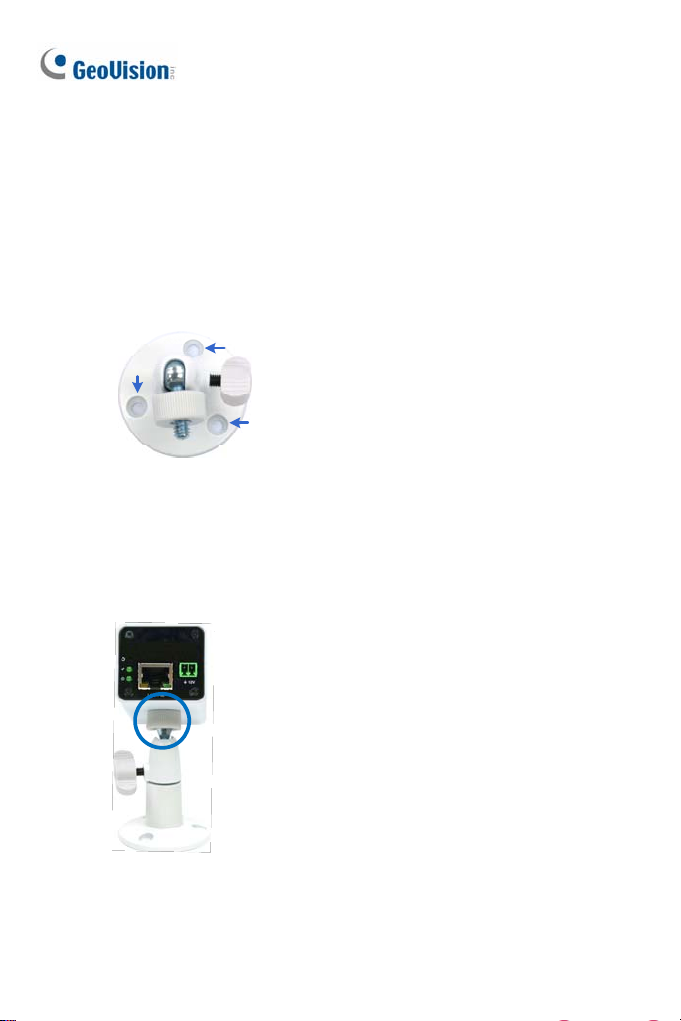
6. Bas
ed on the live view, adjust the angle of the camera. Loosen the
indicated screw with the supplied big torx wrench and adjust the joint.
Tilt Adjustment
Pan Adjustment
28
Page 64

4
IR Arctic Box Camera
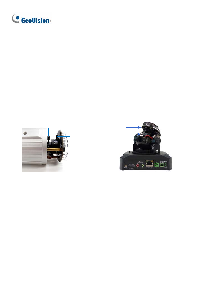
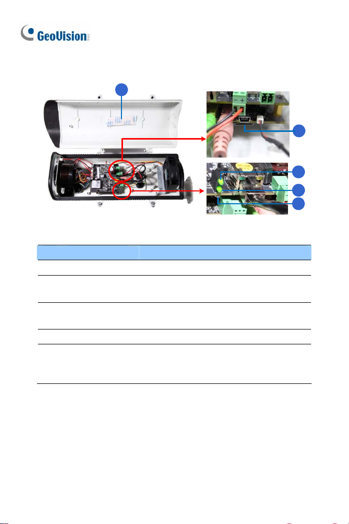
7. For GV-B
3400-E / 5300-E, adjust for image clarity based on the live view.
IMPORTANT: Unscrew and remove the cover carefully. Pulling the cover off
may cause damages to the inner wiring of the camera.
X120D-E / 220D-E / 320D-E / 520D-E / 1500-E / 2400-E /
A. Unscrew the cover with the supplied 4 mm torx wrench.
B. Hold and unplug the connector.
29
Page 65
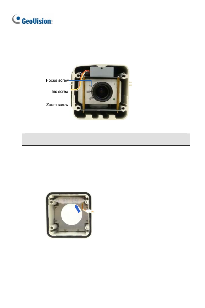
just the focus, zoom and iris screws. For a more precise focus,
C. Ad
use GV-IP Device Utility. For details, see 21.3 Adjusting Image
Clarity in the Quick Start Guide.
Note: Only GV-BX520D-E and GV-BX5300-E contain an iris screw.
D. Replace the silica gel bag. Paste the sticker to the front side of
the silica gel bag. Press the sticker several times to make sure it
adheres properly and paste the silica gel bag to the indicated
place.
E. Follow steps 7B and 7A to plug the connectors back and close
the camera cover.
30
Page 66

4
IR Arctic Box Camera
8. For GV-B
A. Open the camera cover using the supplied torx wrench.
X2510-E / 5310-E, optionally insert a memory card.
B. Insert a memory card to the card slot.
Memory card slot
C. Replace the silica gel bag. Paste the sticker to the silica gel bag.
Press the silica gel bag several times onto the camera cover to
make sure it adheres properly.
D. Follow step 8A to close the camera cover.
31
Page 67

4.4 Connecting the Camera
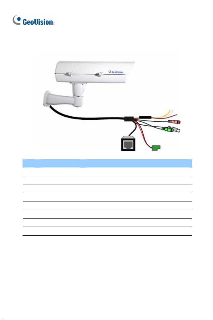
For GV-BX120D-E / 220D-E / 320D-E / 520D-E / 1500-E / 2400-E /
3400-E / 5300-E
No. Wire Definition
1 RJ-45 PoE
2 Black BNC t TV ou
3 Green RCA Audio Out
4 Pink RCA Audio In
ow t ow to connect t
Foll he steps bel he camera:
1. Optionally connect a speaker (green) and a
(pink).
2. Optionally connect a monitor using a Video Out wire. Enable this
function by selecting your signal format at the TV Out field on the
interface. See Video Settings section, Administrator Mode Chapter,
GV-IPCAM H.264 Firmware Manual on the Software DVD.
n external microphone
Web
32
Page 68

4
IR Arctic Box Camera
3. Connect
the camera to a GV-PA481 PoE adapter as illustrated to
supply power and network access.
POWER &
Rear Panel
Power Hub/Router
DA
TA OU
PoE
T
DATA IN
Ethernet Cable
GV-BX-E
4. The status LED of the camera will be on.
5. You are ready to access the live view.
Note: For using the IR Arctic Box Camera, ensure that you:
1. enable the IR LED function on the Web interface after loading the
default settings.
2. disable the status LED to reduce reflection when a green light
spot appears on the live view.
For details, see Notice for Using th e IR Arctic Box Camera section, IR
Arctic Box Camera Chapter, GV-IPCAM H.264 Firmware Manual on the
Software DVD.
33
Page 69
For GV-BX2510-E
/ 5310-E
No. Wire Definition
1. Green RCA Audio Out
2. Pink RCA Audio In
3. Brown wire Digital Output
4. Yellow wire Digital Input
5. White wire GND
6. Terminal Block DC 48V
7. BNC TV Out
8. RJ-45 Ethernet/PoE++
1. Optionally connect the audio out (green), audio in (pink), digital output
(brown), digital input (yellow), and GND.
2. Optionally connect a monitor using a Video Out wire. Enable this
function by selecting your signal format at the TV Out field on the Web
interface. See Video Settings section, Administrator Mode Chapter,
GV-IPCAM H.264 Firmware Manual on the Software DVD.
34
Page 70

4
IR Arctic Box Camera
3. Supply the camera with power and network access using one of the
following methods:
Use a GV-PA482 Power over Ethernet adapter to connect the
camera to power and network as illustrated below. GV-PA482 PoE
adapter is an optional accessory. For detail, see Options in the Quick
Start Guide.
Rear Pane l
DC 48V Power Adaptor
Ethernet Cable
Hub/Router
Power
PoE
Use the supplied power adapter. Connect the black wire of the power
adaptor to the plus (+) port and the white wire to the negative (-) port.
Connect the camera to network with a network cable.
Terminal Block from
the Camera Cable
4. You are ready to access the live view.
DC 12V Power Adaptor
35
Page 71

5. Mini Fixed Dome & Mini Fixed Rugged Dome
5.1 Packing List
GV-MFD
Mini Fixed Dome
Torx Wrench
Self Tapping Screw x 2
Screw Anchor x 2
Cable stopper
2-pin terminal block (for GV-MFD120 / 130 / 320)
Short-Body RJ-45 Plug (for GV-MFD1501 series / 2401 series / 2501
series / 3401 series / 5301 series)
USB / Audio Y-cable (for GV-MFD1501 series / 2401 series / 2501
series / 3401 series / 5301 series)
Power Adapter
GV-IPCAM H.264 Software DVD
GV-NVR Software DVD
Warranty Card
Note: The power adapter can be excluded upon request.
36
Page 72

Mini Fixed & Rugged Dome
5
GV-MDR
Mini Fixed Rugged Dome
Torx Wrench
Self Tapping Screw x 2
Screw Anchor x 2
Cable stopper
Cable Connector
Installation sticker
Silica gel bag x 2
Adhesive Tape x 2
Ferrite core for vehicle installation
GV-IPCAM H.264 Software DVD
GV-NVR Software DVD
Warranty Card
Note:
1. The power adapter can be excluded upon request.
2. When purchasing GV-MDR1500 / 3400 / 5300, choose one of the two
LAN connector types (for motor vehicles or for general use). For
details, see LAN Connector, 5.2 Overview in the Quick Start Guide.
37
Page 73
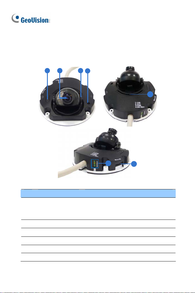
5.2 Overview
GV-MFD120 / 130 / 320
1 2 3
4
5
6
7
No. Name Description
Resets the camera to factory default. See
1 Default Button
2 Lens Receives image inputs.
3 Tilt Screw Loosens the screw to adjust tilt angle.
4 Built-In Microphone Provides one-way audio.
5 Pan Screw Loosens the screw to pan.
6 LED Indicators See LED Indicators below.
38
24. Restoring to Default Settings later in
the Quick Start Guide.
Page 74

Mini Fixed & Rugged Dome
5
No. Name Description
Receives a micro SD card (SD/SDHC,
7 Memory Card Slot
version 2.0 only, Class 10) to store
recording data.
LED Indicator
LED Name Description
1. Link Turns only when the network is connected.
2. ACT Turns on when data are being transmitted.
3. PWR Turns on when power is on.
4. SW RDY (Status) Turns on when the system is ready.
39
Page 75

GV-MFD1501 Series / 2401 Series / 2501 Series / 3401 Series / 5301 Series
2
1
3
4
6
5
7
No. Name Description
1 Microphone Receives sound.
2 Pan Screw Loosens the screw to pan.
3 Lens Receives image inputs.
4 Tilt Screw Loosens the screw to adjust tilt angle.
5 Default Button
6 DC 5V Power Port Connects to power.
7 LAN / PoE Connects to a 10/100 Ethernet or PoE.
8 Memory Card Slot
9 USB and Audio Out
Note: For details on limitations and requirements of the USB port, refer to
Note for USB Storage and WiFi Adapter at the beginning of the Quick
Guide.
Resets the camera to factory default. See
24. Restoring to Factory Default Settings.
Inserts a micro SD card (SD/SDHC,
version 2.0, Class 10) to store recording
data.
Connects to an external hard disk drive and
a speaker through the supplied Y cable.
8
9
40
Page 76

Mini Fixed & Rugged Dome
5
1
2
3
4
LED Name Description
1. Link Turns on (green) when the network is connected.
2. ACT Turns on (orange) when data are being transmitted.
3. Status Turns on (red) when the system is ready.
4. Power Turns on (green) when power is on.
41
Page 77

GV-MDR
1
2
3
4
5
8
10
9
11
No. Name Description
1 Silica gel bag Absorbs the moisture inside the camera.
2 Conceal paper
3 Lens Receives image inputs.
4 Rotation Disc Rotates the camera lens.
5 Pan Disc Pans the camera lens.
6 Tilt Screw Loosens to tilt the camera.
7 Built-In Microphone Provides one-way audio.
8 Default Button
Prevents water or moisture from entering
the camera.
Resets the camera to factory default. See
24. Restoring to Default Settings later in
the Quick Start Guide.
6
7
42
Page 78

Mini Fixed & Rugged Dome
5
No. Name Description
Power and status
9
LED
10 LAN LED Turns on when the network is connected.
11 Memory Card Slot
IMPORTANT: In case of damage and possible condensation inside the
camera housing, be sure not to touch or remove the conceal paper.
Turns red when the power is on. Flashes
orange light twice when the system is
ready.
Receives a micro SD card (SD/SDHC,
version 2.0 only, Class 10) to store
recording data.
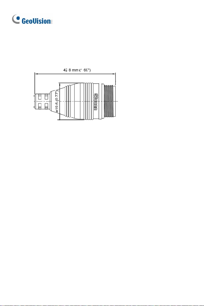
LAN Connector
Two types of LAN connector are available for GV-MDR1500 series / 3400
series / 5300 series. Select an option based on your installation
environment.
1.
Waterproof M12 4-Pin Female Connector
The M12 connector is used for motor vehicles.
Ø14.7 mm (0.58'')
43
Page 79
Small Waterproof Connector
2.
For this connector type, see GV-MDR, 5.3 Installation to install the
supplied cable connector.
44
Page 80

Mini Fixed & Rugged Dome
5
5.3 Installation
To install a Mini Fixed Dome, make sure the installing site is shielded from
rain and moisture.
GV-MFD Series
1. Unscrew the housing cover using the supplied torx wrench.
2. Put the camera on the desired location and make 2 marks on the
ceiling for screw anchors. If you want to run the cables inside the
ceiling, make a round mark with a diameter of 2.5 cm.
3. Drill the marks and insert the screw anchors.
4. Secure the Mini Fixed Dome to the ceiling with the self-tapping screws.
5. Connect the camera to network and power. For details, see 5.4
Connecting the Camera in the Quick Start Guide.
6. Access the live view. See 21.2 Accessing the Live View in the Quick
Start Guide.
7. Adjust the angles based on the live view.
Pan Adjustment
45
Page 81

Tilt Adjustment
8. Insert a memory card (SD/SDHC, version 2.0 only, Class 10) into the
memory card slot.
Memory Card Slot
9. Adjust image clarity using the GV-IP Device Utility program. For details,
see 21.3 Adjusting Image Clarity in the Quick Start Guide.
10. Secure the housing cover using the supplied torx wrench.
11. Optionally conceal the cable opening with the supplied cable stopper.
46
Cable stopper
Page 82

Mini Fixed & Rugged Dome
5
GV-MDR Series
1. Paste the installation sticker on the desired location. The arrow should
point toward the direction that the camera faces.
2. Drill one hole on each of the two curves for screw anchors. Drill the
circle (30 mm in diameter) if you want to run the cable into the ceiling.
30 mm
Drill a hole
on each
3. Insert the screw anchors.
4. Unscrew the housing cover using the supplied torx wrench.
5. Secure the camera body to the ceiling with the self-tapping screws.
47
Page 83
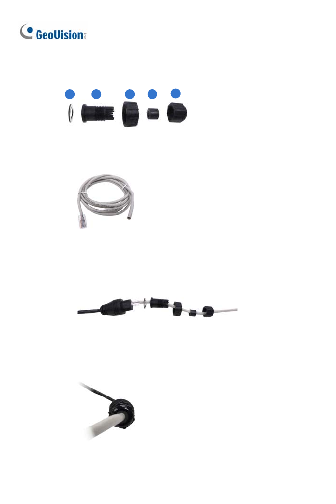
6. Inst
all the cable connector to waterproof the cable. You should have 5
parts:
1 2 3 4
5
A. Prepare an Ethernet cable with the RJ-45 connector on one end
only.
B. Connect the Ethernet cable to the camera cable.
C. Paste the sticker to the camera cable and slide in all the
components as shown below.
D. Move all the components toward the RJ-45 connector, fit item 4 to
item 2, secure item 3 to the camera cable and finally secure item
5 to item 2 tightly.
48
Page 84

Mini Fixed & Rugged Dome
5
IMPORTANT: Item 5 must be secured tightly to waterproof the
cable.
7. Access the live view. See 21.2 Accessing the Live View in the Quick
Start Guide.
8. Adjust the angles based on the live view.
Pan Adjustment
Tilt Adjustment
Rotational Adjustment
49
Page 85
just image clarity using the GV-IP Device Utility program. For details,
9. Ad
see 21.3 Adjusting Image Clarity in the Quick Start Guide.
10. Insert a memory card (SD/SDHC, version 2.0 only, Class 10) into the
memory card slot.
11. Replace the silica gel bag.
IMPORTANT:
1. The silica gel bag loses it effectiveness when the dry camera is
opened. To prevent the lens from fogging up, replace the silica gel
bag every time you open the camera, and conceal the gel bag in
camera within 2 minutes of exposing to open air.
2. For each newly replaced silica gel bag, allow it to absorb moisture
for at least 5 hours before operating the camera.
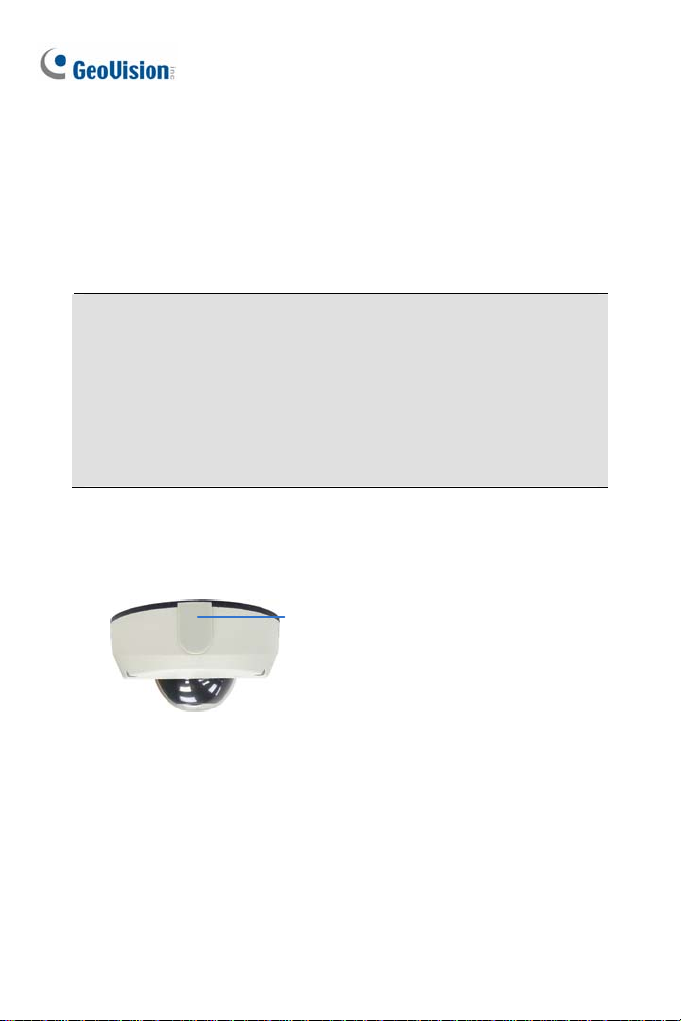
12. Secure the housing cover using the supplied torx wrench.
13. Optionally conceal the cable opening with the supplied cable stopper.
Cable stopper
50
Page 86

Mini Fixed & Rugged Dome
5
5.4 Connecting the Camera
Refer to the wire definition and illustrations below to connect the power and
network.
5.4.1 Wire Definition
GV-MFD120 / 130 / 320
The data cable provides connections for power and network access. The
wires are illustrated and defined below:
No. Wire Color Definition
1 Yellow DC 12V+
2 Orange GND
3 Gray PoE, Ethernet
GV-MDR Series
Power and network connectivity is provided through a PoE cable.
Wire Color Definition
Gray PoE, Ethernet
51
Page 87

5.4.2 Power and Network Connection
Use one of the following methods to power on and connect your camera to
network:
Wired connection with PoE: Use a Power over Ethernet (PoE)
adapter to connect the camera to the network, and the power will be
provided at the same time.
Wired connection with network cable (GV-MFD Series only):
Connect the camera with a standard network cable and use the power
adapter to supply power. See Powering On the Camera below to
assemble the terminal block with power adapter.
Wireless connection (GV-MFD1501 Series / 2401 Series / 2501
Series / 3401 Series / 5301 Series only):
GV-WiFi Adapter (optional accessory) and use the power adapter to
supply power.
Powering On the GV-MFD120 / 130 / 320
1. Insert the orange wire of the camera to the left pin (-) and the yellow
wire to the right pin (+) of the terminal block.
Connect the camera with a
2. Connect the power adapter to the terminal block.
3. Connect the camera to network using a network cable.
52
Terminal Block
DC 12V Power Adaptor
Page 88

Mini Fixed & Rugged Dome
5
5.4.3 Vehicle Installation
To install the Mini Fixed Rugged Dome on a vehicle, clip the ferrite core to
the camera cable. The ferrite core must be attached as close as possible to
the camera with the maximum distance of 15 cm.
Max. 15 cm
Ferrite Core
53
Page 89

6. Target Mini Fixed Dome
6.1 Packing List
Target Mini Fixed Dome
Screw x 2
Screw Anchor x 2
Focus Adjustment Clip or Ring
GV-IPCAM H.264 Software DVD
GV-NVR Software DVD
Warranty Card
Note: The power adapter can be purchased upon request.
54
Page 90

6.2 Overview
1
Target Mini Fi xed Dome
6
a b
3
4
5
2
6
7
No. Name Description
1 Lens Receives image inputs.
2 Pan Screw Loosens the screw to adjust pan angle.
3 Tilt Screw Loosens the screw to adjust tilt angle.
4 Microphone Receives sound.
5 Default Button Resets the camera to factory default. See 24.
Restoring to Factory Default Settings.
6 DC 12V Port Connects to power.
7 LAN / PoE Connects to a 10/100 Ethernet or PoE.
a Status Turns on (green) when the system is ready.
b Power Turns on (green) when power is on.
c Link Turns on (green) when the network is connected.
d ACT Turns on (orange) when data are being
transmitted.
c
d
55
Page 91

6.3 Installation
The Target Mini Fixed Dome can be installed on the wall or the ceiling.
Before installing the camera, make sure the installing site is shielded from
rain and moisture.
1. Open the housing cover by turning.
2. Place the camera where you want to install it and make 2 marks on the
ceiling or the wall for screw anchors. If you want to run the cables
inside the ceiling or the wall, make a round mark with a diameter of 2.5
cm.
3. Drill the marks and insert the screw anchors.
56
Page 92

Target Mini Fi xed Dome
6
4. Thread the power and / or network cable(s) through the oval-shaped
hole or the cable opening on the side, and connect the camera to
network and power. For details, see 6.4 Connecting the Camera.
5. Secure the Target Mini Fixed Dome to the ceiling or the wall with the
self-tapping screws.
6. Access the live view. For details, see 21.2 Accessing the Live View in
the Quick Start Guide.
7. Loosen the tile screw and pan screw, adjust the angles based on the
live view as needed, and tighten the screws again.
Tilt Screw
Pan Screw
8. Adjust image clarity using the GV-IP Device Utility program. For details,
see 21.3 Adjusting Image Clarity in the Quick Start Guide.
9. Place the housing cover back and turn to secure it.
57
Page 93

6.4 Connecting the Camera
1
2
1. Connect power using one of the following methods:
Plug the power adapter to the 12V terminal block. The power
adapter is an optional device. For detail, see Options in the
GV-IPCAM H.264 Hardware Manual for Target Mini Fixed Dome on
the Software DVD.
Use the Power over Ethernet (PoE) function and the power will be
provided over the network cable.
The power and status LEDs shall turn on (green).
2. Use a standard network cable to connect the camera to your network.
3. You are ready to access the live view, adjust the image clarity and
configure the basics. See 21. Accessing the Camera in the Quick Start
Guide.
58
Page 94

Target Mini Fi xed Rugged Dome
7
7. Target Mini Fixed Rugged Dome
7.1 Packing List
Target Mini Fixed Rugged Dome
Screw x 2
Screw Anchor x 2
Focus Adjustment Ring
Installation Sticker
Conduit Converter
RJ-45 Connector
Waterproof Rubber Set (for RJ45 and DC12V)
Torx Wrench
Silica Gel Bag x 2
Adhesive Tape x 2
Concave Hexagon Wrench
Ruler
Screw for Conduit Converter x 2
GV-IPCAM H.264 Software DVD
GV-NVR Software DVD
Warranty Card
59
Page 95

Note:
1. Power adapter can be purchased upon request.
2. You can choose to run the wires through a conduit pipe. After you
have threaded all the wires, install the supplied conduit converter
with a PG21 conduit connector and a self-prepared conduit pipe (of
1/2’’, 3/4’’ or 1’’) to the camera. Do not use a 1/2’’ pipe if you use the
power adapter for power supply because the adapter cannot be
threaded through. A plastic PG21 conduit connector for 1/2” pipe can
be purchased upon request.
Plastic PG21
conduit connector
Conduit pipe
Conduit converter
60
Page 96
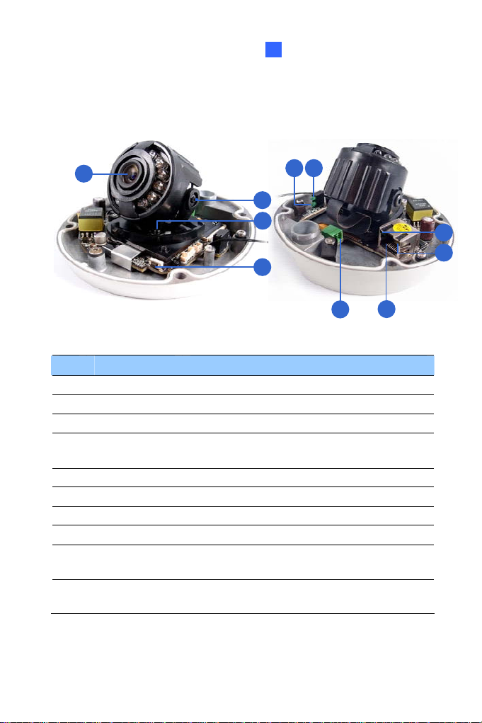
7.2 Overview
Target Mini Fi xed Rugged Dome
7
1
a b
2
3
4
5
6
No. Name Description
1 Lens Receives image inputs.
2 Pan Screw Loosens the screw to adjust pan angle.
3 Tilt Screw Loosens the screw to adjust tilt angle.
4 Default Button
5 DC 12V Port Connects to power.
6 LAN / PoE Connects to a 10/100 Ethernet or PoE.
a Status Turns on (green) when the system is ready.
b Power Turns on (green) when power is on.
c Link
d ACT
Resets the camera to factory default. See 24.
Restoring to Factory Default Settings.
Turns on (green) when the network is
connected.
Turns on (orange) when data are being
transmitted.
c
d
61
Page 97
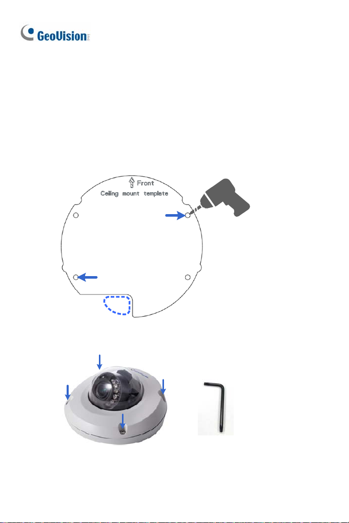
7.3 Installation
The Target Mini Fixed Rugged Dome can be installed on the wall or ceiling.
You must use the supplied waterproof rubber set to waterproof the cable.
1. Paste the installation sticker where you want to install, and drill two
holes that are at a diagonal. To run the cables inside the wall or ceiling,
drill a larger opening as shown below.
2. Insert the supplied screw anchors into the two drilled holes.
3. Open the camera’s housing cover using the supplied torx wrench.
62
Page 98
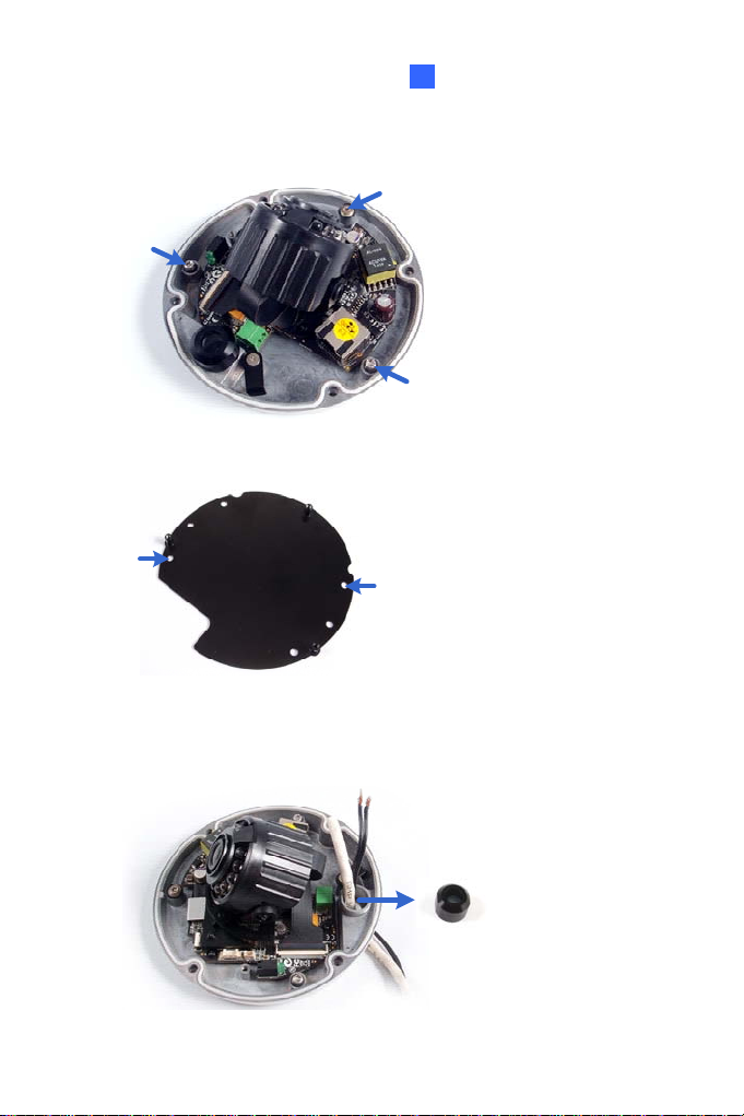
Target Mini Fi xed Rugged Dome
7
4. Unscrew the three screws as indicated below. A back plate can be
separated from the bottom.
5. Use the 2 supplied screws to secure the back plate onto the ceiling or
the wall where the screw anchors were inserted.
6. Prepare an Ethernet cable with the RJ-45 connector on one end only.
7. Remove the waterproof cap from the cable opening and thread the
power and / or network cable(s) through the opening.
63
Page 99
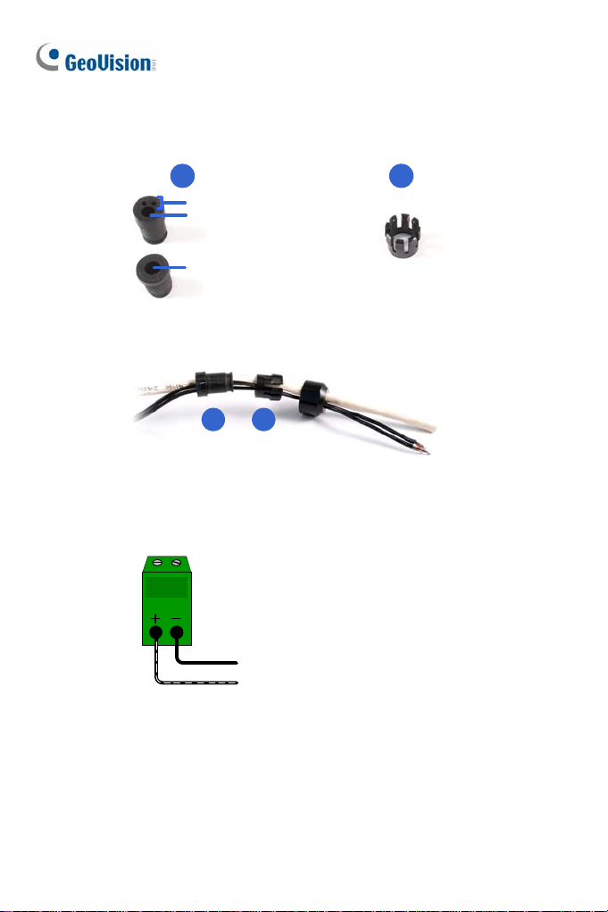
8. Inst
all the supplied waterproof rubber set onto the cable(s). The rubber
set has two parts. Item 1 comes in two types.
21
For power cable
For network cable
For network cable (PoE)
A. Slide the waterproof rubber set, and the waterproof cap you
previously removed through the cable(s) as shown below.
21
B. Connect the supplied RJ-45 connector to the Ethernet cable.
C. If you are using a power adapter, insert the striped wire to the left
pin (+) and the other wire to the right pin (-).
64
Page 100

Target Mini Fi xed Rugged Dome
7
D. Fit item 1 to item 2, and insert them in the cable opening. Use the
supplied ruler to make sure the length of the cable(s) from the
bottom of the opening to the end of the cable is under 10 cm.
E. Cap the cable opening with the waterproof cap. Use the supplied
concave hexagon wrench to tighten.
65
 Loading...